

Page 1

®
WWW.ALLOMATIC.NET
SW-350DC & SW-300DC Installation Manual
Copyright © 2008 all-o-matic inc. www.allomatic.net
®
L
D
I
E
S
T
Pending
UL325
compliant
UL991
compliant
US
Page 2

TABLE OF CONTENTS
Important safety instructions ....
Different UL 325 class types.............................................................
Concrete pad Specs for SW-300DC.................................................
Concrete pad Specs for SW-350DC.................................................
Concrete Operator & Arm Layout..............................................
Compact Installation........................................................................
Torque limiter & Arm adjustment......................................................
Gate travel adjustment.....................................................................
Directional settings..........................................................................
Electrical power connections...........................................................
Typical loop layout...........................................................................
General loop installation guidelines.................................................
Accessory connections....................................................................
Multiple safety device connections..................................................
Plugin detector installation..............................................................
....................................................
2&3
7,8&9
4
5
6
10
11
12
13
14
15
16
17
18
19
Leading edge installation................................................................
Three button station........................................................................
Magnetic/Solenoid lock installation.................................................
Master/Slave connections...............................................................
Radio receiver hookup....................................................................
Open & Close electronic reversing sensor(ERD) adjustment.........
Timer adjustment............................................................................
Dip switch functions........................................................................
Emergency release for SW-350DC................................................
Solar panel installation...................................................................
Led Diagnostics.............................................................................
Swinger arm parts..........................................................................
20
21
22
23
24
25
26
27
28
29
30
31
1
Page 3

IMPORTANT SAFETY INSTRUCTIONS
WARNING
To reduce the risk of
READ THE FOLLOWING DIRECTIONS. DO NOT EVEN THINK OF STARTING UNTIL
YOU HAVE READ AND UNDERSTAND THESE DIRECTIONS. IF THERE IS
SOMETHING YOU DO NOT UNDERSTAND CALL US.
Never
children.
Always keep people and objects away from the gate. No one should cross the path of
the moving gate.
This operator must be tested monthly. The gate must reverse on contact with a ridged
object or stop when an object activates the non-contact sensors. After adjusting the
force or the limit travel, retest the gate operator. Failure to adjust and retest the gate
operator properly can increase the risk of injury.
Use the emergency release only when the gate is not moving.
let children operate or play with gate controls. Keep the remote control away from
injury:
Keep gates properly maintained. Have a qualified service person make repairs to gate
hardware. It takes many years of experience to make proper adjustments to gate
hardware or operators.
This entrance is for vehicles only. Pedestrian must use separate entrance.
There is nothing on a gate operator that is easily repaired without a great deal of
experience. Save yourself some time and call a qualified Gate Service Contractor who
knows your type of gate operator.
SAVE THESE INSTRUCTIONS
2
Page 4

INSTALL THE GATE OPERATOR ONLY WHEN
YOU HAVE READ THE FOLLOWING:
*Confirm that the gate operator being installed is appropriate for the application.
*Confirm that the gate is designed and built according to current published industry standards.
*Confirm that all appropriate safety features and safety accessory devices are being incorporated, including
both primary and secondary entrapment protection devices.
*Make sure that the gate works freely before installing the operator.
*Repair or service worn or damaged gate hardware before installation of the operator.
*Eliminate all gaps in a sliding gate below a 4 foot height that permits a 2 ¼ inch sphere to pass through
any location, including the area of the adjacent fence covered when the gate is in the open position.
*Eliminate all gaps in a swinging gate below a 4 foot height that permit a 4 inch sphere to pass through any
location, including the hinge area of the gate.
*Operator must be disconnected from the power source before attempting any installation of accessories.
*Install this gate operator according to our installation instructions.
*Adjust the operator clutch or load sensing device to the minimum force setting that will still allow for reliable
gate operation.
*Install the operator inside the fence line(do not install the operator on the public side of fence line).
*Install a proper electrical ground to a gate operator.
*Controls intended for user activation must be located at least six feet (6’) away from any moving part of the
gate and where the user is prevented from reaching over, under, around or through the gate to operate the
controls. Outdoor or easily accessible controls shall have a security feature to prevent unauthorized use.
The Stop and/or Reset button must be located in the line-of-sight of the gate. Activation of the reset control
shall not cause the operator to start.
*Install a minimum of two(2) WARNING SIGNS, one on each side of the gate where easily visible and take
pictures of the installation.
*Test all safety features for proper function before placing the automatic vehicular gate into service.
*Train owner/users about basic functions and safety features of the gate system, including how to turn off
the power and how to operate the manual disconnect feature.
*Leave safety instructions, product literature, installation manual and maintenance manual with end user.
*Explain to the owner/user the importance of routine service and retesting on a monthly basis.
3
Page 5

DIFFERENT UL 325 CLASS TYPES
Class one: Residential
A vehicle gate operator intended for use at a home of one to four single family dwellings,
garages or parking area.
Class Two: Commercial or General Public Access
A vehicular gate operator intended for use at a commercial location or building such as a
multi-family housing unit (five or more single family units), hotel, garages, retail stores,
other buildings servicing the general public.
Class three: Industrial or limited Access
A vehicular gate operator intended for use at an industrial location or building such as a
factory, loading dock area, or other locations not intended to service the general public.
Class Four: Restricted Access
A vehicular gate operator intended for use at a guarded industrial location or building
such as airport security areas or other restricted access locations not servicing the
general public where unauthorized access is prevented via supervision by security
personnel.
Other components required to satisfy UL 325
Each class must have a primary and secondary means to sense and react to
obstructions within two seconds.
The six types of obstruction sensing systems are:
Type A:
Inherent obstruction sensing system. This system must sense and initiate the reverse of
the gate within two seconds of contact with a solid object.
Type B 1:
Provision for connection of a non-contact device can be used, such as a secondary
protection.
Type B2:
Provision for connection of a contact sensor. Examples include an edge device or
equivalent. This can be used for secondary protection.
Type C:
Inherent adjustable clutch or pressure relief valve.
Type D:
Provision for connection of or provided with and actuation device requiring continuous
pressure.
4
Page 6
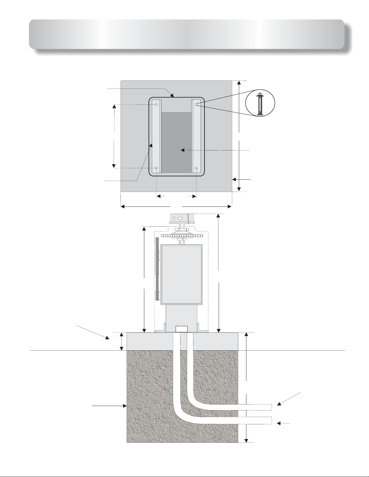
CONCRETE PAD FOR SW-300DC
Operator plastic
Cover
Four red head
Bolts
1
/2
”
X 3
1
/2
”
Operator frame
When possible
13.5”
23”
9.5”
24”
24”
Area for Conduit(s)
Operator Concrete
Pad
25.5”
Install 4” above
Ground
Footing for
Gate operator
4”
Low voltage
Single Conduit for
24”
Master/Slave
High voltage
conduit
5
Page 7
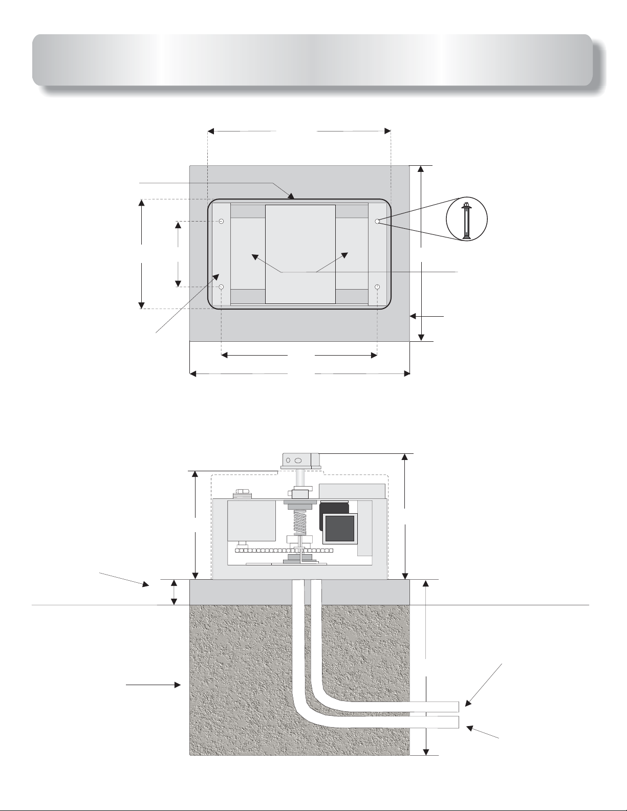
CONCRETE PAD FOR SW-350DC
1
/2
25 ”
Operator plastic
cover
15”
Operator frame
9”
21
30”
Four red head
X 3
”
1
/2
”
24”
Bolts
1
/2
Area for Conduit(s)
Operator concrete pad
1
/2
”
When possible
install 4” above
ground
Footing for
gate operator
4”
14
1
17 / ”
1
/2
”
4
Low voltage single
conduit for Master/Slave
24”
High voltage
conduit
6
Page 8
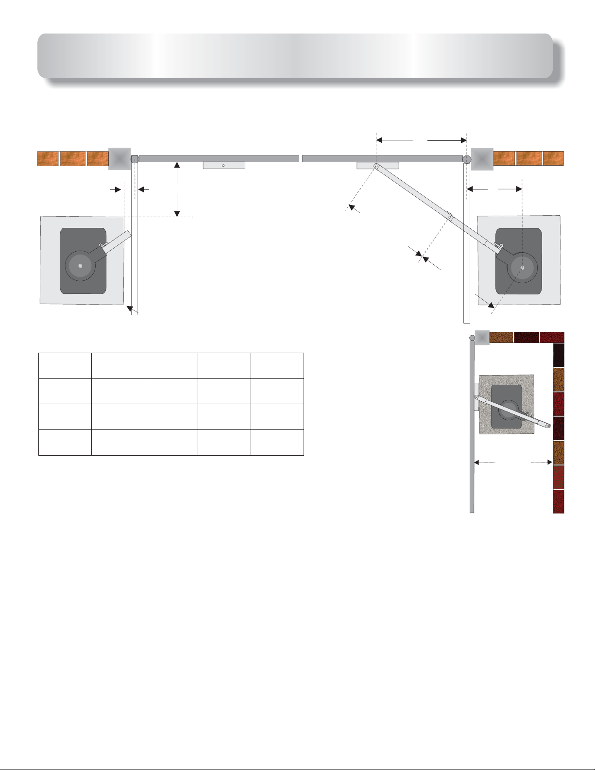
OPERATOR AND ARM DIMENTIONS
HINGE
CENTER
POST
OUTSIDE
A
This distance is from
the gate in open
position to edge of the
pad. Refer to .note
Dimentions Chart
Gate
length
Less than
12”
13’-15’
16’-22’’
B
35”
41”
47”
B
C
14”
14”
2”
CONCRETE PAD
A
36”
42” 14”
48”
INSIDE
Minimum
Distance
34”
37”
40”
SECONDARY
PRIMARY
C
Minimum
distance
Refer to
note
below.
: Is the distance between the gate bracket and the gate
A
hinge point.
B
: Is the distance between the gate hinge point and the edge
of the concrete pad.
C
: Is the distance from the gate in the open position to the center
shaft of the operator.
Minimum distance
: Is the minimum distance required behind
the open gate. If the distance between the
open gate and the back wall is between 20”
and 33” refer to compact installation.
Note: The 2” distance shown above is from the gate in the open position to the edge of the pad.
If the gate must open more than 90 degrees, the pad needs to move back accordingly. The
distance between the open gate and the pad needs to remain 2”. The distance “C” also needs to
move back accordingly if the opening is more than 90 degrees.
7
Page 9

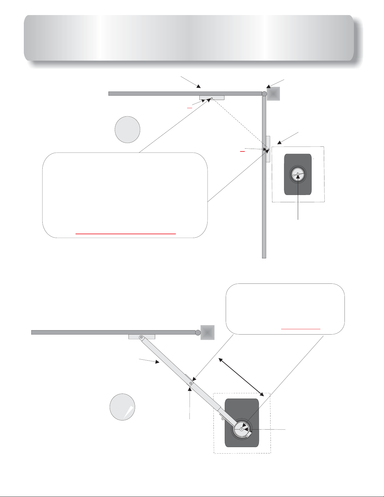
OPERATOR AND ARM LAYOUT
Out
In
Mark ground under
gate bracket with
gate closed. This will
be point Y
1
Point Y
Mark ground under
gate bracket with
gate open. This will
X
be point Z
“A”
Bracket
Point Z
Hinge point
Bracket
X
14”
Bracket
Out
In
Draw a line from point
past the point as shown.
This should be laid on the
ground. The operators
center shaft goes on this
line.
Point Y
Y
Z
2
Hinge point
X
Bracket
Point Z
X
Center shaft of
Operator
8
Page 10
ARM LAYOUT & OPERATOR
PLACEMENT CONTINUED
Bracket
Point Y
3
Measure distance from the Y
And point Say distance is 60”,
Z.
divide this number by 2,which =30”.
This is the length of primary arm in
next drawing.
PLEASE BE EXACT!!!
point
X
Point Z
Hinge point
Bracket
X
Center shaft of
Operator
This pipe does not need to
be measured after primary
arm is installed this pipe
makes up the balance of
arm.
4
+
CENTER OF
BOLT AT FIRST
HINGE POINT
This ARM section is half the
distance between point
and point as shown above.
IT MUST BE EXACT!!!
PRIMARY ARM SECTION
+
Z
CENTER OF
SHAFT ON
OPERATOR
Y
9
Page 11

SWINGER COMPACT
INSTALLATON
To use this installation the gate must be 12’ or less.
HINGE
CENTER
27”
OUTSIDE
INSIDE
8”
SECONDARY
Use these measurements, only if the
distance between the wall and the gate
in the open position is 20” to 34”. If you
have more than 34” refer to standard
installation.
35”
20”
20” Minimum
10
Page 12

TORQUE LIMITER AND ARM
The torque limiter is shipped loose (not adjusted). You must
use a 20” pipe wrench to adjust the large torque limiter nut on the
operator as shown in the images below.
Tighten torque limiter nut until arm does not slip when the
operator is running.
Also run gate and grab gate at mid cycle to make sure torque
limiter will slip. This is an important adjustment, so please take your
time and do it right.
20” Pipe wrench
Torque limiter
adjusting nut.
Top view
MASTER
Torque limiter
adjusting nut.
SW-350DC
ARM ADJUSTMENT:
bolt to hold the arm lever in closed
position. With the arm lever closed tighten
the arm adjusting screw as tight as
possible.
ARM QUICK RELEASE:
arm with the quick release, simply remove
the bolt or padlock from the arm lever and
open it. Opening the arm lever will allow
you to manually open the gate.
1
9
9
1
1
0001000
1
1
1
1001
0R
0R9
0
0R
90
9
1
100
B
1
1
B
B
0
00
10R010
90R990R9
1
B
1
10R0
6
9
0001000
0
1
16
2
SSSS
6
6
R0
8
829B
R
R
1414
IORIOR
0
0618
6
1
8
I
IR
R
2
2110S
1
1
0
S
10
1
1
10
1
1
0
0
0
00
0
02
0
0
0
2
2
2
2
2
100110
10
1
10
1
00
00
0
0
0
1
1
1
1
1
------
--
--
--
--
-
-
-
-
-
-
-
-
-
-
-
-
-
-
-
-
-
-
-
-
-
-
-
-
N
--OPEN----------
E
-
P
---
O
-
-
-
-
-
-
-
-
-
-
-
-
-
-
-
-
------------
-
-
-
-
-
-
---
-
-
-
8
7
6
5
4
3
2
1
1 2 3 4 5 6 7 8
1
1001
0
0
1
M
I
A
2AIM
2
8
8
1
100
0
0
1
1
4
4
6
C
MC6
M
L
L
B
B
R
R
8
C
C8
1
12
2
1
10
0
1
1
7
710
1
0
0
0
0
0
2
2
K
KE.
E
.
7
71
1
0
0
K
KE.
E
.
M
MAGNECRAFT
W107DIP- 3W107DIP- 3
A
GN
E
CRA
FT
9
M1AM
A
1
1
1
001
0
0
1
00
0
0
2
2
2
2
5
58
8
AD
A
L
Ls07
D
s
M
MOC
C1K
C
1
1
9
90R9
1
10
0
00
1
1
1
10
0
0
9
90R9
1
1
1
1
B
B
B
00
0
001
1
10
90R990R9
1
10
1
1
0
0
0R0
SSSS
0
00
R
0
0
141
4
IOR
0
0618
6
1
8
I
I
R
R2110S
2
1
1
0
S
-
-
-
-
-
-
-
-
-
-
-
-
-
-
-
-
-
-
-
-
-
-
-
-
N
E
P
O
-
-
-
-
-
-
-
-
-
-
-
-
-
-
-
-
-
-
-
-
-
-
-
-----------------------OPEN------------------------
8
7
6
5
4
3
2
1
1 2 3 4 5 6 7 8
1
100
0
0
1
1
M
IM
I
A
2
8
82A
1
1001
0
0
1
4
64
6
C
C
M
L
LM
B
R
8
C
C8RB
1
1
2
210
1
0
1
1002
710710
0
0
2
K
K
E.
E
.
7107
10
K
KE.
E
.
M
MAGNECRAFT
W
A
1
G
0
7
NE
D
IP
C
RA
3W107DIP- 3
F
T
9
M
M
A
1
1A
1
10
0
01
0
1
0
002
0
2
2
2
5
58AD
8
A
L
Ls07
D
s
M
MOC8050
C1K
C
0
7
O
1
K
C
6
629Q
G
G
8
2
4
4
0
9
5
Q
F
0
0
1
KE.
KE.
710710
7
710
1
1
002
0
1
10
0
0
02
0
2
2
1
15
1
15
5
5
0
01
0
0
1
1
1
3
2
1
6
B
B
6
0
9
9
R9
R
R
0
0
0
00
0
6
0
0
0
1
9
16
1
2
0
01
2
1
SSS
S
SSSS
0
0
00
1
6
616
2
6
R9
R
R0
0
0
8
829
8
829B
1
6
8
829
1
1
0
R
R
R
R6
0
R
R616
141
4
1414
IOR
IOR
0
0
6
618
1
8
0
0
6
618
1
8
I
I
R
R
2
211
1
1
0
0S
S
I
I
R
R
2
211
1
1
0
0S
S
1
1001
0
0
1
1
1
1
1
1002
1
0
0
0
00
0
0
02
0
0
AT
ATME
M
L
E
L
2
2
2
2
A
A
T
TM
M
E
G
E
A168
G
A
1
6
8
2
20AU 0743
0
A
U
0
7
4
3
KE.KE.
7
72CB74K
2
5145
710710
C
1
10
1
1
B
B
1
10
4
L
Ls14
6
9
0
16
1
0
0
0
1
2
B
6
8
829
s
0
0
0
01
0
01
R
R6
1
1
1
1
1
7
4
4
K
7
72CB74K
2
C
B
7
4
K
G
G4
4
G
G
1
1
4
4
3
33
L
Ls14
s
1
4
3
2
2
2
2
0
0
0
0
01
5
50
1
7
4
47
M
I
A
2
8
82AIM
1
0
4
64
6
C
MC
M
L
L
0
001
2
2
C
CMX-309FB C
B
B
8R
8R
C
C
1
1AM
A
M
M
9
X
-3
8
8.0000 M
.0
0
5
535202
9
3
0
F
5
0
B
2
0
C
0
M
2
4
475
7
5
0
0
1
1001
0
0
1
1
1001
0
0
1
1
O
U
B
R
N
S
3
3
6
8
3
1
1
001
0
0
1
1
1
001
0
0
1
P
PHIL
H
IL
IP
IP
1
S
S
P
PHILIPS
O
U
B
R
N
H
S
3
3
6
IL
8
3
IP
1
100
0
1
100
0
0
1
1
0
1
1
S
1
O
U
B
R
N
S
3
3
6
8
3
5
58ADC1K
7
72CB74K
7
72CB74K
8
2
2
A
C
C
L
L
L
L
D
L
Ls14
s
s07
B
B
s
s14
s
C
0
1
7
1
7
7
1
4
4
4
4
K
K
K
G
G4
G
G4
G
G4
4
4
4
0710
1
KE.
KE.KE.
KE.
KE.
KE.
KE.
710710
710710
710710
710710
7
710710
1
100
0
1
1002
0
0
1
1
2
002
2
0
0
1
1
0
2
002
0
1
10
2
0
0
1
10
02
2
0
0
2
02
0
2
1
15
1
1501
1
1
1
1
1
1501
1
15
5
5
5
5
5
5
5
5
0
01
0
0
01
0
01
0
0
0
1
1
1
1
1
1
1
.01.01
I0
I0615
5W5W
6
1
I
5
O
/
O
2
2001
0
0
1
C
Coilcraft
o
1
104
ilc
0
F
4
r
a
6
602
0
2
F
F260
ft
S
S26
2
6
S
2
S
6
6
602
S
S26
0
0
2
2
6
6
6
0
02
2
S
S
2
2
6
6
S
N
ONO
G
2
0
B
0
6
8
802
3
360G
L
L
8
8
C
C8R
M
MC
2
6
62
2
2
22
2
2AI
8
A
C
R
I
64
6
M
M
B
B
4
2
2491
4
9
1
1
100
H
HFK.
7
7J2
476E
0
J
W
C
2
F
Z
4
7
U
U 74ZF2CW
F
3
R
0
0R3
0
9
90
2
0
DW
W
D
06
6
9
0
9
3
C3
C
U
U
K
.
1
C
0
9
911C0
1
476E
A
7
0
1
107A
3
R
0
0
9
900R3
9
9531
1
1
4
4750
1
1
1
1
5
7
2
212
3
31
3
5
1
1
1
0
2
2
2491
4
9
1
L
L
8
8
C
C8
M
M
2
2AI
8
A
C
C
R
R
I
6
6
M
M
4
40
0
21
2
1
B
B
4
4
3
360G
8
802
6
0
B
0
2
G
ONON
C
Coilcraft
o
6
683
ilc
8
V
3
r
a
f
t
2
20M
0
M
KE.
710710
L
L
8
8
C
C8RB
M
MC
2
2A
8
A
C
R
I
I
6
64
3
360G
6
M
M
0
G
B
4
B
2
2402
4
0
2
1
10
0
02
0
2
8
802
0
2
1
100
0
0
1
1
ONON
1
F
0
B
0
001
A
1
1
1
A
2
1
1001
0
0
1
1
1
5
5
S
S21B
M
MAAF
0
01
1
5GN5GN
HFKHFK
33
1
1
0
0
0
02
2
1
1
0
0
5
5
1
1
V
V
U
DR
DR127-330
4
43CL07 E
3CL0
12
7-330
7 E
Side view
0
7
O
1
K
C
6
6
G4
G4
8050
8
2
2
0
9Q
9
5
Q
F
0
.
.
.
.
0
0
0
0
0
0
E
E
E.
E
1
1
1
1
K
KE
K
K
K
KE.
7
71
7
71
7
7
10
1
0
10
1
0
0
0
1
1002
2
0
0
2
0
2
2
0
2
1
15
1501
1
1
5
5
50
01
0
01
1
1
6
6
00
9
9
9
R
000
0
0
0
01
16
1
1
29B
2
2
2
SSSS
SSSS
0
01
1
6
6
616
6
R
R
R
0
0
9
8
8
8
8
1
1
0
R
R
R
R
0
9
9
1414
1414
IORIOR
I
IOR
O
R
0
06
6
1
1
8
8
0
0618
6
1
8
I
IR
R
2
21
1
1
1
0
0S
S
I
IR2110
R
2
1
1
0
S
S
1
1001
00
1
AT
ATMEL
M
E
L
AT
ATMEGA168
M
E
G
A
1
6
8
2
20
0
AU
A
0743
U
0
7
4
3
.
.
E
E
K
K
7
72CB74
2
5
0
1
7
710
C
B
4
L
Ls
6
9B
9
1
1451
2
B
6
616
8
82
s
R
R
14
1
7
4
4
K
K
7
72
2
C
CB
B
7
4
K
74K
G
G4
4
G
G
1
4
4
3
L
Ls1
s
1
4
4
32133
2
2
2
0
0
0
0
0
01
5
1
7
75
4
4
M
I
A
2
8
82AIM
1
1
0
0
4
6
C
M
L
LMC64
0
0
2
2
C
CMX-3
B
B
R
R
8
C
C8
1AM1
A
M
M
9
X
8
8
3
.0
.0000 M
0
09FB C
5
535202
9
3
0
F
5
0
B
2
0
C
0
M
2
4
4
7
75
50
0
2
2001
0
0
1
1
1
001
0
0
1
1
1001
0
0
1
1
O
U
B
R
N
S
3
3
6
8
3
1
1
001
0
0
1
1
1001
0
0
1
PHI
P
H
I
LIP
LIP
1
S
S
PHILIPS
O
U
B
R
N
S
3
3
6
8
3
1
1001
0
0
10
1
0
1
0
0
1
1
1
O
U
B
R
N
S
3
3
6
8
3
5
58
7
7
7
72
8
2
2
2
A
A
CB74
C
CB
C
L
L
L
Ls1
DC1K
D
L
Ls
s
s
B
B
s
s
C
0
0
1
7
14
1
7
7
7
7
1
4
4
4
4
4
4
K
K
K
K
K
G
G
G
G4
G
G
4
4
4
4
4
.
.
.
.
.
.
.
.
.
.
0
0
0
0
0
0
0
0
0
E
E.
E
E
E
E
E
E
E
1
1
1
1
1
1
1
1
1
K
K
K
KE.
K
K
K
KE
K
K
K
KE
7
7
7
7
7
710
7
710
7
710
7
7
1
1
002
0
1
1
0
00
0
1
1002
2
02
0
10
1
10
1
2
002
0
02
0
0
0
1
1
2
2
2
00
0
02
2
1
1
15
1
1
1
1
150115
15
15
501150
5
50
501
5
5
0
0
0
0
01
0
01
1
1
1
1
1
1
1
.01.01
I
I0615
0
5W5W
6
1
I
5
O
/
O
C
C
o
oilcraft
1
104
il
0
c
F
4
r
a
6
602
0
2
F
F2
ft
S
S
2
2
6
6
S
2
S
6
6
6
602
S
S26
0
0
0
2
2
6
6
602
0
2
S
S26
2
6
S
ONON
B
802802
360G360G
L
L
8
82AIM
C
C
M
MC64
2
2
6
6
2
2
22
2
8
8RB
A
C
R
I
6
M
B
4
2
249
4
91
1
1
100
H
HFK.
7
7J2
E
6
7
4
476E
0
J
W
C
2
F
Z
4
7
U
U 74ZF2CW
F
3
R
0
0
9
900R3
2
0
DW
W
D
06
6
9
0
9
3
C3
C
U
U
K
.
C
0
1
1
9
911C0
E
6
7
4
476E
A
7
0
1
107A
3
R
0
0
9
900R3
9
95
11
1131
4
47
1
1
5
7
2
212
3
3
31
5
5
1
1
1
0
0
2
2
4
91249
1
L
LM
8
82A
C
C8R
M
2
8
A
C
C
R
I
I
6
6
M
M
4
4021
0
2
1
B
B
4
4
3
360
8
802
6
0
B
0
2
G
G
ONO
N
C
Coilcraft
o
6
683
il
8
V
c
3
r
a
ft
2
20M
0
M
L
LMC6
8
82AI
C
C
M
2
8
8RB
A
C
R
I
6
3
360G
6
M
M
0
G
B
4
4
B
2
2
402
4
0
2
8
802
0
2
1
1001
0
0
1
ONON
1
1
F
0
0
0
AF
10
1
AA
A
1
10
0
0
0
1
1
S21BS21B
M
M
N
K
F
G
5
5GN
H
HFK
3333
1
10
0
02
0
2
1
1
0
0
5
5
1
1
V
V
U
D
DR127-330
4
43CL07 E
R
3
C
1
2
L
7
0
-
7
3
3
E
0
SW-300DC
Use a pad lock or a
To release the
Arm adjusting
screw
Allen wrench
11
Page 13

GATE TRAVEL ADJUSTMENT
Locate limit switch.
Step 1: Turn the on operator.
Step 2: Use an allen wrench to loosen up the limit cams. Turn the
limit Cams to desired direction.
Step 3: tighten the allen screw.
Step 4: Turn the operator back on.
Step 5: Run gate operator. If more adjustment is needed, repeat
the steps.
power off
Limit switches
Limit cams
Allen wrench
12
Page 14

OPENING DIRECTION SETTINGS
Use dipswitch to change the opening direction on the
operator. for , forleft hand opening right hand opening.
OPEN L/R
LED’s will show opening or
closing directions when gate
is running.
ONOFF
O
.01
/
O
I
5W
I0615
F260
U
6
2
02
02
S
6
6
S
6
0
2
S
S
2
1
0
0
2
1
0
0
1
U
O
0
1
5
0
7
0
1
4
1
-----------------------OPEN------------------------
C
N
S
3
R
3
8
6
B
3
1 2 3 4 5 6 7 8
oilcra
104
F
1
0
0
1
1
0
0
1
P
PHILIPS
H
IL
I
1
0
0
1
ft
N
S
R
U
O
B
1
P
S
PHILIPSPHILIPS
L
8
C
M
2
8
A
C
R
I
6
M
B
4
1
0
0
0
21
1
1
6
3
3
8
6
1
0
0
1
6
1
6
R
B
9
2
8
14
SS
9
0
R
9
1
0R
0
100
0
1
0
0
1
6
1
6
R
B
9
2
8
14
SS
9
0
R
9
1
0
R
0
100
1
0
0
2
0
1
0
0
1
6
1
6
R
B
9
2
8
14
SS
9
0
R
9
1
0
R
0
1
000
7
K
1
0
0
1
10
E
.
0
6
I
R
1
8
IORIOR
0
6
1
8
IORIOR
0
6
1
8
IORIOR
4
G
2
1
1
0
74K
S
I
R
2
1
1
0
S
IR
2
1
1
0
S
s14
L
72CB
6
1
6
R
B
9
2
8
5
4
1
2
0
0
1
1
3
3
2
9
1
A
M
0
5
7
4
1
0
0
2
8
3
L
6
4
1
E
7
A
0
M
G
U
AT
ATMEL
E
A
0
M
2
AT
L
8
C
M
2
8
A
C
R
IM
6
B
4
CMX-309FB C
72CB74K
G
4
Ls14
8.0000 M
535202
1
0
0
2
1
0
0
1
1
0
0
2
1
0
0
1
1
0
0
2
1
0
0
1
11
6
C
U
2
3
S
7
9
S
9
4
0
Z
6
F
D
2
W
4
C
W
36
0G
B
1
911C0
8
02
0
O
N
100
7
A
HFK.
7J2
C
8
R
B
L
M
C
64
8
2A
IM
2
4
9
1
2
E
E
3
6
3
6
6
2
R
2
7
0R
7
4
4
900
90
1
0
N
S
0
3
1
R
3
U
8
O
6
B
1
0
0
1
3
1
3
MAGNECRAFT
1
M
A
1
0
9
0
W107DIP- 3
1
1
0
0
2
.
.
0
E
E
K
K
71
710
1
0
0
1
2
0
4
20M
2
C
8R
B
L
M
C
64
8
2A
IM
1
2
1
2
3
1
5
3
1
3
8
7
5
0
6
0
B
0G
2
O
N
1
2
0
4
2
4
9
1
6
8
3
C
o
ilcr
af
t
V
C
8
RB
L
M
C
6
4
8
2A
IM
O
N
802
B
360G
KE.
2
0
710
0
1
72C
B74K
G
4
Ls14
KE.
2
0
710
0
1
KE.
2
0
710
0
1
58ADC1K
G
4
Ls07
KE.
2
0
710
0
1
KE.
2
0
710
0
1
KE.
72C
B74K
G
4
2
0
710
0
Ls14
1
KE.
2
0
710
0
1
KE.
2
0
710
0
1
58AD
C1K
G
4
Ls07
KE.
2
0
710
0
1
F
2
2
MOC8050
0
0
629Q
6
0
4
0
1
2
1
2
1
0
0
1
3
0
0
2
5GN
HFK
33
B
21
S
F
A
A
M
1
0
0
1
DR127-330
43CL07 E
15
01
15
01
150
1
1
5
01
1
50
1
1
5
01
1
501
15
01
1
501
RS
1
2
3
Opening to the left
-----------------------OPEN-----------------------------------------------OPEN------------------------
1 2 3 4 5 6 7 81 2 3 4 5 6 7 8
LMC64LMC64
82AIM
C8RB
1002
KE.
1001
1001
710
1210
Opening to the right
13
Page 15

ELECTRICAL CONNECTION
OPERATORS BE PROPERLY GROUNDED!MUST
GRD
115V
LINE 1
LINE 2
Power switch
120 Volt
Electrical
Plug.
Power connection | 115VAC | 220VAC Single Phase
LINE 1
LINE 2
Connect to . Use a proper for a
ground reference.
Use the shortest and thickest wire possible for ground.
230V
NOTE: When applying 230V to
operator make sure voltage
switch is flipped to 230V
position.
= 115V N 220V LINE 1
= 115V HOT 220V LINE 2
groundGND
ground rod
For power, a minimum of a
15-Amp
dedicated circuit
breaker is needed.
NOTE: To use the 120VAC
accessory outlet, connect white
wire from the outlet to neutral.
Only when using 120VAC as the
power source.
For power wire enclosure
use UL listed conduits.
All gate operators be properly grounded.
A proper ground in a gate operator installation minimizes or prevents damage from an electrical charge, such as a near
lightning strike or an electrical static discharge.
.
Use a single wire for the ground. splice two wires for the ground. If the wire breaks or is cut, replace it with a
single length. use two wires for the ground.
Check with your City code for proper earth ground rod type and proper grounding procedures.
MUST
DO NOT
NEVER
14
Page 16

WIRED IN SERIES
SWINGER LOOP LAYOUT
Outside Safety loop
5 FT
5 FT
Gate in open
Gate in open
position
position
TWISTED 6
TURNS
PER FOOT
5 FT
Center Phantom loop
5 FT
Inside Safety loop
5 FT
Exit loop
WHEN USED
5 FT
1/4 IN1/4 IN
1 1/2 IN
This is a normal loop layout. Remember when connecting to an All-OMatic circuit board you use the your
safety loop detector and from the exit loop.
normally open contacts
normally closed contacts
from
You must twist your wires from your exit point of the saw cut all the way
to the circuit board, no exceptions.
15
Page 17

GENERAL LOOP INSTALLATION GUIDELINES
The following loop installation guidelines are for installing typical driveway loops for access
control applications (i.e. parking gates, sliding gates, swing gates etc...) Always consult with
loop detector manufacturers for specific equipment guidelines. This will confirm that the
proper configuration and installation techniques are applied for your application.
Useful information about inductive loops:
A. The typical sensing height is 2/3 of the shortest leg of loop (in feet)
Therefore a 4’ x 8’ loop typically has a detection height of 2.6’.
B. The inductance of a conventional four-slide loop can be estimated
using the formula:
L = P x (T + T) / 4 Where L = Loop Inductance in microHenries
2
Therefore a 4’ x 8’ loop with 3 turns would be:
L=(4 + 8 + 4 + 8) x (3 + 3) / 4
L=24 x (9 + 3) / 4
L=24 x 12 / 4
L=24 x 3
L=72 microHenries
Suggested guidelines for loop
installation:
Loop wires should be twisted 6 turns
per foot, and twisted from saw slot to
the detector. If possible start twisting
the wires from the edge of the loop.
All 90 degree corners should be
chamfered so that the course of the
wire does not change direction
sharply but rather at shallower angles
of 45 degrees or less. Core drilling of
the corners achieves the same effect
but can still lead to failure due to
sharp edges remaining in the corner
area.
2
Loop
Perimeter
6’ - 12’ 6
13’ - 20’ 5
21’ - 60’ 4
61’ - 240’’ 3
241 & Up 2
P = Loop Perimeter in feet
T = Number of turns of wire in saw slot
TWISTED 6
TURNS
PER FOOT
1/4’’ Feeder Slot
Driveway loop
45
Angles
Driveway
Sealant: 3/4’’ to 1’’ Min.
Backer Rod
# of
Turns
Saw Slot
2’’
1/4’’
Loop Wire: 3 Turns
}
16
Page 18

ACCESSORY CONNECTIONS
The circuit board output provides up to mAmps of power for
12 or 24VDC 500
accessories. More than two or three accessories will require a separate power
supply.
12 or 24VDCNOTE:
1002
1002
1501
See page 14 for plugin loop
detector installation.
EXIT
Loop
Detector
Power
Detect
SENS.
LEVEL
BOOSTON
PULSEPULSE
FREQ.
Loop Fail
Reset
1 2 3 4 5 6
0
2
0
1
OFF
PRESPRES
0
2
0
1
Accessories only.
1002
1002
1002
1501
1501
1501
1002
1002
1002
1501
1501
1501
1501
C
360G
1002
1002
1002
1501
1501
1002
1501
1501
U
V
V
B
802
O
N
1
Remove wire jumper
from when
SAFETY
a safety device is
C
Power
Detect
SENS.
LEVEL
BOOSTON
PULSE
FREQ.
Loop Fail
Reset
1 2 3 4 5 6
0
2
1
0
SAFETY Loop
OFF
PRES
0
2
0
1
Detector
installed.
N/C
50
1
501
1
LMC64
82AIM
C8RB
1001
1
0
02
1
0
0
2
DR127-330
43CL07 E
MAAF
2402
1001
604
1001
S21B
0
3002
1212
5GN
HFK
33
Keypad
or
Telephone
Push Button
or
Fire Box
Card Reader
or
Key Switch
A
B
C
D
E
F
1
2
3
G
H
I
J
K
L
M
N
O
4
5
6
P
Q
R
S
T
U
V
W
X
Y
Z
7
8
9
TO
N
E
O
P
E
R
*
0
#
AB
PHOTO Beam
See page 18 for connection of
N/O
multiple safety device wiring
diagram.
= COMMON
C
N/O
= NORMALLY OPEN CONTACT
N/C
= NORMALLY CLOSED CONTACT
17
Page 19

MULTIPLE SAFETY DEVICES
CONNECTIONS
Multiple devices installed together must be connected .
in seriesSAFETY “ ”
Locate the white loop rack safety wire and connect with common wire of
second device. Dry contact (N.C.) from second device goes to on
the circuit board B
jumper from the position
. efore installing the accessory devices, remove the wire
SAFETY
on the control board.
SAFETY
Safety wire connections
From Loop rack to Second Accessory
White safety wire To Relay COM
1002
1002
1002
1002
1501
1002
1501
1501
1501
1002
1002
1002
1002
1501
1501
1501
1501
1002
1501
1501
From Second Accessory To Board pin
Relay N.C. To SAFETY
360G
1002
1002
1501
1501
U
V
V
B
802
O
N
1
1
150
150
43CL07 E
LMC64
82AIM
C8RB
1001
1
0
0
2
1
0
0
2
DR127-330
MAAF
2402
1001
1001
S21B
3002
121
2
5GN
HFK
33
6040
Loop Rack
Loop
Safety
Loop
Phantom
Loop
onnections
Exit
Loop C
Safety Loop
Phantom Loop
Exit Loop
See side for
Jumper setting
Safety
Phantom
Exit
Ground
12VDC
24VAC/
WHITE
safety wire
Relay
(N.C.)
AB
PHOTO
Beam
Remove jumper
from when
a safety device is
wire
SAFETY
installed.
Relay (COM)
Wire nut
This diagram is for the relay wires of the safety devices, two wires to the board connections (one from
each device) and two wires to the orange wire nut.
18
Page 20

®
LPR-1 LOOP RACK INATALLATION
This is a loop configuration for a gated driveway. Remember when connecting to an
All-O-Matic circuit board the safety (reverse) uses from the loop
typical
normally closed contacts
detector, the wire jumper from the safety connector needs to be removed when a safety loop
is inatalled.
You must twist your wires from your exit point of the saw cut all the way to the loop
detectors, no exceptions.
Exit loop
WHEN USED
Exit Loop
Inside Safety loop
Loop Connections
24VAC/
12VDC
Ground
Exit
Phantom
Safety
Jumper setting
Phantom Loop
See side for
Safety Loop
Exit
Loop
Phantom
Loop
Safety
Loop
Center Phantom loop
NOTE:
To wire one or multiple safety devices in use
with loop rack safety device remove loop rack
safety white contact wire (N.C.) From safety
pin connector on circuit board and wire in
Series with added safety devices using the
(N.C.) Contact wire from your safety device in
the safety contact. (see page 13)
43CL07 E
DR127-330
1501
1002
33
HFK
5GN
1501
002
1212
6040
1001
1
3002
MAAF
S21B
1001
1001
2402
B
R
8
C
N
O
802
B
4
360G
6
IM
C
A
2
M
8
L
V
Compatible Detectors
Brand Model No.
Reno A&E
EDI
Diablo Controls
U
V
H2
LMA-1500-LP
DSP-40S
Outside Safety loop
1501
1501
1501
1501
1501
1501
1501
1501
1002
1002
1002
1002
1501
1002
1002
1002
1002
1501
1501
1002
1002
1501
1002
1002
Jumper setting
OFF
OFF
ON
19
Page 21

LEADING EDGE CONNECTION
LMC64
82AIM
C8RB
360G
1002
1002
1002
1002
1501
1002
1501
1501
1501
1002
1002
1002
1002
1002
1002
1501
1501
1501
1501
1501
1501
1002
1501
1501
U
V
V
wire to 12VDCRED
wire to COMMONBLACK
B
802
O
N
1501
1501
43CL07 E
1001
1002
1002
DR127-330
MAAF
2402
1001
6040
1001
S21B
300
121
2
2
5GN
HFK
33
LEADING EDGE SENSOR
Wireless
edge
Receiver
A wireless contact sensor such as one that transmits radio frequency (RF) signals to the gate
operator for entrapment protection functions shall be located where the transmission of the
signals are not obstructed or impeded by building structures, natural landscaping or similar
obstruction. A wireless contact sensor shall function under the intended end-use conditions.
Connect one of the wires from leading edge and/or one of the grey
wires from a wireless edge receiver to connector
COMMON
on
control board.
Connect the other wire from leading edge and/or the other wire from
a wireless edge receiver to connector control .
EDGE
on board
20
Page 22

THREE BUTTON STATION
See push button connections below.
A three button station was integrated
on the board to make adjustments
easier when setting limit switches
and adjusting ERDs.
SYSTEM
LMC64
C8RB
1210
1
710
0
0
2
KE.
710
KE.
MAGNECRAFT
W107DIP - 3
9
1AM
1
0
0
1
0
0
2
2
58ADC1K
Ls07
MOC8050
629Q
G4
F
KE.
KE.
710
710
1
0
0
2
1
0
0
2
1501
1501
1
O
U
B
R
N
S
3
3
6
8
3
1
0
0
1
1
0
0
P
PHILIPS
H
ILIP
S
PHILIPS
72CB74K
Ls14
G4
KE.
KE.
710
710
1
0
0
2
1
0
0
2
1501
1501
58ADC1K
Ls07
G4
KE.
KE.
710
710
1
0
0
2
1
0
0
2
1501
1501
1
1
O
U
B
R
N
S
3
3
6
8
3
1
0
0
1
1
0
0
1
1
O
U
B
R
N
S
3
3
6
8
3
72CB74K
Ls14
G4
KE.
KE.
710
1
0
0
2
1501
KE.
710
710
1
0
0
1
2
0
0
2
1501
1501
360G
F
476E
90
476E
90
802
B
Coilcraft
104
2262
2491
3
0R
3
0R
O
N
N
O
B
802
360G
LMC64
82AIM
C8RB
HFK.
100
7J2
0
911C
07A
1
2491
LMC64
82AIM
C8RB
4
0
2
1
Coilcraft
683
V
Connect the from all the push buttons
to input on the board.
COMMON
Connect push button contact to
EXIT
input on the board.
Connect push button contact to
3BT
input on the board.
Connect push button Contact to
PED-SW
PED-SW
COMMON
OPEN N.O.
CLOSE N.O.
STOP N.C.
input on the board and remove
jumper.
N.O.
N.O.
N.C.
OPEN
CLOSE
STOP
V
V
U
PED-SW
Jumper
COM
21
Page 23

MAGNETIC/SOLENOID LOCK
CONNECTIONS
Magnetic lock installation requires a step down transformer with appropriate voltage for the
specific lock accessory. Operator will provide a 120VAC outlet for the step down transformer.
Connections:
For Magnetic lock:
the other wire from transformer will be connected to the relay plug input and the relay
Plug the lock device transformer to the 120VAC outlet plug.
Connect one wire from transformer directly to one wire of the magnetic lock,
COM MAG
output connects to the other wire of the magnetic lock. See illustration below.
For Solenoid lock:
connect the other wire from transformer to the relay plug input and the relay output
Connect one wire from transformer directly to one wire of the solenoid lock,
COM SOL
connects to the other wire of the solenoid lock. See illustration below.
SS
90R9
1
0
R
0
1
0
0
0
1001
6
1
6
R
B
9
2
8
14
SS
0618
90R9
1
0
R
0
1
0
0
0
IR
21
10S
IOR
8
3
L
6
4
1
E
7
A
M
0
G
U
AT
ATMEL
E
A
0
M
2
AT
72CB74K
1002
1002
1002
2001
L
8
C
M
2
8
A
C
R
IM
6
B
4
CMX-309FB C
G
4
Ls14
1001
1001
1001
IORIOR
14
8.0000 M
535202
1
4750
1001
-----------------------OPEN------------------------
3
1 2 3 4 5 6 7 8
1001
1
P
PHILIPS
H
IL
IP
S
PHILIPS
L
8
C
M
2
8
A
C
R
IM
64
B
1001
3
1
3
58ADC1K
G
4
Ls07
72CB74K
G
4
Ls14
58ADC1K
G
4
Ls07
MAGNECRAFT
W107DIP - 3
1002
9
F
M
A
1
MOC8050
0022
1001
629Q
1
5
0
1
KE.
710
1002
1
5
0
1
KE.
710
1002
1
5
0
1
KE.
710
1002
1
5
0
1
KE.
710
1002
1
5
0
1
KE.
710
1002
1
5
0
1
KE.
710
1002
1
5
0
1
KE.
710
1002
SOLENOID
LOCK
MAGNETIC
LOCK
1001
1001
Relay plug
.
.
0
E
E
10
K
K
7
71
1210
120VAC
outlet plug
Step Down
Transformer
22
Page 24

MASTER/SLAVE CONNECTION
Before connecting master/slave gate operators together, test and adjust limit switches and the
ERDs for each operator as “ ” machines.
stand alone
the
All accessories must be installed on the master board, no exception.
See page 27 for dip switch settings.
Use a two wire and run it through a UL listed conduit for master/slave connection.
shielded cable
Follow the wiring diagram as shown below.
Master Board Slave Board
+.....................Positive to Positive...................+
-...................Negative to Negative...................-
Use UL listed
conduit
Shielded
cable
Slave Board
Master Board
-----------------------OPEN------------------------
1 2 3 4 5 6 7 8
1210
1001
1001
710
KE.
710710
KE.
82AIM
LMC64
C8RB
1002
Slave switch
only on
ON
slave board
-----------------------OPEN------------------------
1 2 3 4 5 6 7 8
1210
1001
1001
710
KE.
710
KE.
82AIM
LMC64
C8RB
1
002
Connect shield to
slave metal frame
only.
23
Page 25

RADIO RECEIVER CONNECTIONS
4 wire receiver: connect the two relay wires to & terminals. Black
wire to terminal and Red wire to terminal on
13negative positive
12
receiver strip outside control box as shown below.
9
1AM
1001
0022
MOC8050
629Q
1
1
0
0
0
R
0
0
F
KE.
710
1002
1501
-----------------------OPEN------------------------
8
7
6
5
4
3
2
1
1
0
0
1
82AIM
1
0
0
1
4
C6
LM
B
8R
C
1
2
1
0
1
71
0
0
0
2
KE
.
7
1
0
K
E
.
M
W107DIP- 3
A
G
N
EC
R
A
F
T
9
M
1A
1
0
0
1
0
0
2
2
M
O
C
629Q
8050
F
.
0
E
1
K
7
1
0
0
2
1
5
0
1
1
9
1
0
1
0
0
0
9
B
0
R
R
6
0
9
0
0
1
2
S
S
1
6
R
8
R
9
4
1
IORIOR
0618
IR2110S
1
1
1
0
0
0
0
0
0
2
2
2
1
1
1
0
0
0
0
0
0
1
1
1
5
3
52
0
2
0
72CB74K
Ls14
G
4
C
M
X
-3
8
.0
09
0
F
00
B
C
M
PHILIPS
S
S
9
1
4
AT
ATMEL
ME
L
ATM
EG
A
168
20
AU
074
3
IM
82A
1
0
4
C6
LM
0
2
8RB
C
4
7
5
0
1
0
0
1
1
3
1
0
0
1
P
PHILIPS
H
IL
I
1
P
S
3
1
0
0
1
1
3
58ADC1K
Ls07
G
4
.
.
0
0
E
E
1
1
K
K
7
7
1
0
1
0
0
2
0
2
1
1
5
5
0
0
1
1
58ADC1
72CB74K
Ls07
Ls14
K
G
G
4
4
.
.
.
.
0
0
0
0
E
E
E
E
1
1
1
1
K
K
K
K
7
7
7
7
1
0
1
0
0
2
1
0
0
2
1
0
0
2
0
2
1
1
1
1
5
5
5
5
0
0
0
0
1
1
1
1
1
1
B
6
9
1
2
6
8
R
IORIOR
0618
IR2110S
1
0
O
U
B
R
3
3
6
8
1
0
O
U
B
R
3
3
6
8
1
0
O
U
B
R
3
3
6
8
0
1
7
1
0
0
2
1
0
0
0
0
0
R
1
0
0
5
B
4
6
9
1
1
2
6
8
R
1
3
3
2
2
0
0
0
5
1
7
4
1
A
M
9
2
0
0
1
0
1
N
S
0
1
N
S
0
1
N
S
72CB74K
Ls14
36
G
0
4
G
.
.
0
E
E
1
K
K
7
1
0
0
2
1
1
5
5
0
0
1
1
1
9
B
0
6
9
0
0
1
2
S
S
1
6
R
8
R
9
1
4
IORIOR
0618
IR2110S
1
0
0
1
.
KE
0
71
72C
B74K
G
4
Ls14
Coilcraft
104
F
N
O
802
L
8
C
M
2
6
2
2
2
8
A
C
R
IM
6
B
4
2
4
9
1
10
H
7J
476E
F
3
R
0
0
9
2
0
K
.
0
C
476E
3
R
0
0
9
2
4
91
L
8
C
M
2
8
A
C
R
IM
6
4
0
2
1
B
4
802
B
O
N
C
o
6
ilcr
83
V
a
ft
V
U
602
F
S26
S
2
S
6
602
S26
0
602
S26
S
B
360G
U 74ZF2CW
1
1
9
107A
UC3906DW
9
11
4
1
5
7
2
3
3
5
1
1
1
0
2
20M
L
8
C
M
2
8
A
C
R
I
6
360
M
G
B
4
B
2
4
0
2
802
O
N
1
0
B
0
AF
1
1
2
S
MA
5GN
HFK
33
1
0
0
2
1501
V
43CL07 E
DR127-330
.01
I0615
5W
I
O
/
O
1
0
0
1
1
0
0
1
Receiver terminal strip
located outside control
box.
3
2
1
3 = 12V
2 = Relay
1 = Common
Pcb also provides
12VDC & 24VDC
Inputs.
4 wire 12VDC
Radio Receiver
24
Page 26

OPEN AND CLOSE ELECTRONIC
REVERSING SENSOR(ERDs)
ADJUSTMENT
O
O
/
I
.01
5W
I0615
F260
6
6
2
2
2
2
0
0
S
S
6
6
S
S
6
0
2
S
2
6
1
0
0
1
6
R61
829B
14
SS
90R9
1
0
R
0
10
0
0
1
0
0
1
16
R6
B
829
14
SS
90R9
1
0
R
0
1
0
0
0
1
0
0
1
16
R6
829B
14
SS
90R9
1
0
R
0
1
00
0
710
KE.
1
0
0
1
0618
IR2110S
IOR
0618
IR2110S
IOR
0618
IR2110S
IOR
4
G
74K
B
Ls14
72C
6
1
6
R
B
9
2
8
5
4
1
2
0
0
1
1
3
3
2
9
1AM
0
5
7
4
1
0
0
2
8
3
L
6
4
1
E
7
A
0
M
G
U
AT
ATMEL
E
A
0
M
2
AT
L
8
C
M
2
8
A
C
R
I
6
M
B
4
CMX-309FB C
72C
B7
4K
G
4
Ls14
8.0000 M
535202
1
0
0
1
1
0
0
2
1
0
0
1
2
0
0
1
1
0
0
2
1
0
0
1
-----------------------OPEN------------------------
1 2 3 4 5 6 7 8
S
104
Coilcraft
F
1
0
0
2
1
1
N
S
N
S
0
0
3
0
3
0
R
R
1
1
3
3
U
U
8
8
O
O
6
6
B
B
1
0
1
0
5
0
0
7
0
1
3
1
1
3
4
1
P
PHILIPS
H
IL
IP
S
PHILIPS
L
8
C
M
1
0
0
2
2
8
A
C
R
I
6
M
B
4
1
1
0
0
0
1
0
0
2
KE.
KE.
1
1
710
710
1
1
2
1
2
UC3906DW
11
3
1
U 74ZF2CW
9
5
3
1
4
7
5
0
360G
B
1
911C0
0
802
100
O
N
7
A
HFK.
2491
7J2
C
8
R
B
C
6
4
A
IM
2491
R
U
O
B
1
MAGNECRAFT
W
C
L
M
8
2
A
E
3
3
R
R
0
0
0
0
476E
476
9
9
7
2C
B7
Ls14
N
S
3
3
8
6
3
5
8A
D
C
Ls07
72CB
Ls14
58A
DC
Ls07
2
1
2
1AM
0
M
9
0
0
1
07D
0
IP
- 3
1
L
M
8
2
2262
1
0
0
1
1
0
0
1
6
0
4
0
1
0
0
1
1
2
1
2
1
0
0
1
3
0
0
2
5GN
2
0
HFK
4
20M
2
33
S21B
MAAF
1
0
0
1
C
8
R
B
L
M
C
6
4
8
2
A
IM
DR127-330
43CL07 E
360G
802
B
O
N
1
2
0
4
683
Coilcraft
V
8
R
B
C
6
4
IM
ON
802
B
360G
1
50
1
.
E
K
2
0
0
71
0
1
4K
G
4
15
0
1
.
E
K
2
0
710
0
1
15
0
1
.
E
K
2
0
0
10
7
1
1K
G
4
1
5
0
1
.
E
K
2
0
0
71
0
1
1
5
0
1
.
E
K
2
0
710
0
1
1
5
0
1
.
E
K
74K
G
4
2
0
710
0
1
1
5
0
1
.
E
K
2
0
0
71
0
1
15
0
1
.
E
K
2
0
710
0
1
1K
G
4
1
5
01
.
E
K
2
0
10
7
0
1
F
O
C
80
50
6
29Q
Open and Close ERD
SENSITIVITY
MAX MAXMIN MIN
N
1001
1001
S
3
R
U
O
B
1
1001
3
8
6
1001
3
N
S
3
R
3
U
8
O
6
B
1
3
ERD’S must be adjusted
by qualified technician.
The gate operator ERDs must be
adjusted so that the gate provides
regular, reliable and safe cycles.
ERD must be checked every six
months.
Counter clockwise maximum
sensitivity
Clockwise minimum sensitivity
When gate stops and reverses by itself,
the ERD is .
The gate must
too sensitive
stop and reverse when it
hits an obstruction or the ERD is
not sensitive enough.
25
Page 27

TIMER ADJUSTMENT
TIMER ON: Timer to close, can be set from 1 to 60 seconds.
TIMER OFF: Gate operation is push button to open, push button to close.
TO TIMER:
OVERRIDE THE Turn the RADIO switch to the “ON” position.
This will allow the radio receiver to close the gate before the timer.
TIMER ADJUSTMENT
Turn potentiometer counter clockwise for more
60
Sec
0
Sec
time.
60
Sec
TIMER “ ” to activate
ON
0
Sec
1001
1
4750
1001
the timer
RADIO “ ” =ON Allows
the transmitter to close
the gate before the timer.
Turn potentiometer clockwise for less time.
N
S
3
R
3
U
8
O
6
B
3
TIMER
RADIO
OSC
FAIL SF/SC
1-PASS
SLAVE
AUTO OPEN
OPEN L/R
OFF ON
1001
1001
-----------------------OPEN------------------------
1 2 3 4 5 6 7 8
O
O
/
I
.01
5W
I0615
F260
6
2
2
0
S
S26
6
602
S
S
60
2
S
2
6
1
0
0
2
1
0
0
1
0
1
5
0
7
0
1
4
1
1 2 3 4 5 6 7 8
L
8
C
M
2
8
A
C
R
I
6
M
B
4
1
1
0
0
0
0
1
1
S
104
Coilcraft
F
1
N
S
N
S
0
3
0
3
R
R
1
3
3
U
U
8
8
O
O
6
6
B
B
1
0
0
3
1
1
3
P
PHILIPS
H
I
L
I
P
S
PHILIPS
1
0
0
2
.
.
0
0
0
E
E
1
1
1
2
K
K
7
7
1
1
0
0
1
6
1
6
R
B
9
2
8
14
SS
90R9
1
0
R
0
1
0
0
0
1
0
0
1
6
1
6
R
B
9
2
8
14
SS
90R9
1
0
R
0
1
0
0
0
1
0
0
1
6
1
6
R
B
9
2
8
14
SS
90R9
1
0
R
0
1
0
0
0
7
K
1
0
0
1
1
E
0
.
0
6
IR
1
2
8
1
1
IOR
0
S
0
6
IR
1
2
8
1
1
IOR
0
S
0
6
IR
1
2
8
1
1
IOR
0
S
4
G
Ls14
72CB74K
6
1
6
R
B
9
2
8
5
4
1
2
0
0
1
1
3
3
2
9
1AM
0
5
7
4
1
0
0
2
8
3
L
6
4
1
E
7
A
0
M
G
U
AT
ATMEL
E
A
0
M
2
AT
L
8
C
M
2
8
A
C
R
I
6
M
B
4
CMX-309FB C
72CB74K
G
4
Ls14
8.0000 M
535202
1
0
0
1
1
0
0
2
1
0
0
1
2
0
0
1
1
0
0
2
1
0
0
1
-----------------------O
PE
N
------------------------
1
2
1
2
UC3906DW
11
3
1
U
74Z
9
5
3
1
F2CW
4
7
5
0
360G
B
1
911C0
0
802
100
O
N
7
A
HFK.
2491
7J2
C8RB
LMC64
82AIM
2491
E
E
3
3
62
6
6
R
R
22
0
0
7
7
0
0
4
4
9
9
1
0
0
1
1
0
0
1
72CB74K
N
S
3
R
3
U
8
O
6
B
1
3
58ADC1K
72CB74K
58ADC1K
M
AG
NECRAFT
2
1
2
M
A
1
0
9
0
0
W
1
0
7
0
D
IP
- 3
1
6
0
4
0
1
0
0
1
1
2
1
2
1
0
0
1
3
0
0
2
M
5
G
N
0
2
0
H
4
F
K
2
2
3
3
B
1
2
S
F
A
A
M
1
0
0
1
C8RB
LMC64
82AIM
DR127-330
43CL07 E
360G
802
B
O
N
1
2
0
4
683
Coilcraft
V
C8RB
LMC64
82AIM
ON
802
B
360G
1
5
0
1
KE.
2
0
710
0
1
G
4
Ls14
1
5
0
1
KE.
2
0
710
0
1
1
5
0
1
KE.
2
0
0
710
1
G
4
1
5
0
Ls07
Ls14
Ls07
MOC8050
1
KE.
2
0
710
0
1
1
5
0
1
KE.
2
0
710
0
1
1
5
0
1
KE.
G
4
2
0
710
0
1
1
5
0
1
KE.
2
0
710
0
1
1
5
0
1
KE.
2
0
710
0
1
G
4
1
5
0
1
KE.
2
0
710
0
1
F
629Q
26
Page 28

DIP SWITCH FUNCTIONS
TIMER
TIMER
OFF ON
-----------------------OPEN------------------------
TIMER ON
1 2 3 4 5 6 7 8
for details
.
switch “ ” activates the TIMER. See page 21
RADIO
RADIO
OSC
FAIL SF/SC
RADIO ON
the timer. See page 21 for details.
switch “ ” allows the radio receiver to override
1-PASS
SLAVE
OSC ON
AUTO OPEN
OPEN L/R
This is to set the operator as fail-safe or fail secure. for on power failure,
board will monitor battery voltage to make sure gate opens before battery drains out
completely. for on power failure gate will run until battery is low and
stay close.
OFF Fail-secure:
reverse the gate n any direction.
signal stops gate, second signal gate.
switch “ ” allows the radio receiver to top and
i During a cycle the first
a reverses
FAIL SF/SC
ON Fail-safe:
OSC
s
1-PASS
This is a true one pass anti-tailgating feature. This feature may only be used with safety
loops. With this switch in the “ ” position, the gate will open until one car passes the
safety loops then it will stop and close. If a second car pulls on the loop the gate will stop
the car must then back off the loop before the gate will close.
,
ON
SLAVE
This feature is used on master/slave setups. Set slave switch “ ” on slave machine, all
other switches “ ”. Set slave switch to the “OFF” position on master machine. Set
other function switches on master machine as desired. See page for more details on
master/slave connections and settings.
OFF
ON
17
AUTO OPEN
This feature is to open the gate on power interruption. It is a very particular
feature used in areas where the fire department requires the gate to open automatically
after a power outage. Set this dip switch “ON” when this feature is desire.
automatic
OPEN L/R
This feature is to set the direction the operator will open. See page 8 for details.
27
Page 29

EMERGENCY RELEASE
For SW-350DC
Procedures to release gate:
1. Turn power OFF.
2. Push pedal down & move pedal
to hold pedal down in position
s
lightly to the right
.
3. Push gate open.
See page 11 for emergency release of SW-300 Operator.
EXIT
T
T
T
A
E
A
E
A
E
G
O
G
O
G
O
P
P
C
P
C
C
I
I
I
E
E
E
T
T
T
R
R
R
A
A
A
A
A
A
T
M
T
M
T
M
O
O
O
O
O
O
T
R
T
T
R
R
S
S
S
U
U
U
A
A
A
®
S
S
S
S
S
S
L
L
L
D
D
D
I
I
I
D
D
D
A
A
A
E
E
E
E
E
E
R
R
R
H
H
H
S
S
S
R
R
R
E
E
E
•
•
•
V
V
V
S
S
S
O
O
O
W
W
W
•
•
•
I
I
I
N
N
N
S
S
S
G
G
G
R
R
R
E
E
E
115VAC
SAFETY
28
Page 30

SOLAR PANEL CONNECTION
The solar panel input will take a 12VDC panel or two 12VDC panels wired in sires to
make 24VDC . The charging circuit is limited by 1 Amp max.
NOTE:
For information on what solar panel to use on any other type of installation
call ALL O MATIC for Assistance.
360G
B
802
N
O
20M
C8RB
LMC64
82AIM
1212
1001
1001
3002
6040
S21B
MAAF
1001
2402
DR127-330
43CL07 E
O
O
/
I
.01
5W
I0615
F260
6
6
2
2
2
2
0
0
S
S
6
6
S
S
6
0
2
S
2
6
1
0
0
1
6
1
6
R
B
9
2
8
14
SS
90R9
1
0
R
0
1
0
0
0
1
0
0
1
6
1
6
R
B
9
2
8
14
SS
90R9
1
0
R
0
1
0
0
0
1
0
0
1
6
1
6
R
B
9
2
8
14
SS
90R9
1
0
R
0
1
0
0
0
7
K
1
0
0
1
1
E
0
.
0
6
IR
1
2
8
1
1
IOR
0
S
0
6
IR
1
2
8
1
1
IOR
0
S
0
6
IR
1
2
8
1
1
IOR
0
S
4
G
Ls14
72CB74K
6
1
6
R
B
9
2
8
5
4
1
2
0
0
1
1
3
3
2
9
1AM
0
5
7
4
1
0
0
2
8
3
L
6
4
1
E
7
A
0
M
G
U
AT
ATMEL
E
A
0
M
2
AT
L
8
C
M
2
8
A
C
R
IM
6
B
4
CMX-309FB C
72CB74K
G
4
Ls14
8.0000 M
535202
1
0
0
1
1
0
0
2
1
0
0
1
2
0
0
1
1
0
0
2
1
0
0
1
-----------------------O
1 2 3 4 5 6 7 8
P
E
N
------------------------
S
104
Coilcraft
F
1
0
0
2
1
1
N
S
N
S
0
0
3
0
3
0
R
R
1
1
3
3
U
U
8
8
O
O
6
6
B
B
1
0
1
0
5
0
0
7
0
1
3
1
1
3
4
1
P
PHILIPS
H
I
L
I
P
S
PHILIPS
L
8
C
M
1
0
0
2
2
8
A
C
R
IM
6
B
4
.
.
1
1
0
0
0
E
E
0
0
1
1
1
0
0
2
K
K
1
1
7
7
1
1
2
1
2
UC3906DW
11
3
1
U 74ZF2CW
9
5
3
1
4
7
5
0
360G
B
1
911C0
0
802
100
O
N
7
1
2
A
0
4
HFK.
2491
7J2
C8RB
LM
1
0
0
1
1
0
0
1
C8RB
C64
LMC64
82AIM
82AIM
2491
E
E
3
3
6
6
R
R
2262
N
R
U
O
B
1
MAGN
W
ON
0
0
7
7
0
802
0
4
4
9
9
B
360G
72CB74K
G
4
Ls14
S
3
3
8
6
3
58ADC1K
G
4
Ls07
72CB74K
G
4
Ls14
58ADC1K
G
4
Ls07
F
ECRAFT
2
1
2
M
A
1
0
MOC8050
9
0
0
1
0
7
0
D
IP
- 3
1
629Q
360G
B
802
N
O
20M
C8R
B
LMC6
4
DR127-330
82AIM
1
2
1
2
1
0
3
0
0
2
6
0
4
0
683
Coilcraft
V
KE.
710
KE.
710
KE.
710
KE.
710
KE.
710
KE.
710
KE.
710
KE.
710
KE.
710
43CL07 E
0
1
1
0
0
1
B
1
2
S
1
0
0
F
A
A
M
1
2
0
4
2
1
5
0
1
2
0
0
1
1
5
0
1
2
0
0
1
1
5
0
1
2
0
0
1
1
5
0
1
2
0
0
1
1
5
0
1
2
0
0
1
1
5
0
1
2
0
0
1
1
5
0
1
2
0
0
1
1
5
0
1
2
0
0
1
1
5
0
1
2
0
0
1
29
Page 31

LED DIAGNOSTICS
AC/PWR ON:
M/S LINK:
ALARM:
1st state: LED will blink(horn will beep also) every 30 seconds when battery is low, bad or
disconnected.
2nd state: LED will turn on for 5 minutes when operator goes on shut down mode do to the
gate hitting an obstruction(E.R.D.). Also, the horn will go off for 5 minutes.
LOW BATTERY:
1st state: LED will be on solid when battery is low.
2nd state: LED will blink slow(about every 2 seconds) when an overload occurs(over
current).
3rd state: Will blink fast(abouty every ½ second) when gate is jammed or motor sensors
Are not responding or disconnected.
OPEN-LIMIT:
CLOSE-LIMIT:
OPENING:
Will be lit when AC power is ON.
Will be lit when master/slave communication is active.
Two states.
LED will be on while limit nut is against open limit switch.
LED will be on while operator is in the open cycle(running open).
Three states.
LED will be on while limit nut is against close limit switch.
CLOSING:
RADIO:
EXIT:
PHANTOM:
SAFETY:
PED-SW:
LED will turn on while 3BT input is activated(closed circuit to COMMON).
3BT:
EDGE:
TIMER LED:
CHRG:
LED will be on while operator is in the close cycle(running close).
LED will turn on while radio input is activated( to COMMON).
LED will turn on while EXIT input is activated .
LED will turn on while PHANTOM input is activated .
LED will turn on while SAFETY input is activated(circuit is open from COMMON).
LED will turn on while PED-SW input is activated(circuit is open from COMMON).
LED will turn on while EDGE input is activated(closed circuit to COMMON).
LED will blink when timer is counting (on the open position only).
LED turns on when battery is charging.
closed circuit
(closed circuit to COMMON)
(closed circuit to COMMON)
30
Page 32

SWINGER ARM PARTS
ROUND ARM
QUICK
RELEASE ARM
HUB
PIPE KNUCKLES
BUSHING
SECONDARY
PIPE ARM
3 SET
SCREWS
GATE BRACKET
QUICK
RELEASE ARM
HUB
PRIMARY
FLAT BAR
BUSHING
END
FLAT BAR
SECONDARY
ARM
GATE BRACKET
PRIMARY
ARM
RECTANGULAR ARM
31
 Loading...