

Page 1

T
T
T
A
E
A
E
A
E
G
O
G
O
G
O
P
C
C
C
I
I
I
T
T
T
A
A
A
M
M
M
O
O
O
T
T
T
U
U
U
A
A
A
P
P
E
E
E
R
R
R
A
A
A
T
T
T
O
O
O
R
R
R
S
S
S
®
S
S
S
L
L
L
I
I
I
D
D
D
E
E
E
R
R
R
S
S
S
•
•
•
S
S
S
W
W
W
I
I
I
N
N
N
S
S
S
G
G
G
R
R
R
E
E
E
R
R
R
E
E
E
V
V
V
O
O
O
•
•
•
S
S
S
D
D
D
A
A
A
E
E
E
H
H
H
®
L
D
I
E
S
T
UL325
compliant
UL991
compliant
SW-350 SW-300
Swinger Instruction Manual
US
Copyright 2007 all-o-matic inc. www.allomatic.net
C
WWW.ALLOMATIC.NET
Page 2

TABLE OF CONTENTS
Important safety instructions ....
Different UL 325 class types........................................................
Concrete pad installation for SW-300................................................
Concrete pad installation for SW-350................................................
Operator & Arm Installation.................................................
Compact Installation for SW-300 & SW-350...................................
Torque limiter and arm adjustment..................................................
Gate travel adjustment....................................................................21
Left hand and right hand opening settings................................24&
Electrical power connections..........................................................
Loop layout.....................................................................................
Accessory connections...................................................................
Multiple safety device connections.................................................
Leading edge connection................................................................
Pre-wired loop detector installation for SW-350..............................
Emergency release for SW-350......................................................
Three button station system Installation.........................................
Master/Slave connection................................................................
Magnetic/solenoid lock Installation.................................................
Radio receiver hookup....................................................................
Open and close electronic reversing sensor(ERDs)adjustment.....
.........................................................
5&7
11, 13&15
3
8
9
17
19
25
27
29
31
33
35
37
39
41
43
45
47
49
Timer adjustment................................................................................ 51
Dip switch functions........................................................................... 53
Swinger arm parts.............................................................................. 54
1
Page 3

IMPORTANT SAFETY INSTRUCTIONS
WARNING
To reduce the risk of
READ THE FOLLOWING DIRECTIONS. DO NOT EVEN THINK OF
STARTING UNTIL YOU HAVE READ AND UNDERSTAND THESE
DIRECTIONS. IF THERE IS SOMETHING YOU DO NOT UNDERSTAND
CALL US.
Never
control away from children.
Always keep people and objects away from the gate. No one should cross
the path of the moving gate.
This operator must be tested monthly. The gate must reverse on contact
with a ridged object or stop when an object activates the non-contact
sensors. After adjusting the force or the limit travel, retest the gate operator.
Failure to adjust and retest the gate operator properly can increase the risk
of injury.
let children operate or play with gate controls. Keep the remote
injury:
Keep gates properly maintained. Have a qualified service person make
repairs to gate hardware. It takes many years of experience to make proper
adjustments to gate hardware or operators.
There is nothing on a gate operator that is easily repaired without a great
deal of experience. Save yourself some time and call a qualified Gate
Service Contractor who knows your type of gate operator.
3
Page 4

INSTALL THE GATE OPERATOR ONLY WHEN YOU
HAVE READ THE FOLLOWING:
*Confirm that the gate operator being installed is appropriate for the application.
*Confirm that the gate is designed and built according to current published industry standards.
*Confirm that all appropriate safety features and safety accessory devices are being incorporated,
including both primary and secondary entrapment protection devices.
*Make sure that the gate works freely before installing the operator.
*Repair or service worn or damaged gate hardware before installation of the operator.
*Eliminate all gaps in a sliding gate below a 4 foot height that permitsa2¼ inch sphere to pass
through any location, including the area of the adjacent fence covered when the gate is in the open
position.
*Eliminate all gaps in a swinging gate below a 4 foot height that permit a 4 inch sphere to pass
through any location, including the hinge area of the gate.
*Operator must be disconnected from the power source before attempting any installation of
accessories.
*Install this gate operator according to our installation instructions.
*Adjust the operator clutch or load sensing device to the minimum force setting that will still allow
for reliable gate operation.
*Install the operator inside the fence line(do not install the operator on the public side of fence line).
*Install a proper electrical ground to a gate operator.
*Install controls where users cannot touch or reach through the gate to operate the controls.
*Install all warning signs and take pictures of the installation.
*Test all safety features for proper function before placing the automatic vehicular gate into service.
*Train owner/users about basic functions and safety features of the gate system, including how to
turn off the power and how to operate the manual disconnect feature.
*Leave safety instructions, product literature, installation manual and maintenance manual with
end user.
*Explain to the owner/user the importance of routine service and retesting on a monthly basis.
5
Page 5

DIFFERENT UL 325 CLASS TYPES
Class one: Residential
A vehicle gate operator intended for use at a home of one to four single family dwellings, garages
or parking area.
Class Two: Commercial or General Public Access
A vehicular gate operator intended for use at a commercial location or building such as a multifamily housing unit (five or more single family units), hotel, garages, retail stores, other buildings
servicing the general public.
Class three: Industrial or limited Access
A vehicular gate operator intended for use at an industrial location or building such as a factory,
loading dock area, or other locations not intended to service the general public.
Class Four: Restricted Access
A vehicular gate operator intended for use at a guarded industrial location or building such as
airport security areas or other restricted access locations not servicing the general public where
unauthorized access is prevented via supervision by security personnel.
Other components required to satisfy UL 325
Each class must have a primary and secondary means to sense and react to obstructions within
two seconds.
The six types of obstruction sensing systems are
Type A:
Inherent obstruction sensing system. This system must sense and initiate the reverse of the gate
within two seconds of contact with a solid object.
TypeB1:
Provision for connection of a non-contact device can be used, such as a secondary protection.
Type B2:
Provision for connection of a contact sensor. Examples include an edge device or equivalent. This
can be used for secondary protection.
Type C:
Inherent adjustable clutch or pressure relief valve.
Type D:
Provision for connection of or provided with and actuation device requiring continuous pressure.
Type E:
Inherent audio alarm.
All of All-O-Matic Inc’s Gate operators conform to the most ridged Class One
:
.
7
Page 6
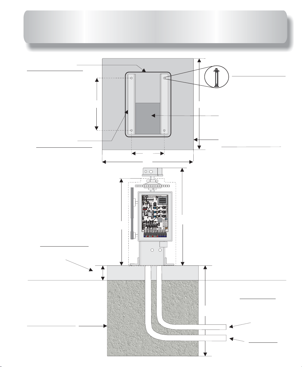
CIMIENTO DE CONCRETO PARA EL
CONCRETE PAD FOR SW-300
Cubierta plástica del
operador
Operator plastic
Cover
Chasis del
operador
Operator frame
Instalar 4” sobre
la tierra cuándo
sea posible
When possible
Install 4” above
Ground
3
/
13 ”
Tornillo de anclaje
4 lugares ½”X3 ½”
Four red head
Bolts
4
24”
Area for Conduit(s)
1
1
/2
X3
”
/2
”
Area para las pipas
de conducto
Cimiento de concreto
para el operador
9”
Operator Concrete
Pad
24”
514
514
N
GDE
GDE
ONO
ONON
00uF00 uF 2200uF2200uF 2200uF2200uF 2200u2200 u
514
GDE
ON
1
O
U
B
R
N
S
3
3
6
8
-----------------------OPEN------------------------
3
1234567812 34 56 78
1
O
U
B
R
N
S
3
3
6
8
P87C554SBAA
Cd2399Cd2399
TIG0505A
PHILIPSPHILIPS
3
PHILIPS
1
O
U
B
R
N
S
3
3
6
8
3
514514
GDE
23”
ONON
514514
514514
514514
514514
514514
514514
514514
N
N
N
GDE
GDE
GDE
GDE
GDE
GDE
GDE
ON
ON
ON
ON
ONO
ONO
ONO
25
1
/2
”
Cimiento de concreto
para el operador
Footing for
Gate operator
8
4”
24”
Conducto de bajo
voltage
Low voltage
Single Conduit for
Master/Slave
Conducto de alto
voltage
High voltage
conduit
Page 7
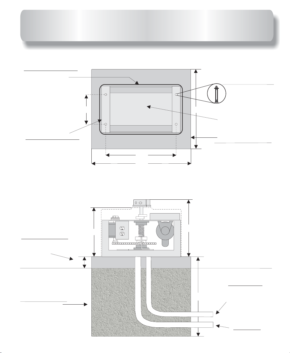
CIMIENTO DE CONCRETO PARA EL
CONCRETE PAD FOR SW-350
Cubierta plástica del
operador
Operator plastic
Cover
Tornillo de anclaje
4 lugares ½”X3 ½”
Four red head
1
/2
Bolts
X3
”
1
/2
”
Chasis del
operador
Operator frame
Instalar 4” sobre
la tierra cuándo
sea posible
When possible
Install 4” above
Ground
Cimiento de concreto
para el operador
Footing for
Gate operator
4”
9”
14
24”
Area for Conduit(s)
Area para las pipas
de conducto
Cimiento de concreto
para el operador
Operator Concrete
1
/2
21
”
30”
1
17 / ”
1
/2
”
4
Pad
Conducto de bajo
voltage
Low voltage
24”
Single Conduit for
Master/Slave
Conducto de alto
voltage
High voltage
conduit
9
Page 8
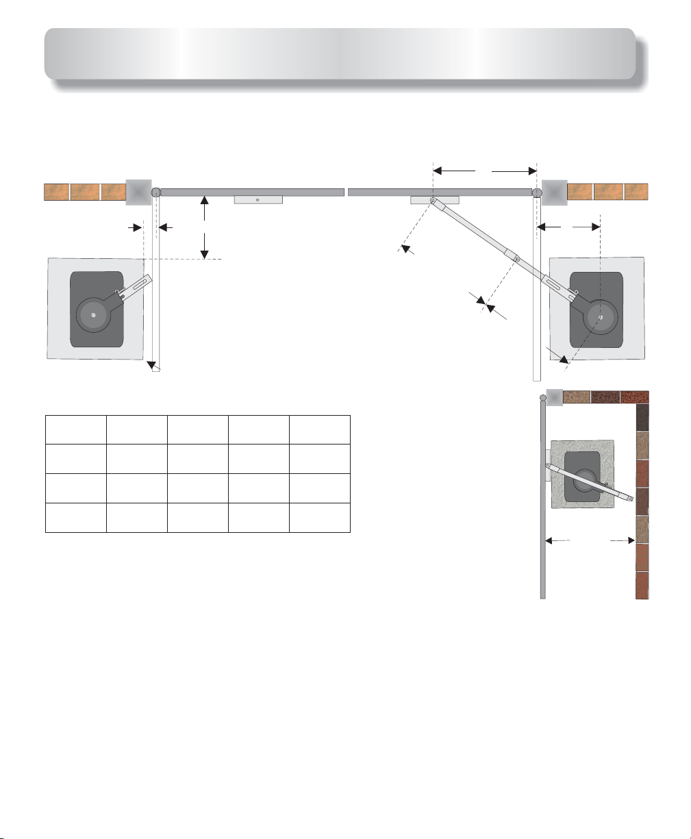
OPERATOR AND ARM DIMENTIONS
HINGE
CENTER
POST
OUTSIDE
A
This distance is from
the gate in open
position to edge of the
pad. Refer to .note
Gate
length
Less than
12”
13’-15’
16’-22’’
A
Dimentions Chart
: Is the distance between the gate bracket and the gate
2”
A
36”
42” 14”
48”
B
CONCRETE PAD
B
35”
41”
47”
C
14”
14”
Minimum
Distance
INSIDE
SECONDARY
34”
37”
40”
hinge point.
B
: Is the distance between the gate hinge point and the edge
of the concrete pad.
C
: Is the distance from the gate in the open position to the center
shaft of the operator.
Minimum distance
: Is the minimum distance required behind
the open gate. If the distance between the
open gate and the back wall is between 20”
and 33” refer to compact installation.
PRIMARY
C
Minimum
distance
Refer to
note
below.
Note: The 2” distance shown above is from the gate in the open position to the edge of the pad.
If the gate must open more than 90 degrees, the pad needs to move back accordingly. The
distance between the open gate and the pad needs to remain 2”. The distance “C” also needs to
move back accordingly if the opening is more than 90 degrees.
11
Page 9
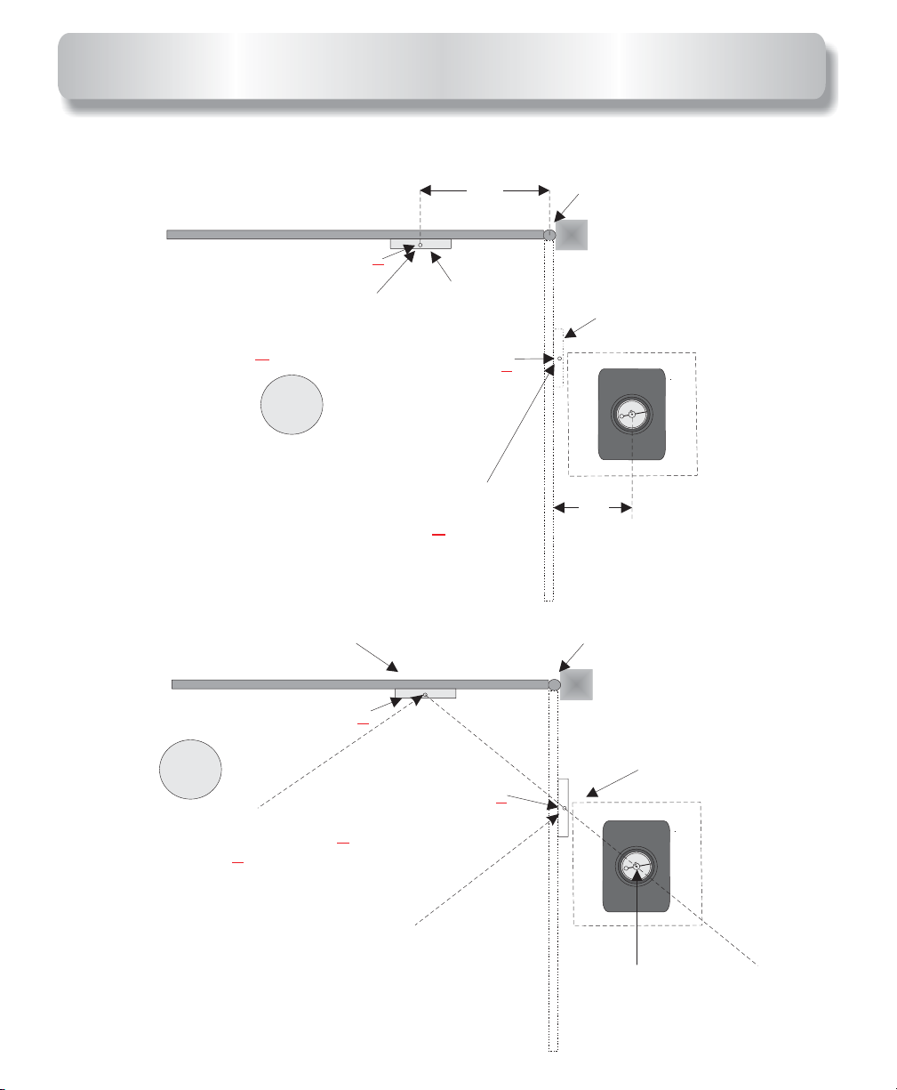
OPERATOR AND ARM LAYOUT
Out
In
Mark ground under
gate bracket with
gate closed. This will
be point Y
1
Mark ground under
gate open. This will
Out
In
Point Y
gate bracket with
be point Z
Bracket
Point Y
X
Bracket
X
“A”
Point Z
Hinge point
Bracket
X
14”
Hinge point
2
Draw a line from point past
the point as shown. This
should be laid on the ground.
The operators center shaft
goes on this line.
Z
Y
Point Z
Bracket
X
Center shaft of
Operator
13
Page 10
ARM LAYOUT & OPERATOR
PLACEMENT CONTINUED
Bracket
Point Y
3
Measure distance from the Y
And point Say distance is 60”,
divide this number by 2,which =30”.
This is the length of primary arm in
next drawing.
Z.
PLEASE BE EXACT!!!
point
Hinge point
X
Bracket
Point Z
This ARM section is half the
distance between point
and point as shown above.
IT MUST BE EXACT!!!
X
Center shaft of
Operator
Z
Y
This pipe does not need
to be measured after
primary arm is installed
this pipe makes up the
balance of arm.
4
+
CENTER OF
BOLT AT FIRST
HINGE POINT
PRIMARY ARM SECTION
+
CENTER OF
SHAFT ON
OPERATOR
15
Page 11

SWINGER COMPACT
INSTALLATON
To use this installation the gate must be 12’ or less.
HINGE
CENTER
OUTSIDE
INSIDE
27”
8”
Use these measurements, only if the
distance between the wall and the gate
in the open position is 20” to 34”. If you
have more than 34” refer to standard
installation.
SECONDARY
35”
20”
20” Minimum
17
Page 12

TORQUE LIMITER AND ARM
ADJUSTMENT
The torque limiter is shipped loose (not adjusted). You must use
a 20” pipe wrench to adjust the large torque limiter nut on the operator
as shown in the images below.
Tighten torque limiter nut until arm does not slip when the
operator is running.
Also run gate and grab gate at mid cycle to make sure torque
limiter will slip. This is an important adjustment, so please take your
time and do it right.
Torque limiter
adjusting nut.
Top view
20” Pipe wrench
3
2
1
514
514
N
GDE
GDE
ONO
ON
00uF00 uF 2200uF2200uF 2200uF2200uF 2200u2200u
514
GDE
ON
1
O
U
B
R
N
S
3
3
6
8
-----------------------OPEN------------------------
3
12345678123 4 5 6 7 8
1
O
U
B
R
N
S
3
3
6
8
P87C554SBAA
Cd2399
TIG0505A
PHILIPSPHILIPS
3
PHILIPS
1
O
U
B
R
N
S
3
3
6
8
3
514
GDE
ONON
514
514
514
514
514
514
514
N
N
GDE
GDE
GDE
GDE
GDE
GDE
GDE
ON
ON
ON
ON
ON
ONO
ONO
Torque limiter
adjusting nut.
Side view
514
514
GDE
GDE
ON
ON
00uF00uF 2200uF2200uF 2200uF2200uF 2200u2200u
514
N
GDE
ONO
1
O
U
B
R
N
S
3
3
6
8
-----------------------OPEN-----------------------------------------------OPEN------------------------
3
123456781 2 3 4 5 6 7 8
1
O
U
B
R
N
S
3
3
6
8
P87C554SBAAP87C554SBAA
Cd2399
TIG0505A
PHILIPS
3
PHILIPS
1
O
U
B
R
N
S
3
3
6
8
3
514
N
GDE
ONO
514
514
514
514
514
514
514
GDE
GDE
GDE
GDE
GDE
GDE
GDE
ON
ON
ON
ON
ON
ON
ON
SW-300
MASTER
SW-350
ARM ADJUSTMENT:
a bolt to hold the arm lever in closed
position. With the arm lever closed
tighten the arm adjusting screw as tight
as possible.
ARM QUICK RELEASE:
arm with the quick release, simply
remove the bolt or padlock from the arm
lever and open it. Opening the arm lever
will allow you to manually open the gate.
Arm adjusting
screw
Allen wrench
Use a pad lock or
To release the
19
Page 13

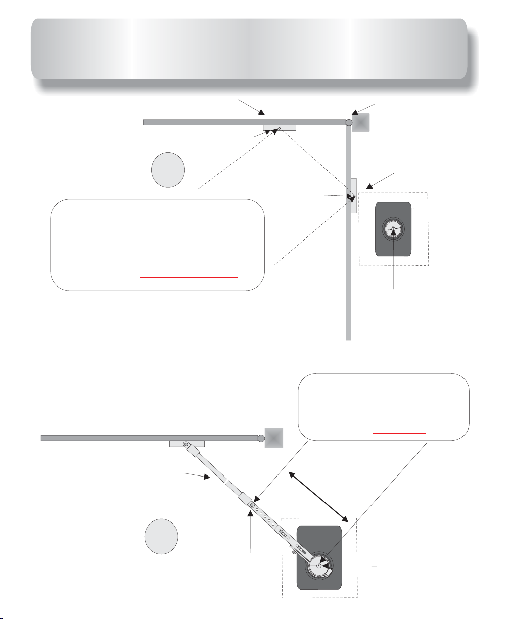
GATE TRAVEL ADJUSTMENT
Locate limit switch.
Step 1: Turn the on operator.
Step 2: Use an allen wrench to loosen up the limit cams. Turn the limit
Cams to desired direction.
Step 3: tighten the allen screw.
Step 4: Turn the operator back on.
Step 5: Run gate operator. If more adjustment is needed, repeat
the steps.
power off
Limit switches
Limit cams
Allen wrench
21
Page 14

LEFT HAND OPENING
SETTINGS
See chart below for specific operator model wiring direction.
514
514
514
514
514
514
514
GDE
ON
GDE
GDE
ON
ON
GDE
GDE
ON
ON
GDE
GDE
ON
ON
IMPORTANT:
This setting is for
left hand opening.
Be sure to follow the
wire sequence as the
two Swinger models
are the opposite of
each other.
24
Use these wire settings for SW-300 & SW-350 opening direction
Limit wires
Motor wires
SW-300 SW-300
C-LIMIT = wireBlue MOT-CLOSE = wireBlue
O-LIMIT = wireRed MOT-OPEN = wireRed
SW-350
C-LIMIT = wireRed MOT-CLOSE = wireRed
O-LIMIT = wireBlue MOT-OPEN = wireBlue
SW-350
Opening to the left
.
Page 15

RIGHT HAND OPENING
SETTINGS
See chart below for specific operator model wiring direction.
514
514
514
514
514
514
514
GDE
ON
GDE
GDE
ON
ON
GDE
GDE
ON
ON
GDE
GDE
ON
ON
IMPORTANT:
This setting is for
right hand opening.
Be sure to follow the
wire sequence as the
two Swinger models
are the opposite of
each other.
Use these wire settings for SW-300 & SW-350 opening direction
Limit wires
Motor wires
SW-300 SW-300
C-LIMIT =
O-LIMIT =
Blue wire
MOT-CLOSE =
MOT-OPEN =
SW-350
C-LIMIT = MOT-CLOSE =
O-LIMIT = MOT-OPEN =
Opening to the right
Red wire
.
Red wireRed wire
Blue wire
SW-350
Blue wireBlue wire
Red wire
25
Page 16

ELECTRICAL CONNECTION
OPERATORS BE PROPERLY GROUNDED!MUST
Power switch and
electrical connection
box.
For power, a minimum
of a 20-Amp dedicated
circuit breaker is
needed.
OFF
THIS
A
C
NDSERVICED
THISUN
LO
U
SEW
NIT
WA
TE
IT
MUSTBE
ITHO
CHN
WILLOPE
R
N
UT
BY
ICIAN.
I
N
WARN
CERTIFIED
IN
G
ST
N
AND
ALLE
IN
G
D
S
D
U
IS
E
I
T
C
L
A
E
O
B
C
S
N
L
T
E
N
E
R
R
D
E
F
I
V
C
C
A
O
I
O
T
C
N
S
R
N
IN
P
H
G
L
O
O
O
G
Y
E
U
W
C
R
T
U
K
E
OFF
D
N
R
H
O
I
T
A
B
O
Z
E
R
A
F
U
R
O
S
D
R
E
E
For power wires enclosure
use UL listed conduits.
Connect black wire to 115 volts AC = Hot.
Connect white wire to AC = Neutral.
Connect ground wire to operator metal
frame. Use a proper for a
ground rod
ground reference.
Use the shortest and thickest wire possible
for ground.
All gate operators be properly grounded.
A proper ground in a gate operator installation minimizes or prevents damage from an electrical
charge, such as a near lightning strike or an electrical static discharge.
.
Use a single wire for the ground. splice two wires for the ground. If the wire breaks or is
cut, replace it with a single length. use two wires for the ground.
Check with your City code for proper earth ground rod type and proper grounding procedures.
MUST
DO NOT
NEVER
27
Page 17

WIRED IN
SERIES
TWISTED 6
TURNS
PER FOOT
SWINGER LOOP LAYOUT
Outside Safety loopOutside Safety loop
5FT5
FT
5FT5
FT
FT
5FT5
1/4 IN1/4 IN
Gate in open
Gate in open
position
position
Center Phantom loopCenter Phantom loop
FT
5FT5
5FT5
FT
Inside Safety loopInside Safety loop
5FT5
FT
1 1/2 IN
Exit loopExit loop
WHEN USED
This is a normal loop layout. Remember when connecting to
an All-O-Matic circuit board you use the
contacts normally
open contacts
for your safety loop detector and
from the exit loop. You must twist your
normally closed
wires from your exit point of the saw cut all the way to the
circuit board, no exceptions.
29
Page 18

ACCESSORY CONNECTIONS
The circuit board output provides up to 700 mAmps of power for
24-VAC
accessories. More than two or three accessories will require a separate
power supply.
514
514
514
514
514
514
EXIT Loop
Detector
Keypad or
Telephone
Power
Detect
SENS.
LEVELLEVEL
BOOSTONBOOSTON
PULSE
FREQ.
Loop FailLoop Fail
Reset
C
514
GDE
ON
GDE
GDE
ON
ON
GDE
GDE
ON
ON
C
C
1 2 3 4 5 6
0
2
0
1
OFF
PRES
0
2
0
1
ABC
DEF
1
2
3
GHI
JKL
MNO
4
5
6
PQRS
TUV
WXYZ
7
8
9
TONE
OPER
*
#
0
C
GDE
GDE
ON
ON
Remove black jumper
from SAFETY when
Power
Detect
SENS.SENS.
LEVEL
BOOSTON
PULSE
FREQ.
Loop FailLoop Fail
Reset
a safety device is
1 2 3 4 5 6
0
2
0
1
OFF
PRES
0
2
0
1
SAFETY Loop
installed.
Detector
AB
PHOTO Beam
C
Push Button or
Fire Box
Card Reader or
Key Switch
C
C
C
= 24V-COM
C
Power
Detect
PHANTOM Loop
1 2 3 4 5 6
0
2
SENS.
LEVELLEVEL
1
0
BOOSTON
OFF
PULSE
PRES
0
2
FREQ.
0
1
Loop FailLoop Fail
Reset
Detector
See page 33 for
connection of safety
device wiring diagram.
31
Page 19

MULTIPLE SAFETY DEVICES
CONNECTIONS
Multiple devices installed together must be connected .
the normally closed (N.C.) dry contact from accessory relay. efore
each Also, b
installing the accessory devices, remove the black wire jumper from the
terminal position
on the terminal strip of the control board.
in seriesSAFETY “ ”
Locate
SAFETY
Safety wire connections
From Accessory #1 to Terminal Strip
Relay Com to 24V-COM
From Accessory #1 to Accessory # 2
Relay N.C. To Relay Com
514
514
GDE
GDE
ON
ON
Terminal strip
From Accessory #2 to Terminal Strip
Relay N.C. to SAFETY
514
514
514
514
514
GDE
ON
GDE
GDE
ON
ON
GDE
GDE
ON
ON
Remove black jumper
Relay (COM)
Relay (N.C.)
from SAFETY when
a safety device is
installed.
SAFETY Loop
detector
PHOTO
Beam
Power
Detect
1 2 3 4 5 6
0
2
SENS.
LEVEL
1
0
BOOSTON
OFF
PULSE
PRES
0
AB
FREQ.
Loop FailLoop Fail
ResetReset
2
0
1
Relay (COM)
Wire nut
Relay (N.C.)
This diagram is for the relay wires of the safety devices, two wires to the terminal
strip (one from each device) and two wires to the orange wire nut.
33
Page 20

LEADING EDGE CONNECTION
GDE
514
GDE
514
GDEGDE
514
N
S
N
S
N
3
R
3
U
8
O
6
ON
ON
GND
EDGE
u
2200u2200
uF
2200uF2200
uF
00uF00 uF 2200 uF2200
GDE
514
ON
GDE
514
ON
B
1
3
-----------------------OPEN-----------------------------------------------OPEN------------------------
123456 781 2 3 4 5 6 7 8
GDE
514
ON
S
3
R
3
R
3
3
U
U
8
8
O
O
6
6
B
B
1
3
1
3
PHILIPSPHILIPS
PHILIPS
GDEGDE
514
ON
Connect one of the wires from leading edge to
connector
on control board.
Connect the other wire from leading edge to
connector control .
on board
ON
GDEGDE
514
ON
GDEGDE
514
ON
GDEGDE
514
ON
GDEGDE
514
ON
GDEGDE
514
ON
GDEGDE
514
ON
GND
EDGE
LEADING EDGE SENSOR
35
Page 21

PRE-WIRED LOOP INSTALLATION
ON SW-350
Model SW-350
provides three pre-wired loop harnesses one for SAFETY
LOOP one for PHANTOM and one for EXIT LOOP. Loop detectors must be
120 VAC.
To install loop detectors make sure power is off in main power source then
simply plug detector in designated harness socket and wire the ground loop
to the grey and brown wires located inside the electrical box behind operator
gearbox. There is one pair labeled EXIT for EXIT LOOP one PHANTOM for
PHANTOM LOOP and one SAFETY for SAFETY LOOP.
IMPORTANT:
Use different frequencies for every loop detector.
IMPORTANT: When using the safety loop, you must remove the jumper from
“SAFETY” on terminal strip.
Twisted wires must be 6 turns
per foot MINIMUM
Loop harness
Sockets
EXIT LOOP
EXIT
Look for wires
EXIT
labeled in
the electrical box
EXIT
115VAC
SAFETY
LoopFailLoopFail
SENS.
BOOSTONBOOSTON
PULSE
FREQ.
Reset
LEVEL
DetectDetect
Power
2
100
1 2 3 4 5 6
00OFF
PRES21
LoopFailLoopFail
SENS.
BOOSTONBOOSTON
PULSE
FREQ.FREQ.
Reset
LEVELLEVEL
Detect
PowerPower
2
100
1 2 3 4 5 6
00OFF
PRES21
SAFETY
SAFETY LOOP
Look for wires
labeled in
SAFETY
the electrical box
37
Page 22

EMERGENCY RELEASE
For SW-350
Procedures to release gate:
1. Turn power OFF.
2. Push pedal down & move pedal
to hold pedal down in position
3. Push gate open.
s
lightly to the right
.
EXIT
T
T
T
A
E
A
E
A
E
G
O
G
O
G
O
P
P
C
P
C
C
I
I
I
E
E
E
T
T
T
R
R
R
A
A
A
A
A
A
T
M
T
M
T
M
O
O
O
O
O
O
T
R
T
T
R
R
S
S
S
U
U
U
A
A
A
®
S
S
S
S
S
S
L
L
L
D
D
D
I
I
I
D
D
D
A
A
A
E
E
E
E
E
E
R
R
R
H
H
H
S
S
S
R
R
R
E
E
E
•
•
•
V
V
V
S
S
S
O
O
O
W
W
W
•
•
•
I
I
I
N
N
N
S
S
S
G
G
G
R
R
R
E
E
E
115VAC
SAFETY
39
Page 23

Terminal
strip
THREE BUTTON STATION
SYSTEM
See push button connections below.
514
514
514
514
514
514
514
GDE
ON
GDE
GDE
ON
ON
GDE
GDE
ON
ON
GDE
GDE
ON
ON
PED-SW
Jumper
COM
OPEN
CLOSE
STOP
N.O.
N.O.
N.C.
Connect the from all the
push buttons to on the
COMMON
24V- COM
terminal strip.
Connect push button
contact to on the terminal
OPEN N.O.
EXIT LOOP
strip.
Connect push button
contact to on the terminal strip.
Connect push button
Contact to on the terminal
strip and remove Jumper.
CLOSE N.O.
3BT
STOP N.C.
PED-SW
PED-SW
41
Page 24

MASTER/SLAVE CONNECTION
Before connecting master/slave gate operators together, test and adjust limit
switches and the ERDs for each operator as “ ” machines. All
stand alone
the
accessories must be installed on the master board, no exception.
See page 53 for dip switch settings.
Use a two wire and run it through a UL listed conduit for
shielded cable
master/slave connection. Follow the wiring diagram as shown below.
Master Board Slave Board
+.....................Positive to Positive...................+
-...................Negative to Negative...................-
Connect shield to
Use UL listed
conduit
slave metal frame
only.
Shielded
cable
ON
514
GDE
ON
514
GDE
ON
514
GDE
ON
514
GDE
ON
514
GDE
ON
514
GDE
43
Page 25

MAGNETIC/SOLENOID LOCK
CONNECTIONS
Magnetic lock installation requires a step down transformer with appropriate
voltage for the specific lock accessory.
AC-N LOCK
and from terminal strip supply 110 volts to power the transformer
and control the locks’. Connect low voltage wires from transformer directly to
the lock as shown below. Only two wires needed for the installation. No relay
wires required.
514
514
514
514
514
514
514
GDE
ON
GDE
GDE
ON
ON
GDE
GDE
ON
ON
GDE
GDE
ON
ON
SOLENOID
LOCK
MAG
LOCK
For MAGNETIC LOCK set “ ” Dip
Switch to the “ ” Position.
ON
For SOLENOID LOCK set “ ” Dip
Switch to the “ ” Position.
OFF
LOCK
LOCK
Step Down
Transformer
OFF ON
TIMER
RADIO
OSC
LOCK
1-PASS
SLAVE
BRAKE
SPARE
-----------------------OPEN------------------------
1 234 56 781 2 3 4 5 6 7 8
45
Page 26

RADIO RECEIVER CONNECTIONS
3 wire receiver mounts on receiver strip outside control box as shown
below.
4 wire receiver :connect the two grey wires to & terminals on receiver
strip outside control box. Connect black wire to and red wire
to on main board terminal strip as shown below.
24VAC control
3 wire 24VAC
Radio Receiver
Multi-Code
GDE
514
ON
GDE
514
ON
GDE
514
ON
GDE
514
ON
3 = 24V
2 = Relay
1 = Common
3
2
1
12
24 V-COM
Receiver terminal strip
located outside control
box.
4 wire 24VAC
Radio Receiver
47
Page 27

OPEN AND CLOSE ELECTRONIC
REVERSING SENSOR(ERDs)
ADJUSTMENT
Open and Close ERD
SENSITIVITY
MAX MAXMIN MIN
GDE
514
N
S
N
S
N
3
R
3
U
8
O
6
B
1
u
2200u2200
uF
00uF00 uF 2200 uF2200uF 2200uF2200
GDE
514
ON
GDE
514
ON
3
-----------------------OPEN------------------------
123456 781 2 3 4 5 6 7 8
GDE
514
ON
S
3
R
3
R
3
3
U
U
8
8
O
O
6
6
B
B
1
3
1
3
PHILIPSPHILIPS
PHILIPS
GDE
514
ON
GDE
514
ON
GDE
514
ON
GDE
514
ON
GDE
514
ON
GDE
514
ON
GDE
514
ON
ON
N
S
3
R
3
U
8
O
6
B
1
3
N
S
3
R
3
U
8
O
6
B
1
3
Counter clockwise maximum
sensitivity
2
1
3
4
Set these pins for different motors
using the chart below
Motor Rating chart
Model
SL-100
SW-300
OH-200
SL-150
SL-150
SL-150
SW-350
SW-350
HP Rating
1/2
1/2
1/2
1/2
3/4&1
1
½
3/4&1
# of Caps
1
1
1
2
2
3
1
2
Clockwise minimum sensitivity
When gate stops and reverses by itself,
the ERD is .
The gate must
too sensitive
stop and reverse when it
hits an obstruction or the ERD is
not sensitive enough.
ERD’S must be adjusted
by qualified technician.
Pin #
3
3
3
4
1
2
3
1
The gate operator ERDs must be
adjusted so that the gate provides
regular, reliable and safe cycles.
ERD must be checked every six
months.
49
Page 28

TIMER ADJUSTMENT
TIMER ON: Timer to close, can be set from 1 to 60 seconds.
TIMER OFF: Gate operation is push button to open, push button to close.
TO TIMER:
OVERRIDE THE Turn the RADIO switch to the “ON” position.
This will allow the radio receiver to close the gate before the timer.
TIMER adjustment
Turn potentiometer counter clockwise for more
60
Sec
0
Sec
time.
60
Sec
TIMER “ ” to activate
0
Sec
ON
the timer
RADIO “ ” =ON Allows
the transmitter to close
the gate before the timer.
Turn potentiometer clockwise for less time.
Timer Pot
60 Sec. 1 Sec.
N
S
3
R
3
U
8
O
6
B
1
3
OFF ON
-----------------------OPEN------------------------
TIMER
RADIO
OSC
LOCK
1-PASS
SLAVE
BRAKE
SPARE
1 234 56 781 2 3 4 5 6 7 8
GDE
514
N
S
N
S
N
3
R
3
U
8
O
6
B
1
u
2200u2200
uF
2200uF2200
uF
2200uF2200
uF
00uF00
GDE
514
ON
GDE
514
ON
3
-----------------------OPEN-----------------------------------------------OPEN------------------------
123456 781 2 3 4 5 6 7 8
GDE
514
ON
S
3
R
3
R
3
3
U
U
8
8
O
O
6
6
B
B
1
3
1
3
PHILIPSPHILIPS
PHILIPS
GDE
514
ON
GDE
514
ON
GDE
514
ON
GDE
514
ON
GDE
514
ON
GDE
514
ON
GDE
514
ON
ON
51
Page 29

DIP SWITCH FUNCTIONS
OFF ON
TIMER
-----------------------OPEN------------------------
1 234 56 781 2 3 4 5 6 7 8
TIMER ON
51
switch “ ” activates the TIMER. See page
for details.
RADIO
OSC
LOCK
RADIO ON
to override the timer. See page for details.
switch “ ” allows the radio receiver
1-PASS
OSC ON
SLAVE
BRAKE
SPARE
This function is to change from solenoid position in the “ ” position to magnetic
lock in the “ ” position. The terminal position marked “LOCK” on the circuit
board provides 115 volts for the each type of locks. Use appropriate step down
transformer for specific locks. Refer to page for connections and settings.
This is a true one pass anti-tailgating feature. This feature may only be used with
safety loops. With this switch in the “ ” position, the gate will open until one car
passes the safety loops then it will stop and close. If a second car pulls on the loop
the gate will stop the car must then back off the loop before the gate will close.
ON
,
switch “ ” allows the radio receiver to
top and reverse the gate n any direction.
s i During a
cycle the first a
reverses
signal stops gate, second signal
gate.
LOCK
45 lock
1-PASS
ON
TIMER
RADIO
51
OSC
OFF ,
SLAVE
This feature is used on master/slave setups. Set slave switch “ ” on slave
machine, all other switches “ ”. Set slave switch to the “OFF” position on
master machine. Set other function switches on master machine as desired. See
page for more details on master/slave connections and settings.
The BRAKE helps the gate to stop at the precise moment of contact of the limit
nuts with the limit switches. This function should only be used when an uphill or
downhill installation is required. Replace the 15 Amps fuse with a 20 Amps fuse
when this function is used.
43
OFF
BRAKE
SPARE NOT USED
ON
53
Page 30

SWINGER ARM PARTS
QUICK
RELEASE ARM
3 SET
SCREWS
PIPE KNUCKLES
PIPE ARM
3 SET
SCREWS
GATE BRACKET
HUB
54
PRIMARY
FLAT BAR
T
T
A
T
E
A
E
A
E
G
O
G
O
G
O
P
P
C
P
C
C
I
I
I
E
E
E
T
T
T
R
R
R
A
A
A
A
A
A
T
M
T
M
T
M
O
O
O
O
O
O
T
R
T
T
R
R
S
S
S
U
U
U
A
A
A
®
S
S
S
S
S
S
L
L
L
D
D
D
I
I
I
D
D
D
A
A
A
E
E
E
E
E
E
R
R
R
H
H
H
S
S
S
R
R
R
E
E
E
•
•
•
V
V
V
S
S
S
O
O
O
W
W
W
•
•
•
I
I
I
N
N
N
S
S
S
G
G
G
R
R
R
E
E
E
Page 31

ALL-O-MATIC’S good service and high quality by years of, proven
reliability place the ALL-O-MATIC Swing gate operators ahead of the
competition. The SW-350 is our highest duty rated operator and the
most powerful continuous duty operator available in the market today.
The SW-350 has a foot pedal release in the event of a power failure.
The SW-300 is our most popular gate operator. It is continuos duty for
light commercial and residential use. In the event of power failure, the
gate can be released open with a quick release arm. A battery back up is
also available on the SW-300.
El buen servicio, la alta calidad y los años de la confiabilidad probada de
ALL-O-MATIC, colocan a los operadores batibles, delante de la
competencia. El SW-350 es nuestro operador con la capacidad más alta
y el operador más potente de uso continuo disponible en el mercado
hoy. El SW-350 cuenta con un pedal de pie para liberación del portón en
el acontecimiento de un apagón. El SW-300 es nuestro operador más
popular. Está clasificado para uso continuo comercial y residencial. En
el evento de un apagón, puede abrir el portón con un brazo de
liberacion rapida. Un respaldo de bateria esta tambien disponible en el
SW-300.
ALL-O-MATIC INC
Northridge, CA 91324
WWW.ALLOMATIC.NET
 Loading...