

Page 1

The 760 Operator and
450 MPS Control Panel:
Installation Manual
Contents
Important Safety Information............................................................ 2
Technical Data............................................................................... 4
The 760 Operator............................................................................ 4
The Control Panel...........................................................................4
Unpacking the Operator................................................................... 5
The 760 Swing Gate Operator........................................................... 6
General Characteristics.................................................................... 6
450 MPS Logic Modes .................................................................... 6
Installation Instructions.................................................................... 9
Preparing the Gate .......................................................................... 9
Manual Release.............................................................................10
Installing the 760 Operator ..............................................................10
Install the Load Bearing Box............................................................10
Secure the Load Bearing Box...........................................................11
Install the Gate Leaf Shoe................................................................11
Install the Gate Leaf.......................................................................14
Install the Operator in the Load Bearing Box......................................14
Install the 450 MPS Control Panel ....................................................16
Connect the Main Power Supply……………………………………..16
Connect the Operator(s) to the Control Panel………………………..17
Check the Motor's Direction of Rotation……………………………..19
Connect Other Devices……………………………………………….19
Set Operating Controls………………………………………………..21
Fine-tune the Bypass Valve Pressures...............................................22
Adjust the Beginning of the Braking Phase ........................................23
Adjust the Braking Intensity ............................................................23
Assemble and Install the Manual Release ..........................................23
Installing an Extension Arm.............................................................25
Maintenance.................................................................................26
The 760 Operator...........................................................................26
The Control Panel..........................................................................26
Troubleshooting ............................................................................27
Exploded View, 760 Splined Shaft....................................................28
Exploded View, 760 CBAC-SB-SBS.................................................29
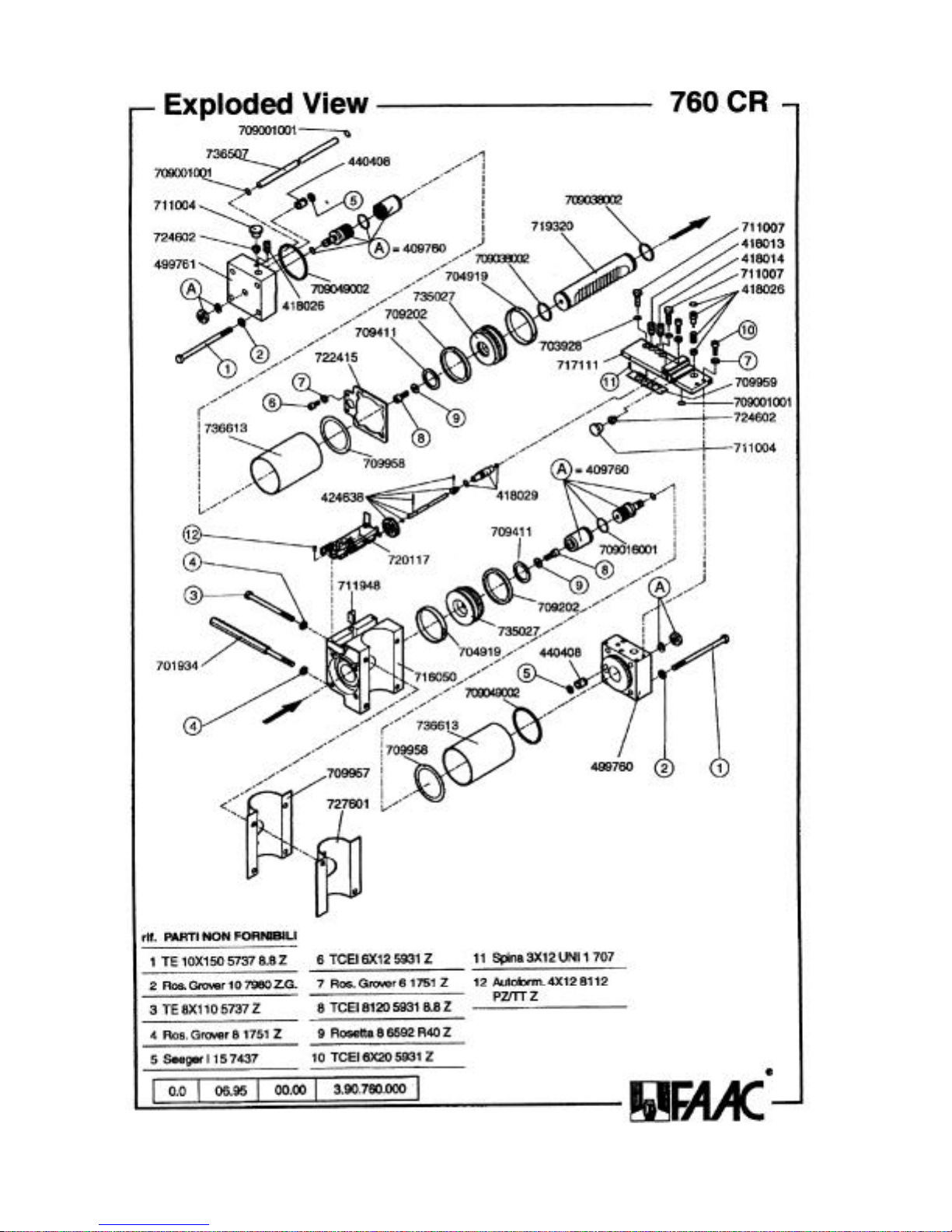
Exploded View, 760 CR..................................................................30
Page 2

Important Safety Information
Both the installer and the owner and/or operator of
this system need to read and understand this
installation manual and the safety instructions
supplied with other components of the gate system.
This information should be retained by the owner
and/or operator of the gate.
WARNING! To reduce the risk of injury or death
1 . R E A D A N D F O L L O W A L L
I N S T R U C T I O N S .
2. Never let children operate or play with
gate controls. Keep the remote control
away from children.
3. Always keep people and objects away
from the gate. NO ONE SHOULD
CROSS THE PATH OF THE
MOVING GATE.
4. Test the gate operator monthly. The
gate MUST reverse on contact with a
rigid object or stop when an object
activates the non-contact sensors. After
adjusting the force or the limit of travel,
retest the gate operator. Failure to
adjust and retest the gate operator
properly can increase the risk of injury
or death.
5. Use the emergency release only when
the gate is not moving.
6. KEEP GATES PROPERLY
MAINTAINED. Read the owner’s
manual. Have a qualified service person
make repairs to gate hardware.
7. The entrance is for vehicles only.
Pedestrians must use separate entrance.
8. SAVE THESE INSTRUCTIONS.
When installing the photo-beams supplied with this unit
two things need to be considered.
1. Care should be exercised to reduce the risk of
nuisance tripping, such as when a vehicle, trips
the sensor while the gate is in motion.
2. One or more photobeams shall be located
where the risk of entrapment exists, such as the
perimeter reachable by the moving gate leaf.
Gate Design
1. A gate is a potential traffic hazard, so it is important
that you locate the gate far enough away from the
road to eliminate the potential of traffic getting
backed up. This distance is affected by the size of
the gate, how often it is used, and how fast the gate
operates.
2. The operator you choose to install on your gate
must be designed for the type and size of your gate
and for the frequency with which you use the
operator.
3. Your gate must be properly installed and must work
freely in both directions before the automatic
operator is installed.
4. An automatic operator should be installed on the
inside of the property/fence line. Do not install the
operator on the public side of the property/fence
line.
5. Pedestrians should not use a vehicular gate system.
Prevent such inappropriate use by installing
separate gates for pedestrians.
6. Exposed, reachable pinch points on a gate are
potentially hazardous and must be eliminated or
guarded.
7. Outward swinging gates with automatic operators
should not open into a public area.
8. The operating controls for an automatic gate must
be secured to prevent the unauthorized use of those
controls.
9. The controls for an automatic gate should be
located far enough from the gate so that a user
cannot accidentally touch the gate when operating
the controls.
10. An automatic gate operator should not be installed
on a gate if people can reach or extend their arms or
legs through the gate. Such gates should be guarded
or screened to prevent such access.
Installation
1. If you have any question about the safety of the
gate operating system, do not install this operator.
Consult the operator manufacturer.
2. The condition of the gate structure itself directly
affects the reliability and safety of the gate
operator.
3. Only qualified personnel should install this
equipment. Failure to meet this requirement could
cause severe injury and/or death, for which the
manufacturer cannot be held responsible.
2
Page 3

4. The installer must provide a main power switch that
meets all applicable safety regulations.
5. Clearly indicate on the gate with the 2 warning
signs that are included (visible from either side of
the gate).
6. It is extremely unsafe to compensate for a damaged
gate by increasing hydraulic pressure.
7. Devices such as reversing edges and photocells
must be installed to provide better protection for
personal property and pedestrians. Install reversing
devices that are appropriate to the gate design and
gate application.
8. Before applying electrical power, be sure that the
voltage requirements of the equipment correspond
to your supply voltage. Refer to the label on your
operator system.
Use
1. Use this equipment only in the capacity for which it
was designed. Any use other than that stated should
be considered improper and therefore dangerous.
2. When using any electrical equipment, observe some
fundamental rules:
• Do not touch the equipment with damp or
humid hands or feet.
• Do not install or operate the equipment
with bare feet.
• Do not allow small children or incapable
persons to use the equipment.
3. If a gate system component malfunctions, turn off
the main power before making any attempt to repair
it.
4. Do not attempt to impede the movement of the gate.
You may injure yourself as a result.
5. This equipment may reach high temperatures
during operation; therefore, use caution when
touching the external housing of the operator.
6. Learn to use the manual release mechanism
according to the procedures found in this installation manual.
7. Before carrying out any cleaning or maintenance
operations, disconnect the equipment from the
electrical supply.
8. To guarantee the efficiency of this equipment, the
manufacturer recommends that qualified personnel
periodically check and maintain the equipment.
U.L. Class and FAAC Operator
Model
Class I: Residential Vehicular Gate Operator
402 750
422 760
412 400
620 640
Duty Cycle Typical Use
Limited duty • Home use
• Small apartment building, for example, up to 4 units
in a building, with limited public access
Class II: Commercial/General Access Vehicular Gate Operator
400 640
620
Continuous duty • Apartment buildings
• Very public access
Class III: Industrial/Limited Access Vehicular Gate Operator
400 640
Continuous duty • No public access
620
Class IV: Restricted Access Vehicular Gate Operator
620 640 Continuous duty • Prison rated security
3
Page 4

Technical Data
The 760 Operator
Parameter 760 Standard 760 Longer Leaf
Ambient temperature, deg F
(deg C)
Maximum duty cycle, cycles per
hour.
Thermal cut out, deg F (deg C) 212 (100)
Power voltage required, VAC* 115, ±10% or 230, +6 or -10%, 60 Hz* 230, +6 or –10%,
Absorbed power, W 220
Current drawn, A 230VAC= 1A, 115VAC= 1.5A 0.8A
Motor speed, rpm 1400 960
Type of oil Lubrication Engineers – MONOLEC 6105
Height (excluding spline) ×
width × depth, in. (cm)
Weight, lb (kg) 281/2 (13)
Oil quantity, qt (l) 11/4 (1.2)
Hydraulic locking Opened and closed Not available Not available
Maximum gate weight, lb (kg) 1760 (800)
Maximum gate length, ft (m) 7 (2.1) 10 (3) 13 (4)
Maximum angle of rotation, deg 148 degrees
90-deg opening time, sec 12** 17**
Nominal torque, ft-lb (Nm) 399 (543) 200 (272)
* Your standard 220 VAC power source meets the specification for 230 VAC, +6 or -10%.
** Plus additional time for soft-stop versions
-4 to 131 (-20 to 55)
30
61/4 × 101/4 × 191/4
(15.9 × 26 × 49)
760 Extra Long
Leaf
The Control Panel
The 760 Operator must be installed with a 450 MPS
control panel to be a U.L. recognized installation. The
450 MPS can be used to control a single 760 operator or
a dual (biparting) system. Both the control panel and
the operator must use the same power supply voltage.
The 450 MPS
To determine the voltage requirement of your 450 MPS
control panel, refer to the label on the transformer of the
control panel:
Label reads: 1450MPSUS = 220 VAC
1450MPSUS115 = 115 VAC
Operating logics available: E, EP, A, S, B, and C
(See pages 6, 7, & 8)
4
Page 5
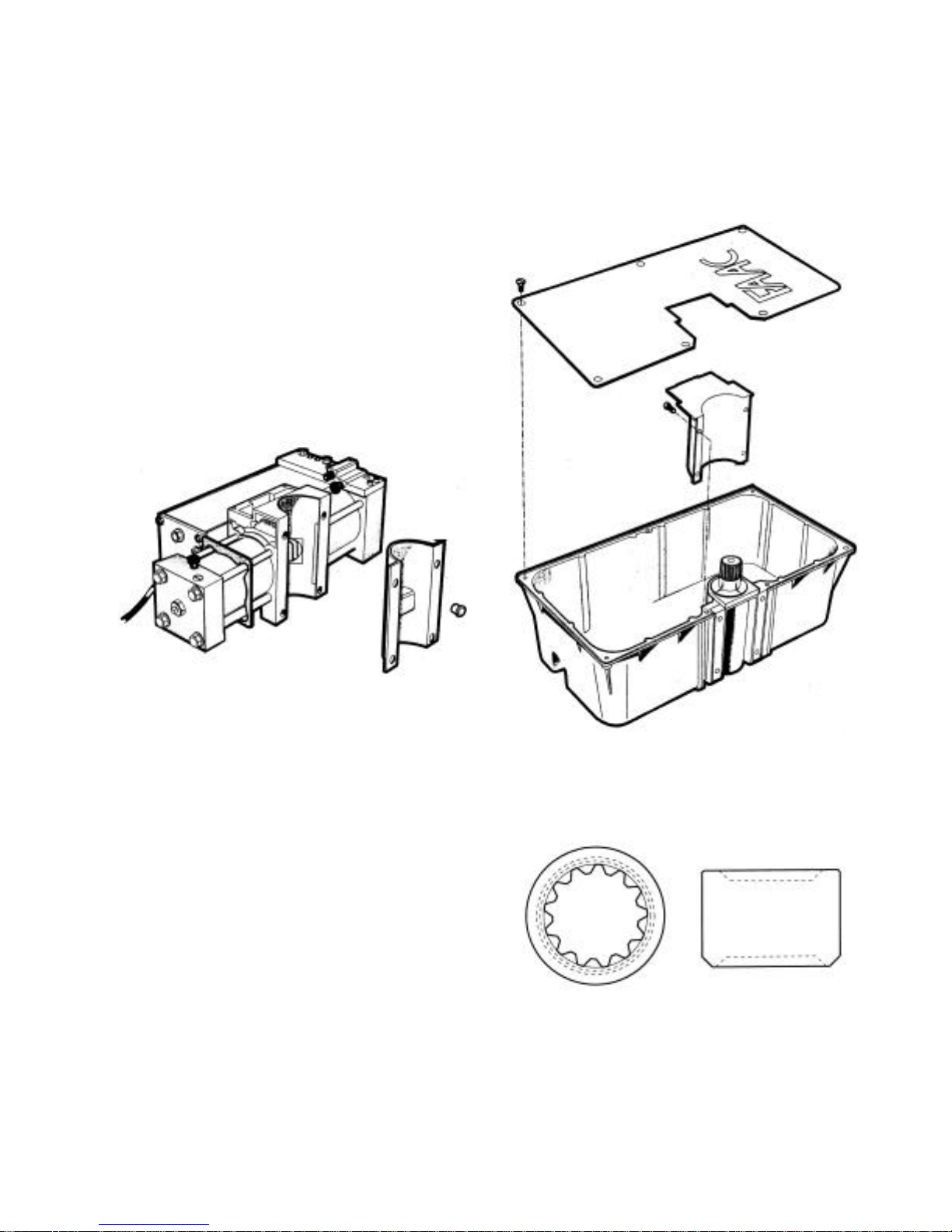
Unpacking the Operator
When you receive your 760 Operator, inspect the
shipping boxes for physical damage such as leaking oil
or a torn carton. Then inspect the operator, the mounting
box, and the control panel after you remove them from
the boxes. Notify the carrier immediately if you note
any damage because the carrier must witness the
damage before you can file a claim.
As you unpack the boxes, insure that all the parts listed
below are included.
760 Operator:
Load Bearing Box:
Figure 1. Hydraulic pump/ drive assembly with
a plastic shipping cover fitted over the rack.
Package containing:
• 4 bolts and 4 lock washers for attaching
the 760 Operator to the load bearing box.
• 1 unassembled Manual Release housing
and its necessary screws and nuts.
• 1 brass rod with a plastic gear and a
second brass gear assembly with key,
spacer, and disc for limiting access to one
side.
Figure 2. Cast aluminum box with stainless
steel lid; inside, a pinion cover is attached to
the box with 4 screws.
Figure 3. The Splined Collar, which comes on
the shaft of the Load Bearing Box, attaches to
the gate.
5
Page 6

The 760 Swing Gate Operator
General Characteristics
The 760 Operator with G e n t l e S w i n g
Management is a medium-duty operator designed to
swing a gate leaf from an unobtrusive in-ground
installation, thus preserving the appearance of the gate.
A 760 Operator system consists of a hydraulic unit in an
in-ground box and a control panel.
The 760 Operator is designed for gates swinging open
up to a maximum of 148 degrees with a 90-deg opening
time of either 12 or 18 sec (see Technical Data on page
3), depending on the model. The soft-stop versions of
the 760 Operator brake the movement of the gate during
the last 10 deg of swing in both the opening and closing
directions provided the gate opens 90 deg or more.
Once installed, the 760 Operator can be removed from
the load bearing box without having to remove the gate.
For all models, the axis of rotation for the gate leaf must
fall along an imaginary plumb line that is at least 1 3/8
in. (3.5 cm) away from the gate side of the pillar.
The hydraulic locking of the 760 Standard models is a
service feature that helps to keep a gate fully opened or
fully closed. However, we recommend external locking
mechanisms for any one of the following situations:
• Your gate leaf is 10 ft (3 m) or longer.
• Your installation site requires tight security.
• You are installing the Model 760 SB or SBS.
• Your gate site is subject to vandalism.
• Your gate site is subject to strong or gusty
wind.
• You are installing a solid faced gate.
For gates with two leaves, an operator is installed on
each leaf. The single control panel can be programmed
to swing one gate leaf slightly later than the other to
allow for overlapping gate leaves.
The 760 Operator has two bypass valves that control the
thrust of the gate leaves. You adjust the two bypass
valves located on the 760 Operator to vary the force of
the gate as it opens or closes.
Adjusting the bypass valves is necessary for the safety
of both people and property. FAAC safety standards
state that the gate should stop its movement if it
encounters a force of more than about 33 lb. The
installer of the 760 Operator makes the necessary
adjustments to insure safe pressures.
t m
Motion
A Manual Release disengages the hydraulic system on
the Standard model of the 760 Operator and allows you
to operate the gate by hand from either side of the gate
(see Figure 6).
Additional devices (such as photobeams and inductive
loops) should be installed to provide more complete
safety for people and property.
The electronic control panel is a microprocessor-based
controller that accepts a wide range of product
accessories and reversing devices, thus allowing for a
flexible gate system design.
450 MPS Logic Modes
Note: The 450 provides inputs for opening reversing
devices and closing reversing devices. FAAC strongly
recommends the use of reversing devices, such as
photobeams or other non-contact sensors.
• A (automatic): The gate opens on command
and automatically closes after a pause phase. A
second command on opening is ignored; a
second command during the pause phase
interrupts the pause time; a second command
during closing reopens the gate. A maintained
open command will open the gate and hold it
open.
• S (security): The security mode is like A logic
except that a second command during opening
immediately closes the gate. A maintained
open command does not hold the gate open.
• E (semi-automatic): This mode requires a
command to open and a command to close. A
second command during opening or closing
causes the gate leaves to stop. A third
command then closes the gate.
• EP (semi-automatic, step by step): This mode
requires a command to open and a command to
close. A second command during opening or
closing causes the gate leaves to stop. A third
command then reverses the previous motion of
the gate.
• B (manned, pulsed): This mode is designed
for guard station use and requires a threebutton switch (pulsed) to open, close, and stop
the gate.
• C (manned and constant): This mode
requires constant pressure switches. One to
open and one to close. No pressure on a switch
stops the gate.
6
Page 7

A (Automatic) Logic
Gate
Status
Closed Opens both leaves
Opening No effect No effect Stops Stops; gate closes
Opened Interrupts the
Closing Opens both leaves
Stopped Closes the leaves Closes the leaf No effect
Open A Open B Stop Opening
Reversing
Device(s)
and closes them
after pause time
pause time
immediately
Opens single leaf
connected to
Motor 1 and
closes it after
pause time
Interrupts the
pause time
Opens leaf
immediately
No effect No effect No effect Off
when reversing
device no longer
triggered
Stops No effect Gate remains open
Stops No effect Depends on DIP
No effect No effect (opening
(opening is
inhibited)
S (Security) Logic
Gate
Status
Closed Opens both leaves
Opening Closes both leaves
Opened Closes both leaves
Closing Opens both leaves
Stopped Closes the leaves Closes the leaf No effect
Open A Open B Stop Opening
Reversing
Device(s)
and closes them
after pause time
immediately
immediately
immediately
Opens single leaf
connected to
Motor 1 and
closes it after
pause time
Closes the leaf
immediately
Closes leaf
immediately
Opens leaf
immediately
No effect No effect No effect Off
Stops Stops; gate closes
when reversing
device no longer
triggered
Stops No effect Gate remains open
Stops No effect Depends on DIP
No effect No effect (opening
(opening is
inhibited)
Closing
Reversing
Device(s)
No effect On
until reversing
devices no longer
triggered
switch 4
is inhibited)
Closing
Reversing
Device(s)
No effect On
until reversing
devices no longer
triggered
switch 4
is inhibited)
Warning
Light
On
Flashes
On
Warning
Light
On
Flashes
On
B (Manned, Pulsed) Logic
Gate
Status
Closed Opens 1 or both
Opening No effect No effect Stops No effect Stops On
Opened No effect Closes 1 or both
Closing No effect No effect Stops Stops No effect Flashes
Stopped Opens 1 or both
Open A Open B Stop Opening
leaves
leaves
Closing
Reversing
Device(s)
No effect No effect No effect No effect Off
No effect No effect No effect On
leaves
Closes 1 or both
leaves
No effect No effect No effect On
Reversing
Device(s)
Warning
Light
7
Page 8

E (Semi-automatic) Logic
Gate
Status
Closed Opens both leaves Opens single leaf
Opening Stops Stops Stops Stops; gate closes
Opened Closes both leaves
Closings Stops Stops Stops No effect (opening
Stopped Closes the leaves Closes the leaf No effect
Open A Open B Stop Opening
Reversing
Device(s)
No effect No effect No effect Off
connected to
Motor 1
when reversing
device no longer
triggered
immediately
Closes leaf
immediately
Stops No effect No effect
is inhibited)
No effect No effect
(opening is
inhibited)
EP (Semi-automatic, Step by Step) Logic
Gate
Status
Closed Opens both leaves Opens single leaf
Opening Stops Stops Stops Stops; gate closes
Opened Closes both leaves
Closing Stops Stops Stops No effect (opening
Stopped Gate leaves
Open A Open B Stop Opening
Reversing
Device(s)
immediately
reverse direction
connected to
Motor 1
Closes leaf
immediately
Gate leaf reverses
direction
No effect
(opening is
inhibited)
Stops No effect No effect
No effect
(opening is
inhibited)
No effect (opening
is inhibited)
when reversing
device no longer
triggered
is inhibited)
No effect (opening
is inhibited)
Closing
Reversing
Device(s)
No effect On
(opening is
inhibited)
Depends on DIP
switch 4
(opening is
inhibited)
Closing
Reversing
Device(s)
No effect
(opening is
inhibited)
No effect On
(opening is
inhibited)
Depends on DIP
switch 4
No effect
(opening is
inhibited)
Warning
Light
On
Flashes
On
Warning
Light
Off
On
Flashes
On
C (Manned and Constant) Logic
Gate
Status
Closed Opens 1 or both
Opening No effect No effect Stops No effect Stops On
Opened No effect Closes 1 or both
Closing No effect No effect Stops Stops No effect Flashes
Stopped Opens 1 or both
Open A Open B Stop Opening
No effect No effect No effect No effect Off
leaves
leaves
Closes 1 or both
leaves
leaves
Closing
Reversing
Device(s)
No effect No effect No effect On
No effect No effect No effect On
Reversing
Device(s)
Warning
Light
8
Page 9
Installation Instructions
Note: The following installation instructions
assume you are fully capable of installing a gate
operator. This manual does not instruct you in
designing a gate, installing a gate, or basic
electrical wiring. The installation tasks discussed
in this manual are tasks particular to the 760
Operator.
Preparing the Gate
Before you install the 760 Operator, you must insure
that the gate leaf meets the following criteria.
1. The gate leaf must not exceed the weight,
length, or height constraints for the operator
you are installing (see page 3). If you are
retrofitting the 760 Operator to an existing
gate, you need to insure that the axis of
rotation through the hinge(s) and splined shaft
is perfectly plumb.
2. The distance between the gate post and the
center of the gate hinge must be at least
1 3/8 in. (3.5 cm). (see Figure 4)
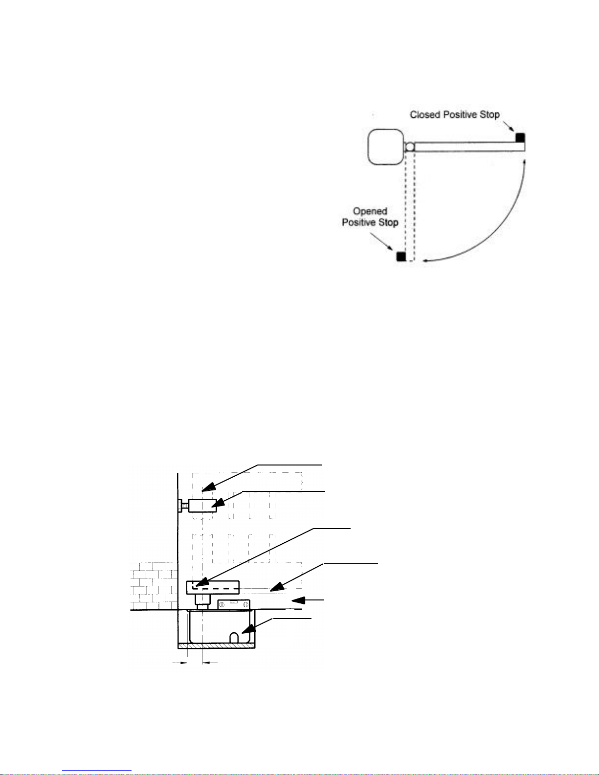
3. Make sure the gate leaf has positive stops in
both the opening and closing directions (see
Figure 5).
Figure 5. Positive stops are required in the
fully opened and fully closed gate positions
4. You need to determine a means of attaching the
splined collar to the gate. If the gate leaf is steel, you
may be able to weld the collar directly to the gate. If
the bottom of the gate is more than 2 1/8 in. above
grade level you will have to extend the collar with pipe
or round stock. If your gate is aluminum or wood, you
will have to weld the collar to a steel plate or shoe that
can be bolted to the bottom of the gate.
760 Operator is inside of the mounting box.
The mounting box is 6 1/4 in. deep.
Absolute minimum of 1 3/8 in. between the
axis of rotation and the gate post
Figure 4. Constraints on the geometry of the gate leaf
(Single hinge installation shown)
9
Axis of rotation for the
gate leaf must be plumb
Upper hinge on
the gate leaf
90-deg corner
on the gate leaf
This vertical dimension is
equal to the thickness of
the gate leaf shoe
2 1/8 in. between shoe and finished grade
Page 10
Note: If you are installing the 760 Operator with
an extension arm, some of the constraints do not
apply to your gate leaf. See the section
"Installing an Extension Arm" for more
information (page 25).
Installing the 760 Operator
Installing the 760 Operator consists of the following
steps:
Manual Release
Note: The 760 CBAC provides a Manual Release
for manually operating the gate. Although the
760 SB and the 760 SBS come with this release
mechanism, it is not necessary to use this feature
to release the gate. The SB and SBS have no
internal locking and can be pushed manually at
any time.
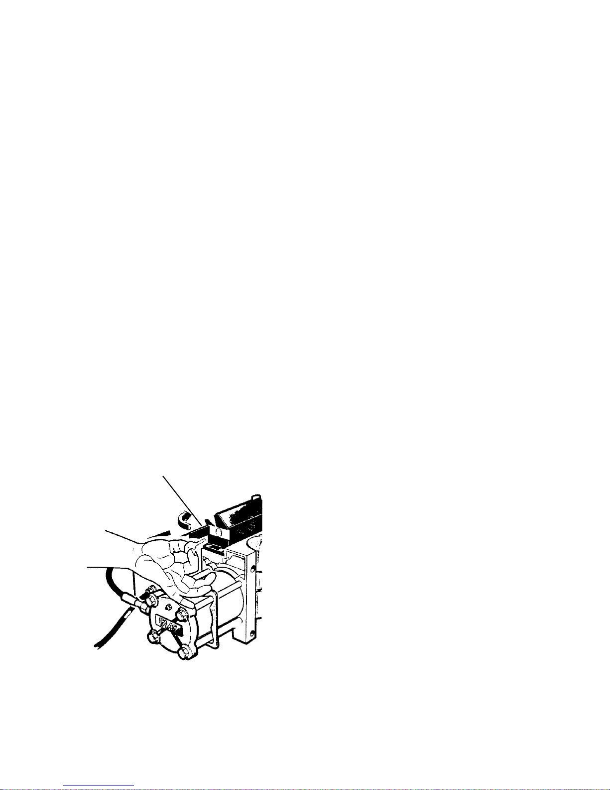
The Manual Release mechanism on the Standard
models is a built-in release device of the 760 Operator
(see Figure 6). This device is accessible from both
sides of the gate. You disengage the hydraulic
operation of the operator by opening the access door
(there is one on either side of the manual release
housing), inserting the triangular key, and turning the
key toward the gate post one full turn. Then you can
move the gate by hand to open or close the gate.
Operating the gate by hand is necessary during
installation and is useful during power failures.
To re-engage the hydraulic operation of the gate, turn
the key away from the gate post until resistance is met.
Open the access door
1.
to the release device
• Install the load bearing box, electrical
conduit, and drain pipe
• Secure the load bearing box
• Install the gate leaf shoe
• Install the gate leaf
• Install the operator in the load bearing box
• Install the control panel
• Adjust the hydraulic pressures for the
operator
• Check the motor rotation
• Fine-tune the bypass valve pressures
Install the Load Bearing Box
You need to excavate a cavity for the load bearing box
of the 760 Operator according to the dimensions
shown in Figures 4 and 7. (Your soil conditions will
also determine the size of the cavity.) Accurately
positioning the splined shaft of the pinion (inside the
mounting box) beneath the gate hinge is critical.
Proper alignment will ensure a full swing without
binding.
Note: You need to insure that the load bearing box is
well drained by means of pipes, gravel drainage, or
both, whatever is appropriate for your soil conditions.
Use one of the access holes in the load bearing box for
the drainage pipe leaving the box.
2. Insert the key and turn
it one full turn toward the
gate post for release.
Figure 6. The Manual Release in the
760 Standard Operator
Install your electrical conduit through another hole in
the load bearing box. Use conduit of sufficient size
and quality to accommodate the high-voltage wiring
that must run between the operator (in the load bearing
box) and the control panel.
Caution: Be sure to conform to all applicable
electrical codes.
10
Page 11
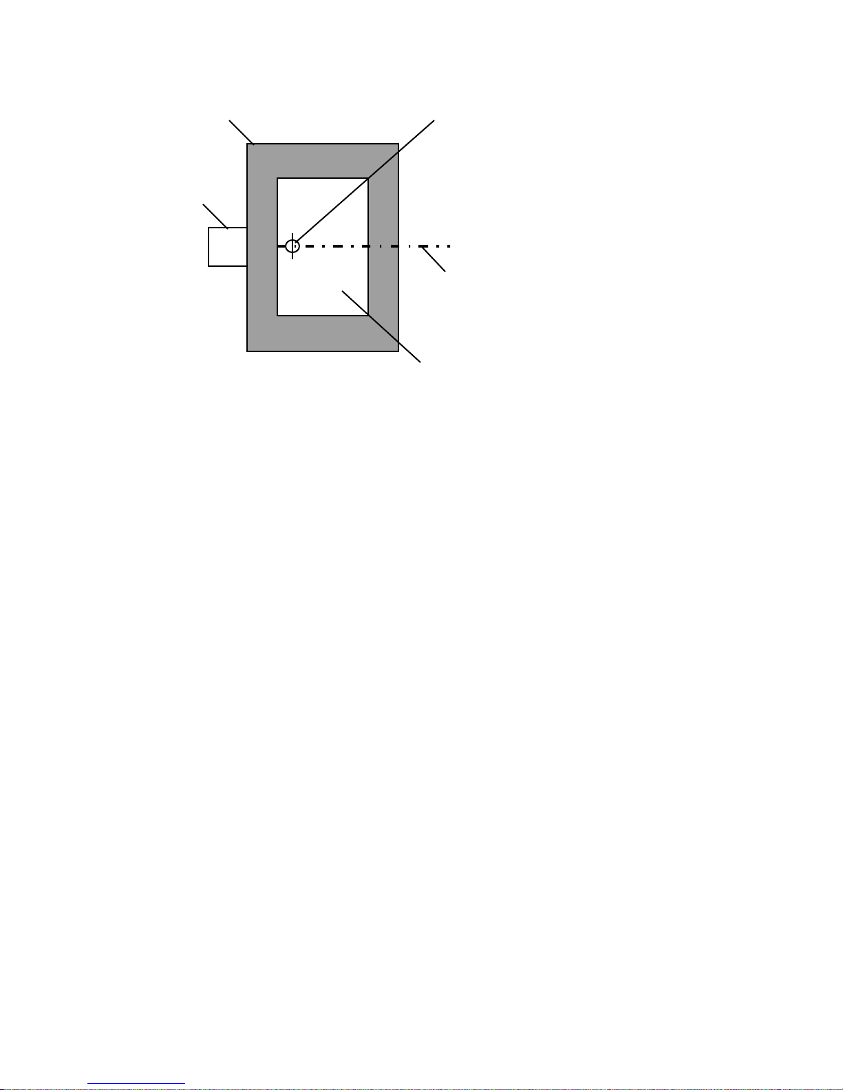
Cement surrounding the
mounting box or cement footing
to which box is attached
Gate post
Axis of rotation
of gate leaf
Centerline of
gate leaf
Mounting box:
10 1/4 x 19 1/4 in.
(26 x 49 cm)
Figure 7. The orientation of the load bearing box and concrete when you
secure the load bearing box
You next need to test fit the load bearing box in the
cavity. The fit must meet the following requirements:
1. The center of the splined shaft of the pinion
must align perfectly with the axis of rotation for
the gate leaf. Use a plumb line to insure this
vertical alignment.
2. The cover of the load bearing box should be
even with the finished grade beneath the gate,
but more importantly, the top edges of the load
bearing box must be level. Use a level to insure
this horizontal alignment.
Secure the Load Bearing Box
Next you need to fix the mounting box in place if it
meets all the requirements for alignment. Precisely how
you fix the box in place will vary according to your soil
conditions and your installation site.
Example: For example, you might surround the exterior
of the mounting box with enough soil to extend 1/2 way
up the boxso that soil covers the access holes for the
electrical conduit and drainage pipe. While such soil
should be firmly packed around the box, you have to be
sure that in packing the soil you do not misalign the
center of the splined shaft of the pinion or the top edge
of the box. In fact, you should recheck all alignments
and adjust the mounting box if necessary. Then you can
pour concrete around the box and up to its top edge so
as to be level with the finished grade beneath the gate
leaf.
Example: As another example, you might use a
foundation plate set in a cement footing. Then you could
bolt the mounting box to the plate, taking care that your
bolts do not interfere with the 760 Operator yet to be
installed in the box. This method requires you to
compensate for the unevenness of the bottom of the
mounting box.
Note: No matter what your method of fixing the
mounting box in place, use sufficient concrete to hold
the mounting box in place when it is under the stresses
inherent in hydraulically swinging the gate.
No matter how you secure the mounting box, if you use
poured concrete, allow a minimum of two full days
before you install the 760 Operator inside the mounting
box.
Install the Gate Leaf Shoe
Note: Building a gate leaf shoe is not absolutely
necessary. It is a method that will work in most
applications. However, if you wish to weld the splined
collar directly to the gate or attach it by some other
means, feel free to do so.
Caution: Do not install the gate leaf shoe, even for test
fitting, until any concrete beneath or around the
mounting box has had a chance to set for a minimum of
two full days.
If the vertical distance between the finished grade under
the gate and the bottom of the gate leaf is more than
2 3/8 in. (see Figure 4), you need to do one of the
following:
11
Page 12
• Install a length of appropriately sized pipe
between the splined collar of the operator and
the gate leaf shoe.
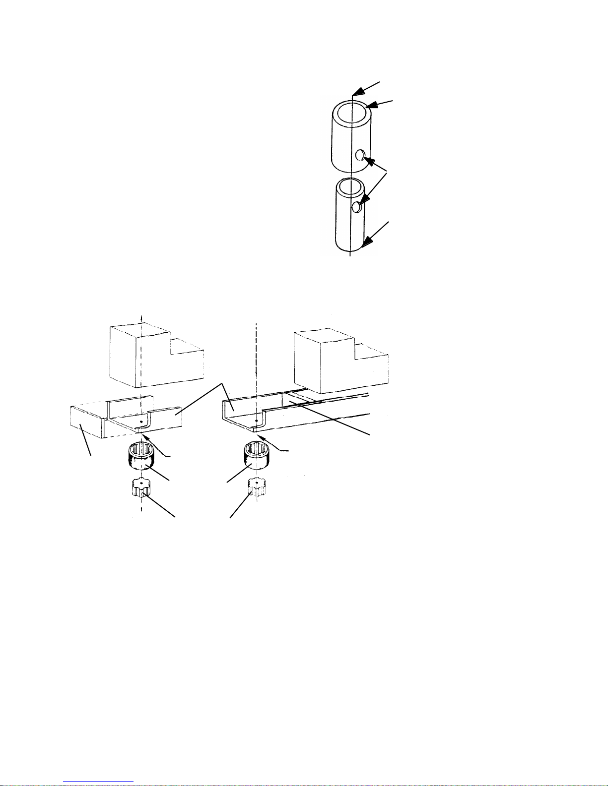
• Construct a shear-pin assembly to
accommodate the extra vertical distance. The
assembly is welded to the bottom of the gate or
gate leaf shoe on one end and to the sleeve for
the splined collar on the other end (see Figures
8 and 9). Such an assembly requires a gate with
two hinges and also protects the pinion and
splined shaft in the event something hits the
gate with great force.
Installing the gate leaf shoe involves making the gate
leaf shoe, positioning it, and welding it to the splined
collar.
The gate leaf shoe is designed to carry the weight of the
gate leaf and transfer the weight to the splined shaft of
the pinion.
U-shaped
Gate leaf
section of
gate leaf
shoe
Axis of rotation of the gate leaf
Weld this end of this pipe to
the bottom of the gate leaf
shoe, being certain you have
aligned the axes of rotation.
This 2 in. pipe (schedule 160)
has an inside diameter of 1.689 in.
Bolt or shear pin goes
through these holes and
the holes on the opposite
sides of the pipes.
Weld this end of this pipe to the
sleeve for the splined shaft (do not
weld anything to the splined shaft
itself). This 1 1/4 in. pipe (schedule
160) has an outside diameter of
1.660 in.
Figure 8. A sample shear-pin assembly
Gate leaf
Vertical
section
Vertical
section
Axis of rotation
within body of
gate leaf
Splined shaft
sleeve
Splined shaft
Axis of rotation
outside body of
gate leaf
Note: The gate's axis of rotation may fall within or outside the body of the gate leaf.
Figure 9. Parts of the gate leaf shoe
The shoe is made of a U-shaped section and a vertical
section (see Figure 9). Later you will weld the bottom of
the U-shaped section to the sleeve for the splined shaft
(or to the shear-pin assembly, which is welded to the
splined collar).
Construct the U-shaped section of the shoe and verify
that it fits around the gate leaf. Position the U-shaped
section over the splined shaft so that the leaf's axis of
Since the gate leaf shoe holds the gate leaf, both
sections must be made of steel at least 1/4 in.
rotation will fall within the minimum dimensions shown
in Figure 10.
(0.6 cm) thick. The U-shaped section of the shoe must
be a minimum of 5 3/4 in. (2.1 cm) long and must be as
wide as the gate leaf is thick and must fit as tightly as
possible to minimize leaf movement within the shoe
On the U-shaped section of the shoe, mark the position
for the leaf's axis of rotation. Next, drill a pilot hole in
the U-shaped section to mark the axis of rotation point
(see Figure 10).
12
Page 13
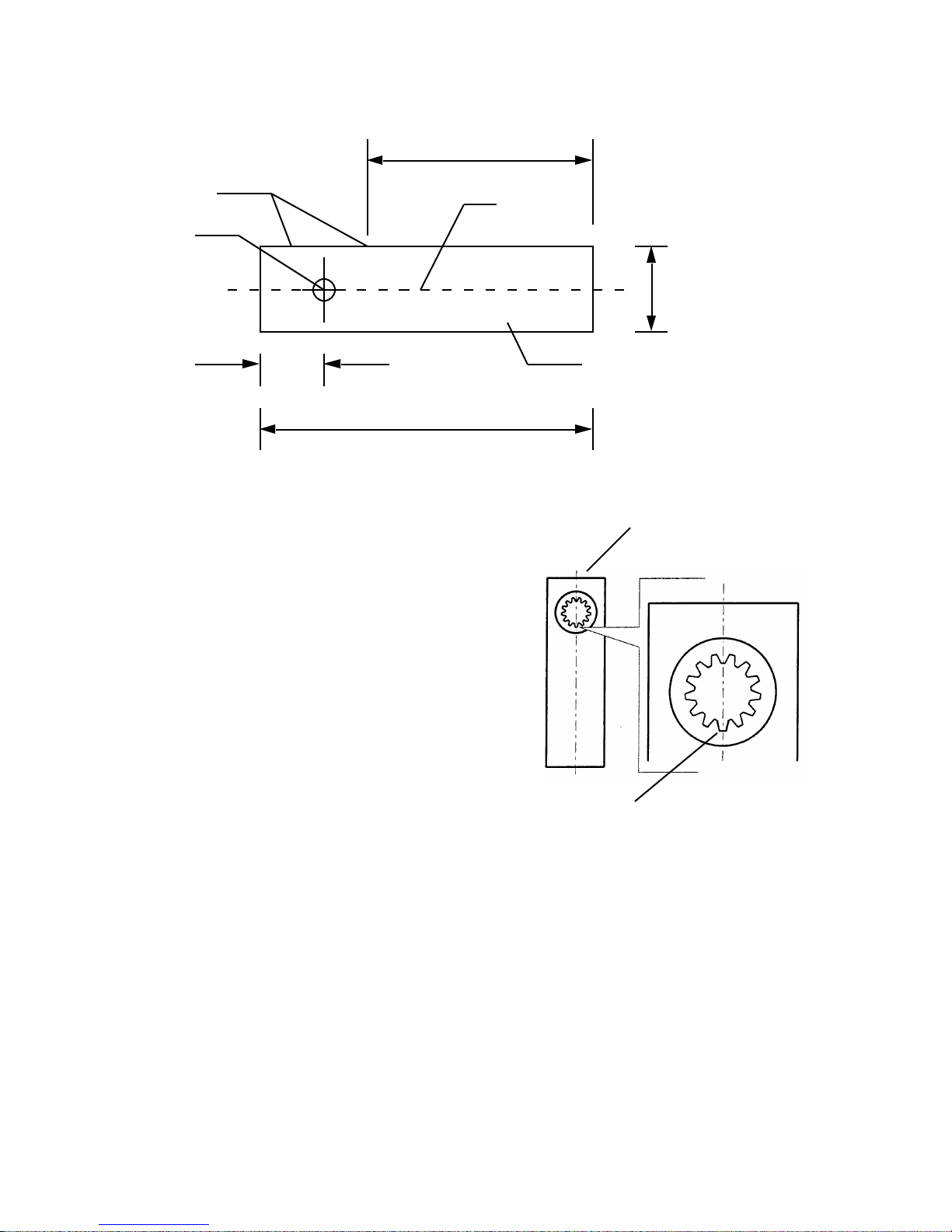
and mark the position for the placement of the vertical section of the shoe.
3/4 in. (1.9 cm)
Bottom of
U-shaped
section
Absolute minimum of 5 in. (12.7 cm)
between vertical section and end of
U-shaped section
Vertical section can be
located on either side
of axis of rotation
Axis of rotation
for gate leaf
Minimum of
Recommended minimum of 10 in. (25 cm)
Centerline of
gate leaf
Figure 10. Top view of the U-shaped section of the gate leaf shoe
thehinge(s), the pilot hole, and the center of the splined
Next you need to position the splined collar (or the
shaft.
shear-pin assembly) on the bottom side of the U-shaped
section of the shoe as shown in Figure 9. In positioning
the splined collar, meet the following two requirements:
Thickness
of the
gate leaf
Gate post end of the gate leaf shoe
1. On the bottom of the U-shaped shoe section,
accurately center the sleeve around the pilot
hole that marks the axis of rotation. Accuracy
is important.
2. Center one notch on the sleeve along the
centerline of the gate leaf (see Figure 11). You
can then align this centered notch with the
punch mark on the splined shaft of the pinion
as a reference in case you ever need to remove
the shoe later.
Caution: NEVER weld the splined shaft of the pinion
to anything.
Spot-weld the splined collar into place on the bottom of
the shoe's U-shaped section. If you are using the shearpin assembly, spot weld the splined collar to the bottom
of the shear-pin assembly, and spot weld the top of the
shear-pin assembly to the bottom of the shoe’s Ushaped section. (You must still meet the two alignment
requirements noted above even if you are using the
shear-pin assembly.)
Next you must test the temporarily welded position of
the sleeve. Fit the sleeve over the splined shaft with the
U-shaped section aligned in the gate leaf's fully closed
position. Verify that the axis of rotation falls through
Align one notch on the sleeve
of the splined shaft with the punch
mark on the splined shaft itself
Figure 11. Center one notch along the
centerline of the gate leaf shoe and place over
the punch mark on the splined shaft
If the axis of rotation alignments are correct, then
permanently weld the sleeve for the splined shaft to the
bottom of the U-shaped section of the shoe.
Also, you now need to weld the pilot hole closed, and
you need to weld the vertical section of the shoe to the
U-shaped section of the shoe.
Lubricate the splined shaft with grease and place the
finished gate leaf shoe assembly over the shaft in the
closed position.
13
Page 14
Install the Gate Leaf
If you are not using the telescoping shear-pin assembly,
install the gate leaf by placing its 90-deg corner into the
gate leaf shoe and then installing the other gate hinge(s).
Next, very slowly open and close the gate leaf a few
times to see if it moves smoothly and evenly through its
entire path.
Install the Operator in
the Load Bearing Box
Note: The installation of the operator assumes you have
installed the load bearing box and the gate leaf. Do not
proceed with installing the operator until the load
bearing box and gate leaf have been installed.
Remove Covers
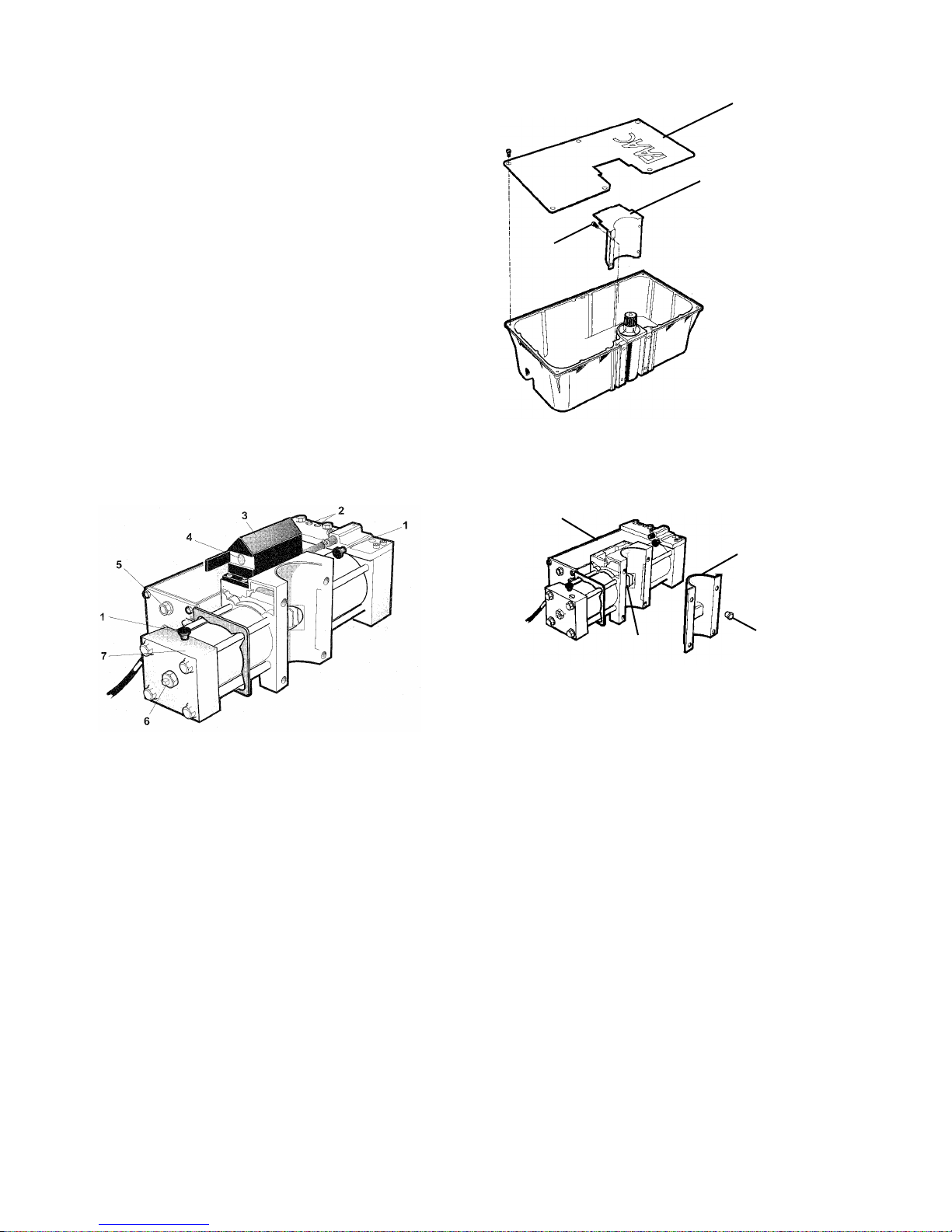
To install the 760 Operator (see Figure 12), first prepare
the splined shaft in the mounting box by removing the
pinion cover (Figure 13). To remove the pinion cover,
remove the four bolts holding the cover.
Mounting box
cover
Pinion cover
Bolt,
1 of 4
Figure 13. Remove the pinion cover by
removing the snap-on bolts that hold it to the
pinion assembly
Ram unit
Rack cover
1 Bleed screw
2 Bypass valves
3 Manual Release
4 Release lock (optional)
5 Oil plug
6 Adjustment screw for the beginning of the braking phase
7 Deceleration adjustment screw
Figure 12. The parts of the 760 Operator with
soft stop
Next, remove the plugs holding the rack cover to the
760 Operator (see Figure 14). Be sure to keep track of
the plugs and the rack and pinion covers in case you
ever need to remove the operator for repair.
Rack
Plug,
1 of 2
Figure 14. Remove the rack cover by
removing the plugs that hold it on the
760 Operator
Position the Gate Leaf
The 760 Operator is shipped to you with the hydraulic
ram in the half-opened position. This means that before
you mate the pinion and the rack, you need to open your
gate leaf to the half opened position to assure the
maximum travel for your gate leaf in the opening and
closing directions.
The greater the arc of swing in your gate leaf (the closer
you are to the maximum swing of 148 degrees), the
more important it is that you be exact in opening the
gate to the half-opened position. If necessary, measure
the distance.
If your gate leaf opens less than 90 deg, you can have 10
deg of braking in only one direction (call us for details).
To assure any braking whatsoever, you must compute
the opening distance for your gate leaf to use before you
mate the rack and pinion. For braking on closing,
determine what 3/4 the length of your gate leaf is, and
14
Page 15
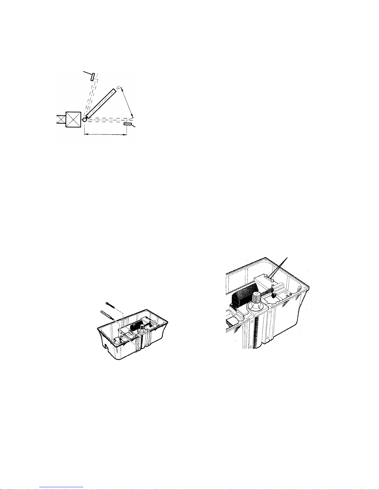
open the gate leaf that distance from the closed position
(see Figure 15).
Adjust the Pressures
for the Operator(s)
Fully opened
limit stop
3/4 the length of
the gate leaf
Fully closed
Length of the
limit stop
gate leaf
Figure 15. On a gate leaf that opens less than
90 deg, properly position the gate leaf before
installing the 760 Operator
Mount the Operator
Once the gate leaf is in the proper partially opened
position, install two lock washers and the two
extraordinary, long-headed bolts through the two holes
in the bottom of the 760 Operator (see Figure 16). Mate
the rack in the operator to the pinion in the mounting
box. Next, insert the two bolts through the top of the
operator and into the mounting box (see Figure 16).
Tighten all four bolts securely.
WARNING! You must decrease the pressures of the
gate’s opening and closing momentum completely
before you operate the gate electrically. The pressure
valves are not preset at the factory and may operate the
gate leaf with enough force to endanger people and
seriously damage the gate leaf itself.
The green and red screws on the top of the oil reservoir
of the 760 Operator are the bypass valve adjustments
that control the force of the gate leaf’s opening and
closing momentum (see Figure 17). For either valve,
turning the screw clockwise increases the pressure and
turning it counterclockwise decreases the pressure.
Which screw controls the opening thrust of the gate and
which the closing thrust depends on the orientation of
the unit in your installation site. The green screw always
controls the clockwise rotation of the splined shaft, and
the red screw always controls the counterclockwise
rotation of the splined shaft.
Before you operate the gate for the first time, you must
completely decrease the pressures for both opening and
closing. Turn both screws counter-clockwise all the
way. Later you will adjust these pressures.
Bypass valve
adjustment screws
Install the ordinary
bolts through the
top of the operator
Install the long,
extraordinary
bolts through
the bottom of
the operator
Figure 16. Anchor the operator to the mounting
box and pinion assembly
Figure 17. Decrease the pressures controlled
by the bypass valve screws completely before
you operate the gate electrically
15
Page 16
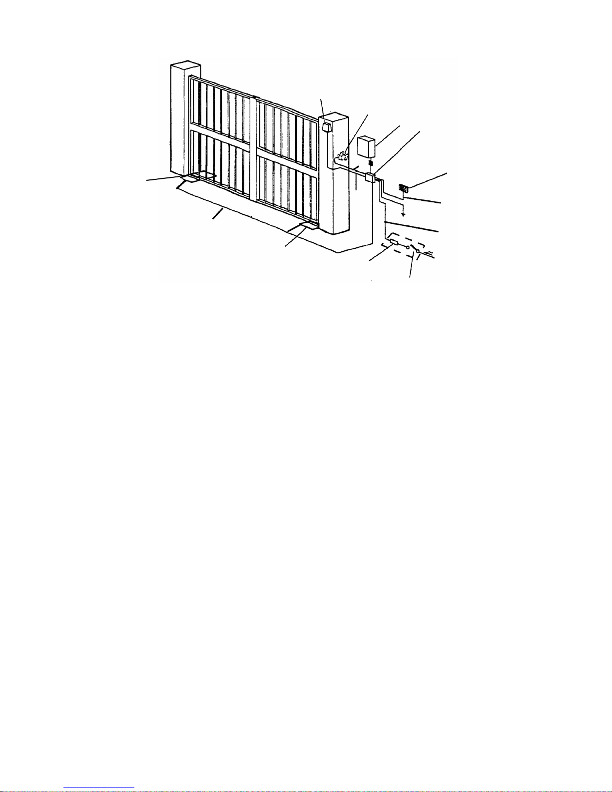
8
7
2
5
1
A
Locate switches 10 ft from gate
Gate System Parts
1 760 Operator in mounting box 220 VAC
2 760 Control Panel box A 4 X 14 AWG
3 Main power switch B 3 X 18 AWG
4 Circuit breaker C 5 X 18 AWG
5 Main junction box D 5 X 18 AWG
6 Switch for 760 Operator E 4 X 14 AWG up
7 Switch for 760 Operator to 414 ft (126 m)
8 Radio receiver
Figure 18. Typical layout of gate system with 760 Operators
Install the 450 MPS
Control Panel
Locate the control panel in a convenient position,
considering the movement of the gate. Figure 7 shows
a basic layout for a two-leaf gate with two 760
Operators.
Installing the control panel consists of the following
general steps:
• Connect the main power supply
• Connect the operator(s) to the control panel
• Check the direction of the motor’s rotation
• Connect other devices
• Set operating controls
The installer is responsible for grounding the operator
systems, for providing the main power breaker switch,
and for making sure that the entire gate system meets
all applicable electrical codes.
Follow the instructions that follow to install the 450
MPS control panel for the 760 Operator.
C
B
6
D
E
1
4
3
Wire Gauges for Given
Power Source Voltage
Connect the Main Power Supply
WARNING! Turn the main power off before you
make any electrical connections or set any switches
inside the control panel box.
Wire the main power supply to control panel terminals
in block J1 (see Figures 20 and 21). The installer is
responsible for insuring that a separate, grounded
circuit protected by a circuit breaker is between the
control panel and the main power supply. All wiring
should conform to applicable electrical codes, and all
wiring and fittings should be weatherproof and/or
suitable for burial.
Connect the ground to the grounding terminal in block
J1 and connect the power wires to the terminals
labeled N (neutral) and L (line).
Caution: The operators are grounded only by the
grounded circuit the installer provides.
Note: For a 230v system, a neutral is not needed.
Connect one 115v line to the L (line terminal) and a
second 115v line to the N (neutral terminal).
16
Page 17
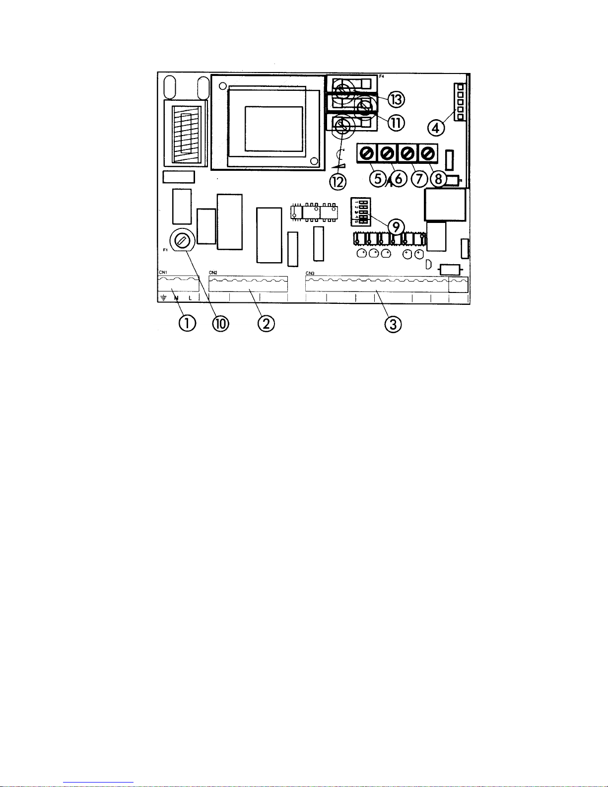
1 J1 terminal block for main power supply 8 Leaf delay potentiometer
2 J2 terminal block for connecting the operator(s) 9 DIP switch assembly
3 J3 terminal block for low-voltage accessories Fuses 220 VAC 115 VAC
4 J4 quick connector port 10 F1, Main power 5 A 10 A
5 Pressure adjustment potentiometer 11 F2, Accessories 800 mA 800 mA
6 Pause time potentiometer 12 F3, Electric lock 1.6 A 1.6 A
7 Potentiometer for adjusting open/close time 13 F4, Microprocessor 250 mA 250 mA
Figure 19. The 450 MPS control panel
Connect the Operator(s) to
the Control Panel
WARNING! Turn the main power off before you make
any electrical connections or set any switches inside the
control panel box.
Using a Junction Box
Connecting your operator(s) to the control panel may
require the use of one or more junction boxes. Whether
you need 0, 1, or 2 U.L. Listed junction boxes depends
on your gate design.
If any operator is more than 2 ft away from the U.L.
Listed control panel enclosure, the connection must be
made inside a junction box. Use a U. L. Listed cord grip
where the operator cord enters the junction box; use
conduit between the junction box and the enclosure.
Caution: The control panel will not operate without an
operator connected to terminals 3, 4, and 5.
If your gate system has one operator, connect the
capacitor and the red and black (or brown and black)
wires from your operator to the terminals 3 and 5 in
block J2. Connect the white (or blue) wire from the
operator to terminal 4.
Note: If you want to delay the closing of one gate
leaf in a two-leaf gate design, be sure to connect
its operator to Motor 1 (terminals 3, 4, and 5).
If your gate system has two operators, connect the
second operator to terminals 6, 7, and 8 in block J2.
Connect the second capacitor and the red and black (or
brown and black) wires to terminals 6 and 8, and
connect the white (or blue) wire from the operator to
terminal 7.
17
Page 18
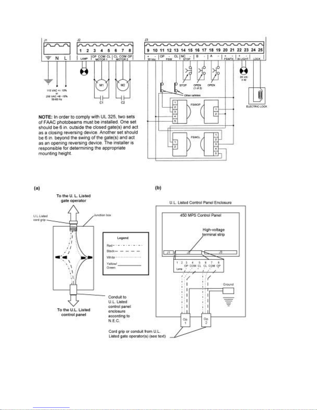
Figure 20. The terminal strip wiring of the 450 MPS with photobeams
Figure 21. Wiring detail (a) inside the junction box and (b) from the junction box or operator
to the high-voltage terminal strip on the 450 MPS control panel
18
Page 19

Check the Motor’s
Direction of Rotation
After you have connected the main power supply, the
capacitor(s), and the operator(s) to the control panel,
you need to check the direction of rotation for each
operator motor in your gate design.
To check a motor’s direction of rotation, you must have
three closed circuits on terminal block J3. Install one
circuit between terminals 11 and 21, another circuit
between 13 and 21, and another circuit (or stop device)
between terminal 14 and 15.
You cannot check the motor’s direction of rotation
without these circuits (jumpers) or the accessories.
When properly prepared for testing, the LEDs DL3,
DL4, and DL5 should be illuminated.
WARNING! Running the operator—even for testing
purposes—without a connected reversing device is
potentially dangerous. Do not place yourself within the
path of the moving gate during your test.
You also need to install a normally open activation
device across terminals 18 and 19.
Disengage the operator(s) with the Manual Release key,
and open the gate by hand about halfway (See Figure 3).
Next, engage the operator(s) with the Manual Release
key so that you can check the rotation of the motor(s).
Turn on the main power and send an activating signal to
the operator(s). The gate leaf (or leaves) should open. If
a gate leaf closes, then you need to turn off the main
power and reverse the connection of the red and black
(or brown and black) wires on terminal block J2 for the
operator controlling that leaf. Then you need to recheck
the rotation direction again.
If your gate system has two operators, be sure the motor
of each rotates in the correct direction.
After having completed your test of the motor’s
direction of rotation, replace any test circuits you
installed (between terminals 11 and 21, between 13 and
21, and between 14 and 15) with the proper reversing
and stop devices. The instructions for installing such
accessories follow.
Connect Other Devices
WARNING! Turn the main power off before you make
any electrical connections or set any switches inside the
control panel box.
Now you can connect additional reversing and activat-
ing devices to the control panel. Refer to Figure 19 for
the general control panel layout, and refer to Figure 20
for the layout of the terminal strip.
Power Supply for Accessories: You can access a 30
VDC output for supplying power to accessories that
require DC voltage through terminals 9 and 10 (located
above the label 30 Vcc) on terminal block J3. In most
cases, this source can be used to power 24 VDC
accessories.
Note: The 450 MPS control panel allows a maximum
accessory load of 800 mA.
Reversing Devices: Reversing devices include
photobeams, inductive loops, and so forth. All of the
reversing devices should have contacts of the normally
closed (N.C.) type. Where you connect a device depends
on whether you want the device to operate during
opening or during closing.
Note: UL does not recognize the FAAC system with
loop detectors or safety edges. FAAC photobeams must
be used to comply with UL 325.
Caution: Failure of a reversing device that operates
during opening, causes a gate to lock in the closed
position and requires the use of the Manual Release key.
To wire photobeams, refer to Figure 9 (see FSWOP for
opening photobeams, and FSWCL for closing
photocells—connect the photobeams exactly as shown).
See Figure 22 for the wiring of a variety of common
accessories. In either case, if you have multiple devices,
wire them in series.
Activating Devices: The activating devices for your
gate must have normally open (N.O.) contacts. Connect
all devices to terminals 18 and 19. If you have a dual
gate and want a particular activating device to open only
one leaf, connect it to terminals 16 and 17.
Decoder Card: If you are installing a FAAC radio
receiver, a Digicard magnetic card reader, or a Digikey
keypad, use the quick-fit connector J4 for the radio
receiver or the DS (formerly the MD01) decoder card
(see Figure 19).
19
Page 20
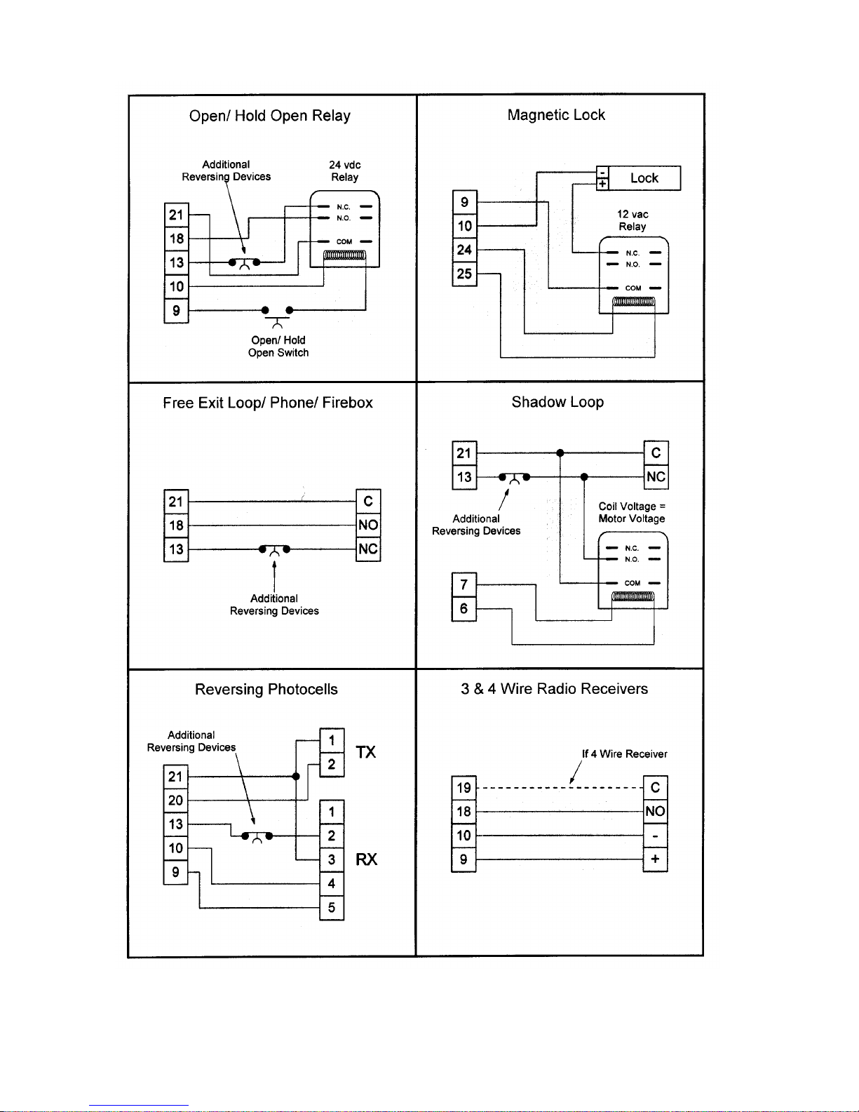
Figure 22. Common accessories wired to 450 MPS.
20
Page 21

Note: If you are using both a receiver and a
decoder, hard wire the decoder and plug the
receiver in.
Open/Hold Open Device: To open and hold open the
gate, an Open/Hold Open device must make a set of
contacts across terminals 18 and 21 and must break a set
of contacts between terminals 13 and 21. See Figure 22
for more detail.
Stop Button: The stop button you install must have
normally closed (N.C.) contacts. Multiple stop buttons
must be wired in series. Connect your stop device
between terminals 14 and 15.
The LED Indicators: The five light-emitting diodes
(LEDs) on the control panel can be used to check for the
proper functioning of the devices you attach to the
control panel. The LED lights are on whenever the
contacts are closed across each of the respective
terminals.
See Figure 22 for the wiring of a magnetic locking
device.
Warning Light: Connect a warning light to terminals
22 and 23 in the group labeled W.LIGHT in terminal
block J3. The terminals provide an output voltage of 30
VDC, maximum power 3 Watts. This output voltage
will power most 24 VDC warning lights.
Note: The behavior of the warning light varies
according to the logic you have set.
Logics A, S, E, EP, and B: The warning light is
on steadily during opening and the pause phase.
During closing, the light flashes.
Logic C: The warning light is on steadily during
opening and flashes during closing.
Set Operating Controls
DL1 and DL2 should illuminate only when an activating
signal is sent for 2 and 1 gate leaves, respectively. DL3
should be illuminated except when the stop button is
pressed. DL4 and DL5 should be illuminated except
when the reversing devices for opening and closing,
respectively, are triggered. Use the LEDs and the table
below to determine if the accessory devices you have
installed are operating properly.
LED On Off
DL1,
Open 2 leaves
DL2,
Open 1 leaf
DL3, Stop Command not
DL4,
FTSW Open
DL5,
FTSW Close
Electric Lock: Connect your lock to the terminals 24
and 25. The terminals provide 12 VAC that pulses for 4
seconds whenever the gate starts to open. An electric
lock can make use of the reversing stroke function
controlled by DIP switch 5. A reversing stroke is a short
closing phase that allows the electric lock time to
disengage itself before the operator starts its opening.
Turn DIP switch 5 on only if necessary for your lock to
function correctly.
Command
active
Command
active
active
Opening
reversing
devices not
triggered
Closing
reversing
devices not
triggered
Command
inactive
Command
inactive
Command
active
Opening
reversing
device triggered
Closing
reversing
device triggered
WARNING! Turn off the main power before you make
any electrical connections or set any switches inside the
control panel box.
You need to set DIP switches and adjust the
potentiometers on the control panel for your gate's
operation. The 450 MPS Control Panel has 5 DIP
switches and 4 potentiometers that control a wide range
of functions.
Set DIP Switches
Switches 1, 2, and 3 (Operating Logic): The 450 MPS
Control Panel offers six operating modes: A, S, E, EP,
B, and C.
Refer to the operating logic tables earlier in these
instructions for more detail about the logical modes
available on the 450 MPS control panel.
Switches 1, 2, and 3 control the operating logic
according to the following table:
Switch
Logic
A on off on
S on off off
E off on off
EP on on off
B on on on
C off off on
Switch 4 (Reversing Device Behavior on Closing):
Refer to the operating logic tables earlier in this manual
and to the chart below for how to set DIP switch 4.
1 2 3
21
Page 22

Gate Behavior
During Closing
Gate immediately
reverses its direction
when a reversing device
is triggered
Gate stops and reverse its
direction when reversing
device is no longer
triggered
Switch 5 (Reversing Stroke): Sometimes electric locks
require a reversing stroke to disengage the lock. If your
gate does not always open because your lock is hanging
up, you may want to activate the reversing stroke.
Reversing Stroke Switch 5
Not activated off
Activated on
Switch 4
off
on
Adjust the Potentiometers
The four potentiometers control the torque, the pause
time, the opening/closing time of operation, and the leaf
delay for closing.
Torque: The torque potentiometer on the 450 MPS
must be turned all the way clockwise for the 760
Operator. The potentiometer controls voltage to the
operator. It is used for the FAAC model 412, a screw
drive operator. The torque potentiometer cannot be
used to adjust the operator’s hydraulic operating
pressures.
Caution: Failure to turn the torque potentiometer to
maximum in the clockwise direction jeopardizes the life
of the motor of your operator.
WARNING! Adjust the operating pressure on the 400
Operator only by means of the hydraulic bypass valve
screws. See pages 15 and 22.
Pause Time: The pause (time gate stays open) can be
adjusted from 0 to 240 seconds. Turn the potentiometer
clockwise to increase the pause time and
counterclockwise to decrease the pause time.
For optimal operation, set the time so that the motor
remains active for a couple of seconds after the leaf has
reached its positive stop for opening and for closing.
Leaf Delay: You may choose to delay one leaf on
closing for overlapping gate leaves. Be sure the operator
on the leaf for delayed closing is connected to Motor 1.
On opening, the leaf connected to Motor 2 is delayed
2.5 sec.
Note: You cannot adjust this opening delay of the
operator connected to Motor 2. However, you can turn
off the delay by closing the jumper labeled “Open Leaf
Delay Disable” on the 450 MPS.
The closing leaf-delay time is adjustable from 0 to 28
seconds. Turn the potentiometer clockwise to increase
the time and counterclockwise to decrease the time.
Note: In one-leaf gate designs, be sure to set the
potentiometer for leaf delay to its minimum (0 seconds).
Note: If the opening/closing time is set at less than the
leaf delay time, the delayed leaf closes at the end of the
closing time.
Fine-tune the Bypass
Valve Pressures
The pressure a gate leaf applies to an obstacle in its path
is determined by the bypass valve adjustment. The
safety standards of FAAC International, Inc.,
recommend that the gate should stop when it meets with
a force of more than 33 lb (15 kg).
WARNING! The pressure valves may operate the gate
leaf with enough force to endanger people and seriously
damage the gate leaf itself. Increase the pressures in
small increments (1/4 turn), and set the pressure
adjustments at the minimum level necessary for the
gate's operation.
Which bypass valve screw controls the opening thrust of
the gate and which the closing thrust depends on the
orientation of the unit in your installation site. The green
screw always controls the clockwise rotation of the
splined shaft, and the red screw always controls the
counterclockwise rotation of the splined shaft.
Opening/Closing Time: The opening/closing time is
adjustable from 10 to 62 seconds. The approximate
opening/closing time for a 90-degree opening varies
from 12 to 17 seconds, depending on the model. Turn
the potentiometer clockwise to increase the time and
counterclockwise to decrease the time.
Fine tune the pressures for both opening and closing
after you have installed the control panel for the 760
Operator. Set the pressures at the minimum necessary to
open or close the gate leaf.
Note: The red and green screws are not a speed
adjustment. The motor speed and pump displacement
are constant.
22
Page 23
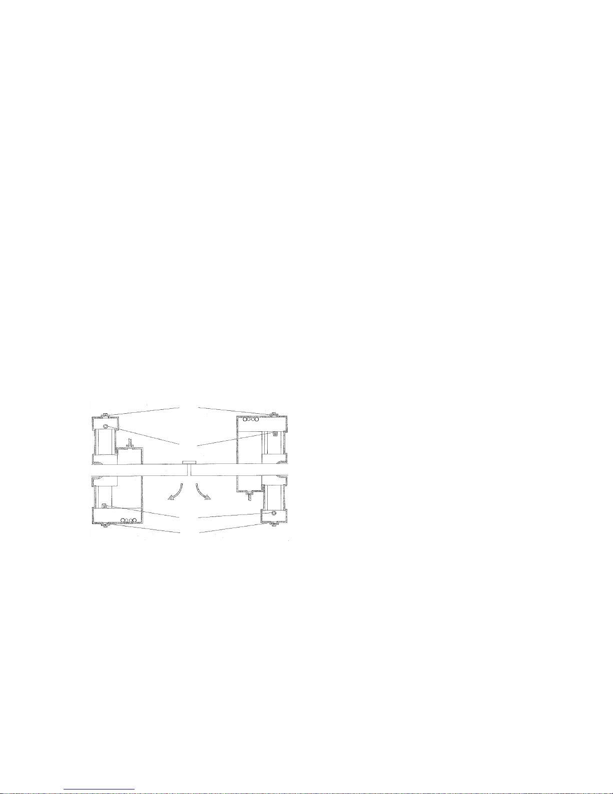
Warning! Do not increase the pressure adjustments
A
D
C
B
excessively in an attempt to speed up the gate. Doing so
can increase the risk of serious injury.
Adjust the Beginning of
the Braking Phase
You need to adjust the start of the braking phase for
opening and closing. You adjust the braking to no more
than 10 deg before fully closed and fully opened. Figure
23 shows the location of the adjustment screws for the
beginning of the braking phase.
Note: The 760 Operator ships from the factory with the
braking phase adjustment screws turned all the way
clock-wise. This position of the screws corresponds to
no braking phase whatsoever.
If you have a CBAC model with hydraulic locking, you
first need to use the Manual Release to disengage
hydraulic operation of the 760 Operator before you
adjust the screws for defining the beginning of the
braking phase.
turn the bolt one half of a turn clockwise and retighten
the brass lock nut.
Manually move the gate leaf to the fully opened position
against the opened limit stop. Loosen the brass lock nut
for the opening brake adjustment bolt. Next, turn the
square-headed opening brake adjustment bolt
counterclockwise until the gate leaf starts moving. Then
turn the bolt one half of a turn clockwise and retighten
the lock nut.
Note: If your gate leaf opens less than 90 deg, setting
the beginning of the braking phase may have no effect
on the gate leaf. The only way to adjust the beginning of
the braking phase is with the position of the gate leaf
and the rack when you mate the rack and pinion. Call us
for details.
Note: If you wish the braking of the operator in the
opening or closing direction to start at less then 10 deg,
turn the corresponding bolt another couple of turns.
There is no way to begin braking at more than 10 deg.
To adjust the start of the braking phase, first make sure
the deceleration adjustment screws are not tightened
completely. Unscrew them at least a couple of turns (see
Figure 24).
A Brake adjustment bolt for closing
B Brake adjustment bolt for opening
C Opening bleed screw on CR models
D Closing bleed screw on CR models
Figure 23. The location of the brake
adjustment bolts for the beginning of the
braking phase and the bleed screws.
Adjust the Braking Intensity
Figure 12 shows you the location of one of the
deceleration adjustment screws; the other is similarly
located on the other end of the operator. Figure 24
shows that you turn the adjustment screws clockwise to
increase the intensity of the braking and
counterclockwise to reduce the intensity of the braking.
Assemble and Install
the Manual Release
The parts for the Manual Release are shipped in the
shrink-wrapped package with other small parts.
To assemble the Manual Release, lay open the black
plastic Manual Release housing so that the FAAC logo
faces downward. You need to place in the ribbing on
one side of the black plastic the brass gear assembly and
the plastic gear assembly. The gears themselves for both
parts sit within the middle of the housing and engage
one another (see Figure 25).
Then you can gently fold the black plastic housing
around the gear assemblies. The black plastic housing
should snap shut if you have the access doors to the key
holes out of the way.
Then, place the gate leaf in the fully closed position
against the closed limit stop. Next loosen the brass lock
nut from the brake adjustment bolt for closing. Then,
using an 8mm open end wrench, turn the square-headed
brake adjustment bolt for closing counterclockwise until
the gate leaf begins to move (see Fig. 12 or 23). Then
23
Page 24
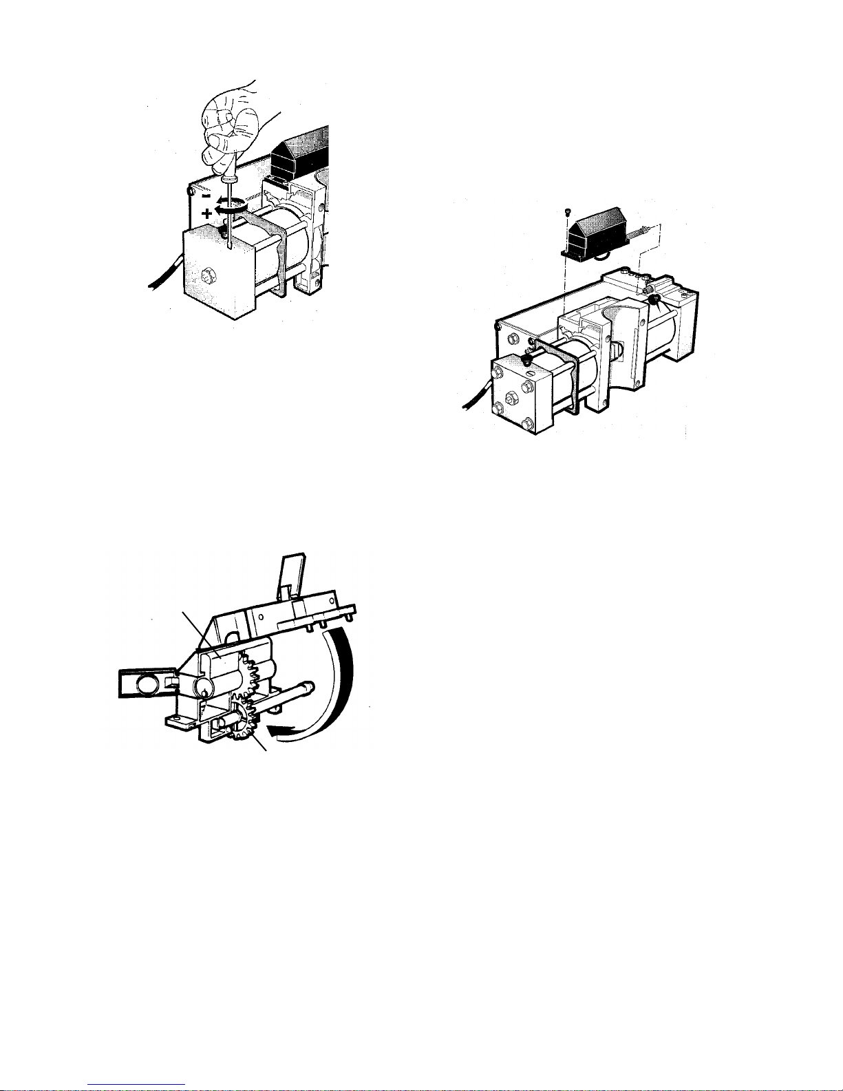
Figure 24. Turn the adjustment screw
clockwise to increase the braking intensity
and counter-clockwise to decrease the
braking intensity
The brass rod that extends from the plastic gear
assembly and out of the black plastic housing has a 6mm hex head on the visible end. You need to slide this
hex head into the brass fitting of the 760 Operator that is
located on the same end as the bypass valve adjustment
screws (see Figure 29).
Once the head is seated, the rest of the Manual Release
assembly should fit into place on the top of the 760
Operator. Use the four screws in the parts package to
hold the Manual Release housing in place.
Figure 26. Install the Manual Release
mechanism
Brass gear
assembly
Plastic gear
assembly
Figure 25. Assemble the Manual Release
mechanism
24
Page 25
Installing an Extension Arm
Some gate installations do not meet the geometrical
constraints shown in Figure 4. In those situations, the
760 Extension Arm option can be used to install a 760
operator.
The geometrical constraint for using the 760 Extension
Arm is that the center of the splined shaft on the
mounting box must be within 6 in. (15.25 cm) of the
axis of rotation of the gate leaf.
WARNING! The farther away the splined shaft is from
the gate's axis of rotation, the greater the risk of danger
from pinch points.
Install the mounting box so that the splined shaft is as
near as possible to the gate's rotation axis and is directly
beneath the center of the fully closed gate leaf.
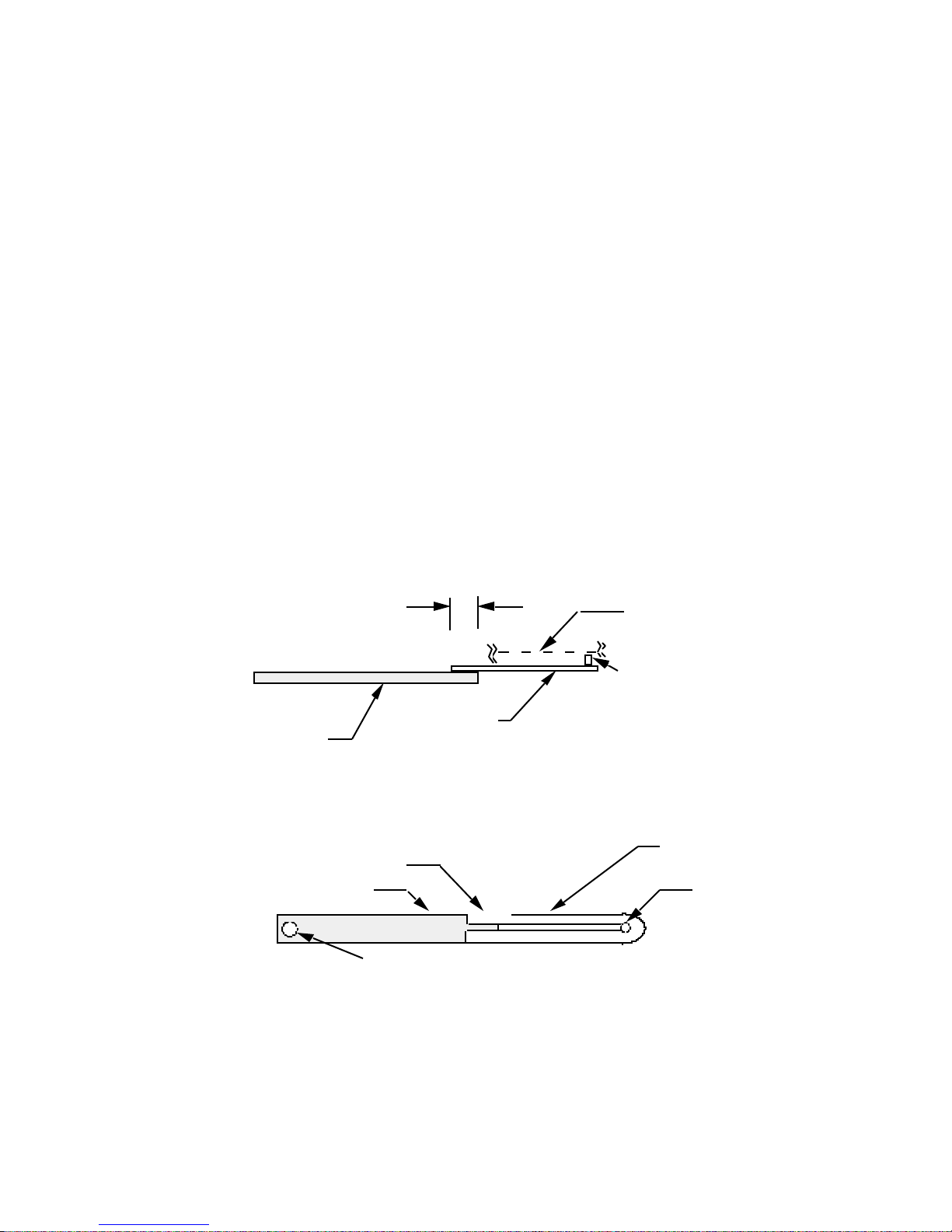
You need to position the extension collar (see Figure
27) so that it smoothly slides within the extension U
from the fully closed to the fully opened position. Note
that the position of the extension collar is affected by
the overlap of the extension bar and extension U.
Attach the 760 extension collar to the bottom of the gate
leaf with a 7/16 in. bolt.
Weld together the extension bar and extension U
according to Figure 30.
Caution: Do not weld anything to or on the inside of
the sleeve of the splined shaft.
Next, weld the outside of the sleeve for the splined shaft
solidly to the inside of the hole in the end of the
extension bar.
Follow the rest of the instructions for installing the 760
Operator. With an extension arm, you need not worry
about installing a gate leaf shoe nor about installing the
gate leaf in the shoe. Instead, you will install one end of
the welded extension arm over the splined shaft and the
other end around the extension collar.
In addition, you will need to provide a washer beneath
the extension collar to keep the extension U from falling
off the collar. You also need to shield any pinch points
around the extension arm for safe operation.
(a) Minimum overlap of
2 1/2 in. (6.4 cm)
750 extension U
750/ 760
750 extension
extension bar
bar
(b)
Minimum overlap of
2 1/2 in. ( 6.4 cm)
Extension bar
750/ 760
extension U
Hole in the extension bar fits around and
is welded to the outside of the sleeve of
the splined shaft
Figure 27. The 760 Extension Arm, (a) side view and (b) top view
Bottom of
gate leaf
750/ 760 extension collar
750 extension
collar is attached
is attached to the bottom of
to the bottom of
the gate leaf
the gate leaf
Extension U
Extension
collar slides
within
extension U
25
Page 26

Maintenance
The 760 Operator
The FAAC recommended maintenance schedule varies
according to the frequency of use of the operators,
whether lightly used operators (once or twice an hour)
or heavily used operators (many cycles per hour).
Operators used in a humid/ salt air climate should
follow the heavy duty use schedule.
Check the oil.
To check the oil level correctly, remove the oil filler cap
on the 760 Operator. The oil level should be at or just
below the opening of the filler hole.
Light duty use: check once per year
Heavy duty use: check every 6 mo
Change the oil.
Changing the oil completely in the hydraulic system of
the 760 Operator requires removing the 760 Operator
from its installed position. (Do not remove the gate or
the mounting box with the pinion and splined shaft.)
Drain the oil out the oil filler hole before filling the
operator to just below the hole. Remount the operator.
Light duty use: change every 4 yr
Heavy duty use: change every 2 yr
Heavy duty use: every 2 yr
Bleed the Hydraulic System
The 760 Operator has had all air bled from its hydraulic
system when it is shipped to you. The only time it
should be necessary to bleed the 760 Operator is after
you repair the hydraulic system.
To bleed the hydraulic system of air that might cause
bouncy or jerky operation do the following:
1. Remove the access cover to the mounting
box.
2. Give an open signal to the gate.
3. While the gate is opening unscrew the
opening bleed screw (see Figure 23).
4. Wait until only clean, bubble-free oil flows
out the bleed screw.
5. Tighten the opening bleed screw.
6. Give a closing signal to the gate.
7. While the gate is closing, unscrew the closing
bleed screw.
8. Wait until only clean, bubble-free oil flows
out the bleed screw.
9. Tighten the closing bleed screw.
Check the pressure settings.
Light duty use: check once per year
Heavy duty use: check every 6 mo
Rack and Pinion
When you remove the 760 Operator from the mounting
box to change the hydraulic oil, grease the rack and the
pinion.
Light duty use: every 4 yr
Repeat steps 1–8 again after five minutes if necessary.
Then be sure to slowly fill the oil level to just below the
filler hole.
The Control Panel
The control panel requires no maintenance.
26
Page 27

Troubleshooting
WARNING!
Before you do any work on the control panel, be sure to turn off the main power.
Problem: The gate does not respond to an activating
signal.
Solution:
Verify that you have correctly wired the operator to the
control panel.
Verify that the LED DL3 is on. If it is not illuminated,
then check the fuses on your control panel.
If the LED DL3 is not illuminated and your fuses are
okay, then the stopping device is being triggered and is
preventing the gate from responding to your signal. If
you have no stopping device installed, then be sure you
have installed a jumper across the appropriate terminals.
Verify that your activating device works properly. Either
DL1 or DL2 (depending on your gate design) should
illuminate when you signal the gate to close (or open)
and LED DL3 should be on. If either DL1 or DL2 does
not illuminate when you signal the gate, then the
problem may be in your activating device. Short across
the appropriate terminals. If the short causes the gate to
close (or open), then the problem is in the activating
device. Repair or replace the device.
Problem: The radio controlled opener does not open
the gate.
Solution:
Check the light on the front of the remote transmitter. It
should illuminate when you signal the gate. If it does not
illuminate and if the batteries are okay, repair or replace
the transmitter.
Increase the bypass pressure in small 1/4 turn increments
to see if the hydraulic system needs more pressure.
Problem: The gate opens but does not close.
Solution:
Make sure you have selected the desired operating
mode.
Verify that the reversing devices are working properly.
DL4 or DL5 should illuminate when a reversing device
is triggered. If either does not illuminate, then one of
your reversing devices is preventing the gate from responding to your signal. Check your reversing devices.
If no reversing devices are installed, make sure a circuit
is installed between appropriate terminals.
If the motor is running, insure that the bypass valves are
correctly adjusted. Increase the bypass pressure in small
1
/4 turn increments to see if the hydraulic system needs
more pressure.
Problem: The gate does not fully open (or close).
Solution:
Increase the bypass pressure(s) to see if the hydraulic
system needs more pressure.
Check the operator's motor run time selection. You
should set a time that is just longer than the rated speed
of your model of operator. For example, because the 760
CBAC has a rated opening time of 17 sec, you should
select a time that is just longer than the opening time.
Verify that the wiring is correct for the radio controlled
device and the antenna.
Check DL1 and DL2. One should illuminate when the
transmitter button is pressed.
Determine if the fault is in the receiver by temporarily
connecting a push button device across the appropriate
terminals. If such a push button device opens the gate,
repair or replace the receiver.
Problem: The gate doesn't open (or close) though the
motors are running.
Solution:
Make sure that the motor is running in the right direction, and make sure the Manual Release mechanism has
fully engaged the hydraulic system.
Check to see that there are no obstructions in the path of
the gate or that the hinges are not binding.
Problem: The operator doesn't work smoothly and
the gate jerks as it opens and closes.
Solution:
Check the oil level in the operator.
Make sure the Manual Release mechanism has fully
engaged the hydraulic operation of the operator.
Bleed the air from the hydraulic system by cycling the
gate (opening and then closing) 10 times and pausing for
a couple of minutes between cycles.
Make sure that a flexible gate leaf is not the problem. If
the gate leaf flexes, then stiffen the gate or use a slower
operator.
27
Page 28
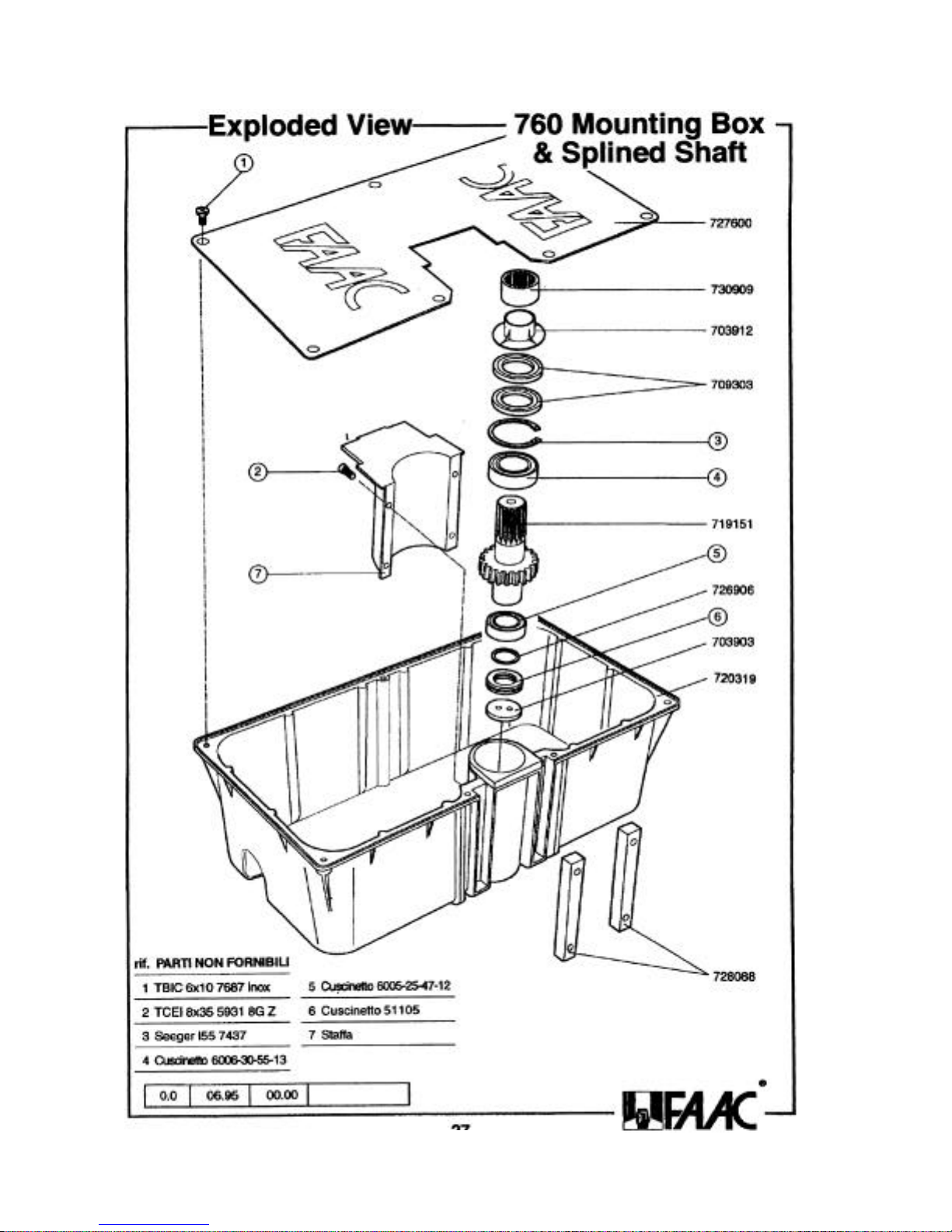
Page 29
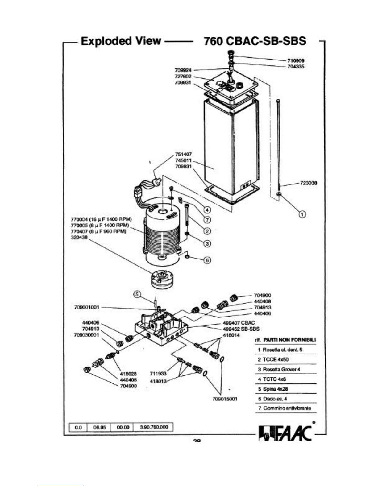
UL strain relief
kit (2167A*):
710914
710915
709020002
703930
Page 30
Page 31

Limited Warranty
760 IM, 04/01
To the original purchaser only: FAAC International, Inc., warrants, for twenty-four (24) months from the date of invoice, the
gate operator systems and other related systems and equipment manufactured by FAAC S.p.A. and distributed by FAAC
International, Inc., to be free from defects in material and workmanship under normal use and service for which it was intended
provided it has been properly installed and operated. FAAC International, Inc.'s obligations under this warranty shall be limited to
the repair or exchange of any part of parts manufactured by FAAC S.p.A. and distributed by FAAC International, Inc. Defective
products must be returned to FAAC International, Inc., freight prepaid by purchaser, within the warranty period. Items returned will
be repaired or replaced, at FAAC International, Inc.'s option, upon an examination of the product by FAAC International, Inc.,
which discloses, to the satisfaction of FAAC International, Inc., that the item is defective. FAAC International, Inc. will return the
warranted item freight prepaid. The products manufactured by FAAC S.p.A. and distributed by FAAC International, Inc., are not
warranted to meet the specific requirements, if any, of safety codes of any particular state, municipality, or other jurisdiction, and
neither FAAC S.p.A. or FAAC International, Inc., assume any risk or liability whatsoever resulting from the use thereof, whether
used singly or in combination with other machines or apparatus.
Any products and parts not manufactured by FAAC S.p.A. and distributed by FAAC International, Inc., will carry only the
warranty, if any, of the manufacturer. This warranty shall not apply to any products or parts thereof which have been repaired or
altered, without FAAC International, Inc.'s written consent, outside of FAAC International, Inc.'s workshop, or altered in any way so
as, in the judgment of FAAC International, Inc., to affect adversely the stability or reliability of the product(s) or has been subject to
misuse, negligence, or accident, or has not been operated in accordance with FAAC International, Inc.'s or FAAC S.p.A.'s
instructions or has been operated under conditions more severe than, or otherwise exceeding, those set forth in the specifications for
such product(s). Neither FAAC S.p.A. or FAAC International, Inc., shall be liable for any loss or damage whatsoever resulting,
directly or indirectly, from the use or loss of use of the product(s). Without limiting the foregoing, this exclusion from liability
embraces a purchaser's expenses for downtime or for making up downtime, damages for which the purchaser may be liable to other
persons, damages to property, and injury to or death of any persons. Neither FAAC S.p.A. or FAAC International, Inc., assumes nor
authorizes any person to assume for them any other liability in connection with the sale or use of the products of FAAC S.p.A. or
FAAC International, Inc. The warranty herein above set forth shall not be deemed to cover maintenance parts, including, but not
limited to, hydraulic oil, filters, or the like. No agreement to replace or repair shall constitute an admission by FAAC S.p.A. or
FAAC International, Inc., of any legal responsibility to effect such replacement, to make such repair, or otherwise. This limited
warranty extends only to wholesale customers who buy directly through FAAC International, Inc.'s normal distribution channels.
FAAC International, Inc., does not warrant its products to end consumers. Consumers must inquire from their selling dealer as to the
nature and extent of that dealer's warranty, if any.
This warranty is expressly in lieu of all other warranties expressed or implied including the warranties of
merchantability and fitness for use. This warranty shall not apply to products or any part thereof which have
been subject to accident, negligence, alteration, abuse, or misuse or if damage was due to improper installation
or use of improper power source, or if damage was caused by fire, flood, lightning, electrical power surge,
explosion, wind storm, hail, aircraft or vehicles, vandalism, riot or civil commotion, or acts of God.
 Loading...