

Page 1
Installation Guide & User Manual
Digital Surveillance Software
Version 4.0 HiDef
Page 2

Table of Contents
1 System Requirements 5
1.1 Professional Grade Minimum System Requirements 5
1.2 Business Grade Minimum System Requirements 5
2 Quick Start Guide 7
2.1 Identifying Your EZWatch Pro Capture Card 7
2.1.1 Professional Grade Capture Card 7
2.1.2 Business Grade Capture Card 7
2.2 Hardware Installation 8
2.2.1 Installing the EZWatch Pro Capture Card 8
2.3 Software Installation 9
2.3.1 Installing the EZWatch Pro 4.0 Software and Capture Card Drivers 9
2.4 Main Console Introduction 12
2.4.1 Main Console Operation Buttons 13
3 Software User Manual 15
3.1 Schedule Conguration 15
3.1.1 Always Record 16
3.1.1.1 24 Hours, Always Record 16
3.1.1.2 Non-24 Hour, Always Record 16
3.1.2 Record on Event 16
3.1.3 Record on Motion 16
3.1.4 Comprehensive Schedule Conguration 18
3.2 Encoding Options Conguration 19
3.2.1 Start Conguration 23
3.3 Edit Mode 25
3.4 Operation Mode 27
3.4.1 Device and Map Tree List 27
3.4.2 Information and Preview Window 28
3.5 Conguration Button 28
3.6 Setting 29
3.6.1 General Setting Tab 29
3.6.2 Camera Setting Tab 31
3.6.3 Input/Output (I/O) Device Conguration 34
3.6.4 PTZ Conguration Tab 35
3.6.5 Main Console PTZ Control Panel 37
3.6.6 Hotline Conguration Tab 38
3.6.7 User Account Conguration Tab 39
3.6.8 Privilege 40
3.6.9 Address Book Tab 40
3.6.10 Monitor Display Tab 41
3.6.11 Joystick Tab 42
3.7 Additional Conguration Menu Options 43
Page | 1 Table of Contents
Page 3

3.7.1 Save/Load Conguration 44
3.7.2 Video Source (Business Grade Only) 44
3.7.3 Counting Application 44
3.7.4 POS Application 46
3.8 Counting Application Tab 47
3.9 Counting Application (Diagram) Tab 47
3.10 Point Of Sale (POS) Log 48
3.11 Backup System 48
3.12 Deleting Recorded Video and Information 50
3.13 About Main Console 50
3.14 Network Service Conguration 51
3.15 Live Streaming Server 52
3.15.1 Main Tab 52
3.15.2 Black/White List Tab 54
3.15.3 Performance Tab 55
3.16 Remote Playback Server 55
3.16.1 Main Tab 56
3.16.2 Black/White List Tab 57
3.16.3 Performance Tab 57
3.17 3GPP Server 57
3.17.1 Main Tab 57
3.18 Remote Desktop Server 58
3.18.1 Main Tab 58
3.19 Central Management Server 59
3.20 Playback Conguration 59
3.21 Playback Toolbars 60
3.21.1 Open Record 63
3.21.2 DateTime Search Dialog Window 63
3.21.3 To Withdraw the Record 65
3.22 Alarm Event Types 66
3.22.1 General Motion 66
3.22.2 Foreign Object 66
3.22.3 Missing Object 67
3.22.4 Lose Focus 67
3.22.5 Camera Occlusion 67
3.23 Remote Server 67
3.24 Playback Setting 69
3.24.1 General Tab 69
3.24.2 On Screen Display (OSD) Tab 70
3.24.3 Point Of Sale (POS) Tab 70
3.25 Enhancement 71
3.25.1 Filter Setting 71
3.26 Save Video 71
3.27 Save Image 72
2 | Page Table of Contents
Page 4

3.28 Print 73
3.29 Backup 73
3.30 Log Viewer 74
3.31 Smart Guard Conguration 74
3.31.1 Event Conguration 75
3.31.2 Assign a Camera Event 75
3.32 Event - Signal Lost 76
3.32.1 Basic Tab 76
3.33 Event - General Motion 77
3.33.1 Basic Tab 77
3.33.2 Advanced Tab 78
3.34 Event - Foreign Object 79
3.34.1 Basic Tab 79
3.34.2 Advanced Tab 80
3.35 Event - Missing Object 81
3.35.1 Basic Tab 81
3.35.2 Advanced Tab 82
3.36 Event - Lose Focus 83
3.36.1 Basic Tab 83
3.36.2 Advanced Tab 84
3.37 Event - Camera Occlusion 85
3.37.1 Basic Tab 85
3.37.2 Advanced Tab 86
3.38 Event - Digital Input 87
3.39 Action 88
3.39.1 Action Type 88
3.40 Remote Access Conguration 90
3.40.1 Anti-Virus Programs 91
3.40.2 Software Firewalls 91
3.40.3 Hardware Firewalls 91
3.40.4 Is your modem a router? 91
3.40.5 My modem is NOT a router 92
3.40.6 My modem IS a router 92
3.40.7 Setting up Port Forwarding 93
3.40.7.1 Business Connections 93
3.40.7.2 Personal Connection 94
3.41 Remote Access Connection 94
3.41.1 Installing the Remote Live Viewer 94
3.42 LiveView Setting (Site Setup) 96
3.42.1 Server Tab 96
3.42.2 Group Tab 97
3.43 On Screen Display (OSD) Tab 98
3.44 Joystick Tab 98
3.45 Remote Live Viewer Console 99
Page | 3 Table of Contents
Page 5

3.45.1 Internet Explorer Web View 100
3.45.2 Remote Desktop Viewer 101
3.45.2.1 Installing the Remote Desktop Viewer 101
3.45.3 DBTools (Database) 102
4 “How To” Guides 105
4.1 How To Make a Twist-On BNC Video Cable Fitting 105
4.2 How To Wire a Multi-Camera Power Supply and Extend a Camera’s Power Cable 105
4.3 Camera Placement and Connection Tips 106
4.4 How To Set Up Internet Access Using EZWatchIP 107
4.5 How To Set Up Pan/Tilt/Zoom Cameras 109
4.5.1 Hardware Set Up for Netcom Module 109
4.5.2 Camera Settings 110
4.5.3 Software Set Up 111
5 FCC Compliance 115
5.1 FCC Compliance Statement 115
5.2 FCC Warning 115
6 License Agreement 117
6.1 Legal Agreement 117
6.2 Software Product License 117
6.2.1 Grant of License 117
6.2.2 Other Rights And Limitations 117
6.2.3 Termination 117
6.2.4 Upgrades 117
6.2.5 Infringement & Copyright 117
6.2.6 Limits Of Liability 117
6.3 Trademark 118
6.4 Customer Support 118
6.4.1 EZWatch Pro Technical Support 118
7 List of Figures 119
4 | Page Table of Contents
Page 6
1 System Requirements
1.1 Professional Grade Minimum System Requirements
EZKIT-32PR EZKIT-16PR EZKIT-12PR EZKIT-8PR EZKIT-PR
CPU Intel
Core2Duo
2.0 GHz
RAM 1 GB 512 MB 512 MB 256 MB 256 MB
Hard Disk 750 GB 500 GB 320 GB 200 GB 160 GB
Motherboard Intel 845, 945, 965 chipset or above
(Intel Chipset and ASUS vendor recommended)
Display ATi Radeon 9200, nVIDIA GeForce FX-5200 or above.
(ATi recommended)
Resolution 704 x 480
OS Microsoft Windows 2000, XP, or Vista
Network (IP) 100 baseT or above (Gigabit LAN recommended)
1.2 Business Grade Minimum System Requirements
Intel
P4
3.0 GHz
Intel
P4
2.8 GHz
Intel
P4
2.4 GHz
Intel
Celeron
2.0 Ghz
EZKIT-32BU EZKIT-16BU EZKIT-12BU EZKIT-8BU EZKIT-BU
CPU Intel
Core2Duo
2.0 GHz
RAM 1 GB 512 MB 512 MB 256 MB 256 MB
Hard Disk 750 GB 500 GB 320 GB 200 GB 160 GB
Motherboard Intel 845, 945, 965 chipset or above
(Intel Chipset and ASUS vendor recommended)
Display ATi Radeon 9200, nVIDIA GeForce FX-5200 or above.
(ATi recommended)
Resolution 704 x 480
OS Microsoft Windows 2000, XP, or *Vista (*XP Compatibility Mode)
Network (IP) 100 baseT or above (Gigabit LAN recommended)
► Warning Please verify the performance of any PC on which you are
installing the EZWatch Pro video surveillance system. Failure to meet the
minimum computer requirements listed above may result in poor system
performance.
Intel
P4
3.0 GHz
Intel
P4
2.8 GHz
Intel
P4
2.4 GHz
Intel
Celeron
2.0 Ghz
Page | 5 System Requirements
Page 7

This Page is Blank
6 | Page
Page 8
2 Quick Start Guide
This Quick Start Guide is designed to help you get your EZWatch Pro surveillance system activated and
operational as quickly as possible.
2.1 Identifying Your EZWatch Pro Capture Card
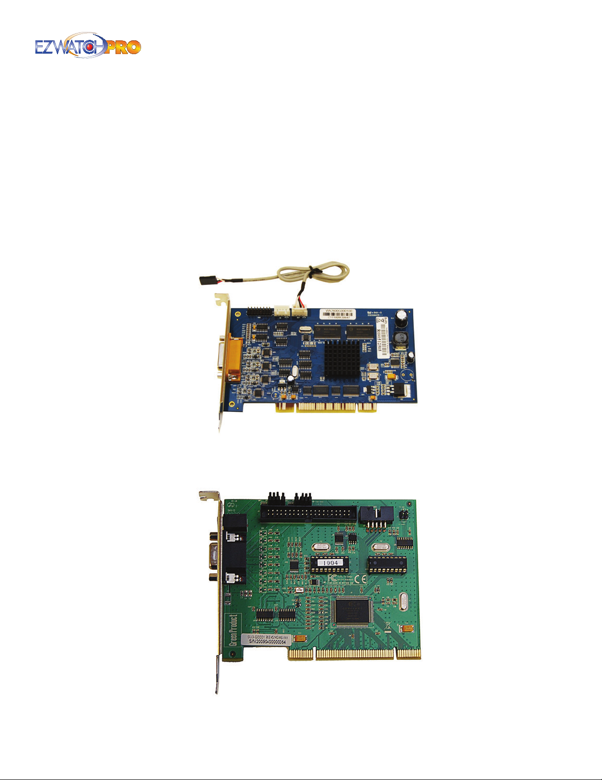
This section helps you identify the type of capture card you are installing. There are two types of
capture card recognizable by their size, shape, and color: Professional Grade Capture Card and
Business Grade Capture Card.
2.1.1 Professional Grade Capture Card
Fig. 1. Professional Grade Capture Card
2.1.2 Business Grade Capture Card
Fig. 2. Business Grade Capture Card
Page | 7 Quick Start Guide
Page 9
2.2 Hardware Installation
2.2.1 Installing the EZWatch Pro Capture Card
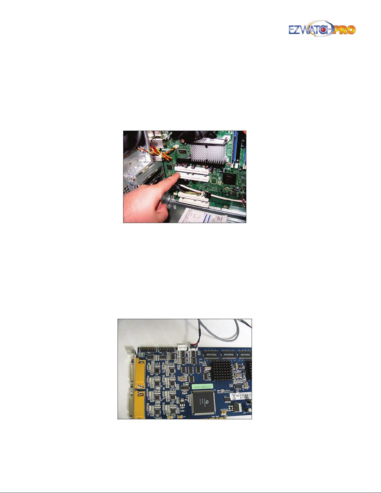
■ Step 1 Turn o your PC.
■ Step 2 Insert each capture card into an available PCI slot on your motherboard.
Fig. 3. Inserting a capture card into a PCI slot
► Note Each Professional Grade Capture Card includes an internal audio
connection cable. This cable connection is not required if you do not
intend to use the audio feature of the EZWatch Pro software. Instructions
on installing the internal audio cable are listed below.
► Note No audio cable connection is needed if you are using the Business
Grade Capture Card, as it is already built-in.
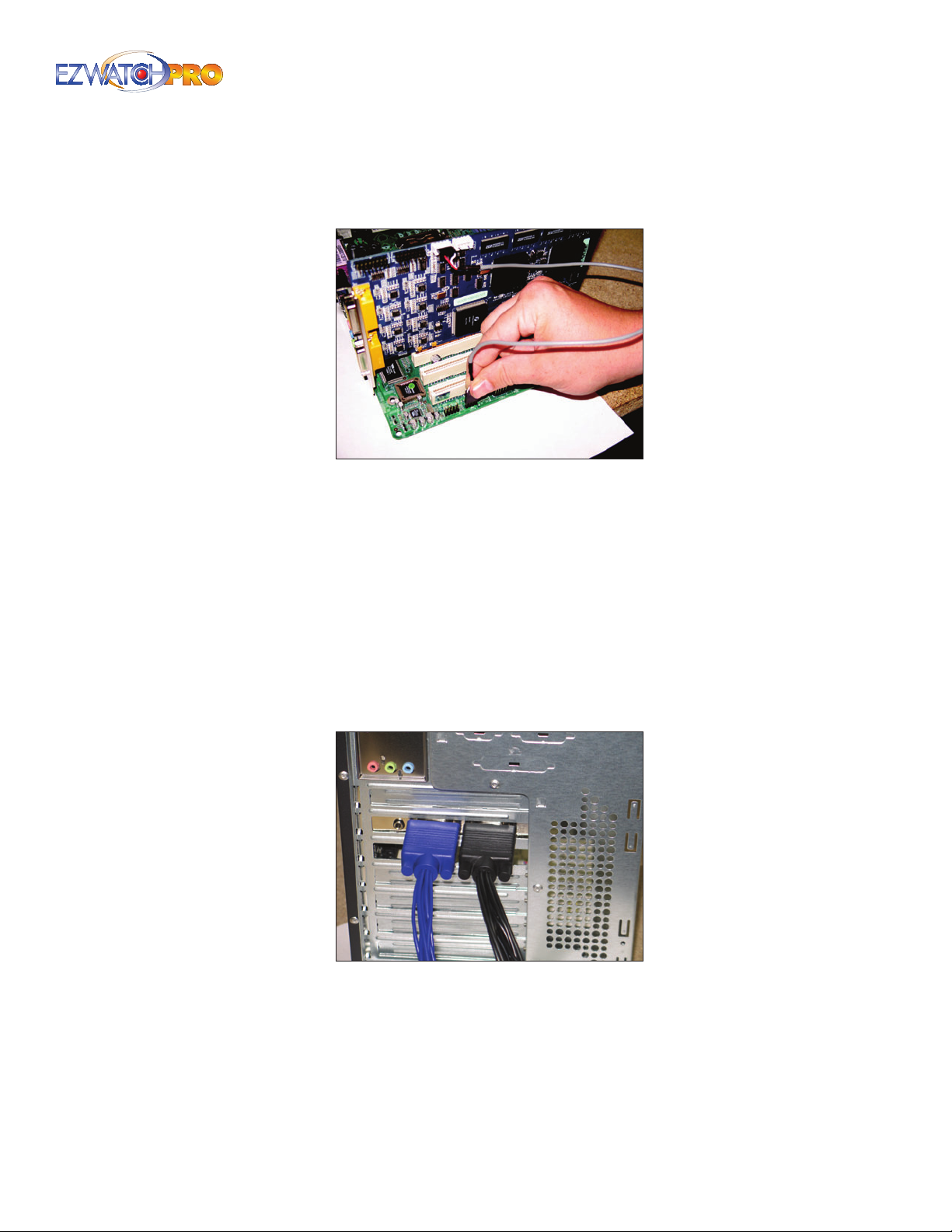
■ Optional (Professional Grade Only) Connect one end of the internal audio cable to the
OUT connection of the capture card.
Fig. 4. Connecting an internal audio cable to a capture
card
8 | Page Quick Start Guide
Page 10
Connect the opposite end of the cable to either an AUX or CD input on your motherboard or
sound card.
Fig. 5. Connecting an internal audio cable to a
motherboard
This cable connection allows you to monitor live audio through your PC.
■ Step 3 Connect the external video/audio cable splitter to the capture card.
Business Grade Capture Cards Each external video/audio cable splitter has one Audio Input
for every four Video Inputs. The video connections are labeled V1 through V4 and the audio
connection is labeled A1.
Professional Grade Capture Cards Each external video/audio cable splitter has one Audio Input
for every one Video Input. The video connections are labeled VID1 through VID4 and the audio
connections are labeled AID1 through AID4.
Fig. 6. External video/audio cable splitters connected to a
capture card
Page | 9 Quick Start Guide
Page 11
2.3 Software Installation
2.3.1 Installing the EZWatch Pro 4.0 Software and Capture Card
Drivers
■ Step 1 Insert the EZWatch Pro 4.0 Software CD into the CD-ROM or DVD-ROM drive of your
computer.
■ Step 2 The autoplay menu for the disc will be displayed. If it does not display, click on the My
Computer icon and locate the EZWatch Pro Software disc under Devices with Removable
Storage. Open the disc by double-clicking on the icon.
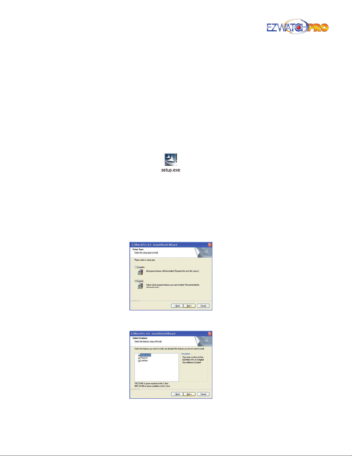
Locate the Setup.exe le to begin installing the EZWatch Pro Software.
Fig. 7. Setup.exe icon
■ Step 3 Follow the Windows Installation Wizard instructions. First select the language English and
click Next. Accept the Software License Agreement and click Next to continue. Type a Username
and Company name and click Next to continue. (If you do not have a company name simply use
your last name.)
■ Step 4 For initial installations, choose Complete and click Next. Choose Custom for computers
used only for remote viewing or playback. You may install the system to a preferred directory and
choose only the feature(s) you want to install to the PC.
Fig. 8. Choosing Custom install for remote viewing and
playback computers
Fig. 9. Selecting MainConsole, Playback, and LiveView for
Custom install
10 | Page Quick Start Guide
Page 12
■ Step 5 You will now see Ready to Install Program. Click on the Install button. The software will
now install automatically.
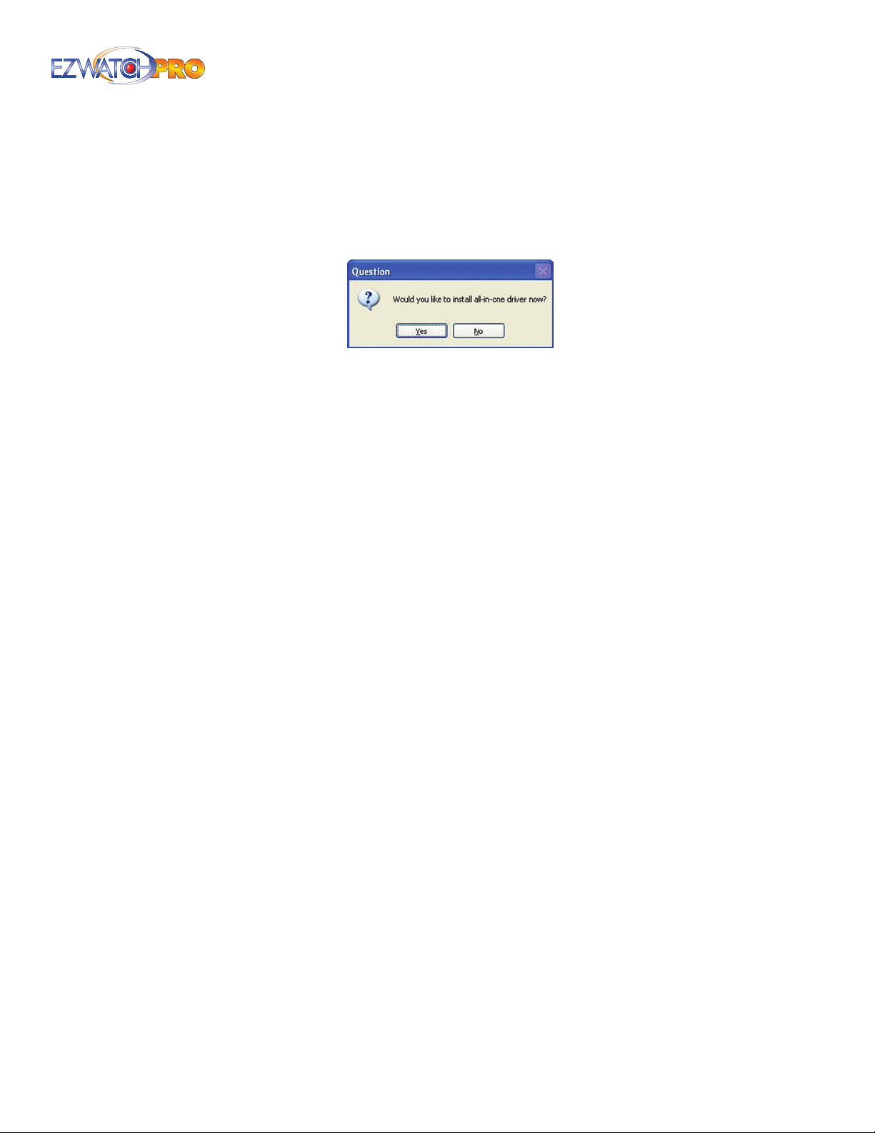
■ Step 6 After the software has been installed, a prompt will appear asking if you want to install
the drivers for the card. Click Yes on the prompt, then follow the on-screen instructions to
automatically install the drivers for your capture card(s).
Fig. 10. Installing all-in-one driver for capture cards
■ Step 7 After the drivers have been loaded, you are given the option to install Motherboard
Monitor 5 (MBM5). MBM5 is a completely optional program designed to allow you to monitor the
health of your computer while the camera system is in operation. It will allow you to keep an eye
on CPU temperature, motherboard temperature, etc. Please note that not all motherboard models
are supported. If you are unsure whether or not to use this feature, it is safe to just click No.
■ Step 8 The software is now installed. The last step is to assign a password to EZ Watch Pro 4.0.
The software will ask you to enter a password when you launch the Main Console program the
rst time. Go to Start, then All Programs, then go to the EZ Watch Pro 4.0 folder and click on
Main Console to launch the program. You will be required to enter your desired password twice.
The default username, admin, can be changed only after the software has been installed and
congured.
► Warning Please make a note of the default username 'admin' and your
chosen password. If this username/password is misplaced or forgotten,
you will be locked out of the Main Console. This will require a complete
uninstall and reinstall of your EZWatch Pro 4.0 Software. All existing
settings and congurations will be lost.
Page | 11 Quick Start Guide
Page 13
2.4 Main Console Introduction
The Main Console is used for camera viewing, activating scheduled recording, smart guard set up, and
conguring system settings.
Minimize
Button
Camera Images
Information Window
Exit
Button
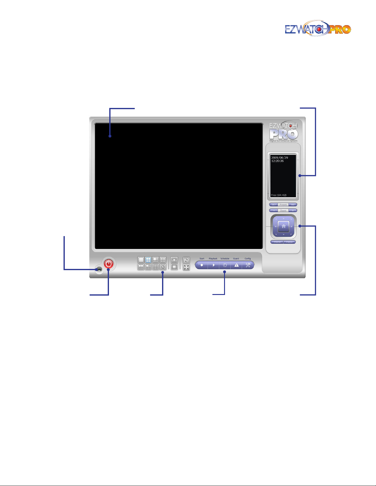
Fig. 11. Main Console window
Camera Images The real-time images of your cameras will be viewable here.
Information Window This will display date, time, free HD space, CPU temperature, fan speed, and
customized text.
► Note Some options (CPU Temperature, Fan Speed, etc.) may require MBM5
to be installed and congured.
Minimize Button Minimize the Main Console window.
Exit Button Shut down the Main Console or log out current user.
Screen Divisions Allocate the sub-screen display by clicking on the desired layout button. To
switch to single camera display, double click on a particular sub-screen. Double click on the screen
again to regain previous screen division layout.
12 | Page Quick Start Guide
Screen
Divisions
Operation
Icons
Pan/Tilt/Zoom
Camera Controls
Page 14
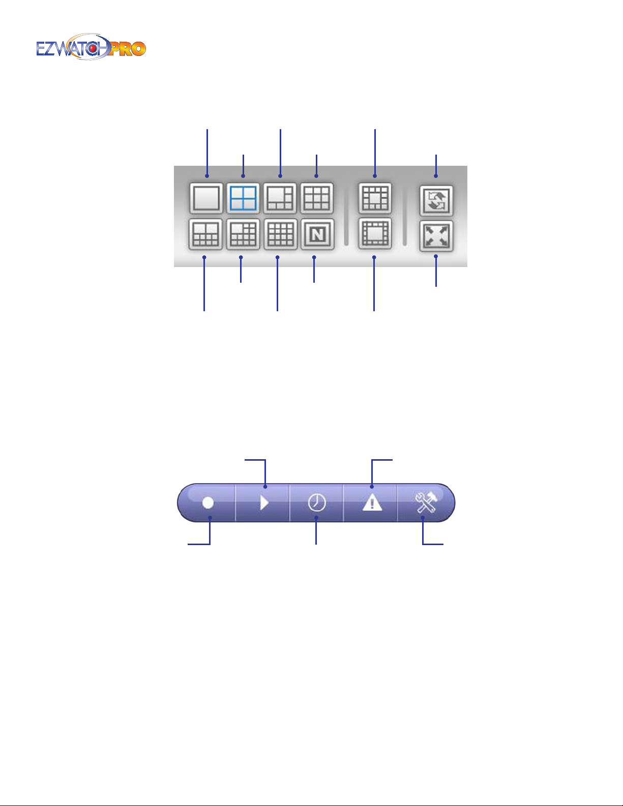
1 Screen 6 Screens
4 Screens 9 Screens
13 Screens
Rotate
all
Screens
13 Screens
10 Screens 16 Screens
Fig. 12. Screen division menu in Main Console
Operation buttons Refer to the next section for details.
Pan/Tilt/Zoom Camera Control This is used to control the movement and functions of PTZ
cameras. Refer to Main Console PTZ Cong in 3.6.5 Main Console PTZ Control Panel on Pg. 37 for
more details.
N screens
17 Screens
Switch to
Full
Screen
2.4.1 Main Console Operation Buttons
Playback
Start
Fig. 13. Operation buttons in the Main Console
Schedule
Guard
Cong
Start This button allows you to activate/deactivate the various services within the Main Console.
Key Features
Manually Start/Stop Recording Schedules and Smart Guard System (3.2.1 Start
•
Conguration on Pg. 23)
Lock the Main Console System (3.2.1 Start Conguration on Pg. 23)
•
E-Map Conguration (3.2.1 Start Conguration on Pg. 23)
•
Page | 13 Quick Start Guide
Page 15

Playback This button allows you to search and view recorded video.
Key Features
Playback Recorded Video (3.20 Playback Conguration on Pg. 59)
•
Export and Save Individual Video Files (3.26 Save Video on Pg. 71)
•
Backup of Multiple Video Files to a DVD/CD/HDD (3.29 Backup on Pg. 73)
•
Schedule This button congures the recording schedules and sets up the encoder conguration.
Key Features
Motion Detection Recording (3.1.3 Record on Motion, Pg. 16)
•
Schedule Recording (3.1 Schedule Conguration, Pg. 15)
•
Resolution and Frame Rate Settings (3.2 Encoding Options Conguration, Pg. 20)
•
Guard This button allows you to add/edit type(s) of events that you want to detect and automate
notications.
Key Features
Missing or Foreign Object, Video Loss, and Other Events (3.31 Smart Guard
•
Conguration on Pg. 74)
Sound/Alarm, Phone Call, E-Mail, and Other Notications (3.39 Action on Pg. 88)
•
Cong This button allows you to congure the general settings which determine the overall
functionality of the Main Console.
Key Features
User Account Settings (3.6.7 User Account Conguration Tab on Pg. 39)
•
Video Storage Conguration (3.6 Setting on Pg. 29)
•
Network/Remote Viewing Services (3.14 Network Service Conguration on Pg. 51)
•
Auto Startup of Services (3.6 Setting on Pg. 29)
•
IP Camera Conguration (IP Camera Conguration on Pg. 32)
•
Saving and Loading Personal Settings (3.7 Additional Conguration Menu Options on
•
Pg. 43)
Pan/Tilt/Zoom Camera Conguration (3.6.4 PTZ Conguration Tab on Pg. 35)
•
14 | Page Quick Start Guide
Page 16
3 Software User Manual
3.1 Schedule Conguration
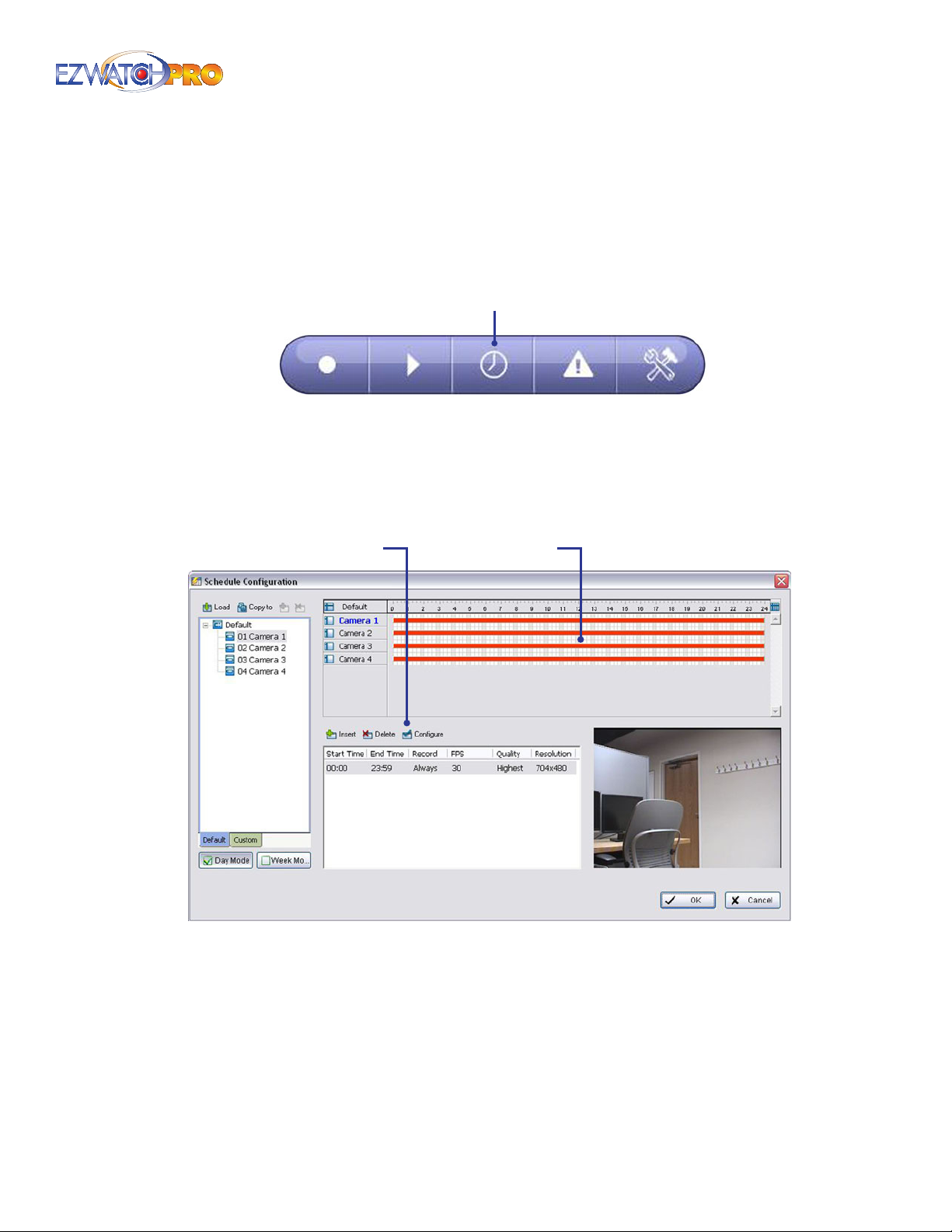
Launch the Schedule Conguration window by clicking the Schedule button in the Main Console.
Schedule
Fig. 14. Schedule Button in Main Console Operation menu
bar
By default, the initial recording schedule for each camera is set to 24 hours, Always Record, as shown
in the Time Table of the Schedule Conguration window in Fig. 15. The red bars in the Time Table
indicate each camera is recording 24 hours.
Congure Time Table
Fig. 15. Schedule Conguration window
You can modify or add dierent types of recording schedules for each camera using the Congure
button. The three (3) dierent types of recording schedules are Always Record, Record on Event, and
Record on Motion.
Page | 15 Software User Manual
Page 17

3.1.1 Always Record
3.1.1.1 24 Hours, Always Record
If the default Always Record is selected, the camera will record 24 hours. This selection is denoted by a
solid red indicator line in the Time Table of the Schedule Conguration window, as shown in Fig. 15.
3.1.1.2 Non-24 Hour, Always Record
Each camera can be congured to Always Record for a schedule less than 24 hours, e.g., between 6:00
AM and 6:00 PM (18:00).
■ Step 1 Select Camera 2 and press the Congure button in the Schedule Conguration window, as
shown in Fig. 15.
■ Step 2 Change the Start Time and End Time to 6:00 and 18:00, respectively, in the Time eld set of
the Encoding Options window (Fig. 16). Click OK to return to the Schedule Conguration window.
The new Always Record period will be displayed as a (shorter) red indicator line in the Time Table.
3.1.2 Record on Event
Each camera can be congured to Record on Event for 24 hours or any shorter duration. For event
types, please see 3.22 Alarm Event Types, Pg. 66.
■ Step 1 Select desired camera and press the Congure button in the Schedule Conguration
window (see Fig. 15).
■ Step 2 Select the Record on Event option in the Mode eld set of the Encoding Options window
(Fig. 16). Click OK to return to the Schedule Conguration window. The new Record On Event
period will be displayed as a blue indicator line in the Time Table.
3.1.3 Record on Motion
Each camera can be congured to Record on Motion for 24 hours or any shorter duration.
■ Step 1 Select desired camera and press the Congure button in the Schedule Conguration
window (see Fig. 15).
■ Step 2 In the Time eld set of the Encoding Options window, adjust the Start Time and End Time
to the desired duration.
16 | Page Software User Manual
Page 18
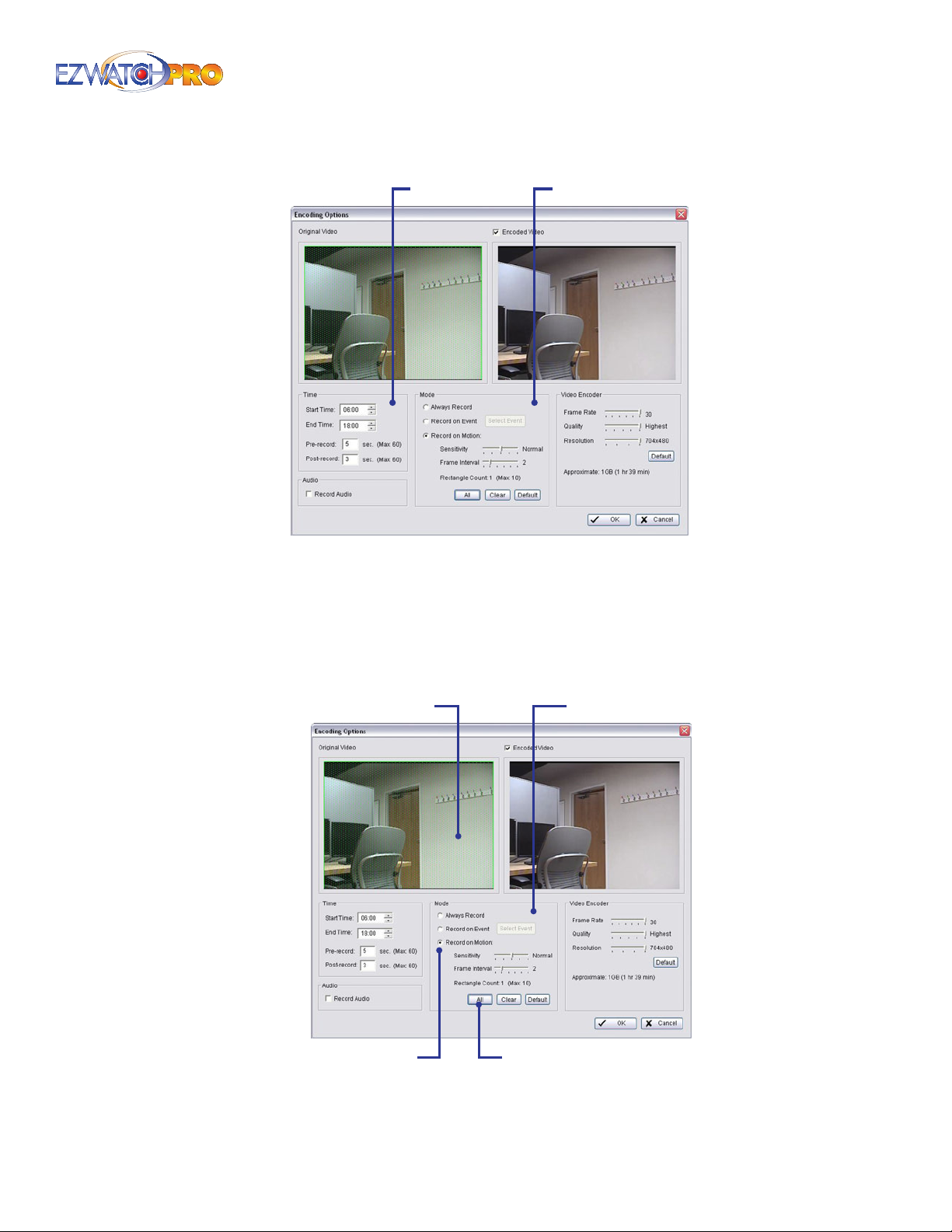
Time Field Set Mode Field Set
Fig. 16. Time eld set of the Encoding Options window
■ Step 3 In the Mode eld set, choose the Record On Motion option.
■ Step 4 Next, click All to select the entire viewing area for motion detection. You can also limit the
motion detection area by clicking on the original video signal and dragging the highlighter over
the desired area. Multiple areas can be chosen by continuing to drag the highlighter over other
sections of the screen Original Video Signal screen until all desired areas have been highlighted.
Mode Field SetOriginal Video Signal
Record on Motion
Fig. 17. Record on Motion option in the Encoding Options
window
All
Page | 17 Software User Manual
Page 19
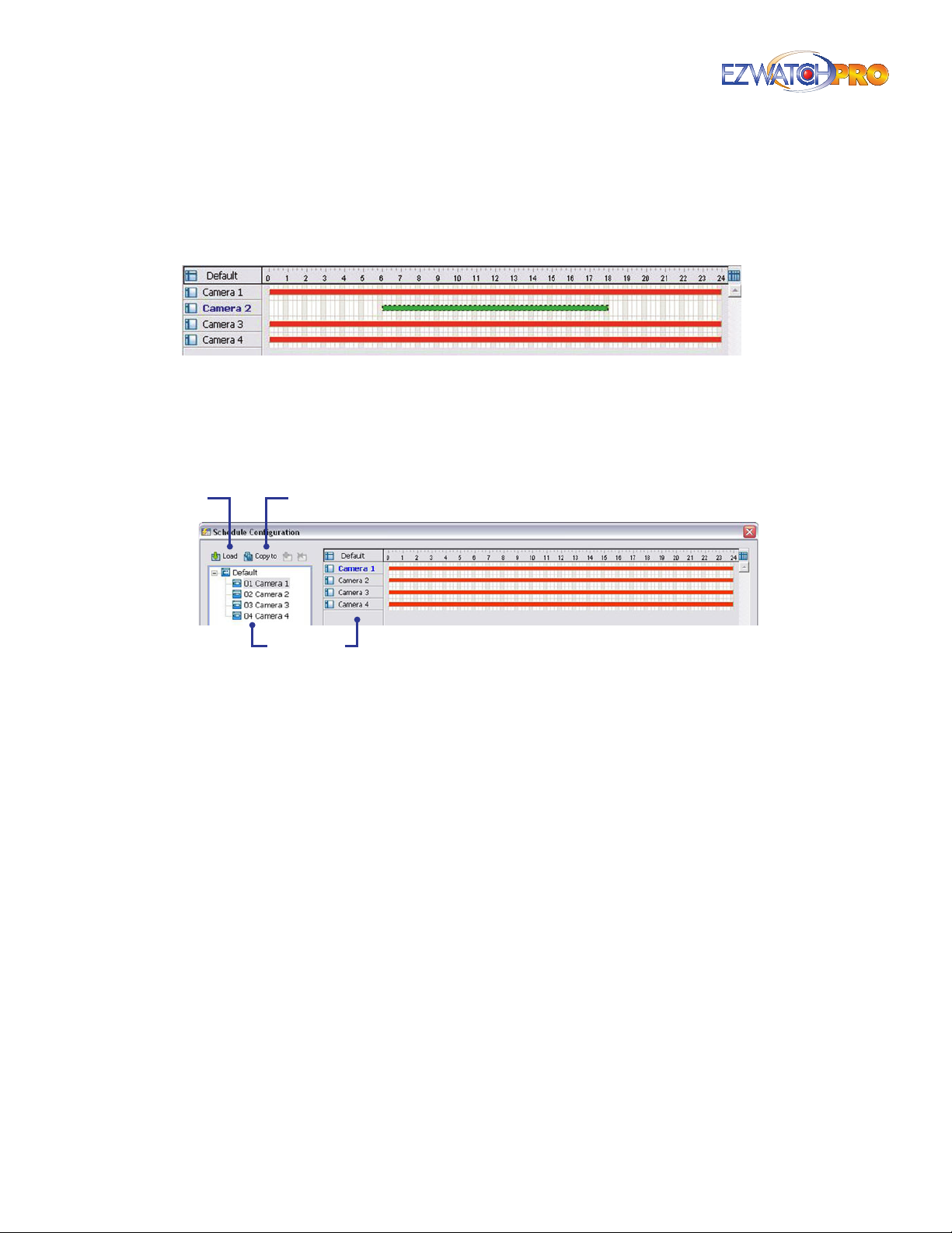
■ Step 5 Select appropriate Sensitivity and Frame Interval, or maintain the default values.
■ Step 6 Click OK to return to the Schedule Conguration window. The new Record On Motion
period will now be displayed as a green indicator line as illustrated in the Time Table of the
Schedule Conguration window of Fig. 18.
Fig. 18. Time Table of the Schedule Conguration window
The red bars indicate an 'Always Record' schedule and the green bar indicates a 'Record On Motion'
schedule.
3.1.4 Comprehensive Schedule Conguration
Load
Copy To
Cameras
Fig. 19. Top View of Schedule Conguration window
Copy To This feature allows you to copy one cameras schedule and conguration to any other
camera(s).
Load This feature allows you to import schedule recording presets. This is useful if you are copying
a schedule from another computer.
Regular Mode Video recording 24 hours a day with the setting of 30 FPS, normal video quality
and normal resolution.
Oce Mode Video recording from 8:00 AM to 8:00 PM with 30 FPS, normal video quality and
normal resolution.
Shop Mode Video recording from 10:00 AM to 10:00 PM with 30 FPS, normal video quality and
normal resolution.
High Security Mode Video recording 24 hours a day with the setting of 30 FPS, highest video
quality and normal resolution.
Disk Saving Mode Motion detection recording 24 hours a day with the setting of 30 FPS,
normal video quality, and normal resolution.
Minor Mode Motion detection recording 24 hours a day with the setting of 15 FPS, low video
quality, and low resolution.
18 | Page Software User Manual
Page 20
Insert
Delete
Custom
Holiday
Default
Day Mode Week Mode
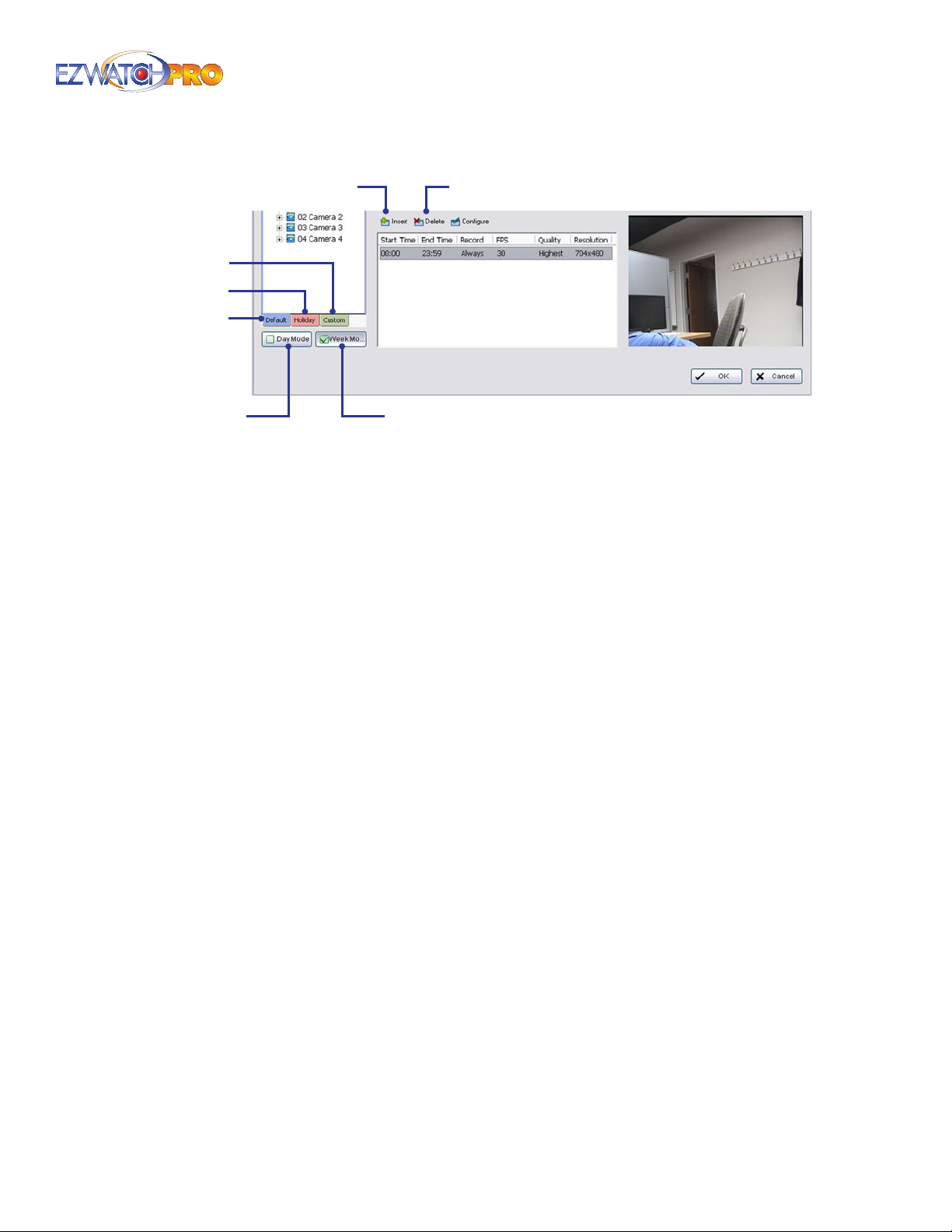
Fig. 20. Lower half of Schedule Conguration window
Day Mode Schedule the cameras to turn the recorder on and o at the same time every day
according to your settings. The recording schedule will disregard specic days of the week and
assume the same schedule every day.
Week Mode Schedule the cameras for each day of the week dierently. Additionally, you may
assign extra holidays under the Week Mode.
Custom You can assign a particular date(s) on which the system will work according to a
specic schedule dierent from the other dates.
Holiday You can assign holidays when the system will work according to the current setting of
Sunday.
Default Follow the same process to set up the schedule for every day in the week.
Insert This feature allows you to manually add a schedule into the Time Table. Left-click and
draw across the Time Table to create a gray bar indicating the scheduled time. Once the
desired time is created, then click the Insert Button to add the schedule. You can customize
this schedule further by using the Congure button.
Delete This allows you to delete any existing recording schedules.
Page | 19 Software User Manual
Page 21
3.2 Encoding Options Conguration
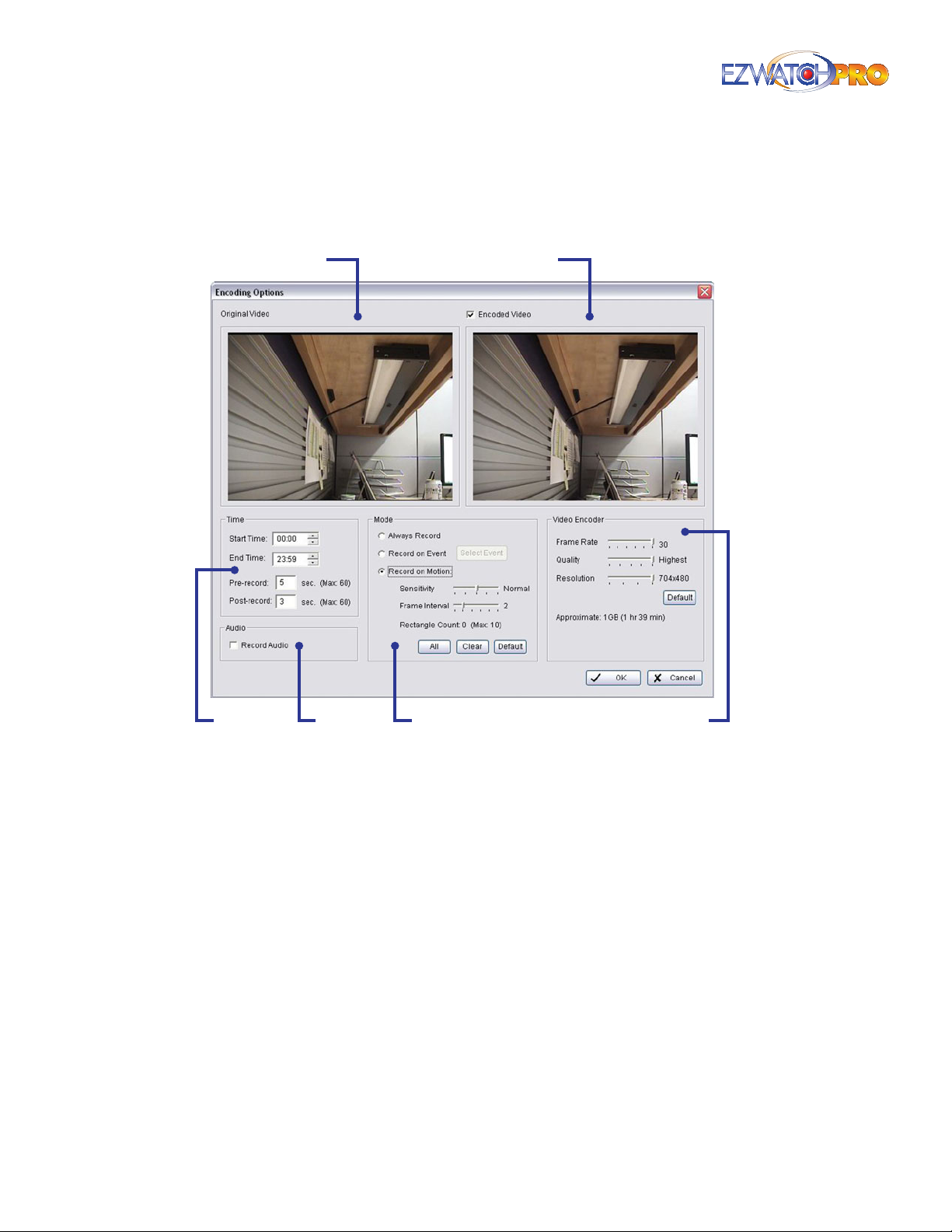
For the following features of the Encoding Options window, please refer to Fig. 21.
Encoded VideoOriginal Video
Time Video EncoderMode
Fig. 21. Encoding Options window
Original Video This window is a live view of the selected camera.
Encoded Video Checking this option will provide a preview of your recorded video based on your
encoding options (Frame Rate, Quality and Resolution).
Start/End Time This determines when the cameras are set to start and stop recording. You can
adjust the times here, with your keyboard or with the up and down arrows to the right of the text
box (see Fig. 22).
Pre-record/Post-record This feature saves the specied amount of time before and after a clip.
For example, to set up a 5 second pre-record time means the system will start saving the recording
data 5 seconds before the event happens. The system must be set to Event or Motion recording for
these options to function.
Audio
20 | Page Software User Manual
Page 22
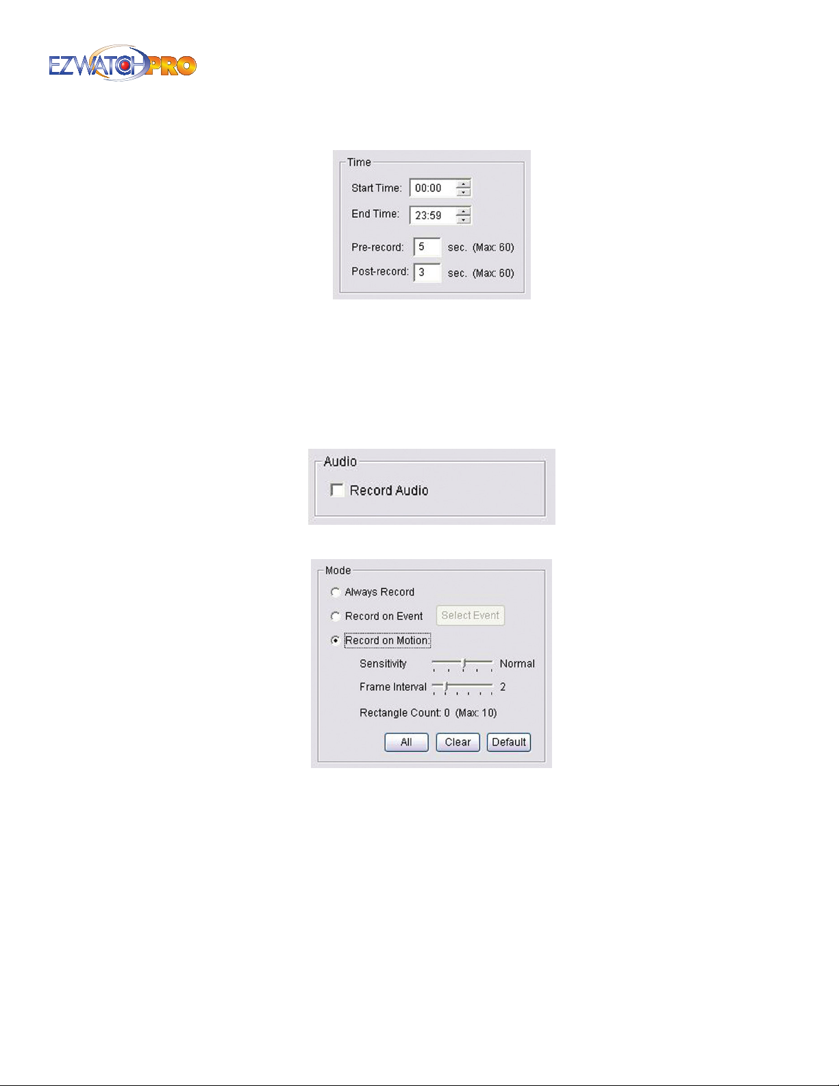
Fig. 22. Time eld set of Encoding Options window
Audio If you have connected a microphone to this camera, checking 'Record Audio' will record the
signal from the microphone.
► Note A microphone must be plugged into the correct audio connector.
With Business Grade systems, only Cameras 1, 5, 9, and 13 have audio
connected. All other cameras will not have the Audio option available and
will be grayed out.
Fig. 23. Audio eld set of the Encoding Options window
Fig. 24. Mode eld set of Encoding Options window
Always Record Select this option to continuously record video during the scheduled time.
Record On Event Select this option to obtain the Select Event window. From the Smart Guard list,
check the box of the camera(s) that you want to trigger the recording action.
► Note For more information about using the Smart Guard feature please
refer to 3.31 Smart Guard Conguration on Pg. 74.
Page | 21 Software User Manual
Page 23
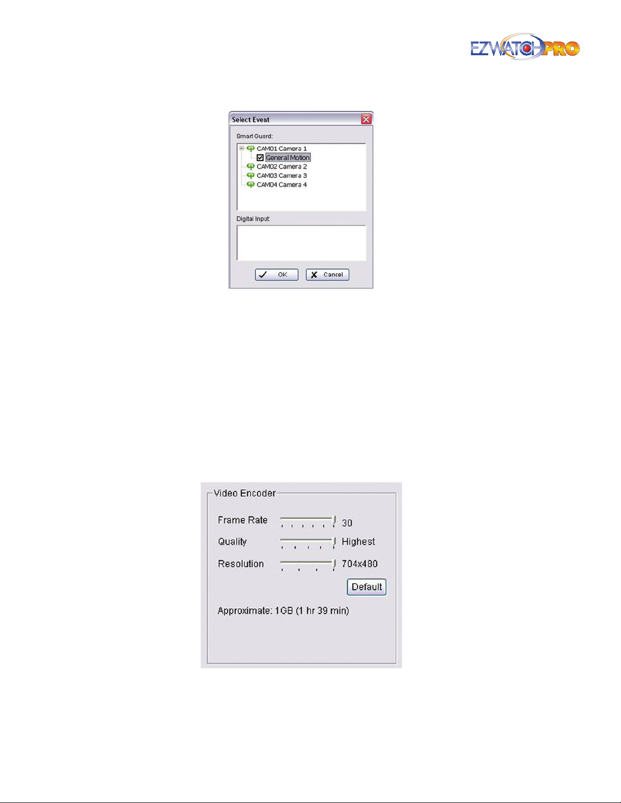
Fig. 25. Select Event window
Record On Motion Select this option to start recording when there is motion detected. To detect
motion, you have to dene a detection zone. Left-click and drag the mouse to draw a detection
zone. You may dene more than one zone on the screen by repeating the same process. User can
also click on the All button to select the entire detection zone.
Sensitivity This slider determines the amount of motion needed to activate the recording.
Frame Interval This slider determines the number of consecutive frames or motion needed to
activate the recording.
Rectangle Count When drawing your detection zone, you are limited to 10 individual rectangle
zones.
All/Clear/Default These buttons are used to select the entire detection zone, clear the detection,
and set the Sensitivity and Frame Interval back to the Default settings.
Fig. 26. Video Encoder eld set of Encoding Options
window
Frame Rate This slider allows you to adjust how many frames per second (FPS) the software will
record. The higher the frame rate, the smoother and more uid the video will be, but the le size
22 | Page Software User Manual
Page 24
of the video will be larger. The lower the frame rate, the video will appear irregular or sporadic, but
Start
the le size will be smaller. The option can vary from 1 to 30 images per second, dependent on
which grade of the software you are using (Business or Professional), as well as how many cameras
are connected.
Quality This slider aects how much compression is applied to the video. The Lowest quality will
compress the video more, creating smaller le sizes, but it will decrease the image quality.
Resolution This slider aects the amount of detail present in the image. Higher resolution
provides more detail, but simultaneously uses more disk space.
Default This will set all Video Encoder options back to the factory settings.
Approximate This text indicates how long it will take the camera to record 1GB of data if the
camera is recording constantly. As you increase the Frame Rate, Quality, and Resolution settings
the amount of time it takes to record 1GB of data will decrease. This is used as a general guide for
how long your system can record.
To estimate your total recording time, divide your hard drive size by the number of cameras you
have, and multiply that by the time in this section. For example, if you have 4 cameras and an 80GB
hard drive, and this counter states 3 hours. Your total recording would be 60 hours.
► Example 80 GB divided by 4 Cameras is 20. 20 multiplied by 3 hours is 60
hours.
If you want to extend the amount of time you are recording, then you can lower the Frame Rate,
Resolution, or Quality. You can also set your cameras to record only during certain times of the day,
or set your cameras to record only when motion is detected.
Alternatively, by installing a larger hard drive into your computer you can record more clips, and
the clips will be stored for longer periods of time. You can also install more than one hard drive to
record even longer. Consult your computer’s manufacturer for additional information.
3.2.1 Start Conguration
Fig. 27. Start button in the Main Console Conguration
menu bar
Start Menu The Start button allows you to start/stop the Recording Schedule, Smart Guard
System, and the Counting Application. Even after conguring various services within the Main
Console, such as a Recording Schedule, by default they are deactivated. You will need to start the
services here in order for them to become active.
► Note For more information on the services listed, please refer to the Table
of Contents.
Enable Secondary Display Enabling a secondary display allows you to view various features of
the software on a second monitor.
► Note For more information on using a secondary display, please refer to
3.6.10 Monitor Display Tab on Pg. 41.
Page | 23 Software User Manual
Page 25
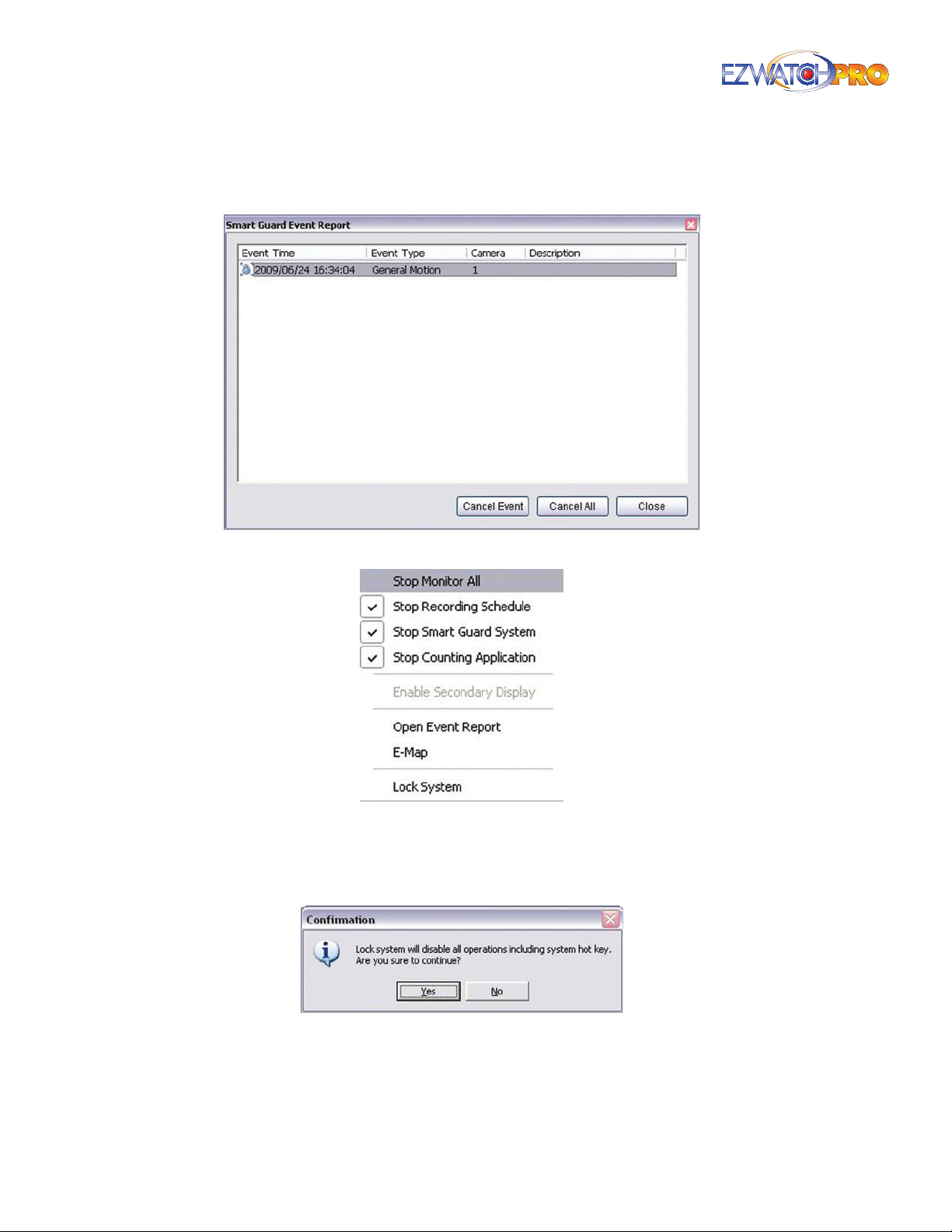
Open Event Report This option allows you to view and manually cancel a single or all currently
active Smart Guard alarms.
Fig. 28. Smart Guide Event Report window
Fig. 29. Stop Monitor All window
Lock System This feature allows you to lock the Main Console. This disables all conguration and
operation, but allows the recording schedule to resume. A username and password is required to
unlock the Main Console.
Fig. 30. Lock System Conrmation window
E-Map This feature allows you to import an overhead image map to visually show camera location
and the direction the camera is facing. You can have multiple maps, showing a large overhead
view and the ability to zoom into smaller maps. Using E-Map, a user can easily identify camera
location and respond promptly when an event occurs.
24 | Page Software User Manual
Page 26
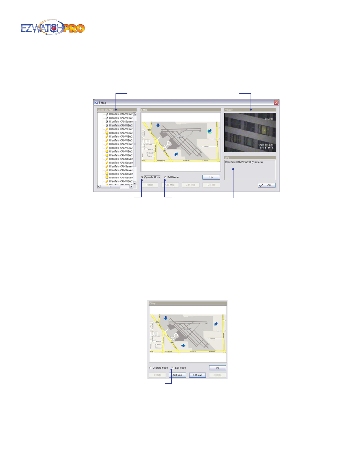
► Example In the following gure, E-Map contains an airport for the largest
map, individual maps for each terminal, and maps for each room within
the airport buildings.
PreviewDevice and Map
Operation Mode
Fig. 31. E-map window
Device and Map The list of your current devices (cameras, POS, etc.) and maps.
Operation/Edit Modes Operation mode is the active mode of the E-Map system. Edit mode allows
you to add, edit, or delete devices and maps.
Preview A preview of the selected camera’s video signal.
Info Available text information of the selected device or map.
Edit Mode
Info
3.3 Edit Mode
■ Step 1 In order to use the Edit Mode, ensure you have it selected.
Edit Mode
Fig. 32. Edit Mode of E-Map window
■ Step 2 Click on the Map icon in the Device and Map column. Once it is highlighted, click the Add
Map button.
Page | 25 Software User Manual
Page 27
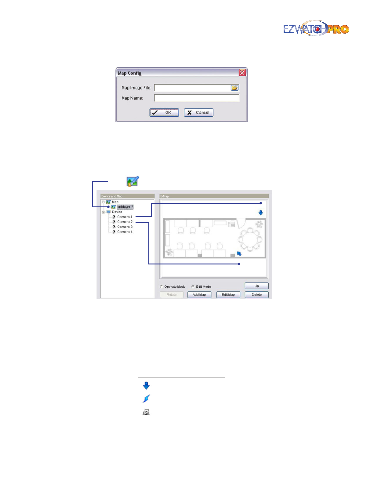
Fig. 33. Map Cong window
■ Step 3 Browse for the desired Map Image le you would like to import into E-Map. You will need
to provide your own image maps. BMP, JPEG, GIF, PNG, and TIFF images can be used. Once you
have located the map, you can also specify a Map Name.
■ Step 4 Click 'OK' and the map will appear in the Device and Map column.
Map
Fig. 34. Detail of E-Map Conguration
Edit Map This allows you to choose a dierent map and change the name of an existing map.
Delete This allows you to delete an existing map entirely.
Up This allows you to navigate up from the sub-maps to your main maps.
Once you have the devices and maps in place, you can now begin adding Device Indicators.
Device Indicators identify each individual device you are using on the map.
Camera Indicator
Digital Input Indicator
Point of Sale Indicator
Fig. 35. Device Indicators
26 | Page Software User Manual
Page 28
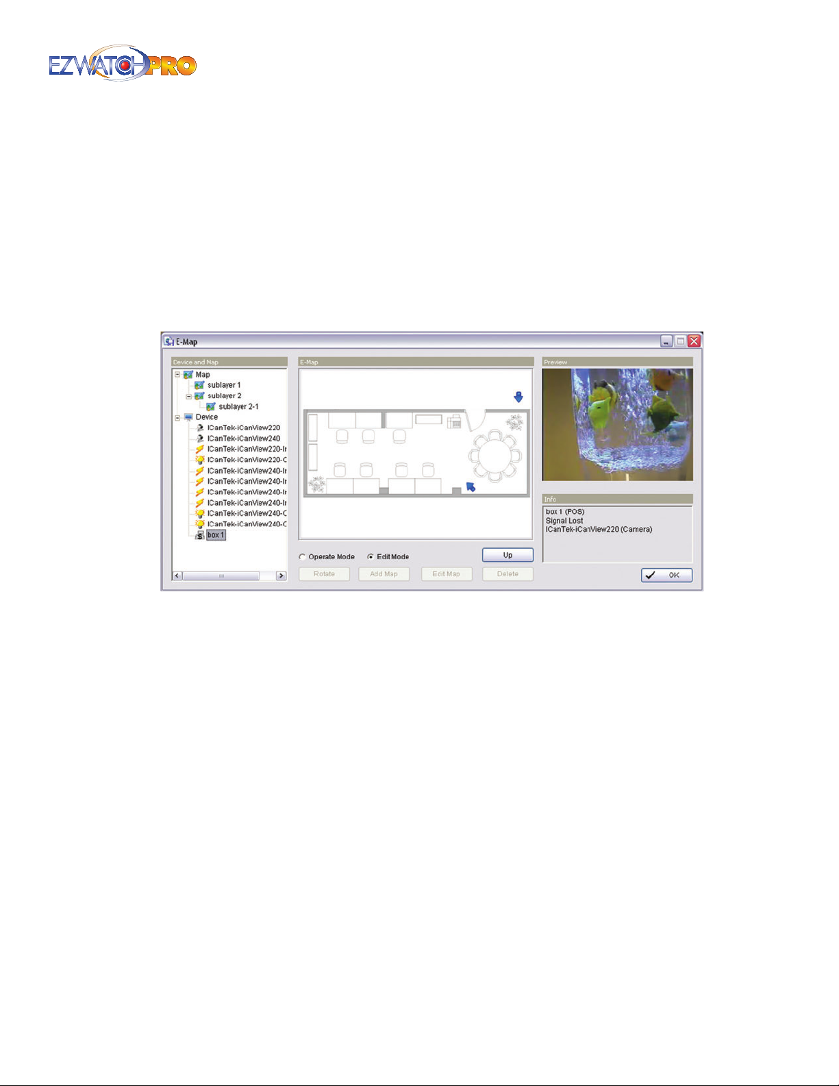
To add Device Indicators to the map, you must rst select the map in the Devices and Map column.
Once the correct map is displayed, you can left-click your devices and drag them onto the map.
■ Step 5 Once the indicator is in place, you can alter the direction by selecting the icon on the map
and click the Rotate button. The icon will rotate 45 degrees each time you click the button. This
helps identify the direction of a camera’s view.
3.4 Operation Mode
3.4.1 Device and Map Tree List
Fig. 36. E-Map window
This window will list all devices and map hierarchy. Clicking items in this list will show related
information in the panels on the right-hand side.
Map Select which map you want to show on E-Map window.
Camera Select which camera you want previewed and mark indicator on E-Map.
Digital Input Select to show indicator and status in the Info box. If the Digital Input is from an IP
camera, the preview window will display live video of the camera.
Digital Output Select to show indicator and status in the Info box. If the Digital Output is from an
IP camera, the preview window will display live video of the camera.
POS Select to show indicator and display rst associated camera’s live video.
Page | 27 Software User Manual
Page 29
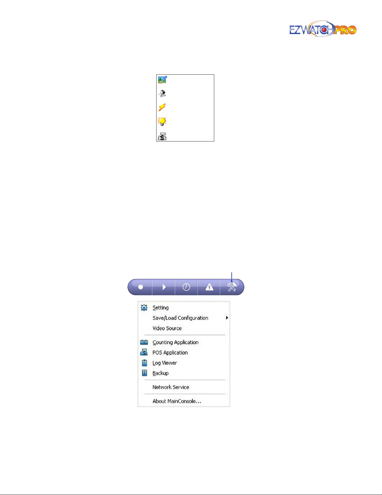
Map
Camera
Digital Input
Digital Output
Digital Output
Fig. 37. Device Indicators
3.4.2 Information and Preview Window
Map Info Show map name.
Camera Show camera name and connection status.
Digital Input Show Digital Input name and status (0 or 1).
Digital Output Show Digital Output name and status (0 or 1).
POS Show POS device name, connection status, and rst associated camera name and connection
status.
3.5 Conguration Button
Fig. 38. Conguration button
Cong
28 | Page Software User Manual
Page 30
3.6 Setting
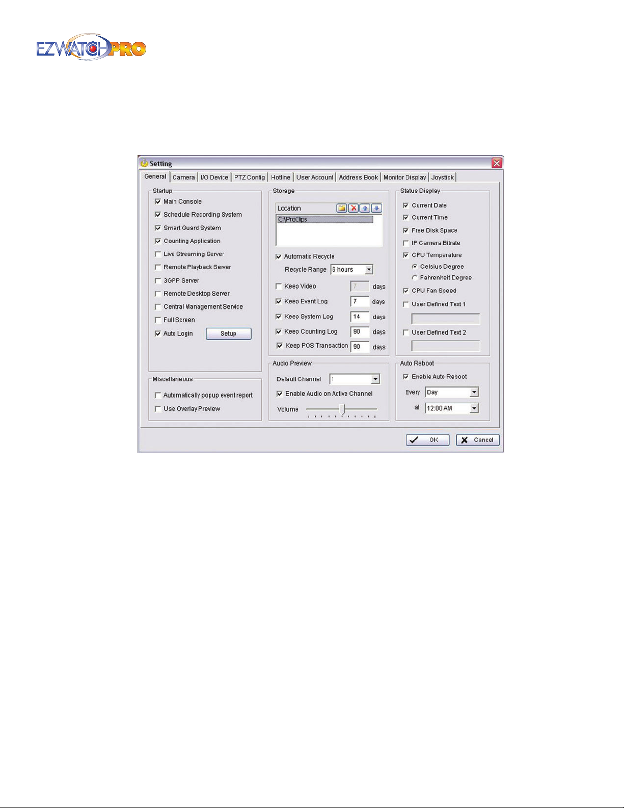
The Setting window and tabs allow you to adjust many of the Main Console options.
Fig. 39. Setting window
3.6.1 General Setting Tab
Startup Checking the boxes listed activates the functions as the Main Console starts. You may
start/stop the functions manually using the Start button from the Main Console monitor panel.
► Note For more information on the services listed, please refer to the Table
of Contents.
Auto Login Upon startup of the Main Console, you can choose to have an existing user account
automatically login.
Automatically Popup Event Report Check the box to receive popup reports when there are
events detected.
► Note Make sure to stop Smart Guard System before you modify the
setting, otherwise the modication will not take place.
User Overlay Preview (Professional Grade Cards Only) Enabling this feature will allow the chipsets
of the capture card to work with your video card to display live video, conserving CPU usage.
Page | 29 Software User Manual
Page 31
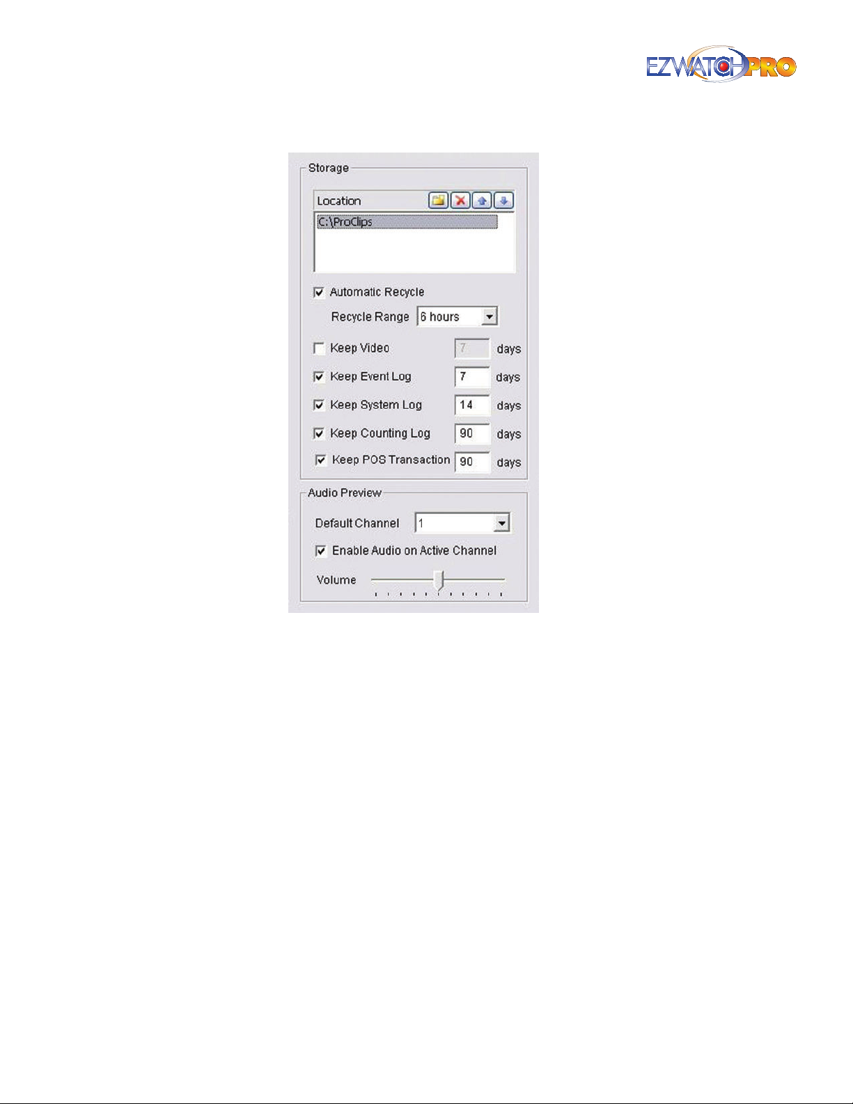
Fig. 40. Storage eld set of Setting window
Location Assign the default folder for the system to store all data les. Multiple drives can be
added to record to each one in turn, but you can only record to one folder per drive.
Automatic Recycle The system will automatically delete out-dated data to save storage space. The
'Recycle Range' tells the system how many hours of video to delete when the drive gets full.
Keep Video This will delete the video records older than the number of days set.
Keep Event Log This will delete the event log data older than the number of days set.
Keep System Log This will delete the system log data older than the number of days set.
Keep Counting Log This will delete the counting application data older than the number of days
set.
Audio Preview This is used to set up the live audio channel and adjust the sound volume.
Enable Audio on Active Channel This will allow the software to play live audio from an audio-
capable camera selected from the Main Console.
► Note For more information on the features listed, please refer to the Table
of Contents.
30 | Page Software User Manual
Page 32
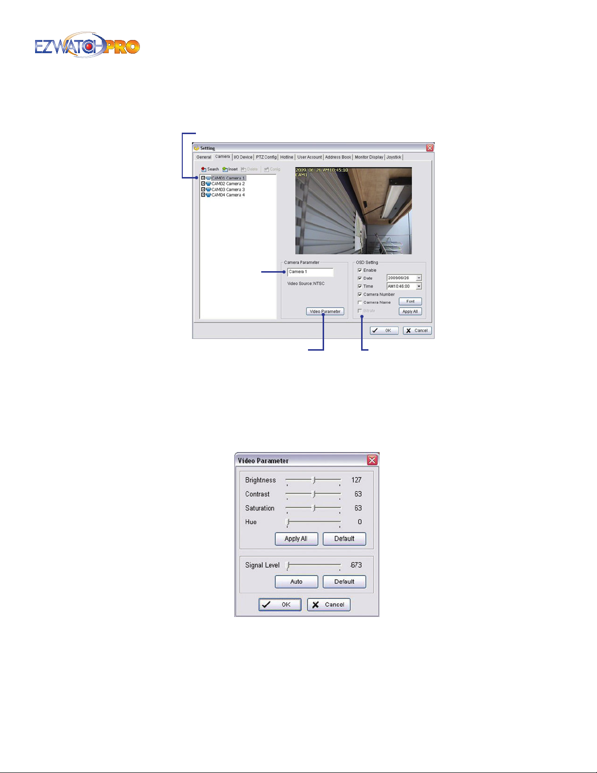
3.6.2 Camera Setting Tab
Camera List
Camera Name
Video Parameter OSD Setting
Fig. 41. Camera Settings tab
Camera List The camera(s) connected to the system will show in the panel. Click the name of the
camera to adjust the setting.
Camera Name Name the camera for your convenience.
Video Parameter Adjusts the video’s Brightness, Contrast, Saturation, Color Hue, and Signal Level.
Fig. 42. Video Parameter window
OSD Setting Select the information you want to see in the On-Screen Display (OSD), or the sub-
screen of the camera. Click the Font button to setup the font style.
Page | 31 Software User Manual
Page 33
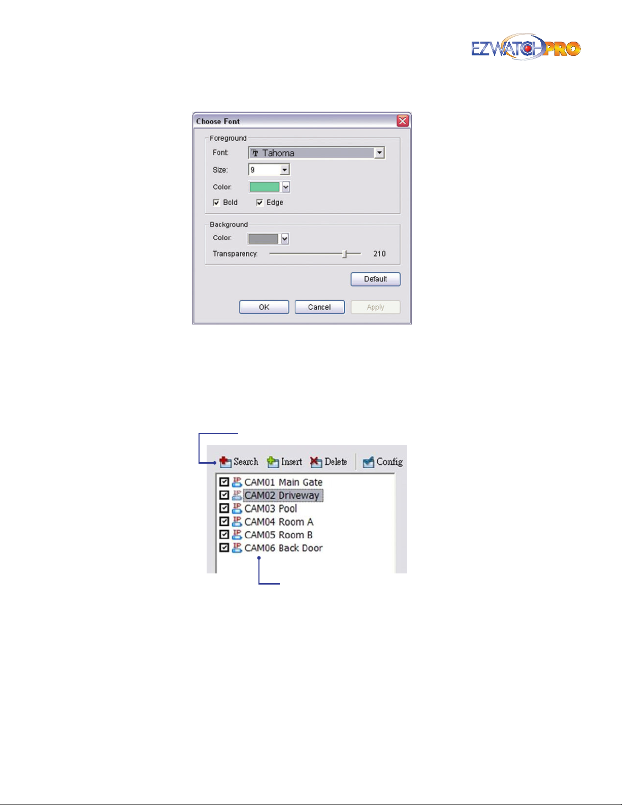
Fig. 43. Choose Font window
IP Camera Conguration
► Note This conguration is only required if you are using Internet Protocol
(IP) Cameras or adding IP Cameras to your existing analog DVR. Four
function buttons will be included in the Setting/Camera panel if you have
an IP License Dongle installed.
IP Camera Functions
Camera List
Fig. 44. IP Camera Conguration window
Search Click on the Search icon to obtain the Search IP Cameras window. The system will start
scanning automatically once the window is opened. Stop scanning by clicking on the Stop Scan
button.
32 | Page Software User Manual
Page 34
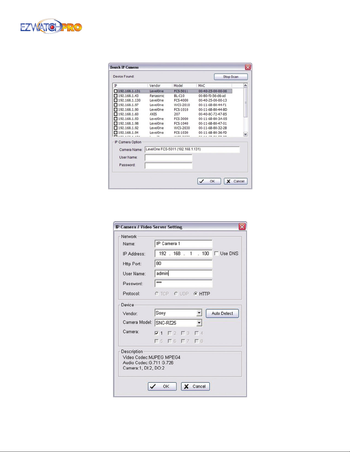
Fig. 45. Search IP Cameras window
Once cameras are found, they can be added to the Camera List by checking the box on the left and
clicking 'OK' at the bottom.
Fig. 46. IP Camera / Video Server Setting window
Page | 33 Software User Manual
Page 35
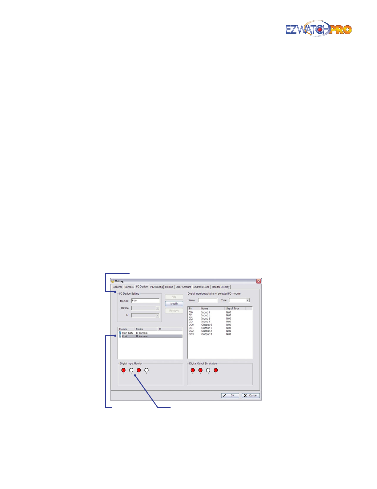
Insert Click on the Insert icon to obtain the IP/Video Server Setting window and add IP cameras to
the list. Refer to the next section for details.
Network Enter the required network information including Name, IP Address, HTTP Port, User
Name, Password, and Protocol referring to the instructions provided by the camera manufacturer.
If you connect to the camera using a domain name (Such as EZWatchIP) check the 'Use DNS' box to
type in the name instead of an IP address.
► Note For more information regarding the EZWatchIP DNS service, please
refer to 4.4 How To Set Up Internet Access Using EZWatchIP on Pg. 107.
Device You can specify the make and model of the IP camera from the option boxes here, or you
can have the software attempt to auto-detect the make and model. For auto-detect to function,
you must AT LEAST have the IP address or DNS name of the camera entered into the Network
settings.
Description Displays video codec information of the IP camera selected.
Delete Click on the Delete button to remove the selected IP camera(s) from the system. Click 'OK'
to nalize the modication.
Cong Click on the Cong button to obtain the IP/Video Server Setting panel. You can modify the
IP camera settings with the Setting window. Refer to the next section for details.
► Note Once an IP Camera is connected to the Main Console, all other
camera conguration settings similar to an Analog Camera can be
applied.
3.6.3 Input/Output (I/O) Device Conguration
Module Setting
Device List Digital Input Monitors
Fig. 47. I/O Device tab of Setting window
Module Setting Any connected I/O Modules installed will appear in this list. The 'Module' column
shows the name of the module, while the 'Device' column shows what specic module it is.
34 | Page Software User Manual
Page 36
Currently, the Main Console system supports TRP-C28 I/O modules as well as IP cameras with builtin I/O relay ports. The 'ID' is the one currently used by the module (TRP-C28), each TRP module
must have its own unique ID.
Device List This column displays the device(s) already installed to the system.
Device Setting Insert the name of the device (input and output). Select the device type from the
drop-down menu. N/O represents that the replay is open in normal condition and N/C represents
that the relay is closed in normal condition.
Input Monitor The device(s) is turned on if the dot is red. By triggering the digital input device,
the related icon will light up. This is used to check if the device is or is not correctly connected.
Output Monitor The device(s) is turned on if the dot is red. By clicking on the icon, you may
trigger the digital device connected to the system. This can be used to test if the output device is
correctly connected.
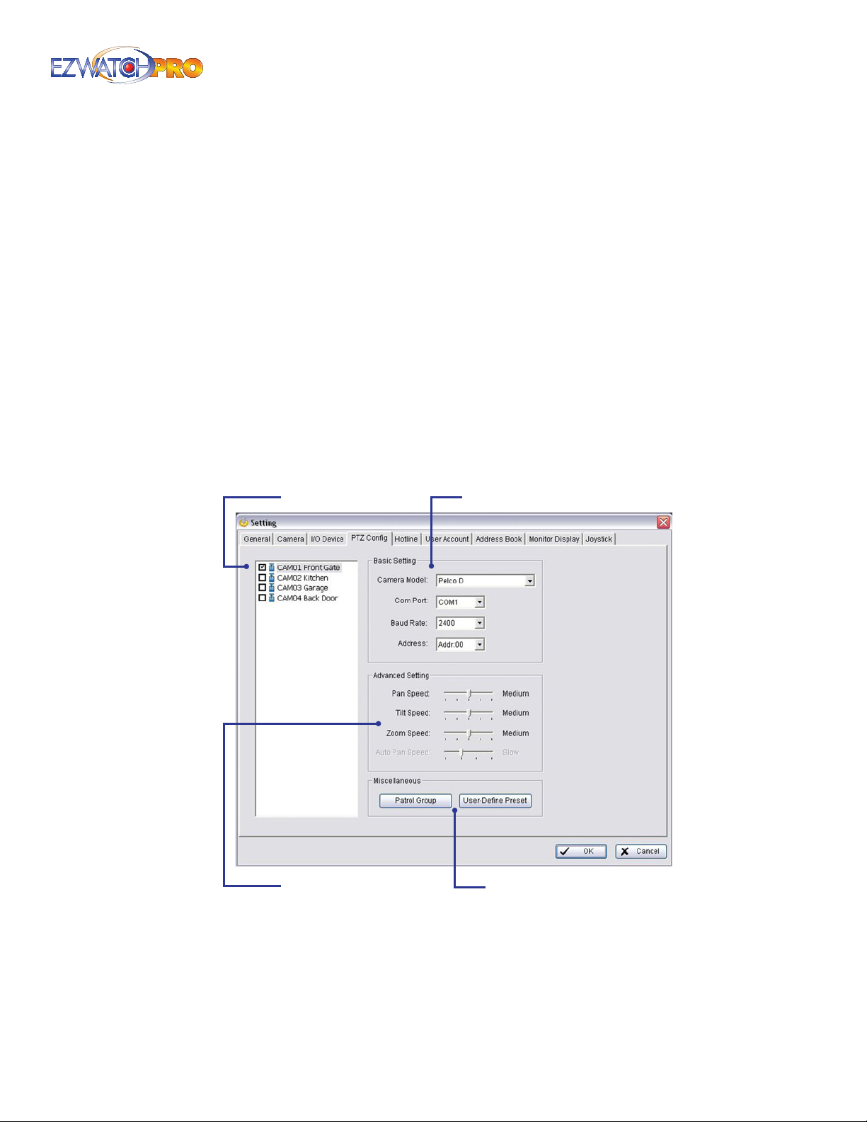
3.6.4 PTZ Conguration Tab
This window allows you to congure a Pan/Tilt/Zoom (PTZ) camera that is connected to your system
using a TRP-C08 Control Module.
Camera List Basic Setting
Advanced Setting
Fig. 48. PTZ Cong tab of Setting window
► Note For more information on connecting a PTZ Camera and Hardware
installation, please refer to 4.5 How To Set Up Pan/Tilt/Zoom Cameras
on Pg. 109.
Camera List A list of all cameras currently connected to the Main Console. Checking the PTZ
camera you want to congure will enable the setting options.
Miscellaneous
Page | 35 Software User Manual
Page 37
Basic Setting The Camera Model, Baud Rate, and Address must also match the conguration
within your camera. Refer to the User Manual of your PTZ camera for conguring the camera’s
Protocol, Baud Rate, and Address. We recommend using Pelco-P Protocol - 9600 Baud Rate, or
Pelco-D Protocol - 2400 Baud Rate.
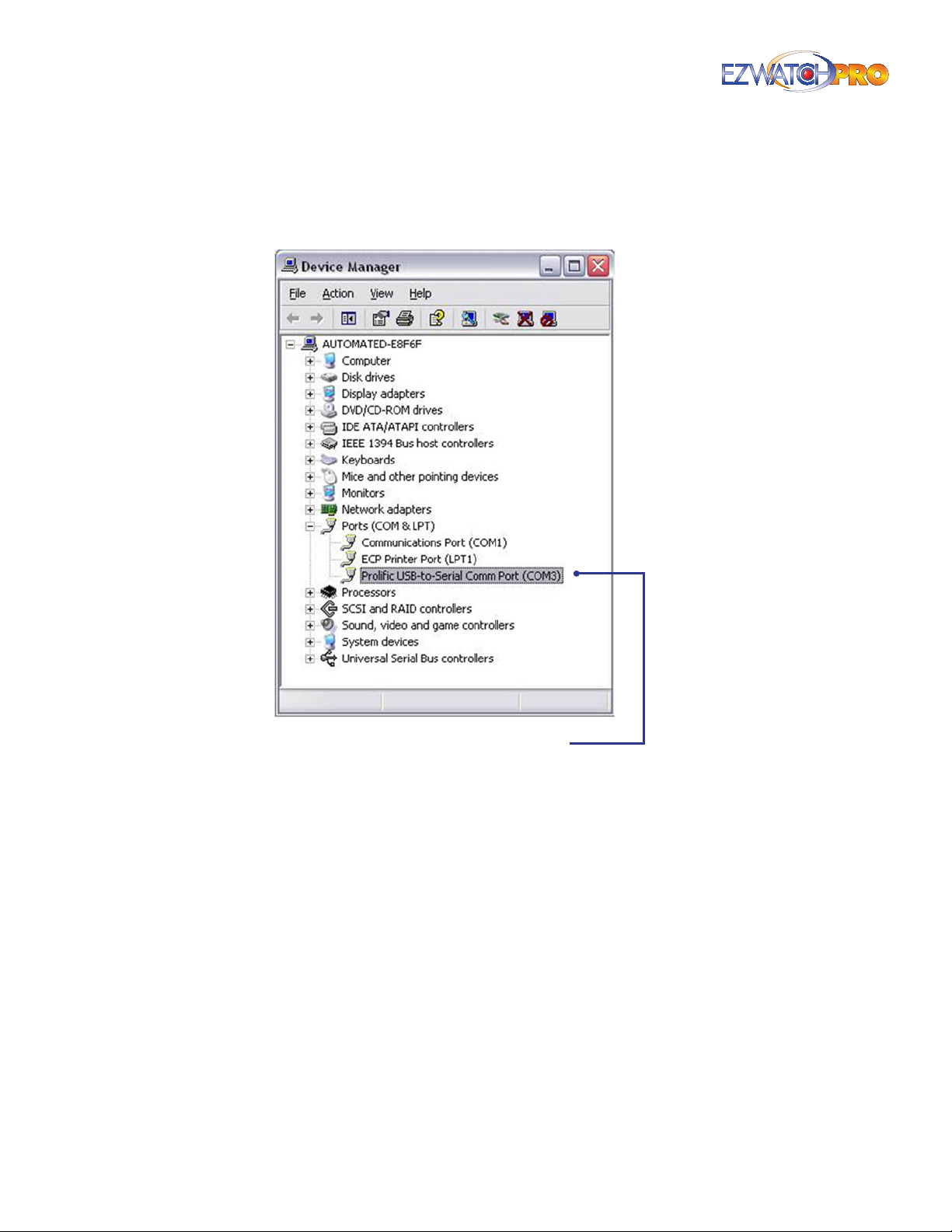
COM Port
Fig. 49. Device Manager window
The COM Port must be the port that your USB to Serial TRP-C08 is currently using. (Check the
Device Manager within Windows to verify which COM Port is being used.)
► Note If the current COM Port being used by the TRP-C08 is COM5 or above,
you will need to manually set the COM Port to COM1-COM4. Go to Port
Settings and click on the Advanced button. At the bottom of the window,
click on the drop-down button Com Port Number. Select an available
port between 1 and 4. If these ports are unavailable, contact your system
provider.
Advanced Setting You may adjust the Pan, Tilt, Zoom, and Auto Pan speeds.
Patrol Group If you have multiple pre-set positions stored within the software, this will allow you
to select a patrol where it moves between each position in the order you specify.
36 | Page Software User Manual
Page 38
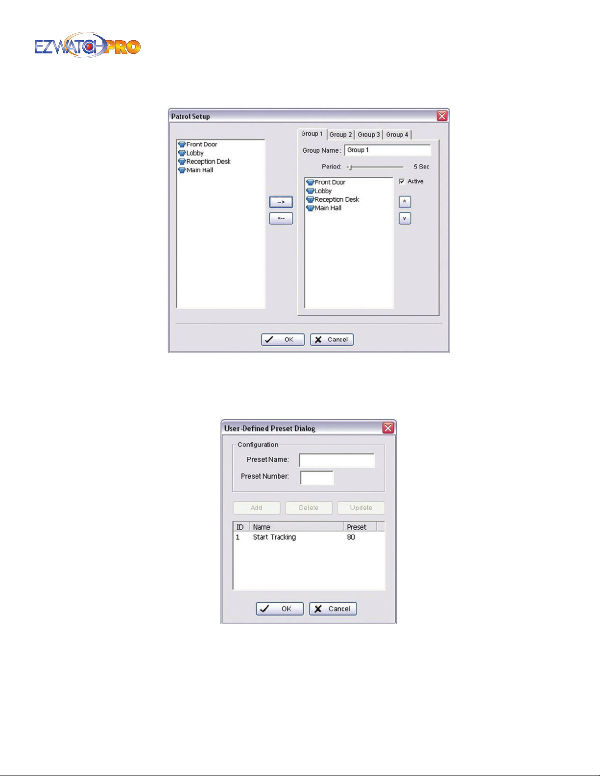
Fig. 50. Patrol Setup window
User-Dened Preset Some cameras have special features that can be activated by calling presets
above number 16. This option allows you to enter in a custom preset number. An example of this is
the EZ-TRACK PTZ camera which follows motion when you call preset 80.
Fig. 51. User-Dened Preset Dialog window
3.6.5 Main Console PTZ Control Panel
From the Main Console, left-click on the video feed of your PTZ camera. Assuming it is powered and its
address has been set correctly, you can now control the PTZ camera by utilizing the PTZ Control Panel.
Page | 37 Software User Manual
Page 39
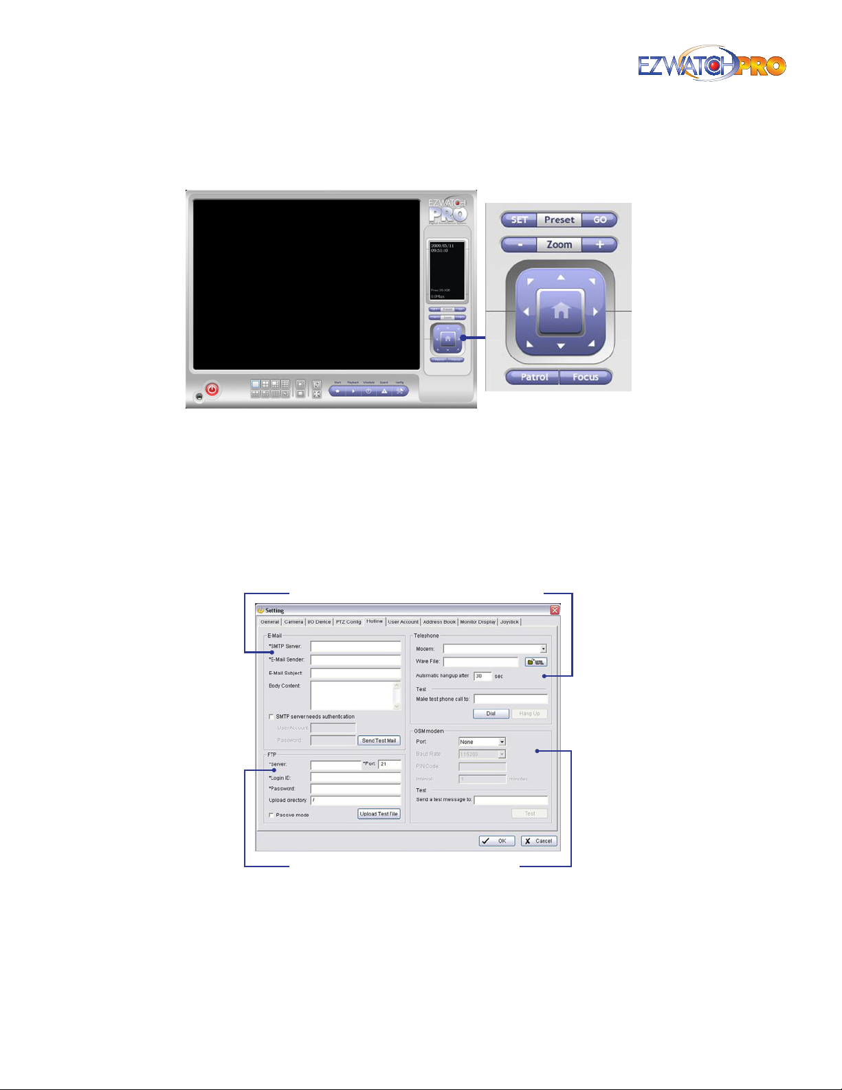
These buttons only function with PTZ cameras. The PTZ Camera control, and all buttons associated
(Presets, Zoom, Focus, Patrol, etc.) can only be selected when you left-click and highlight a PTZ camera.
Magnication
Fig. 52. PTZ Control Panel in Main Console
3.6.6 Hotline Conguration Tab
The Hotline tab allows you to congure how the server sends you alerts. Alerts are sent by the Smart
Guard system, and consist of e-mails, phone calls, text messaging, and/or remotely connecting to an
FTP server.
► Note For more information on the Smart Guard system, please refer to
3.31 Smart Guard Conguration on Pg. 74.
Email
FTP
Fig. 53. Hotline Conguration tab in Setting window
Telephone
GSM Modem
E-mail Input the following information: SMTP server, sender’s e-mail address, e-mail’s subject title,
and body content. You may click on the Send Test Mail button to test the settings. If you are unsure
of your e-mail settings, contact your e-mail provider to obtain them.
38 | Page Software User Manual
Page 40
FTP Enter the File Transfer Protocol (FTP) server and login information, as well as any initial
directory to which the system should upload screenshots.
Telephone Select the modem that the system is going to dial for the info call, and then insert the
phone number. You must have a dial-up modem installed for the system to send you a phone call
alert.
► Note You may select a Wave format audio le that will be played to alarm
the person who picks up the phone call.
GSM Modem GSM modems are cellular phones that are connected to the computer to grant
internet access via a cellular connection. By connecting your cellular phone to your computer, the
computer can send alerts via SMS messaging. If you are using a GSM modem, enter the Port, Baud
Rate, PIN Code, and Interval into these elds. If you do not have this information, please contact
your cellular phone manufacturer or network provider.
3.6.7 User Account Conguration Tab
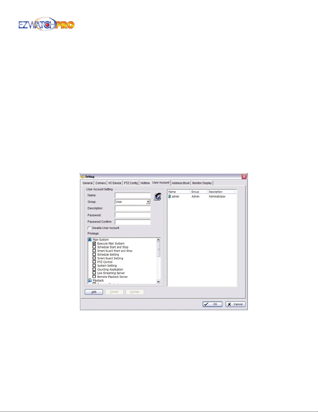
You may congure multiple users from this screen. Users are able to login locally and remotely to view
cameras. The settings allow you to restrict access and allow only certain users to perform certain tasks.
Fig. 54. User Account tab in Setting window
User Account Setting If you want to add a new user account, you will need to ll out the
Username, Password, and Password Conrm section. You may grant or deny privileges to users by
checking the privileges below. Once you have congured the allowed privileges, click on 'Add' to
add the new user account.
If you want to modify a user account, double-click on the user account you want to modify in the
right-hand pane. The login, password, and privileges currently held by that user will automatically
be lled within the Account Settings pane to the left. You may then modify the password or
Page | 39 Software User Manual
Page 41
privileges. Once you have performed all necessary modications, click on 'Update' to save your
changes.
3.6.8 Privilege
Main System This group allows you to congure whether or not a user is able to open or close the
Main Console, start or stop the recording/smart guard/remote viewing services, and control the
cameras.
Playback This group allows you to congure whether or not a user can access playback functions.
Log Viewer This group allows you to congure whether or not a user can view the system logs.
Backup This group allows you to congure whether or not a user can back up stored videos.
Remote Live Viewer This group allows you to congure which cameras a user can see when
connected and viewing the system over the internet. It also allows you to set whether or not a user
can take control of an I/O device (turn outputs on or o) or take control of the PTZ camera.
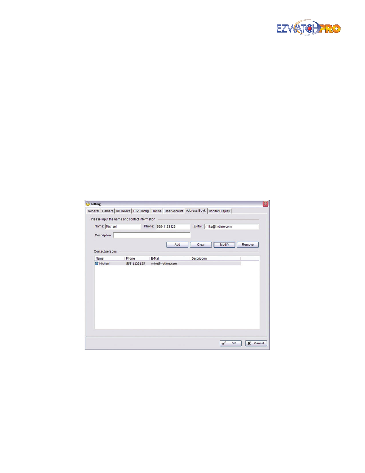
3.6.9 Address Book Tab
Fig. 55. Address Book tab in Setting window
While many Smart Guard notications are made locally, it may be necessary to notify a person who
is not on-site when an unusual event happens. For this function to succeed, you must congure a
method of contacting them using the Hotline feature, as well as specify whom to contact. This Address
Book tab allows you to specify whom to contact when an unusual event occurs. In this tab you can
specify the name of the contact, a phone number, e-mail address, and a description of the contact.
To add a new contact, type their contact information into the upper pane and click on the 'Add'
button. If you want to modify a contact you must rst double-click on their name in the lower pane.
The information about that contact will automatically be entered into the upper pane. Make whatever
changes are necessary and click on 'Modify' to save the changes.
40 | Page Software User Manual
Page 42
If you want to remove an individual contact, you must single-click on their name in the lower pane
to highlight the contact, and then click on the 'Remove' button. The 'Clear' button will remove all
information currently entered into the upper pane.
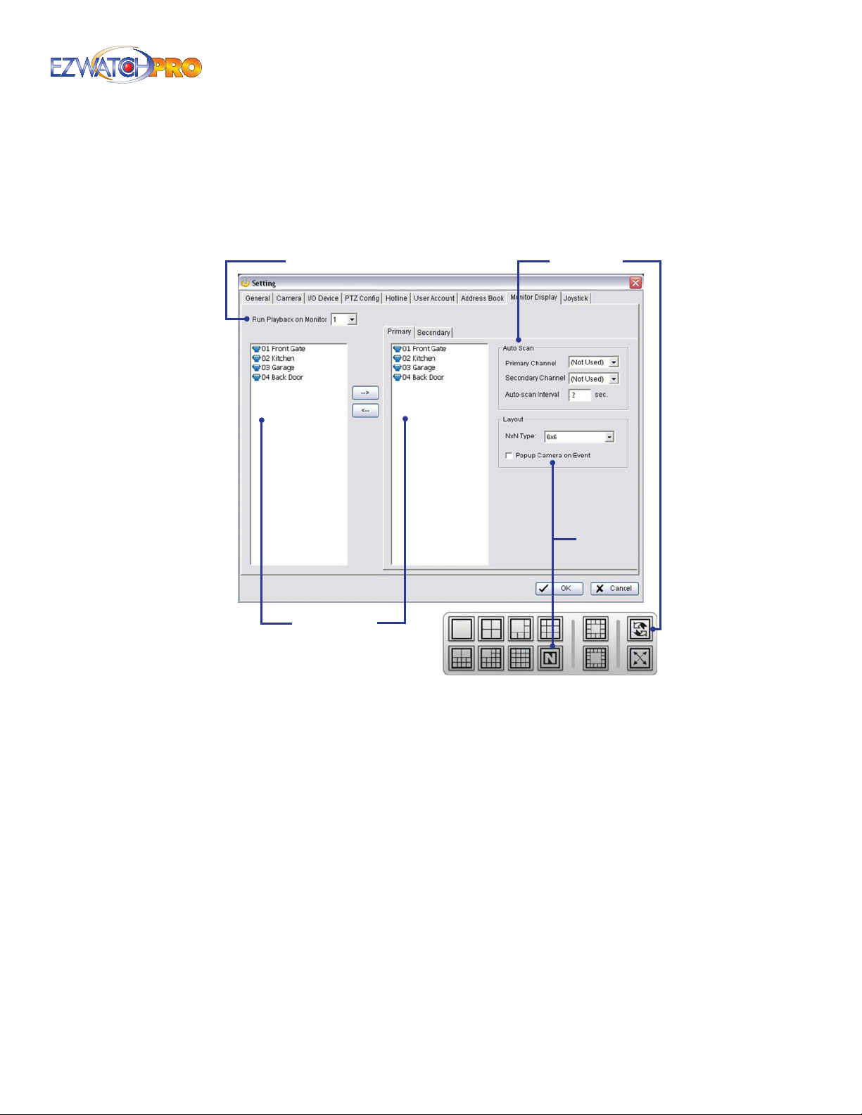
3.6.10 Monitor Display Tab
Run Playback On Monitor Auto Scan
Layout
Camera List
Fig. 56. Monitor Display tab in Setting window
Run Playback on Monitor This option allows you to select the monitor on which you want the
playback program to run. It allows you to select monitor 1, 2, or 3 when available.
Cameras List The left pane will show you a list of every camera set up on your system, while
the right pane shows you which camera can be seen on the monitor. If you have a dual-monitor
display, you will see a second tab on the screen marked 'Secondary’. When active, this allows you
to specify which cameras appear on the secondary monitor.
► Note On a Business Grade system, analog and IP-based cameras can be
seen on either monitor. On a Professional Grade system, only IP-based
cameras can appear on the secondary monitor. Analog cameras can only
be seen on the Primary Monitor.
Auto Scan This allows you to congure the Auto-Scan feature of the system.
Auto-Scan is activated by using the rotating arrows icon from the Main Console window. When
active, the computer will automatically cycle through your cameras one at a time, bringing them
up in the full screen.
Page | 41 Software User Manual
Page 43
Layout The 'N' button on the main console can display more than 16 cameras simultaneously on
the screen. The 'Layout' option allows you to congure which split screen is used when clicking the
button: 5x5, 6x6, 7x7, or even 8x8.
The 'Popup Camera on Event' box will allow the Main Console to automatically display a camera to
in the entire screen when an unusual event occurs. The event must be congured from within the
Smart Guard system to function.
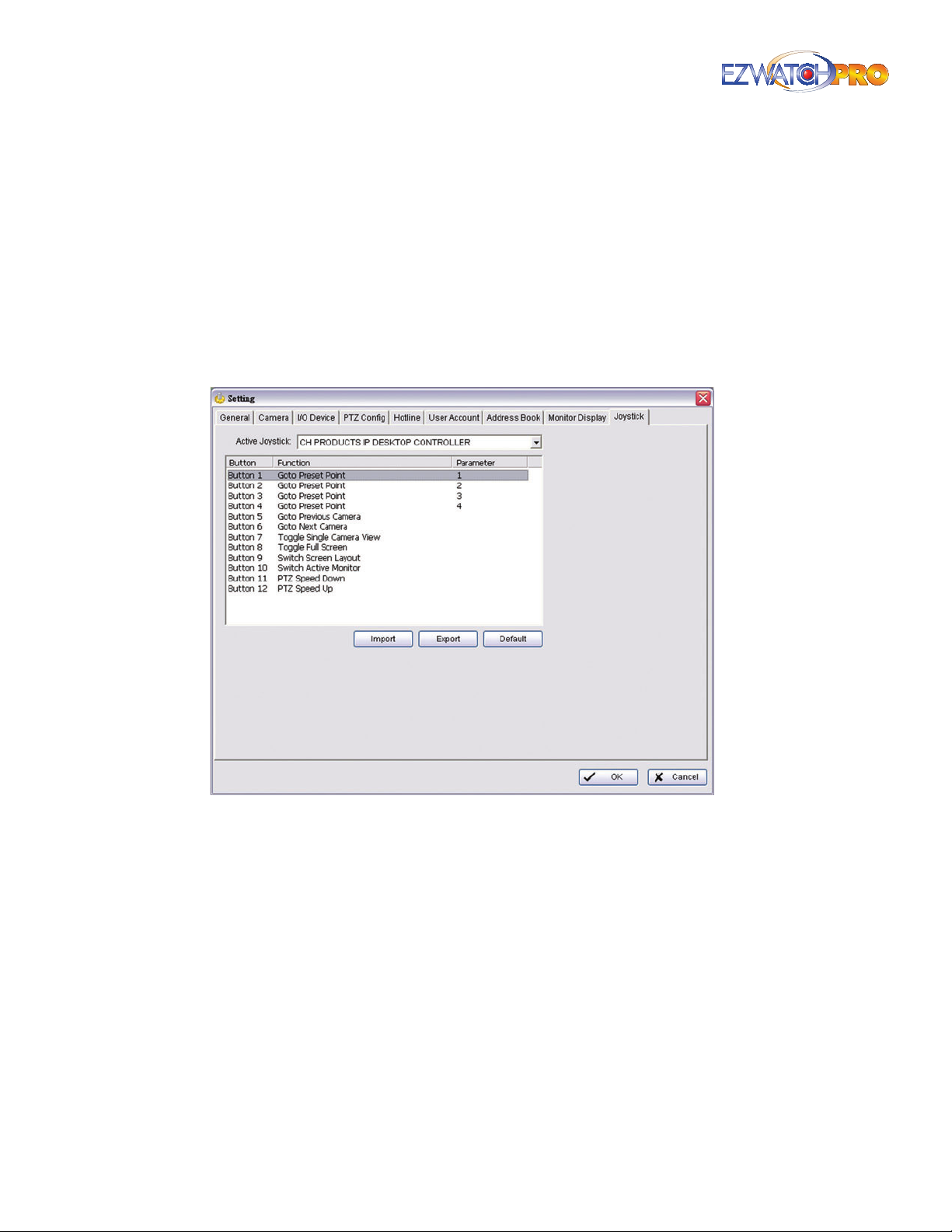
3.6.11 Joystick Tab
This feature supports the previous joystick controller used for PTZ and IP cameras. Using the TRP-C08
module, this conguration is no longer necessary for current joystick controllers.
Fig. 57. Joystick tab in Setting window
Function You can choose the function from the drop-down menu for the Joystick tab.
Following is a complete list of all log types:
1. N/A
2. Goto Preset Point
3. Goto Camera
4. Goto Previous Camera
5. Goto Next Camera
6. Switch Screen Layout
7. Toggle Single Camera View
42 | Page Software User Manual
Page 44
8. Toggle Full Screen
9. Start/Stop Auto Scan
10. PTZ Speed Up
11. PTZ Speed Down
12. Zoom Wide
13. Zoom Tele
14. Start/Stop Patrol
15. Switch Active Monitor
Parameter You can choose the parameter of the function from the drop-down menu.
Default You can set the default setting for the joystick.
Export You can export the setting of the joystick.
Import You can import the setting of the joystick.
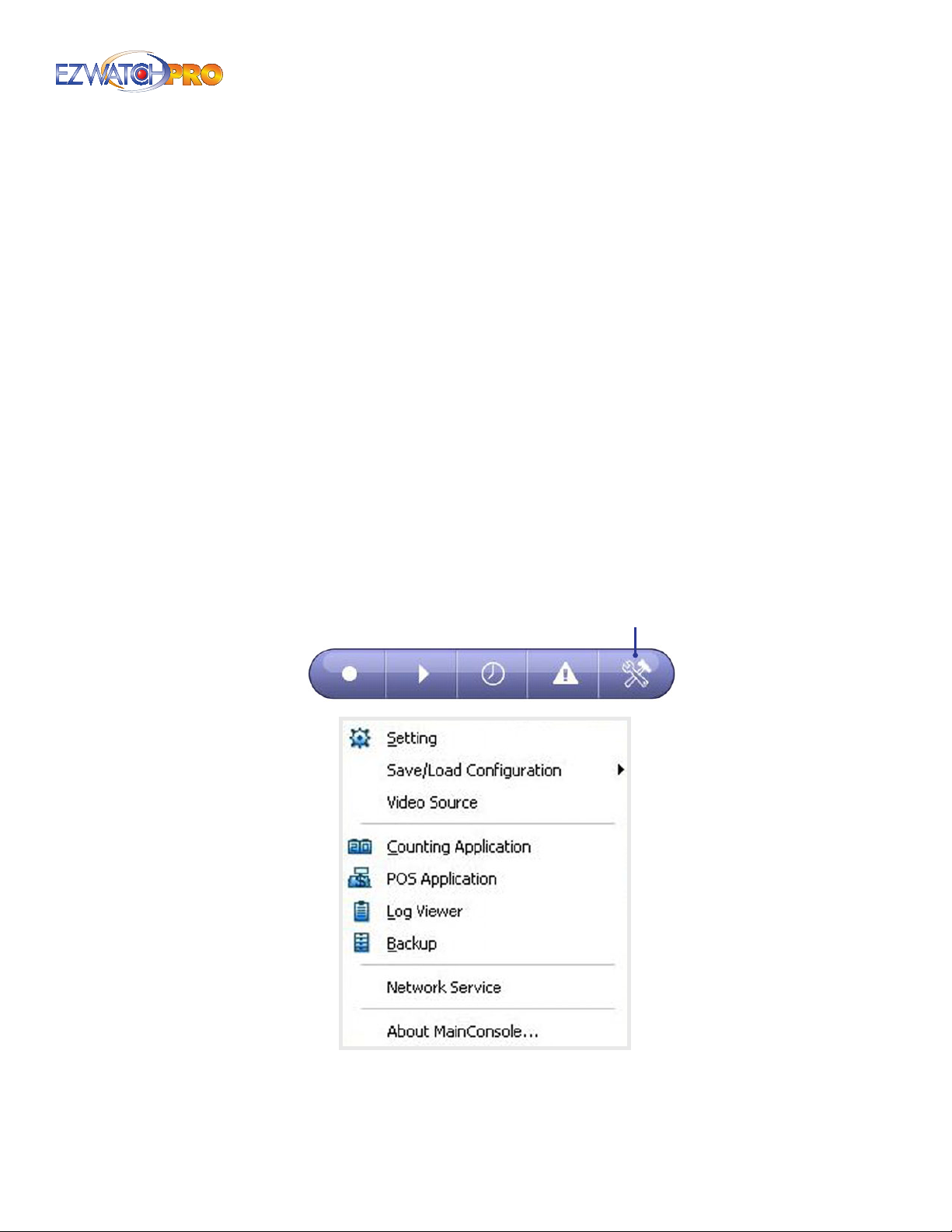
3.7 Additional Conguration Menu Options
Cong
Fig. 58. Conguration button and Conguration menu
options
Page | 43 Software User Manual
Page 45
3.7.1 Save/Load Conguration
The Save/Load Conguration function allows system users to save any specic setting as a cfg (cong)
le. You may save several dierent cfg les at any time.
Save Conguration To save a specic setting, go to Cong > Save/Load Conguration > Save. In
the popup window, type in the le name and then save it as a cfg le.
Load Conguration To load a specic setting, go to Cong > Save/Load Conguration > Load. In
the popup window, go to the directory in which you saved the cfg les, select the desired cong
le and then click OK to load the le.
► Note This feature is very useful in the event you need to uninstall and
reinstall the Main Console software. It is recommended that you save your
conguration settings regularly.
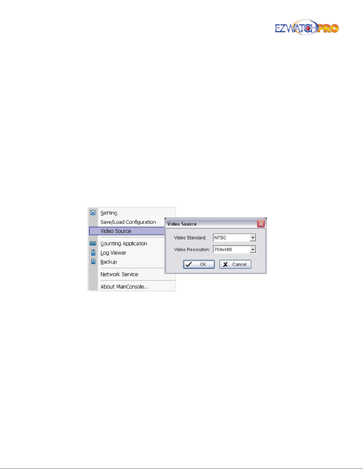
3.7.2 Video Source (Business Grade Only)
This setting allows you to adjust the Video Standard (NTSC or PAL) and adjust the maximum Video
Resolution for all analog cameras. It is recommended that you increase the resolution in order to
record higher than the default resolution of 352 x 240.
Fig. 59. Video Source window
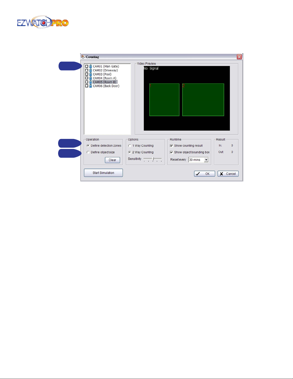
3.7.3 Counting Application
The counting application will allow you to track movement between two areas of the screen. This can
be used to count the number of people passing through a doorway, the number of objects moving
along a conveyor, etc.
44 | Page Software User Manual
Page 46
Step 1
Step 2
Step 3
Fig. 60. Counting Application window
■ Step 1 Select camera on which you want to count passing objects.
■ Step 2 In Operation elds set, dene the detection zone. Drag the cursor to draw Region 1 and
Region 2. The two regions MUST be directly next to each other. Objects moving from Region 1 to
Region 2 are counted as moving 'In’. Objects moving from Region 2 to Region 1 are counted as
moving Out (2-way counting only).
■ Step 3 Dene the object size on the screen. Objects about this size will be counted while
traversing these two regions. Objects that are larger than the detection zones will not be counted.
If you want to track large objects make certain the detection zone is large enough to contain the
entire object.
Options Allows you to count trac in one direction (In only. Objects moving from Region 1 to
2) or in both directions (In and Out. Outbound trac consists of objects moving from Region 2
to Region 1).
Runtime Show Counting Result will display the camera count in the camera window on the
Main Console. Show Object Bounding Box will display the size of the object on the screen.
Start Simulation Click to test the setting.
Once you have entered in the Counting application settings, please make certain the counting
application is running for it to function. You can start the Counting application manually by
clicking 'Start' then 'Start Counting Application' from the Main Console window.
Page | 45 Software User Manual
Page 47
3.7.4 POS Application
Each Main Console system can manage up to 64 POS cash register devices. The POS Application tool is
used to help congure POS devices. Please refer to the User manual of POS for details. Please contact
EZ Watch Pro Support at 1-866-241-3400 for additional information.
Step 2
Step 1
Step 3 Step 4
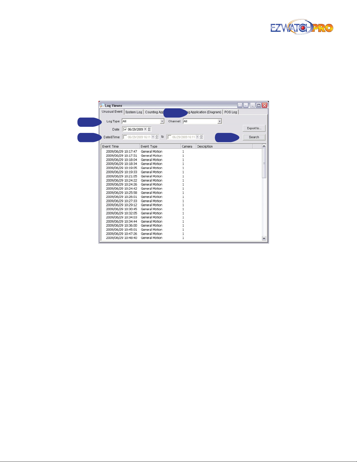
Fig. 61. Log Viewer window
Log Viewer The log viewer keeps a record of special events that occur within the system. Events
can consist of Smart Guard alerts, System alerts, and attempts to log in or out both locally and
remotely.
Unusual Event Tab Display a log history of when any unusual events were triggered by the Smart
Guard system. The system will only record events that are set to trigger a Smart Guard alert.
■ Step 1 Choose the type of event you want to check or select 'All' from the drop-down menu for
all types of events.
■ Step 2 Select the camera you want to check the event(s) from or select 'All' for all available
channels.
■ Step 3 Select a search period. For a specic date, check the 'Date' box right and indicate the date.
For a period, check the Date & Time box and enter the date and time.
■ Step 4 Click Search to display the results.
► Note For more information on the Smart Guard system, please refer to
3.31 Smart Guard Conguration on Pg. 74.
46 | Page Software User Manual
Page 48
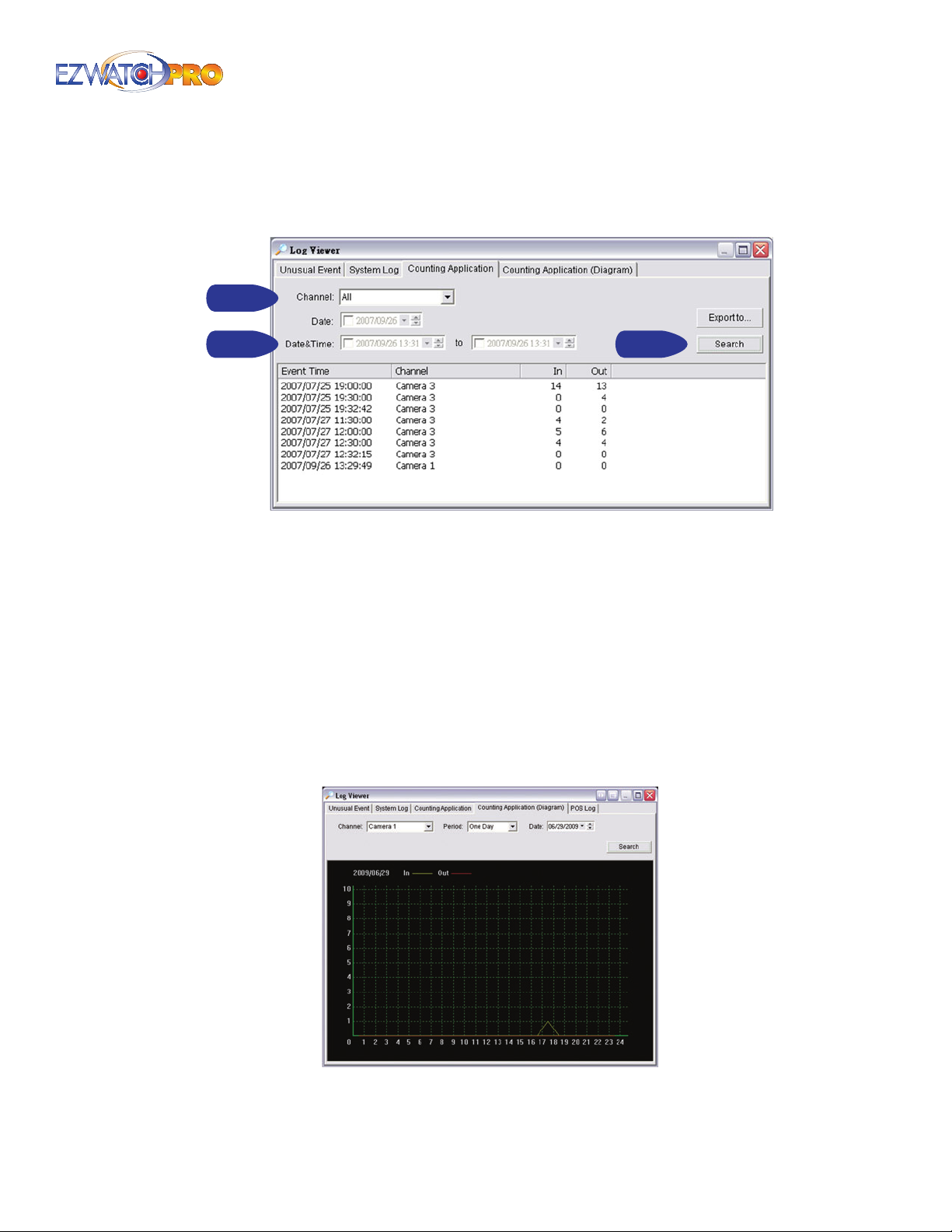
3.8 Counting Application Tab
Display a log history of the Counting Application in a specied time period.
Step 1
Step 2
Fig. 62. Counting Application log history for a specied
period of time
Step 3
■ Step 1 Select the channel you want to check or select 'All' from the drop-down menu for all
channels.
■ Step 2 Select a search period. For a specic date, check the 'Date' box right and indicate the date.
For a period, check the Date & Time box and enter the date and time.
■ Step 3 Click Search to display the results.
3.9 Counting Application (Diagram) Tab
This will show you a graph of the inbound and outbound trac recorded by the Counting Application.
Follow the same steps above to search through a period to display.
Fig. 63. Counting Application (Diagram)
Page | 47 Software User Manual
Page 49
3.10 Point Of Sale (POS) Log
View the POS Log history that has been detected by the Smart Guard System, include Transaction
Start, Transaction End, Open Cash Register, Connection Lost, and special User Dened events. The POS
Log is used to help monitor POS devices. Please refer to the User manual of POS for details. Please
contact EZ Watch Pro Support at 1-866-241-3400 for additional information.
3.11 Backup System
The Backup function allows you save video clips and system logs. It will create a copy of the playback
system, which can be used on any computer running Microsoft Windows XP (or later variants).
Step 1
Fig. 64. Backup System window
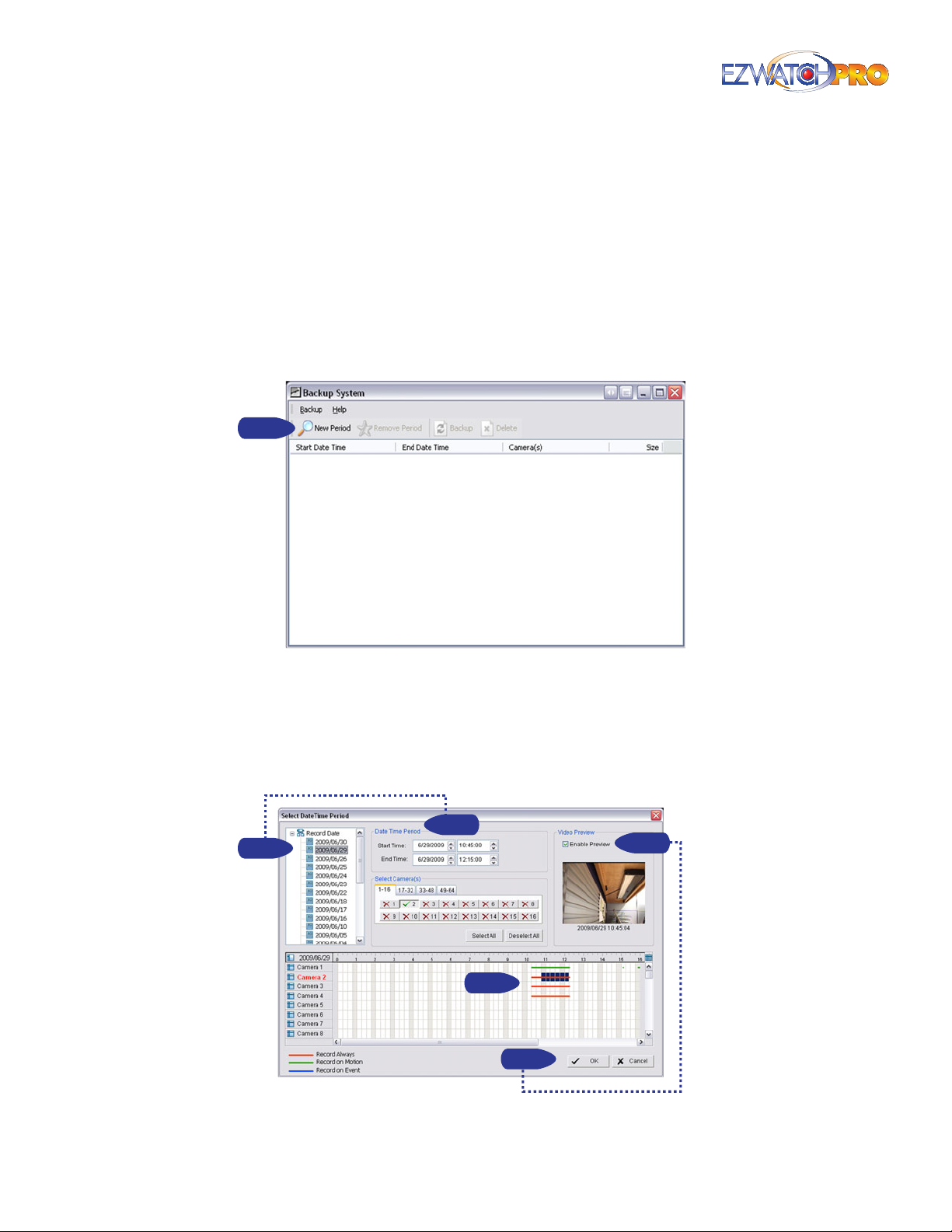
■ Step 1 Click on 'New Period' to obtain the Select DateTime Period window.
■ Step 2 From the record date section, select the date you want to backup from. You will see color
lines appear in the Time Table implying available data recorded. Red, green, and blue represent
record always, record on motion, and record on event data les, respectively.
Step 2
Step 2
Step 3
Step 4
Step 4
Fig. 65. Select DateTime Period window
48 | Page Software User Manual
Page 50
■ Step 3 Select the data you want to backup by highlighting the time period. You can also
highlight data automatically by selecting a start and end time at the top of the window, and
selecting which cameras to back up just below the date/time period.
■ Step 4 Check the box 'Enable Preview' for a preview of the video you selected. Only the rst
camera you select will be displayed. Once you have the desired video les selected, click 'OK' to
return to the Backup window.
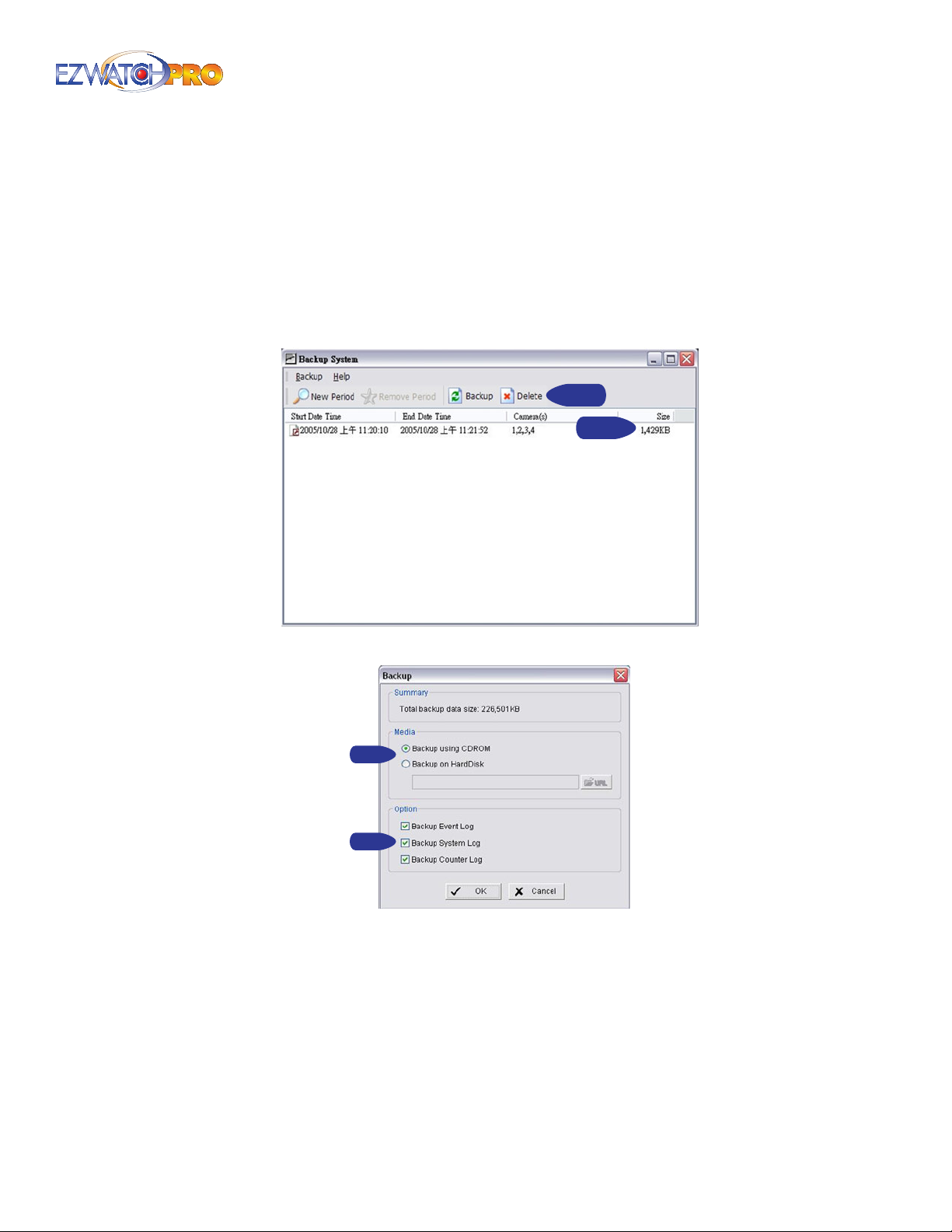
■ Step 5 The size of the selected period is displayed on the right-hand side of the window. You can
select to 'Backup' the period, or 'Delete' it by using the options at the top of the window.
Step 5
Step 5
Fig. 66. Backup System window
Step 6
Step 7
Fig. 67. Backup window
■ Step 6 Choose whether you want to backup the les to a CD-ROM (requires Windows XP) or to a
folder on your hard disk. If you choose to back up the video to the hard disk, you will need to type
in the location in which to save the backup, or click the 'URL' button and browse to the desired
location.
■ Step 7 If you want to backup event, system, or counting application logs, you must select them
here. Once you have nished, press 'OK' to begin the backup.
Page | 49 Software User Manual
Page 51
3.12 Deleting Recorded Video and Information
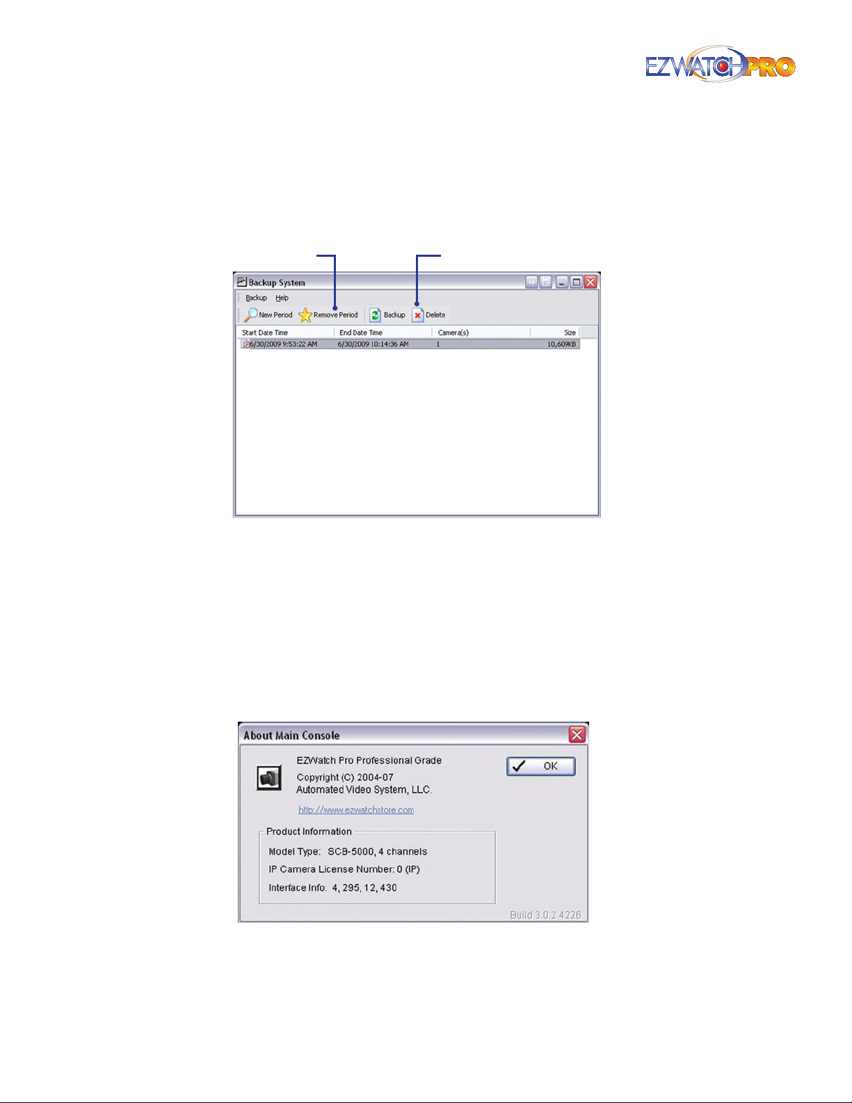
Follow steps 1-5 in the previous section to select a period. Once your period has been selected, you
can use the 'Delete' icon instead of the 'Backup' icon to remove the unwanted video clips and system
logs.
Remove Period
Fig. 68. Backup System window
Remove Period This option simply removes the selected search result from the list. It does not
delete it from the system.
► Warning Deleted clips are NOT recoverable. If you do not want to lose
data it is recommended you back up the period before deleting it.
Delete
3.13 About Main Console
Go to About Main Console to view the version of your surveillance system and the hardware
information.
Fig. 69. About Main Console window
If you are using an EZ Watch Pro Business Grade or Professional Grade system, you will see the model
type of your video capture card present on this screen.
50 | Page Software User Manual
Page 52
If you have an IP camera license, you will see the number of licenses you are currently using.
The build number in the lower right will indicate what version of software your system is currently
running. Press 'OK' to exit the About Main Console window.
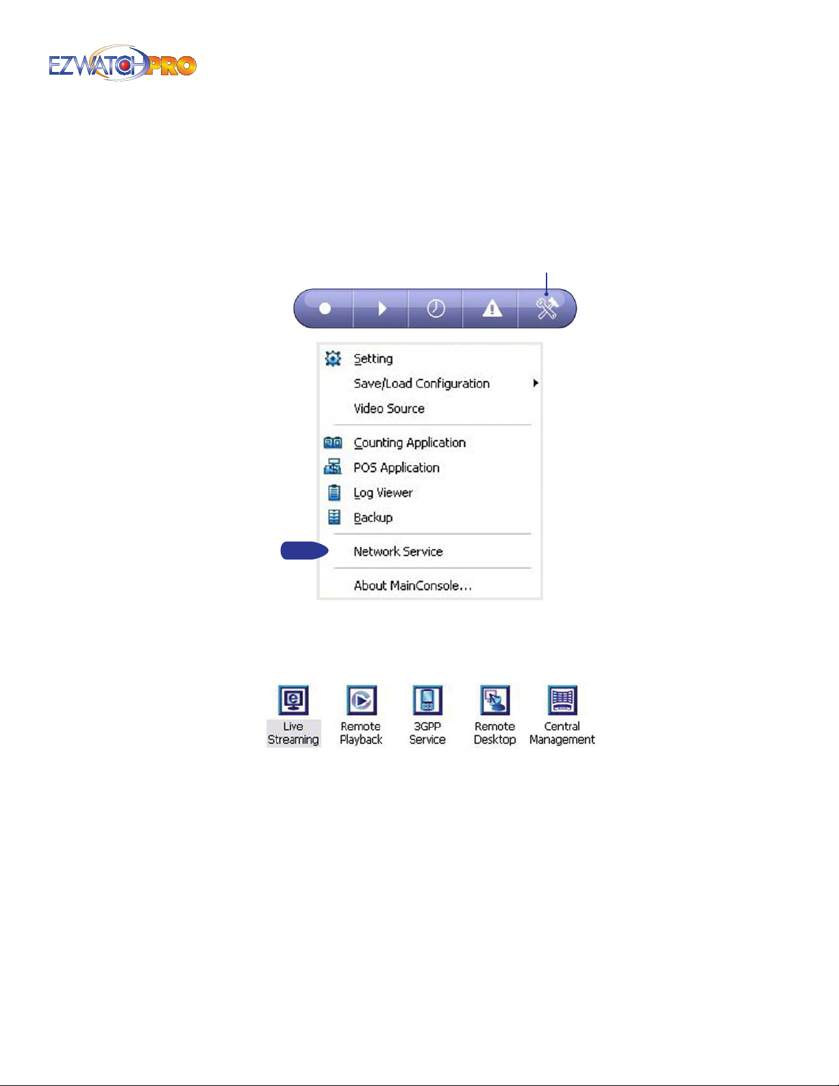
3.14 Network Service Conguration
Cong
Fig. 70. Network Service selection in Conguration menu
The Network Service feature allows you to enable and congure servers within the Main Console. This
will allow Remote Access through a network connection. There are ve available Network Services.
Fig. 71. Icons for the 5 Network Services
Live Streaming This service controls the ability of a remote user to connect and view a live image
from the camera system.
Remote Playback This service controls the ability of a remote user to connect and playback
previously recorded video clips.
3GPP Service This service controls the ability of a remote user to connect and view video images
using a Cell Phone or other compatible 3GPP device.
Remote Desktop This service controls the ability of a remote user to connect and take control of
the DVR and be able to make changes to it as if the remote user was sitting directly in front of the
DVR.
Page | 51 Software User Manual
Page 53
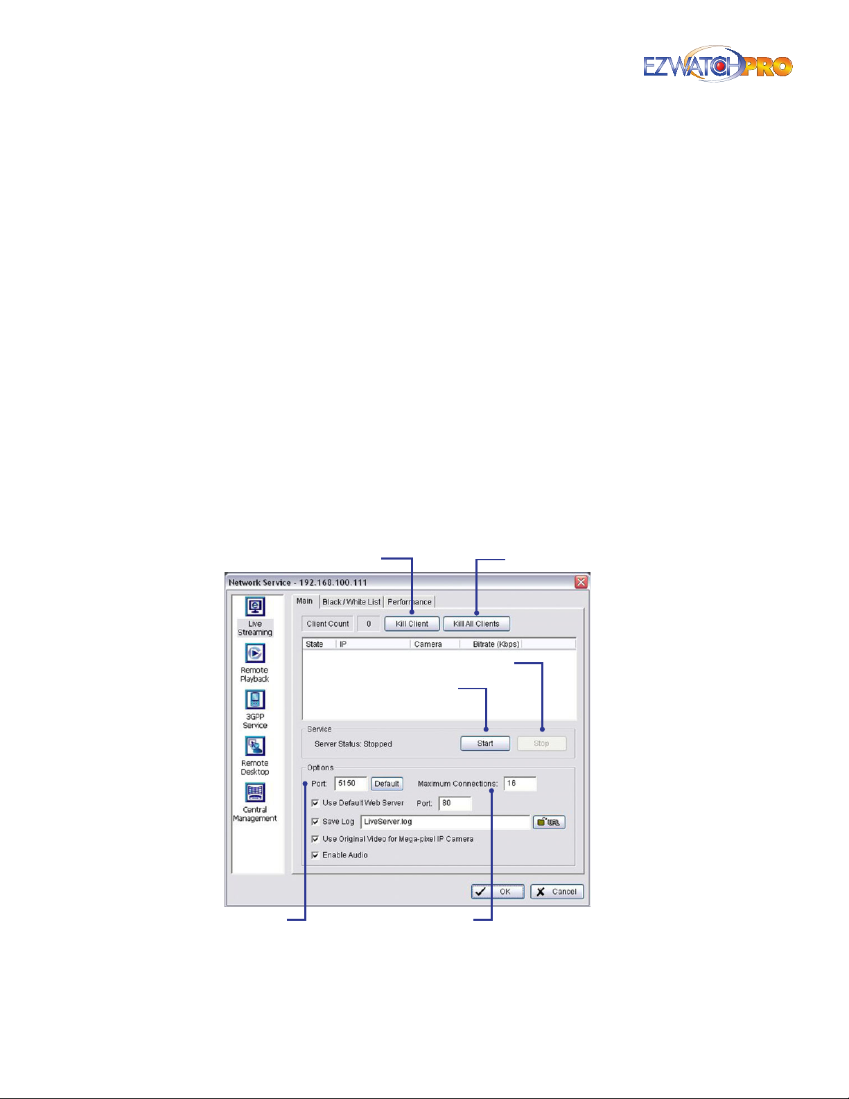
Central Management This is a unique service which allows you to tie in multiple camera systems
to a single location. All cameras from all DVRs can be seen and alerts can be congured to pop up
from multiple locations.
► Note The Central Management system is not included by default with the
EZ Watch Pro kits and software. Using this feature will require additional
software and licensing. Please contact EZ Watch Pro sales at 1-866-2413400 for pricing and availability.
► Warning We recommended conguring your Network Service features
before attempting to connect from a remote location. For more
information on Remote Viewing and Playback using the Network Service
features, please refer to 3.40 Remote Access Conguration on Pg. 90.
3.15 Live Streaming Server
The live streaming server is the service which controls a remote user’s ability to connect and view a live
image from the video cameras. A system administrator can congure the service to limit the number
of concurrent connections, to ban people from viewing the cameras live, or to restrict access to only a
few users.
3.15.1 Main Tab
The Main tab allows you to see how many users are currently connected, how many cameras are being
viewed, and allows you to congure the connection options.
Stop
Start
Port
Fig. 72. Main tab in Network Service window
Maximum Connections
Kill All ClientsKill Client
Kill Client If you want to disconnect a single connection, click and highlight it in the list and click
the 'Kill Client' button.
52 | Page Software User Manual
Page 54
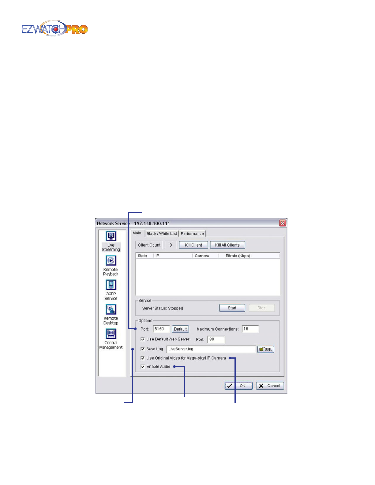
Kill All Clients If you want to disconnect ALL connections to your system, click this button.
Start Before users can connect, the service must be started. If the server status indicates 'Running’,
the service is currently active.
Stop Click this to turn o the remote live viewer server. If the server status indicates 'Stopped’, then
the service is already turned o.
Options You may only adjust the Option settings when the server is stopped.
Port Assign a port for the clients to connect to your system through the network. The default port
is 5150.
Maximum Connections Each camera a user views counts as a single connection. If you want
to restrict the number of people connected, you can limit the number of connections here. The
default setting is a maximum of 16 connections.
► Example 4 people viewing 4 cameras, 2 people viewing 8 cameras, or a
single person viewing 16 cameras all count as 16 connections.
Save Log This allows you to specify the name of the log le and the location it is stored on the PC.
Use Default Web Server
Save Log
Fig. 73. Main tab in Network Service window
Enable Audio
Use Original Video
for Mega-pixel IP Camera
Page | 53 Software User Manual
Page 55
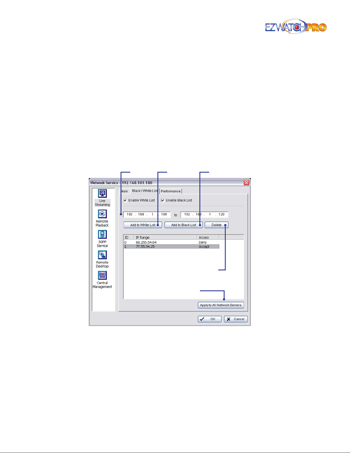
Use Original Video for Megapixel IP Camera Check this box for original megapixel resolution.
Otherwise, the resolution will be compressed for better transmitting quality purpose.
Use Default Web Server If you want to view the cameras using an Internet Explorer web browser,
you will need to check this box. If this box is not checked then you can only connect using the
Remote Live Viewer software from the installation CD. The default web port is 80.
► Note If you change the web port to anything other than 80, then you must
place the port at the end of the web address. For example, if your web
address is normally http://username.ezwatchip.com/ and you change
the web port to 8000, you would connect by typing in http://username.
ezwatchip.com:8000/.
Enable Audio This feature enables streaming of live audio.
3.15.2 Black/White List Tab
IP Field
White List
Black List
Add/Delete
Apply to All Playback Servers
Fig. 74. Black/White List tab in Network Service window
White List The 'White List' is a list of addresses that are authorized to connect and view the
cameras. If this option is checked, then ONLY addresses on the list can connect, and any address
not currently on the list will be blocked. This is useful for restricting access to a small group of
addresses, such as a local network.
► Note This option can frequently cause connection problems if congured
incorrectly. If you are having any problems connecting and viewing
cameras, it is highly recommended that you uncheck this option.
Black List Check the 'Enable Black List' box to activate the black list lter. If this option is checked,
anyone can connect EXCEPT the addresses on this list. This is ideal for blocking a specic address,
such as a terminated employee, from viewing the cameras.
54 | Page Software User Manual
Page 56
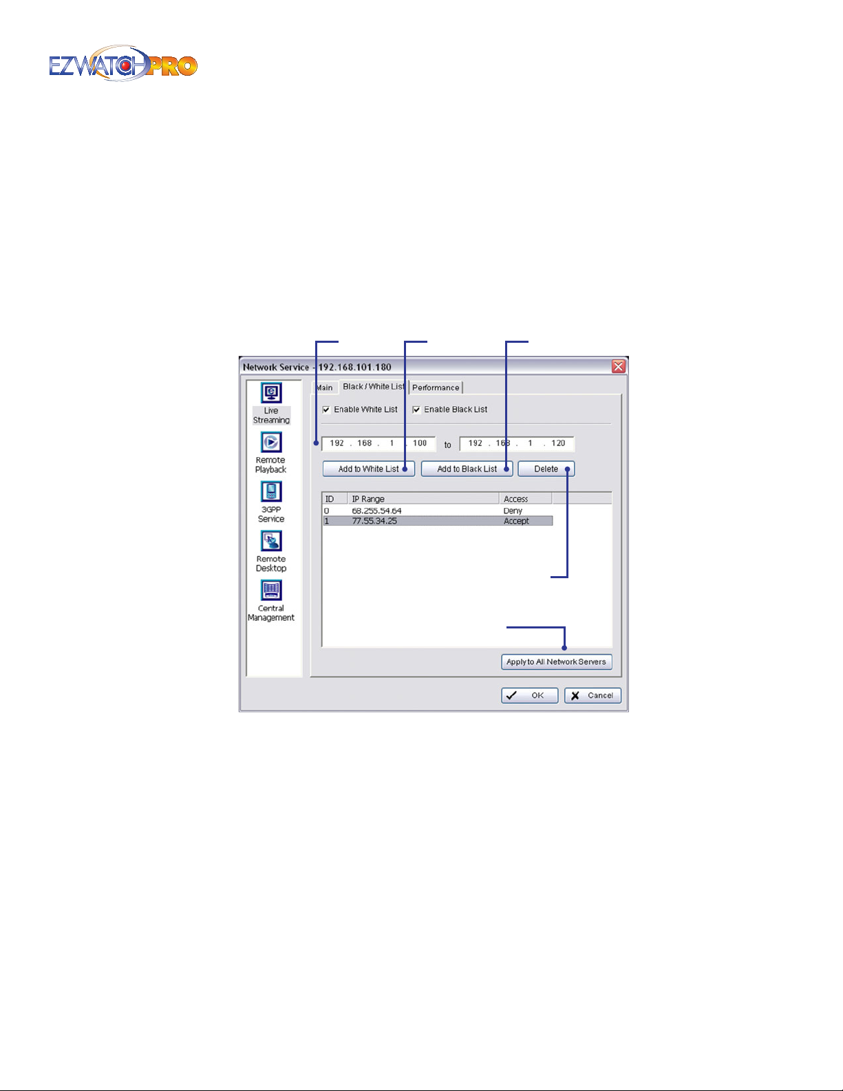
IP Field This allows you to add addresses to either list. Enter the same address in both elds if you
want to block a single address. Otherwise, enter a starting and ending range to block multiple
addresses.
Add/Delete Once you have entered a range, you may add the range to either list using the Add
buttons. If you want to remove an address from a list, highlight it and click the Delete button.
Apply to All Playback Servers Click this button to apply all settings on this page to all other
network servers.
3.15.3 Performance Tab
IP Field
White List
Black List
Add/Delete
Apply to All Playback Servers
Fig. 75. Performance tab in Network Service window
Total Bitrate This shows you the total amount of data being transmitted by all connections. This is
a useful tool to determine the amount of bandwidth being used by the live streaming server.
Individual Camera Bitrate This shows the amount of data being transmitted for the rst camera
only. Since all cameras divide bandwidth equally, this can show you how much bandwidth is being
used for each camera.
Log Viewer This will show you the times and dates that users login and view specic cameras.
3.16 Remote Playback Server
The remote playback server is the service which controls a remote user’s ability to connect and view
previously recorded videos from the video cameras. A system administrator can congure the service
to limit the number of concurrent connections, to ban people from viewing past recordings, or to
restrict access to only a few users.
Page | 55 Software User Manual
Page 57
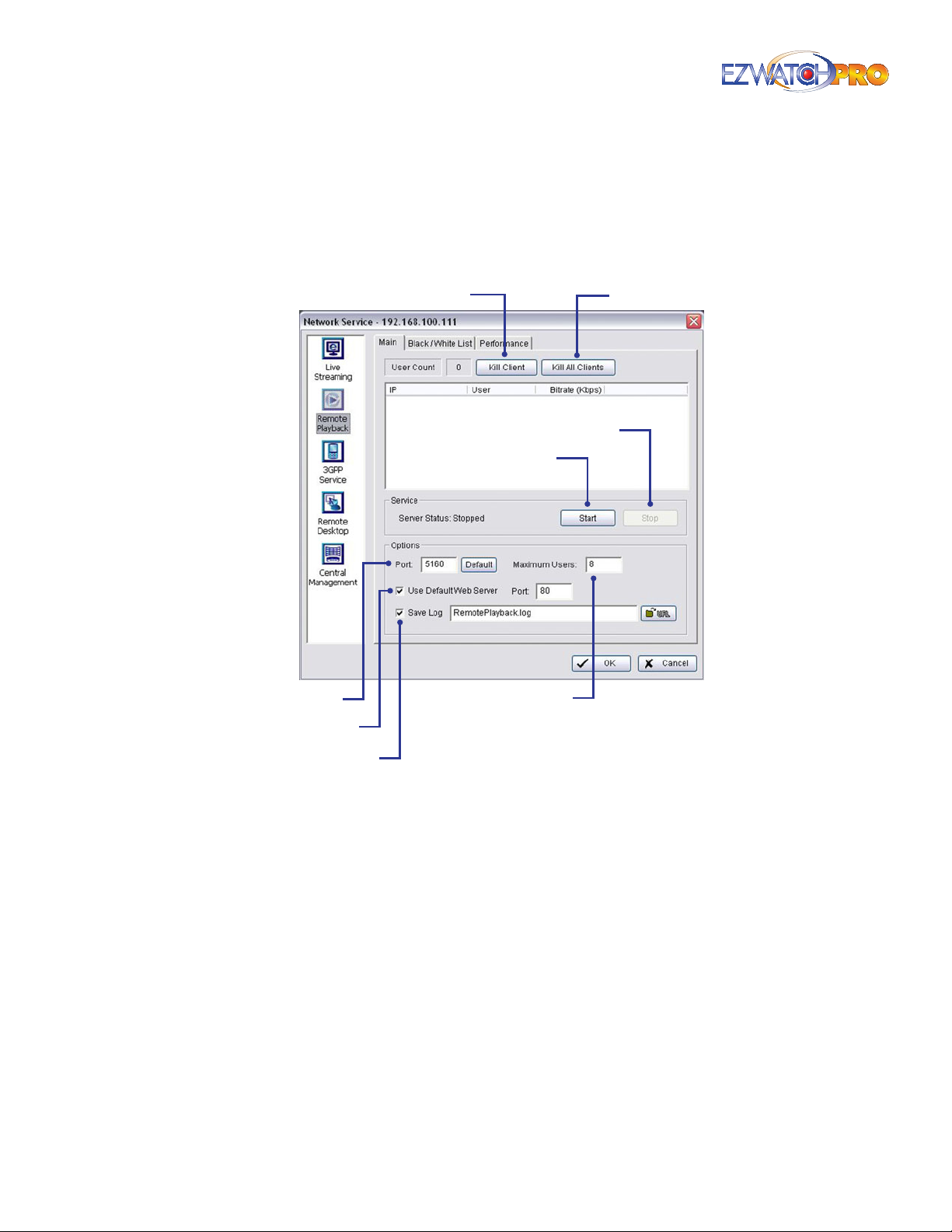
3.16.1 Main Tab
The main window allows you to see how many users are currently connected, how many cameras are
being viewed, and allows you to congure the connection options.
Kill All ClientsKill Client
Stop
Start
Port
Use Default Web Server
Save Log
Fig. 76. Main tab in Remote Playback panel of Network
Service window
Kill Client If you want to disconnect a single connection, click and highlight it in the list and click
the 'Kill Client' button.
Kill All Clients If you want to disconnect ALL connections to your system, click this button.
Start Before users can connect, the service must be started. If the server status indicates 'Running’,
the service is currently active.
Stop Click this to turn o the remote playback server. If the server status indicates 'Stopped’, then
the service is already turned o.
Options You may only adjust the Option settings when the server is stopped.
Port Assign a port for the clients to connect to your system through the network. The default
port is 5160.
Maximum Users
56 | Page Software User Manual
Page 58

Maximum Users Unlike the Remote Live Viewer, each person connecting to view the cameras
uses a single Connection (No matter how many cameras they play back). The default limit is 8
users connected and playing back clips simultaneously.
Save Log This allows you to specify the name of the log le and the location it is stored within
the PC.
Use Default Web Server If you want to view the cameras using the Internet Explorer web
browser you will need to check this box. If this box is not checked then you can only connect
using the Remote Live Viewer software from the installation CD. The default web port is 80.
► Note If you change the web port to anything other than 80, then you must
place the port at the end of the web address. For example, if your web
address is normally http://username.ezwatchip.com/ and you change
the web port to 8000, you would connect by typing in http://username.
ezwatchip.com:8000/ .
3.16.2 Black/White List Tab
The Black/White list for the Remote Playback Server functions identically to that of the Remote Live
Viewer. For additional details on how to use this feature, see 3.16.2 Black/White List Tab on Pg. 57.
3.16.3 Performance Tab
The Performance tab for the Remote Playback Server functions identically to that of the Live Streaming
Server. For additional details on how to use this feature, see 3.16.3 Performance Tab on Pg. 57.
3.17 3GPP Server
The 3GPP server is designed to allow access to the live video stream from a mobile device, most
commonly cell phones or PDA devices. Please note that not all cellular phones support this feature!
For a Cellular Device to be able to connect and view the cameras remotely, it must meet three
important criteria:
The device MUST support the 3GP Video format.
•
The device MUST support Real-Time Streaming Protocol (RTSP).
•
The device MUST be connected to a 3G Cellular network.
•
If all 3 criteria are met, then you should be able to connect and view your cameras on your mobile
device by going to the address of the system from within your device. An example URL is: rtsp://
mycameras.ezwatchip.com:554/mediaXX.3gp
The 'XX' portion of the URL can be set to which camera you want to view, with 00 corresponding to
Camera One and 03 corresponding to Camera Four.
► Note If you are unsure whether or not your cellular device meets all three
criteria, contact the device manufacturer and your cellular network
provider.
3.17.1 Main Tab
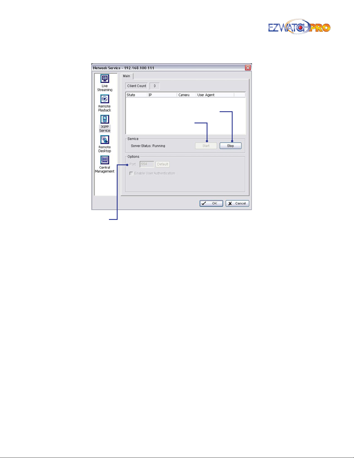
The main window allows you to see how many users are currently connected, how many cameras are
being viewed, and allows you to congure the port being used.
Page | 57 Software User Manual
Page 59
Stop
Start
Port
Fig. 77. Main tab in 3GPP Service panel of Network Service
window
Start Before users can connect, the service must be started. If the server status indicates 'Running’,
the service has already been turned on.
Stop Click this to turn the 3GPP server o. If the server status indicates 'Stopped’, then the service
is already turned o.
Port Assign a port for the clients to connect to your system through the network. The default port
is 554. You can only change the port when the service is stopped.
3.18 Remote Desktop Server
The Remote Desktop server is designed to allow a remote administrator local control over the
computer. The remote administrator can enter commands, perform actions, and control the mouse
as if they are sitting in front of the computer locally. To use this feature, you must install the Remote
Desktop software from your EZ Watch Pro CD. For details, see 3.45.2 Remote Desktop Viewer on Pg. 101.
3.18.1 Main Tab
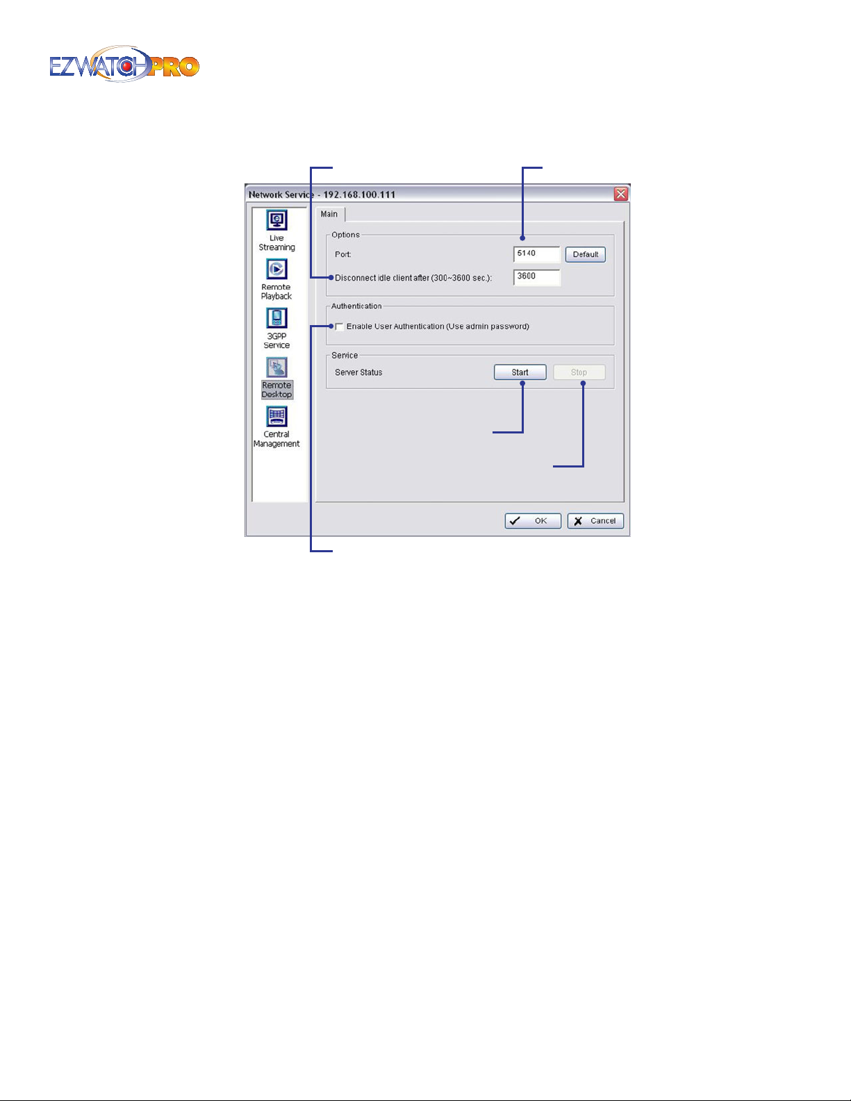
The main window allows you to congure the port being used, idle disconnections, and user
authentication.
Port Assign a port for the clients to connect to your system through the network. The default port
is 5140. You can only change the port when the service is stopped.
58 | Page Software User Manual
Page 60
Disconnect Idle Client
Start
Authentication
Port
Stop
Fig. 78. Main tab in Remote Desktop panel of Network
Service window
Disconnect Idle Client If the system does not receive any commands from the remote computer
after a specied number of seconds, it will disconnect the connection.
Authentication When checked, the remote administrator must input the admin password when
he wantes to connect to take control of the system.
Start Before users can connect, the service must be started. If the server status indicates 'Running’,
the service has already been turned on.
Stop Click this to turn the Remote Desktop server o. If the server status indicates 'Stopped’, then
the service is already turned o.
3.19 Central Management Server
For information regarding this feature, please refer to the section on Central Management found in
3.14 Network Service Conguration, Pg. 51.
3.20 Playback Conguration
The Playback System is used to watch recorded video, backup video clips, view, and/or search for
unusual events, and recorded system information.
You can access the Playback System by clicking the Playback button from the Main Console, or you can
access the application using the Windows program list.
Page | 59 Software User Manual
Page 61
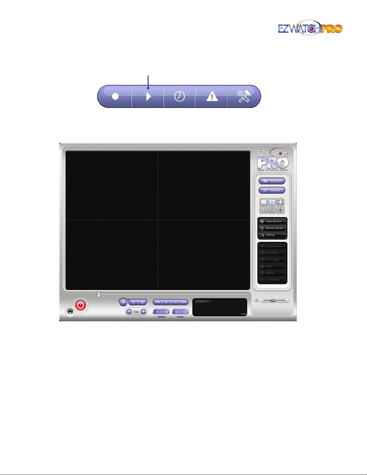
Playback
Fig. 79. Playback button
3.21 Playback Toolbars
Fig. 80. Playback console
Minimize minimizes the Playback console.
Exit shuts down the Playback console.
Scroll Bar shows you how far you are into the current video. By clicking and dragging the slider
you can move to dierent times in the current video.
Control Display displays the time, date, cue in/cue out points, and speed of the video.
Control This will Play, Pause, and Stop the video.
60 | Page Software User Manual
Page 62
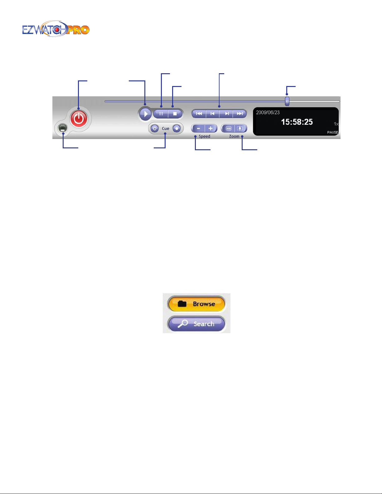
Exit
Play
Pause
Stop
Fast REV | Frame REV | Frame FWD | Fast FWD
Scrollbar
Minimize
Fig. 81. Playback controls in Playback console
Cue When playing video, you can click on the Cue In/ Cue Out buttons where you want to set the
starting/ending point of a saved video clip or a backup le. The Cue In and Cue Out time will be
displayed in the Playback Information screen once they are set.
Speed This controls the speed of the playing video. Click + to speed up and – to speed down the
video.
Zoom This allows you to zoom in and zoom out of the video for a better view. Move to the spot
you want to view using the mouse to drag the video to the position you want.
► Note Using the left mouse button click down on the screen, holding the
button down move the mouse. The video will 'drag' in the direction you
move the mouse.
Frame FWD/REV When playing video, you can skip forward or reverse individual frames of the
video.
Fast FWD/REV When playing back video, you can fast forward or fast reverse the video.
Cue
Speed
Zoom
Fig. 82. Browse and Search buttons in Playback console
Browse Mode This is the normal playback function, which allows you view video normally from
multiple cameras at a time.
Search Mode This playback function will allow you to search for a specic event (Motion, Missing/
Foreign Object, etc.) on a single camera image. This is useful for nding a specic event when
browsing long durations of video.
Page | 61 Software User Manual
Page 63
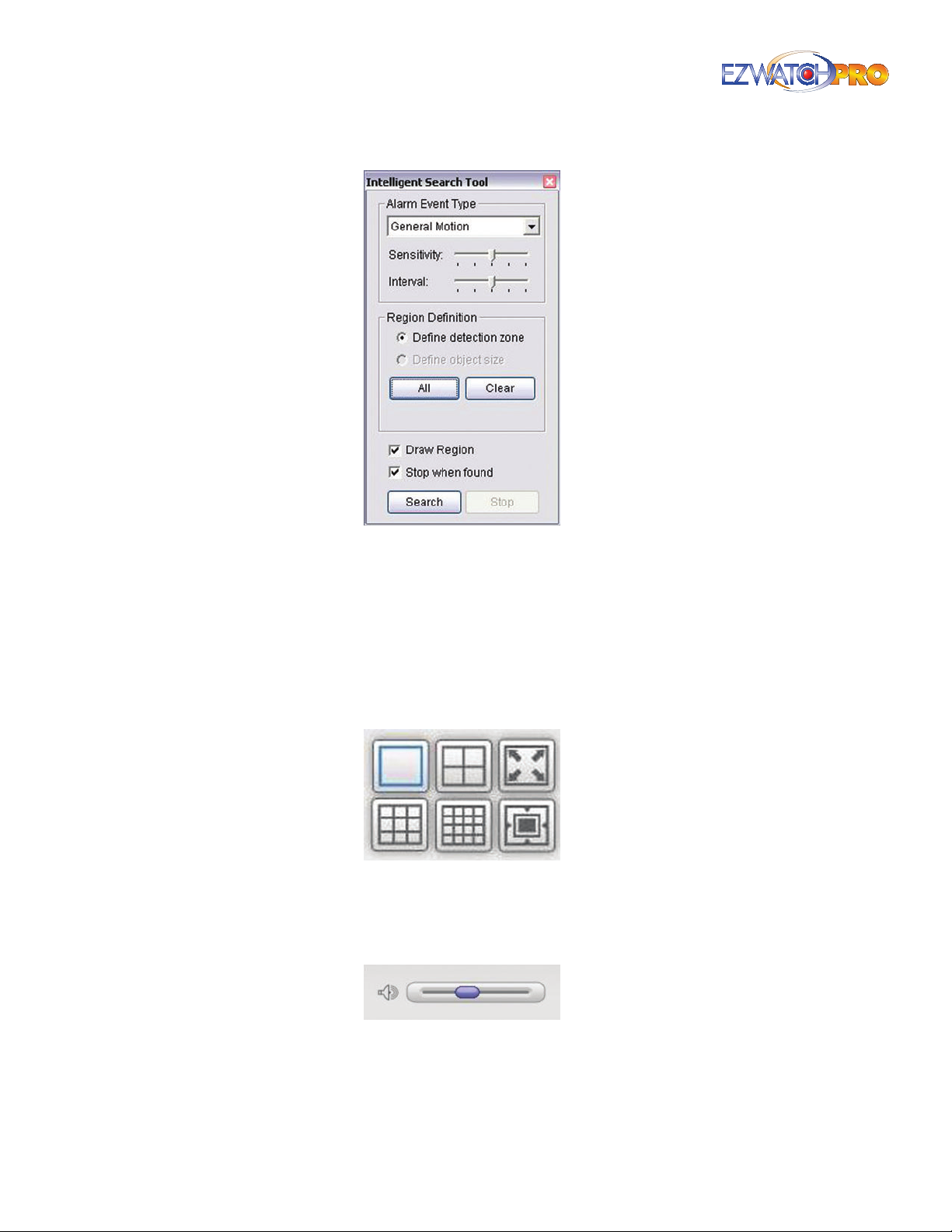
Fig. 83. Intelligent Search Tool window
Intelligent Search Tool Window Click on the Search Mode button to access the Intelligent
Search Tool window. Setup unusual events here to detect abnormalities that occurred during
the recording period. For more information regarding Events, please refer to 3.31 Smart Guard
Conguration on Pg. 74.
Screen Division This allows you to select how the cameras are displayed on the screen during
playback. Selecting larger divisions than you have cameras will result in blank areas on the
playback screen, while selecting smaller division will mean not all of your cameras will be visible
on the playback screen.
Fig. 84. Window Division selections in Playback console
Audio Volume Control Adjust the sound level of video you are currently playing back. For more
information on recording audio, please refer to the section on Audio in 3.2 Encoding Options
Conguration, Pg. 20.
Fig. 85. Audio Volume Control in Playback console
62 | Page Software User Manual
Page 64
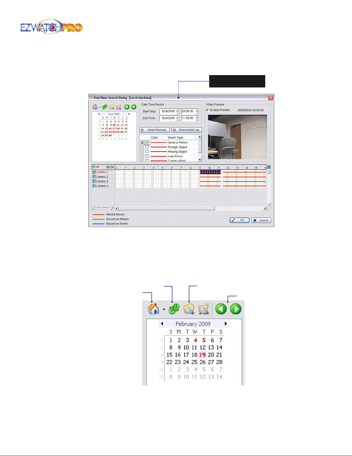
3.21.1 Open Record
Fig. 86. Open Record button launches DateTime Search
Dialog window
You can click on Open Record to launch the DateTime Search Dialog window which allows you to
specify what period of time you want to playback.
3.21.2 DateTime Search Dialog Window
Remote Playback
Access
Site Management
Fig. 87. Calendar section of DateTime Search Dialog
window
Refresh
Access
Log Viewer Dialog
Scroll
Page | 63 Software User Manual
Page 65
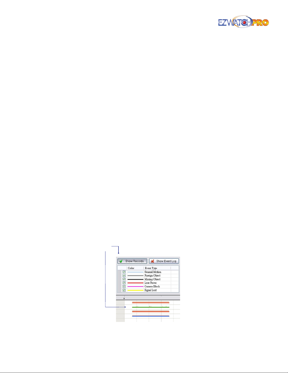
Calendar Window The calendar window allows you to see, at a glance, the dates that the system
has recorded. Dates that appear in bold red numbers contain recordings, while numbers that
appear in normal black text do not contain recordings.
Click on the House icon on the top of the display window to obtain the Remote Playback Site
Management dialog. Here you may select to access local machine or set up remote playback
server. Refer to 3.16 Remote Playback Server on Pg. 55 for more details.
Click on the Refresh icon to refresh the record display window, and click on the Magnifying Glass
icon to access the Log Viewer dialog. Refer to 3.30 Log Viewer on Pg. 74 for more details.
Additionally, utilize the left and right arrow icons to scroll between dates that contain recordings.
Date Time Period If you want to view recordings spanning multiple dates, enter those dates and
times into these elds.
Video Preview Check the Enable Preview box to view the selected video.
Show Records If this option is selected, you will see a thin red line above each of the scheduled
lines in the Time Table. The thin red line indicates times when the system has recorded data. Often
motion detection shows a broken red line, with the gaps indicating time periods when motion was
not detected.
Event Type There are 6 event types. You may set up dierent colors for dierent event types to
help you select events. For more information regarding Events, please refer to 3.31 Smart Guard
Conguration on Pg. 74.
Time Table The time table allows you to see, at a glance, which cameras recorded during which
times. The numbers across the top of the time table indicate hours, with 0 representing 12:00
AM and 23 representing 11:00 PM. Next to the camera names will be lines that indicate when
the camera was recording. A red line indicates constant recording, a green line indicates motion
detection recording, and a blue line indicates recording triggered via an event.
The +/- buttons allow you to select all Cameras (+) or No Cameras (-) to playback. You can also
select or deselect a specic camera by clicking on it.
If you want to shrink the Time Table to see more times at once, slide the magnication scale left. To
expand and see ner detail of recordings, slide the scale right.
Show
Records
Fig. 88. Show Records button and display
64 | Page Software User Manual
Page 66
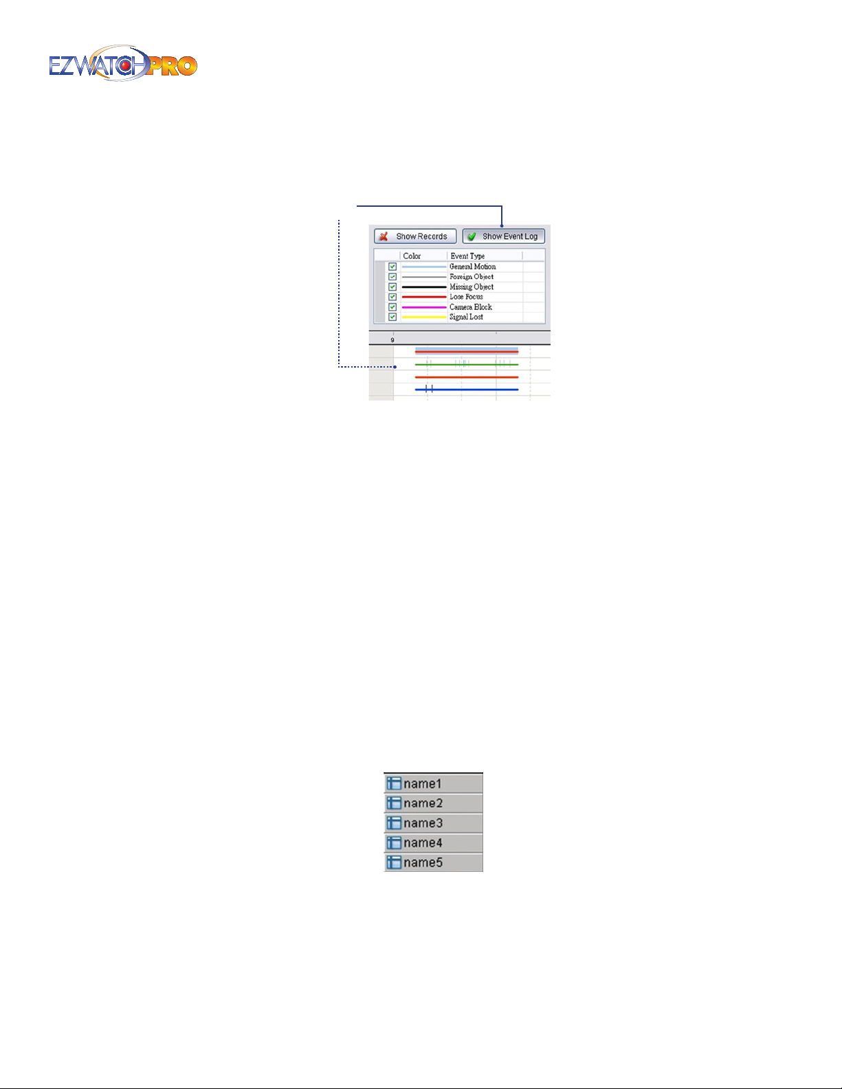
Pressing the button 'Show Records' makes the Time Table show the period of recording data as
shown in Fig. 88.
Show
Event Log
Fig. 89. Show Event Log button and display
Pressing the button 'Show Event Log' makes the Time Table show the time of event detection as
shown in Fig. 89.
3.21.3 To Withdraw the Record
■ Step 1 From the record display window at the top left of the Date Time Panel, select the date for
which you want to withdraw the record. The red/green/blue lines shown on the time table indicate
available recorded video records.
► Note The record display window can be shown in calendar view or list
control view. To modify the setting of the record display window, click
on the Setting button at the right of the Playback Console. Refer to 3.24
Playback Setting on Pg. 69 for more details.
■ Step 2 Use color bars to dierentiate event types from each other. This will help you select video
clips.
■ Step 3 Highlight the video clip you want to review by left-clicking and dragging the time period.
You may also utilize the Start Time and End Time in the DateTime Period eld set. Additionally,
modify the scale of the Time Table with the + and – signs on the bottom left.
Fig. 90. Camera names list in Playback console
■ Step 4 Check the Enable Preview option to get the preview of the video you select.
■ Step 5 Click the camera name to add or remove cameras you want to playback.
■ Step 6 Click 'OK' when completing the setting.
Page | 65 Software User Manual
Page 67
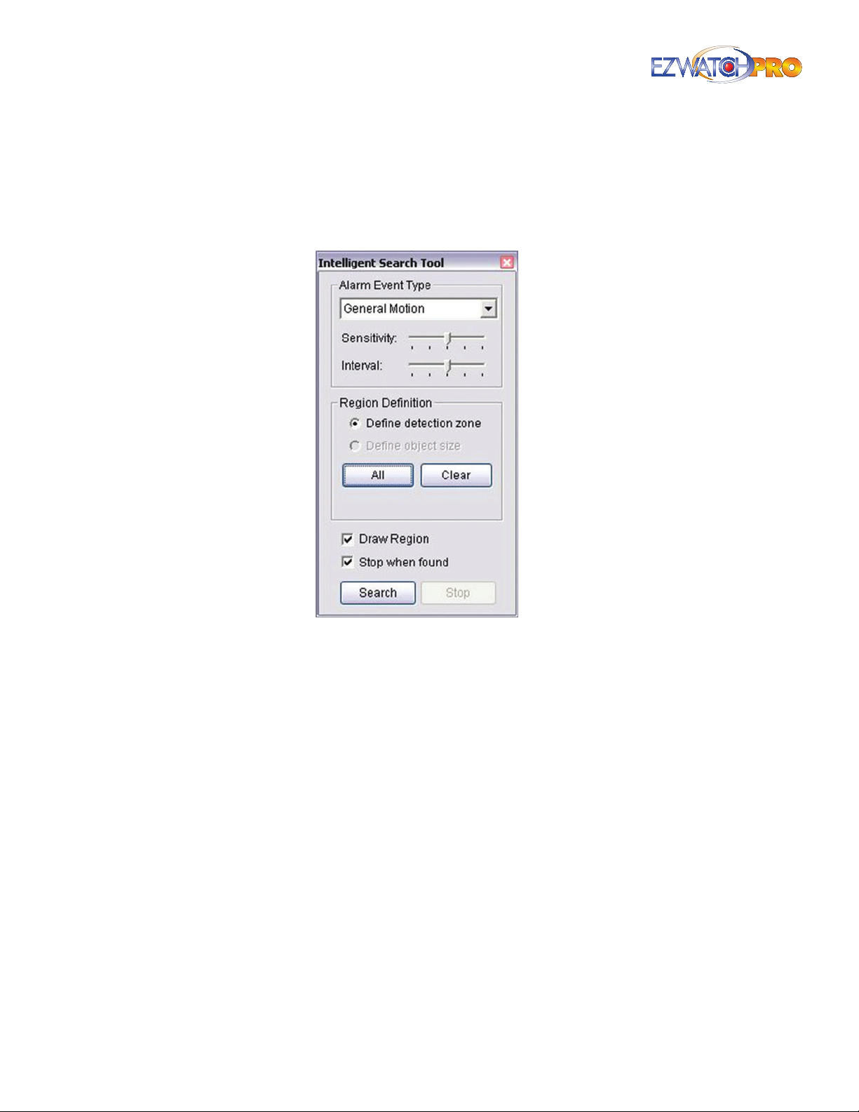
3.22 Alarm Event Types
3.22.1 General Motion
General Motion detects all movements in the dened area.
Fig. 91. General Motion setting in Intelligent Search Tool
window
Dene Detection Zone Left-click and drag to draw a detection zone. You may dene more than
one zone on the screen by repeating the process.
Sensitivity Modify the sensitivity setting by moving the slider. Moving the slider toward the right
increases the sensitivity level, which means a relatively small movement will trigger the alarm.
Conversely, moving the slider toward the left reduces the sensitivity for movement detection.
Setting up an appropriate sensitivity level reduces the frequency of false alarm. For instance, you
can lower the sensitivity to avoid the alarm being triggered by a tree swinging in a breeze.
Interval Move the slider to the right to increase time interval so that the alarm will only be
triggered when the movement is of a longer duration. Move to the left to reduce the time interval.
Stop When Found Check this option to have the video stopped when detecting motion in the
detection zone. Uncheck the option to have video keep rolling, and all detected events will show
on the list in search result box. Click on the listed event in the box to jump to the point in the video
where a motion was detected.
3.22.2 Foreign Object
Foreign Object Alarm is activated when any additional object appears in the dened area on the
screen.
66 | Page Software User Manual
Page 68

Dene detection zone Before detecting foreign objects, a detection zone must be dened. To
dene a detection zone, left-click and drag on the screen. An alarm will be triggered when any
additional object appears in the detection zone.
Dene object size Drag and draw on the screen to dene the size of a foreign object.
Sensitivity Modify the sensitivity setting by moving the slider. Moving the slider toward the right
will increase the sensitivity level, which means a relatively small movement will trigger the alarm.
Conversely, moving the slider toward the left will reduce the sensitivity for movement detection.
Interval Clicking and moving the slider to the right increases the time interval so that the alarm
will only be triggered when the object has been out of the detection zone for a longer duration.
Moving the slider to the left reduces the time interval.
Establishing an appropriate Interval value will reduce the chance of false alarm. For example, you
can lower the Interval to avoid the alarm being triggered by a pedestrian.
3.22.3 Missing Object
Missing Object Alarm is activated when the selected object is removed from the dened area on the
screen.
Dene detection zone Before detecting a missing object, a detection zone must be dened.
Left-click and drag to draw a detection zone. Alarm will be triggered when the dened object is
removed from the detection zone.
Dene object size This tells the system how large the dened object is. Drag and draw a square
that is about the same size as the object that you want to protect on the screen.
Sensitivity Modify the sensitivity setting by moving the slider. Moving the slider toward the right
will increase the sensitivity level and a relatively small movement will trigger the alarm. Conversely,
moving the slider toward the left will reduce the sensitivity for movement detection.
Interval Click and move the slider to the right to increase the time interval so that the alarm will
only be triggered when the movement is of a longer duration. Moving the slider to the left reduces
the time interval.
3.22.4 Lose Focus
Lose Focus alarms when any camera loses its focus.
3.22.5 Camera Occlusion
Camera Occlusion alarms when any camera is blocked.
3.23 Remote Server
This feature allows you to remotely playback clips from an osite location.
Page | 67 Software User Manual
Page 69
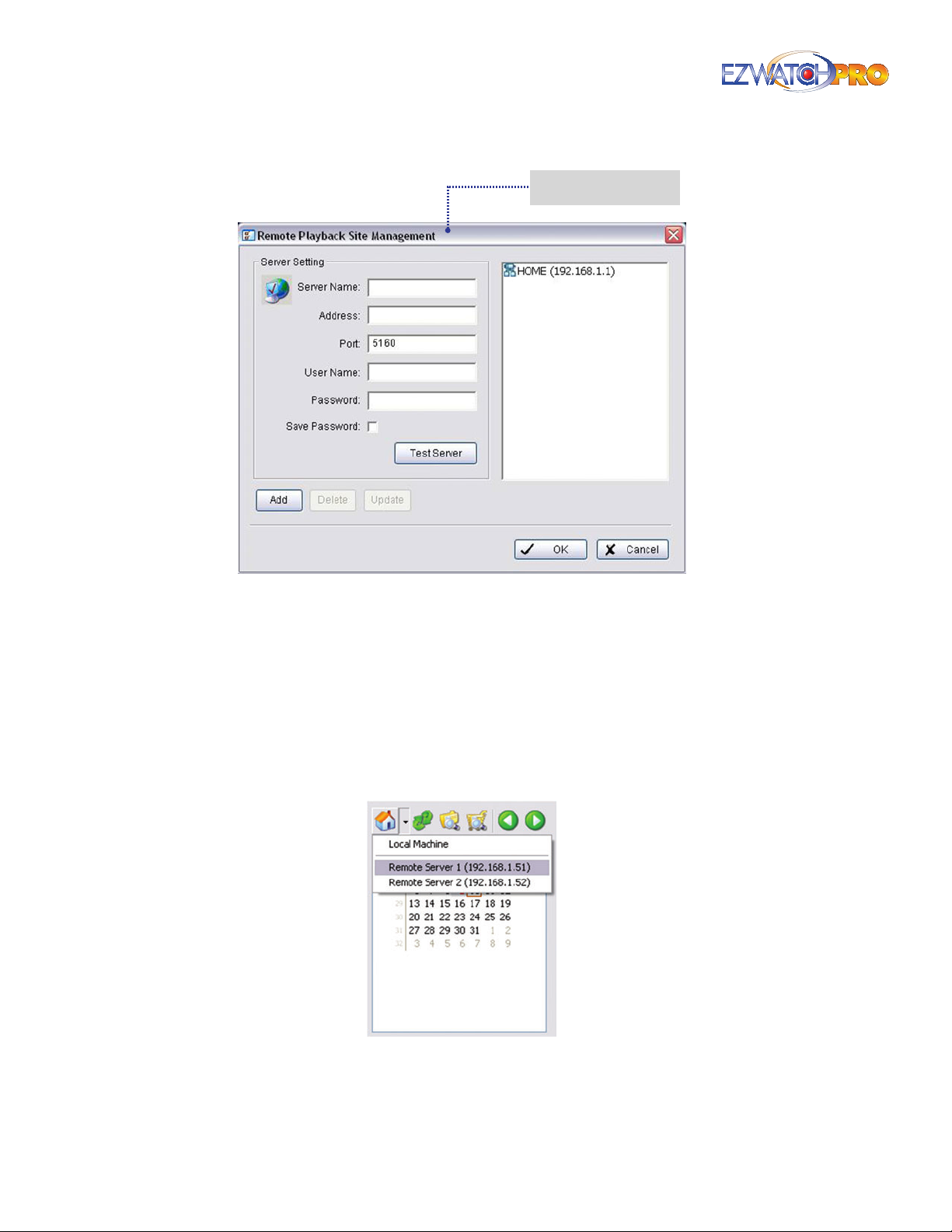
Fig. 92. Remote Playback Site Management button and
window
Connect to a Remote Playback Site
■ Step 1 Enter the IP address or DNS, Port, Username, and Password.
■ Step 2 Click 'Add' to create the site.
■ Step 3 Click 'OK' to exit the Remote Playback Site Management window.
■ Step 4 Once you have created a Remote Playback Site, click on the 'Open Record' button to
access the DateTime Search Dialog window.
Fig. 93. Calendar section of DateTime Search Dialog section
■ Step 5 From the DateTime Search Dialog window, click on the House icon on the top of the
display window to access the Remote Playback Site.
68 | Page Software User Manual
Page 70
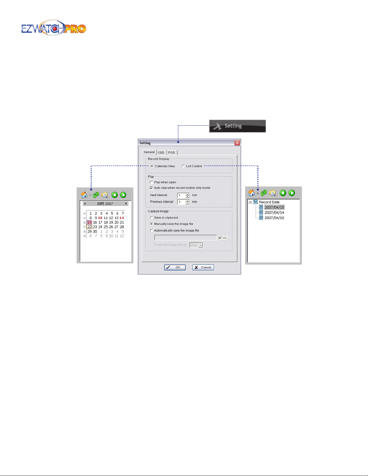
■ Step 6 You are now connected to a Remote Playback Site. The Remote Playback Site functions
identically to that of the Local Playback Site. For additional details on how to the Playback feature,
see 3.20 Playback Conguration on Pg. 59.
3.24 Playback Setting
This feature allows you to adjust the settings of the Playback service.
Fig. 94. General tab in Setting window
3.24.1 General Tab
Calendar View Make the record display windows as calendar view.
List Control Make the record display windows as list control.
Play when open Check this option to set the system to start playing the video clip every time
when a record is withdrawn.
Auto skip when record motion only mode Check this option to set up the system to
automatically skip to the points where there were motions recorded.
Next interval Set the interval by which the video moves forward when you click on the Next icon
on the control panel.
Previous interval Set the interval by which the video moves backward when you click on the
Previous icon on the control panel.
Capture Image Setup how you want to save images.
Save in clipboard The image will be saved in the clipboard and can be pasted into other
application software.
Page | 69 Software User Manual
Page 71
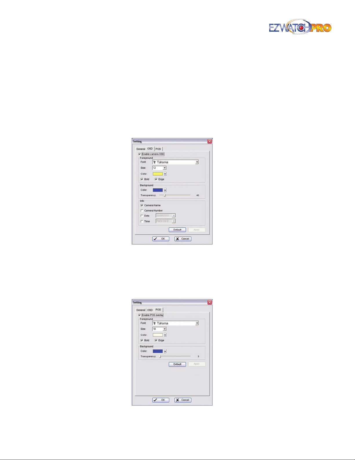
Manually save the image le You can manually select where you want to save the image, name
the saved le, and choose the format in which you want to save the image.
Automatically save the image le By pre-setting a path/URL and the image format, the system
will automatically save the image accordingly when you click the Save button in the control panel.
3.24.2 On Screen Display (OSD) Tab
Enable Camera OSD Display video information on recorded video. The information includes
camera name, camera number, date, and time. User also can set up OSD font, including the font,
font size, font color, and any desired font eects.
Fig. 95. On Screen Display (OSD) tab in Setting window
3.24.3 Point Of Sale (POS) Tab
Display video information on recorded video. The information includes camera name, camera number,
date and time. User also can set up OSD font, including the font, font size, font color and any desired
font eects.
Fig. 96. Point of Sale (POS) tab in Setting window
70 | Page Software User Manual
Page 72

3.25 Enhancement
The enhancement window allows you to digitally modify the image to attempt to make it look better,
either by sharpening the image for better clarity or by adjusting the colors to make something more
visible.
General Setting Check the option and choose whether you want to apply the setting to all the
channels or only to those currently shown on the screen.
Fig. 97. Post Processing Tool window
3.25.1 Filter Setting
Visibility Check this option and move the slider to adjust the gamma value of the image to
enhance the image and make it clearer.
Sharpen Check this option to activate this function. Move the slider to the right to sharpen the
image or to the left to soften it.
Brightness Check this option to activate this function. Move the slider to the right to make the
image brighter.
Contrast Check this option to activate this function. Move the slider to the right to increase
contrast.
Grey Scale Check this option to display the record in grey scale mode so the image displays in
black and white.
3.26 Save Video
This feature allows you to export a video le you are currently playing back.
Page | 71 Software User Manual
Page 73
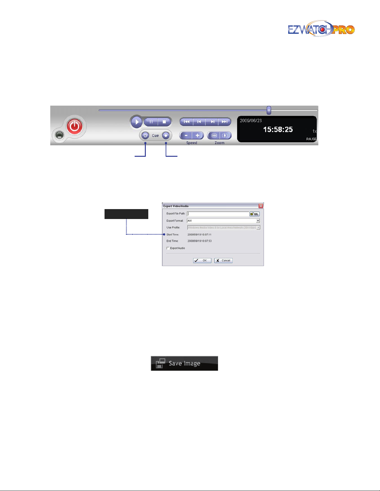
■ Step 1 Click on the display screen to choose the camera display that you want to save as a video
clip.
■ Step 2 Set up the cue in and cue out points. The cue in and cue out time will show in the
information window.
Cue In Cue Out
Fig. 98. Cue In and Cue Out buttons in the Playback console
■ Step 3 Click Save Video button, choose the folder in which you want to save the le, enter the le
name, and click 'Save’.
Fig. 99. Save Video button and Export Video/Audio window
■ Step 4 Set the Export Format as ASF (recommend) or AVI and set the Use Prole.
■ Step 5 You may export (save) the record with both video and audio or video only.
■ Step 6 Click 'OK' to save the video.
3.27 Save Image
This feature allows you to save an image le from the video you are currently playing back.
Fig. 100. Save Image button
■ Step 1 Click on the display screen to choose the camera display from which you want to save
pictures.
■ Step 2 Click Save Image button when the image you want is shown on the screen. You may click
Pause to freeze the video, use the Step Forward/Step Backward function to nd the image(s) you
want to save.
■ Step 3 Choose the folder and the image format (BMP or JPEG) you prefer and then click save.
72 | Page Software User Manual
Page 74
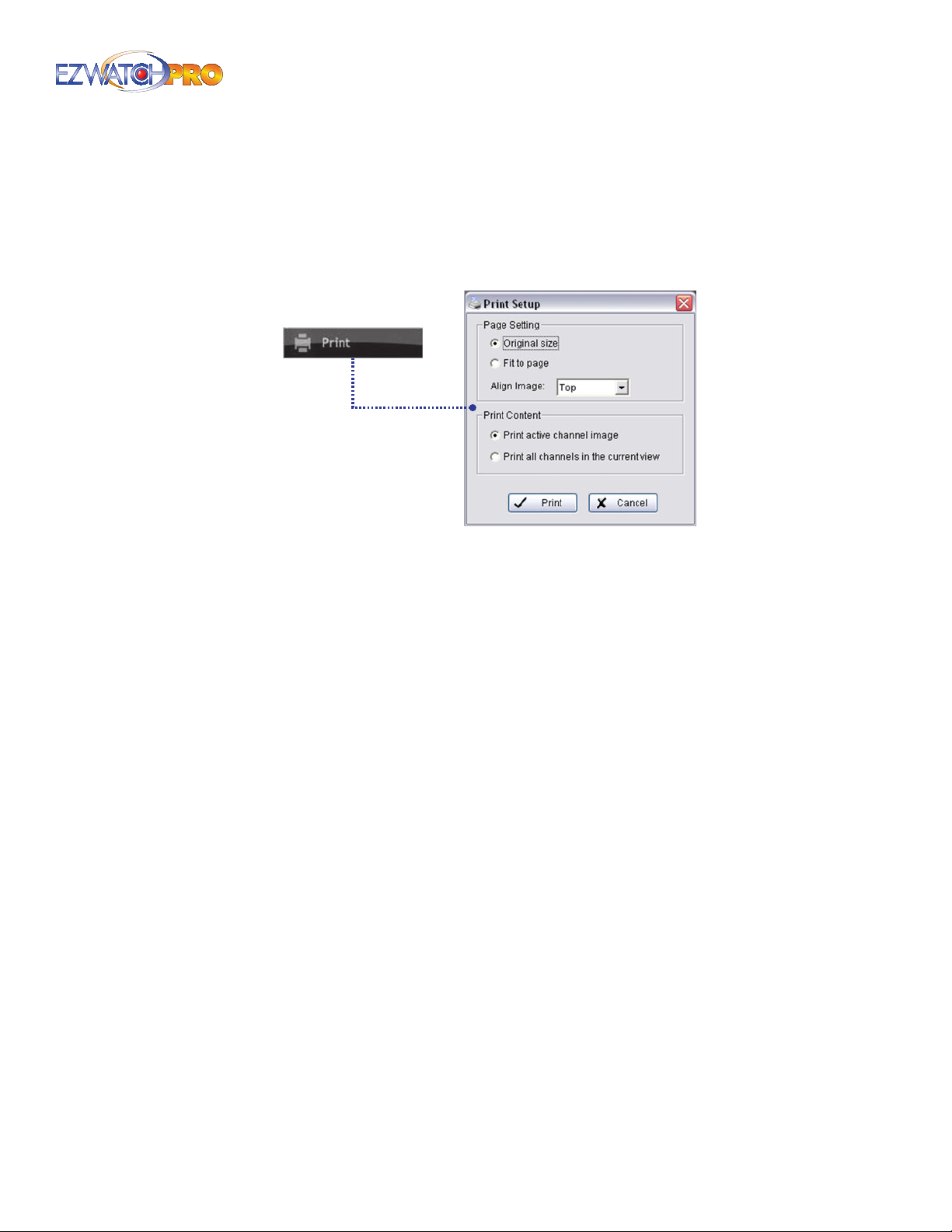
► Note You may skip Step 3 by presetting a folder and format in which you
want to save the images.
3.28 Print
This feature allows you to print the current image of the video le you are playing back.
Fig. 101. Print button and Print Setup window
Original Size Select to have the image print in original size.
Fit to page Select to have the image t the page.
Align Image Top, Center, or Bottom
Print Content Print the image from the currently selected channel or all the channels shown on
the screen.
3.29 Backup
Dierent from Save Video, the Backup function saves everything from the Playback panel, including
log information.
You can start a full function Playback Console and load the backup les on any PC with a Windows
operating system. This means you may monitor the real-time video and simultaneously work on the
backup les on separate computers.
■ Step 1 Press 'Open Record' to select data and press 'Backup'.
■ Step 2 Adjust the Start Time and End Time you want to backup.
■ Step 3 Adjust the Cameras you want to backup.
■ Step 4 Calculate the size of the backup data.
■ Step 5 Select the directory in which you want to save the backup data.
■ Step 6 Check the log you want to backup.
■ Step 7 Press 'Backup' to start backing up.
Page | 73 Software User Manual
Page 75
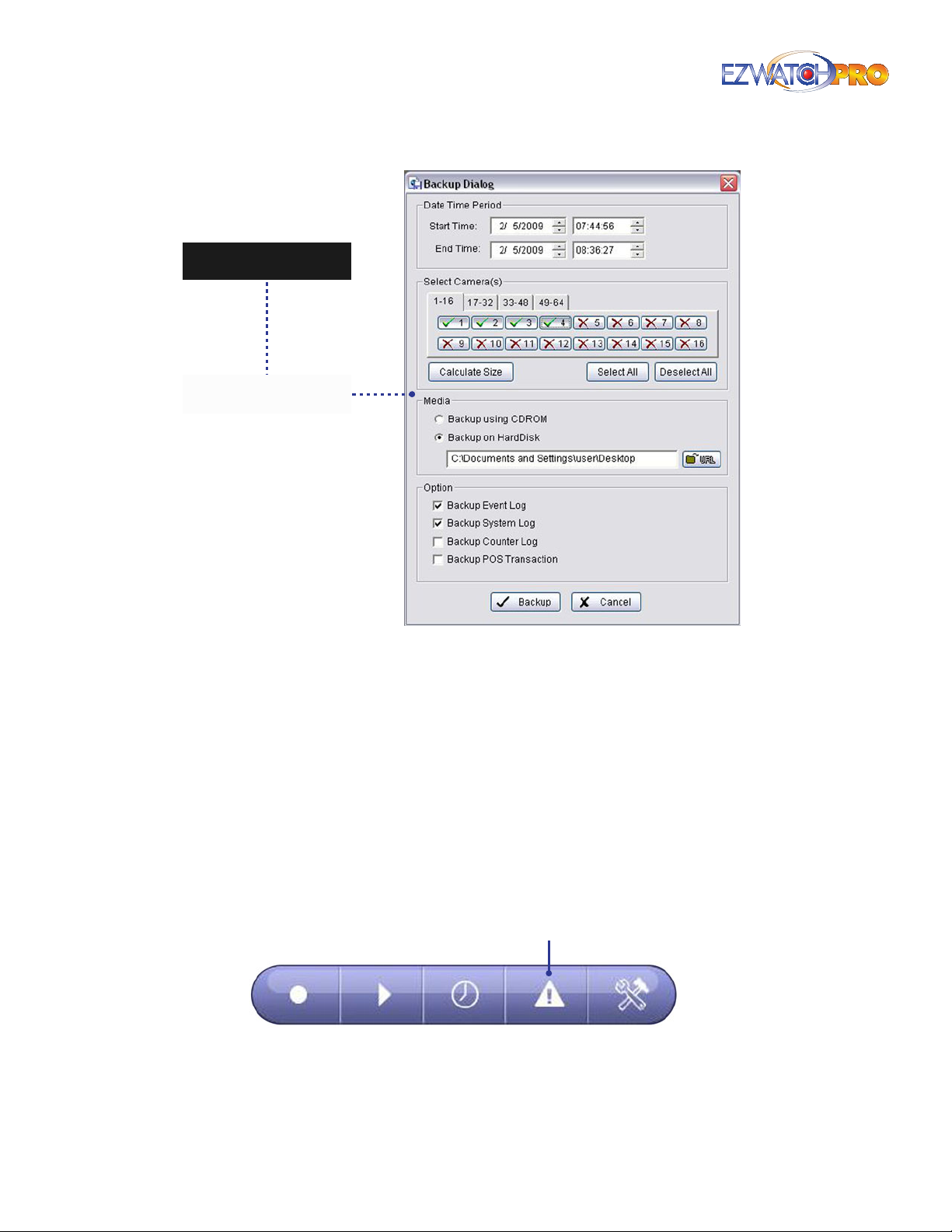
Fig. 102. Open Record button and Backup button and
Backup Dialog window
3.30 Log Viewer
The log viewer keeps a record of special events which occur within the system. Events can consist of
Smart Guard alerts, System alerts, and attempts to log in or out both locally and remotely.
The Log Viewer functions identically to that of the Log Viewer in Congurations. For additional details
on how to use this feature, see 3.10 Point Of Sale (POS) Log on Pg. 48.
3.31 Smart Guard Conguration
The Smart Guard is a system that can alert you should any unusual event such as a missing or foreign
object alarm be triggered. These alerts can consist of sound/alarms, phone call, or e-mail notications.
Smart Guard
Fig. 103. Smart Guard button
74 | Page Software User Manual
Page 76
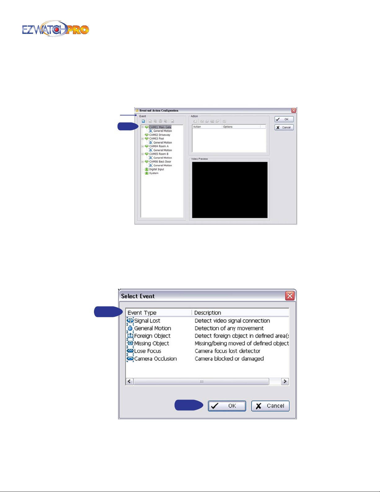
3.31.1 Event Conguration
There are three sources of events: Camera (video image), Digital Input (device connected to your PC)
and System (condition of your hardware). You can assign multiple events by following the instructions
below.
Insert Event
Step 1
Fig. 104. Event and Action Conguration window
3.31.2 Assign a Camera Event
■ Step 1 Select a channel from the camera list and click the insert event icon.
■ Step 2 There are six types of events: Signal Lost, General Motion, Foreign Object, Missing Object,
Lose Focus, and Camera Occlusion. Select the event you want on the Event Type list.
Step 2
Step 3
Fig. 105. Select Event window
■ Step 3 Click 'OK' to congure the setting of the Event Type. Refer to the following sections.
Page | 75 Software User Manual
Page 77
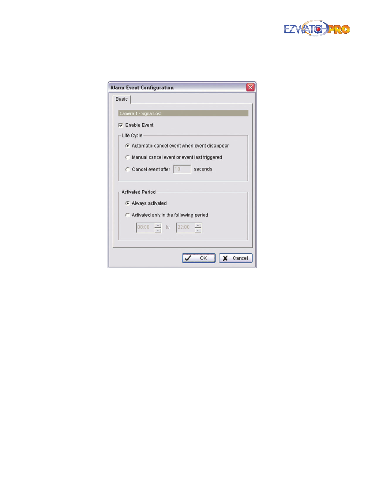
3.32 Event - Signal Lost
Fig. 106. Basic tab in Alarm Event Conguration window
3.32.1 Basic Tab
Enable Event Check the box to activate.
Automatically cancel event when event disappear The alarm/action will be o once the
abnormality is xed or ends.
Manually cancel event or event last triggered The alarm/action will continue until it is canceled
from the Main Console (Start>Open Event Report>Cancel All Events). The user currently not at the
seat watching the screen will be notied by the alarm.
Cancel event after time-out XX seconds Enable checkbox and setup the time-out seconds to
cancel the event after the time that you set whatever the events disappear or not.
Activated Period Set up the system to react during a certain time period, for example, during
oce hours.
76 | Page Software User Manual
Page 78
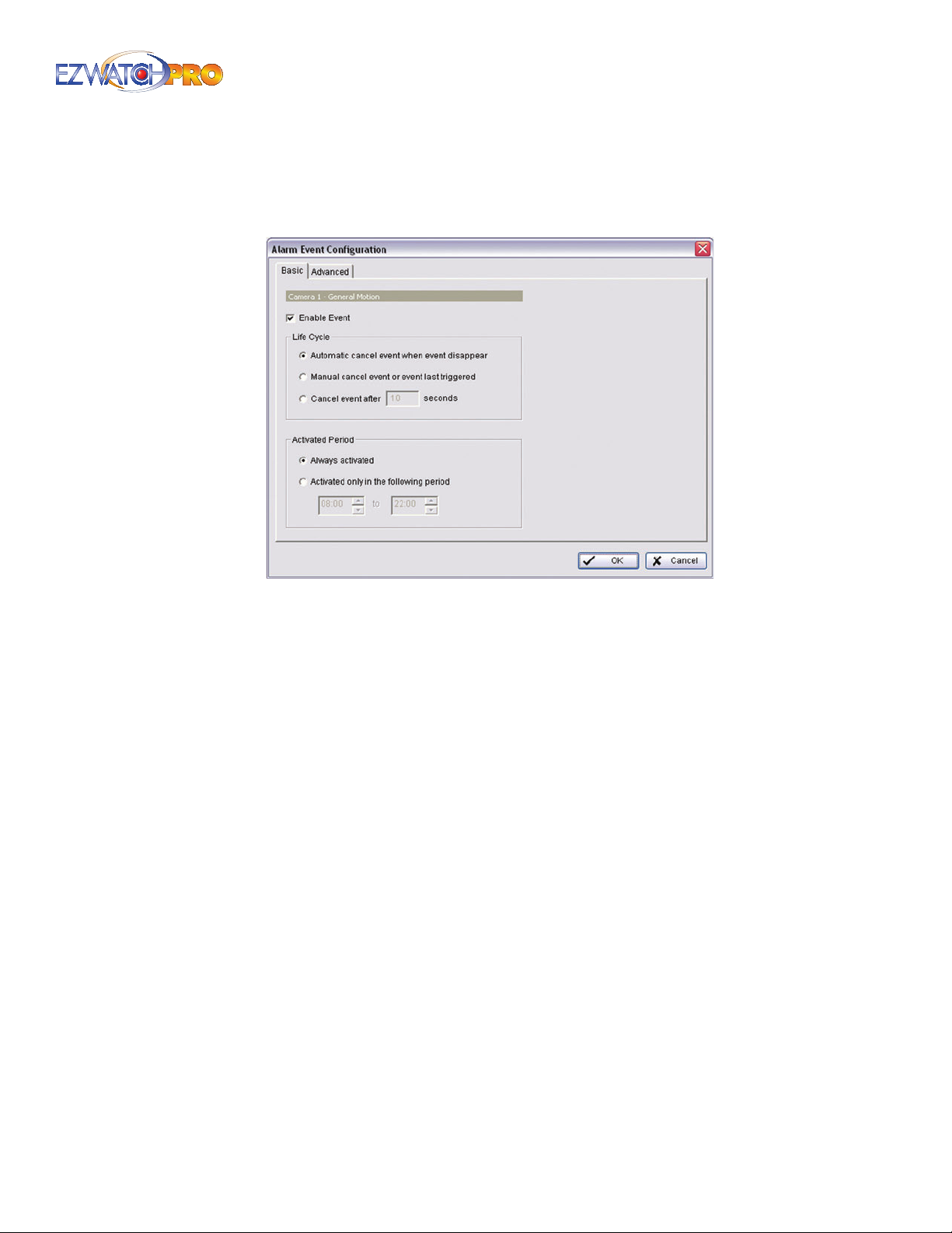
3.33 Event - General Motion
Detect any movement in the dened detection zone.
Fig. 107. Basic tab in General Motion Alarm Event
Conguration window
3.33.1 Basic Tab
Enable Event Check the box to activate.
Automatically cancel event when event disappear The alarm/action will be o once the
abnormality is xed or ends.
Manually cancel event or event last triggered The alarm/action will continue until being
canceled from the Main Console (Start>Open Event Report>Cancel All Events). The user currently
not at the seat watching the screen will be notied by the alarm.
Cancel event after time-out XX seconds Enable checkbox and setup the time-out seconds to
cancel the event after the time that you set whatever the events disappear or not.
Activated Period Assign the system to activate during a specied time period.
Page | 77 Software User Manual
Page 79
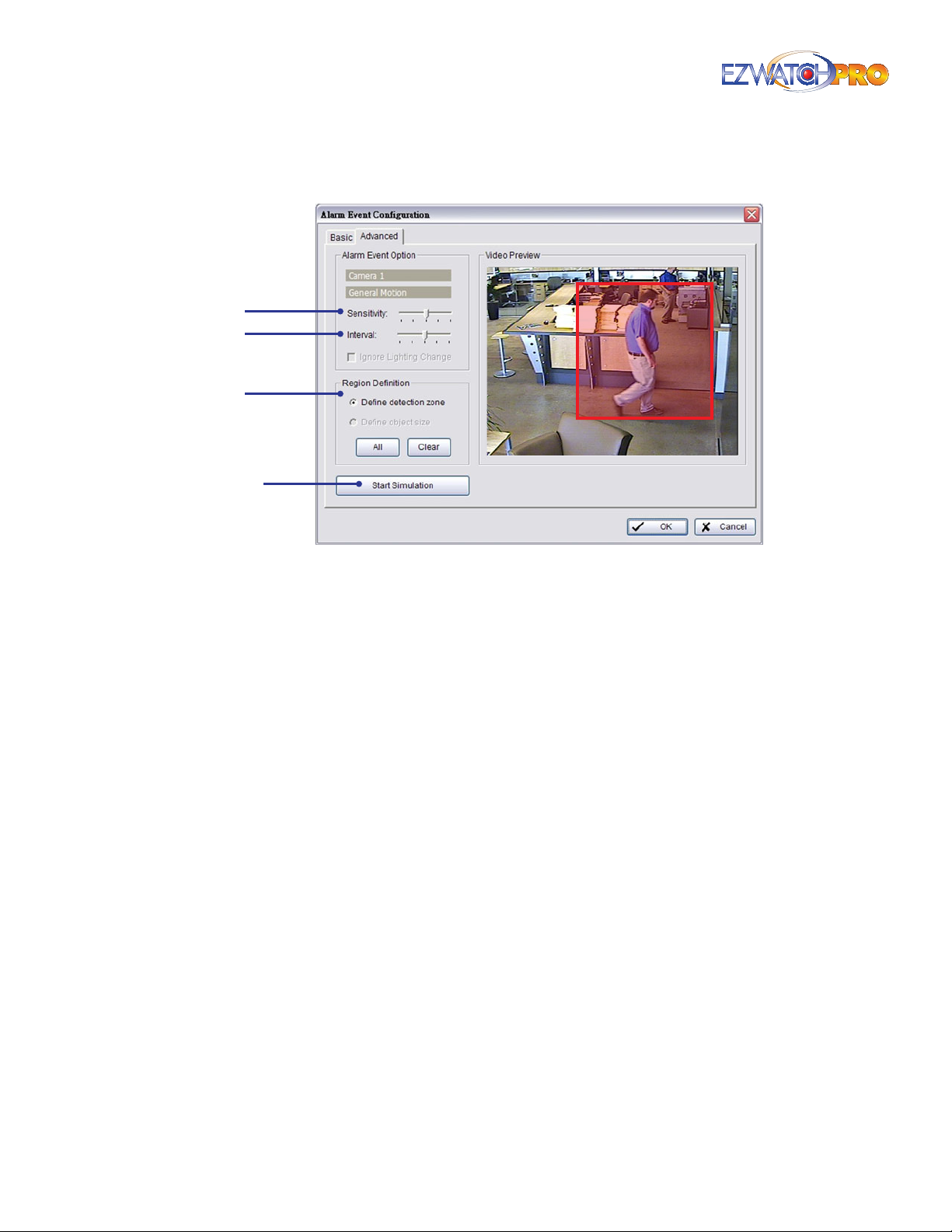
3.33.2 Advanced Tab
Sensitivity
Interval
Region
Denition
Start
Simulation
Fig. 108. Advanced tab in General Motion Alarm Event
Conguration window
Sensitivity Click and move the slider to the right to increase sensitivity so that a relatively small
movement will trigger the alarm. Move the slider to the left to reduce the sensitivity of movement
detection. Establishing an appropriate Sensitivity value will reduce the chance of false alarms. For
example, you can lower the Sensitivity to avoid the alarm being triggered by tree swinging in a
breeze.
Interval Click and move the slider to the right to increase interval time so that the alarm will be
triggered only when the movement is of a longer duration. Move the slider to the left to reduce
the interval time.
Region Denition To detect General Motion, you have to dene a detection zone. Left-click and
drag the mouse to draw a detection zone. You may dene more than one zone on the screen by
repeating the same process. User can also click on 'All' button to select the entire detection zone.
Start Simulation Click the Start Simulation button and test the function on the preview screen.
78 | Page Software User Manual
Page 80
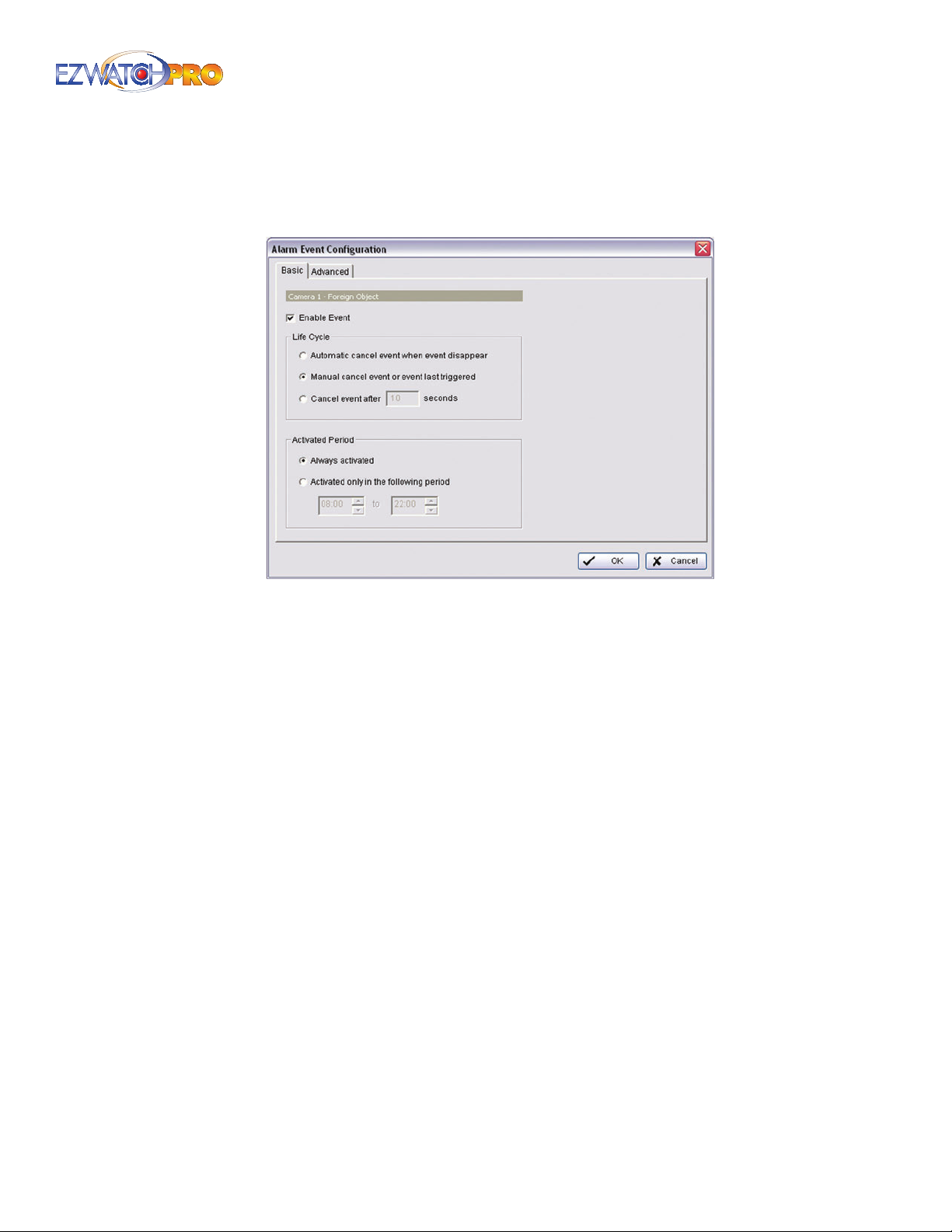
3.34 Event - Foreign Object
Alarm will be activated when an object appears in the dened area on the screen.
Fig. 109. Basic tab in Foreign Object Alarm Event
Conguration window
3.34.1 Basic Tab
Enable Event Check the box to activate.
Automatically cancel event when event disappear The alarm/action will be o once the
abnormality is xed or ends.
Manually cancel event or event last triggered The alarm/action will continue until being
canceled from the Main Console (Start>Open Event Report>Cancel All Events). The user currently
not watching the screen will be notied by the alarm.
Cancel event after time-out XX seconds Enable checkbox and setup the time-out seconds to
cancel the event after the time that you set whatever the events disappear or not.
Activated Period Assign the system to activate during a specied time period.
Page | 79 Software User Manual
Page 81
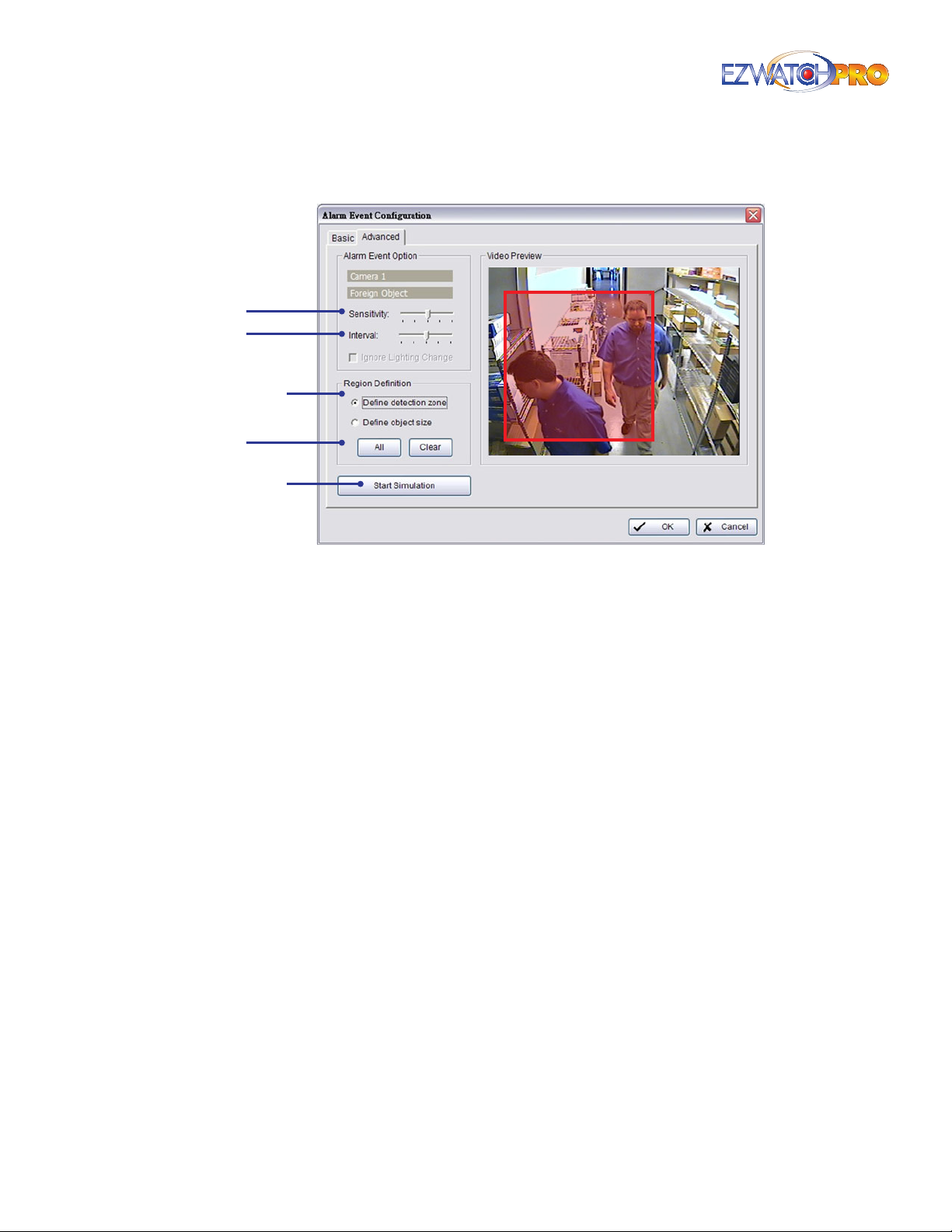
3.34.2 Advanced Tab
Sensitivity
Interval
Region
Denition
Dene
Object Size
Start
Simulation
Fig. 110. Advanced tab in Foreign Object Alarm Event
Conguration window
Sensitivity Click and move the slider to the right to increase sensitivity so that a relatively small
movement will trigger the alarm. Move the slider to the left to reduce the sensitivity of movement
detection. Establishing an appropriate Sensitivity value will reduce the chance of false alarm. For
example, you can lower the Sensitivity to avoid the alarm being triggered by a tree swinging in a
breeze.
Interval Click and move the slider to the right to increase the interval time so that the alarm will
only be triggered when the movement is of a longer duration. Move to the left to reduce the
interval time.
Region Denition To detect General Motion, you have to dene a detection zone. Left-click and
drag the mouse to draw a detection zone. You may dene more than one zone on the screen by
repeating the same process. User can also click on 'All' button to select the entire detection zone.
Dene Object Size After dening the detection zone, left-click and drag the mouse to indicate the
size of the object you want to detect.
Start Simulation Click the Start Simulation button and test the function on the preview screen.
80 | Page Software User Manual
Page 82
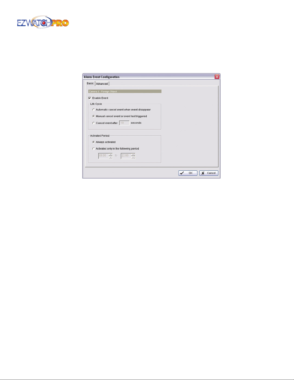
3.35 Event - Missing Object
Alarm will be activated when an object disappears in the dened area on the screen.
Fig. 111. Basic tab in Missing Object Alarm Event
Conguration window
3.35.1 Basic Tab
Enable Event Check the box to activate.
Automatically cancel event when event disappears The alarm/action will be o once the
abnormality is xed or ends.
Manually cancel event or event last triggered The alarm/action will continue until being
canceled from the Main Console (Start>Open Event Report>Cancel All Events). The user currently
not watching the screen will be notied by the alarm.
Cancel event after time-out XX seconds Enable checkbox and setup the time-out seconds to
cancel the event after the time that you set whatever the events disappear or not.
Activated Period Assign the system to activate during a specied time period.
Page | 81 Software User Manual
Page 83
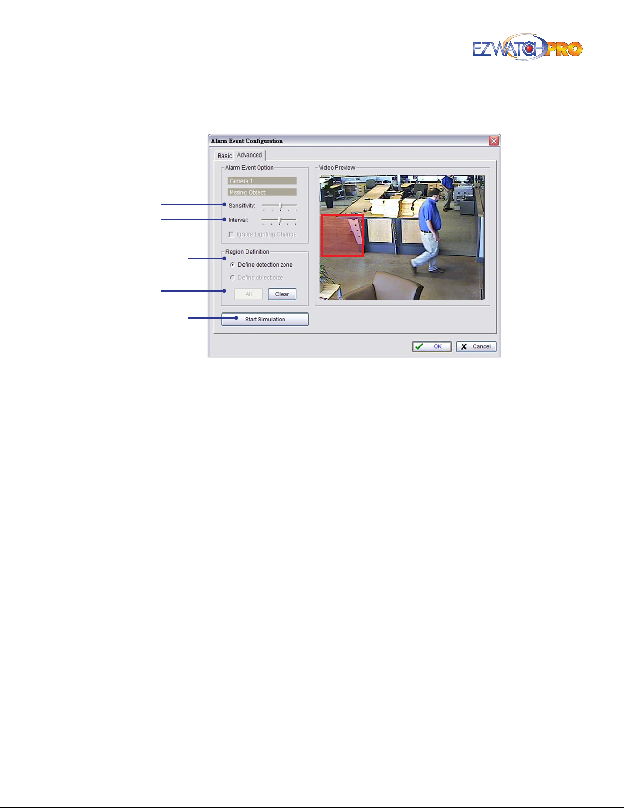
3.35.2 Advanced Tab
Sensitivity
Interval
Region
Denition
Dene
Object Size
Start
Simulation
Fig. 112. Advanced tab in Missing Object Alarm Event
Conguration window
Sensitivity Click and move the slider to the right to increase sensitivity so that a relatively small
movement will trigger the alarm. Move the slider to the left to reduce the sensitivity of movement
detection. Establishing an appropriate Sensitivity value will reduce the chance of false alarm. For
example, you can lower the Sensitivity to avoid the alarm being triggered by a tree swinging in a
breeze.
Interval Click and move the slider to the right to increase interval time so that the alarm will only
be triggered when the movement is of a longer duration. Move to the left to reduce the interval
time.
Region Denition To detect General Motion, you have to dene a detection zone. Left-click and
drag the mouse to draw a detection zone. You may dene more than one zone on the screen by
repeating the same process. User can also click on 'All' button to select the entire detection zone.
Dene Object Size After dening the detection zone, left-click and drag the mouse to indicate the
size of the object you want to detect.
Start Simulation Click the Start Simulation button and test the function on the preview screen.
82 | Page Software User Manual
Page 84
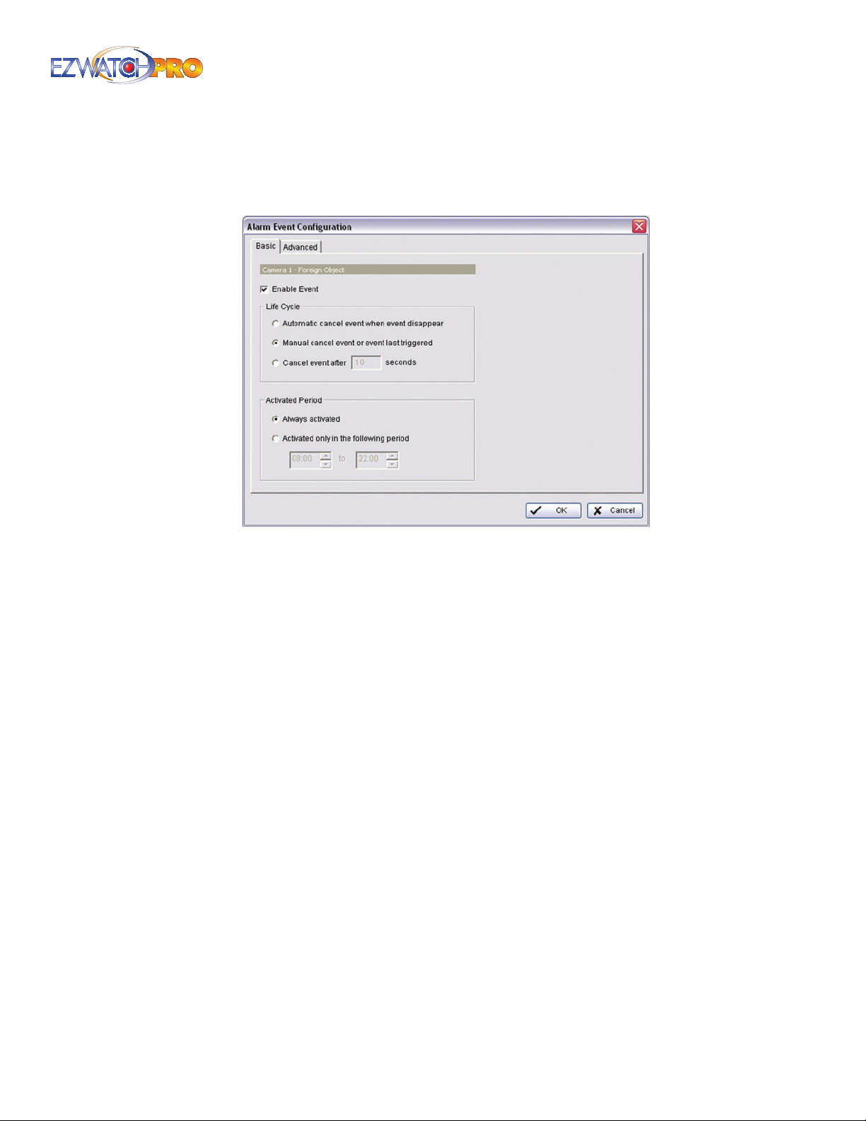
3.36 Event - Lose Focus
Alarm will be activated when any of the cameras loses focus or has a blurred image.
Fig. 113. Basic tab in Lose Focus Alarm Event Conguration
window
3.36.1 Basic Tab
Enable Event Check the box to activate.
Automatically cancel event when event disappear The alarm/action will be o once the
abnormality is xed or ends.
Manually cancel event or event last triggered The alarm/action will continue until being
canceled from the Main Console (Start>Open Event Report>Cancel All Events). The user currently
not watching the screen will be notied by the alarm.
Cancel event after time-out XX seconds Enable checkbox and setup the time-out seconds to
cancel the event after the time that you set whatever the events disappear or not.
Activated Period Assign the system to activate during a specied time period.
Page | 83 Software User Manual
Page 85
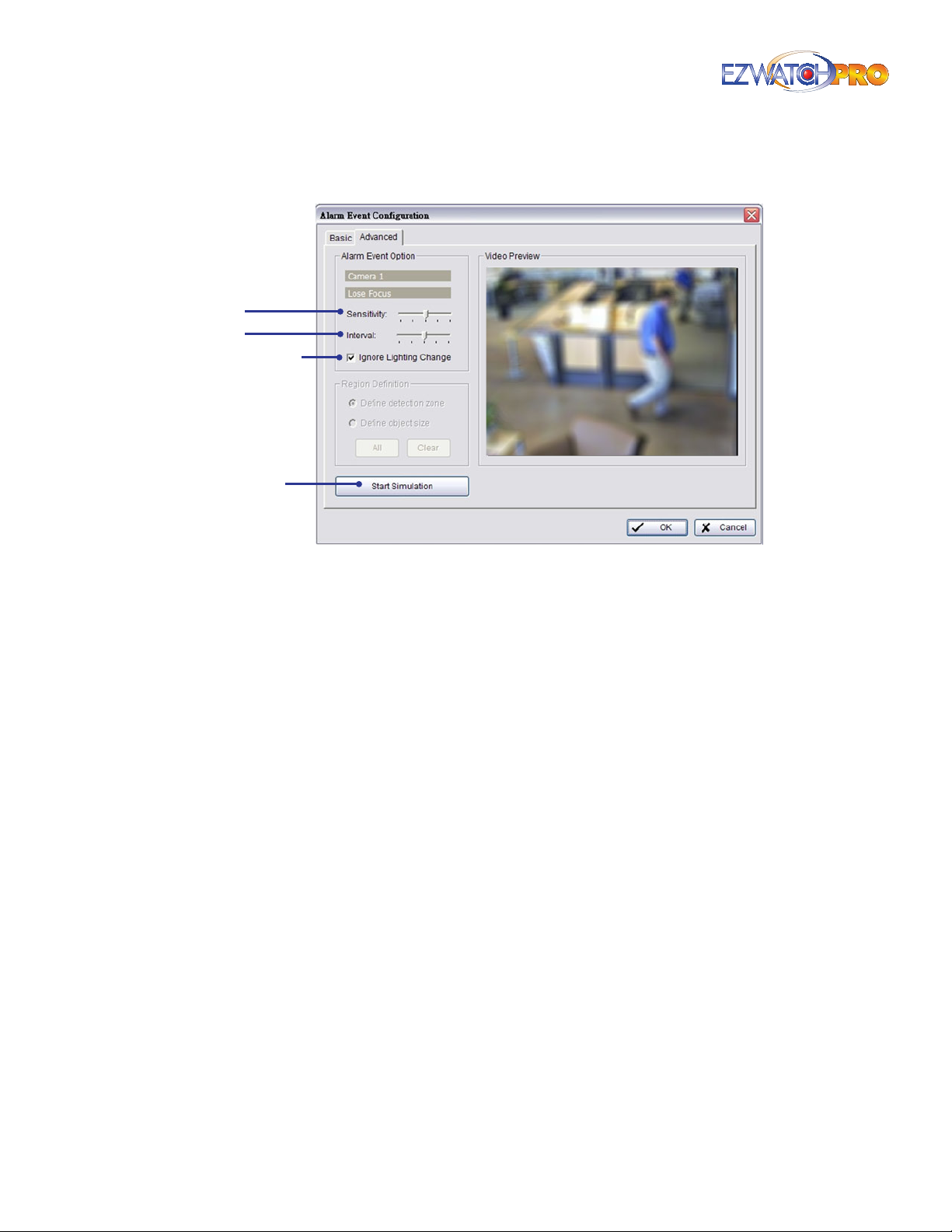
3.36.2 Advanced Tab
Sensitivity
Interval
Ignore
Lighting
Change
Start
Simulation
Fig. 114. Advanced tab in Lose Focus Alarm Event
Conguration window
Sensitivity Click and move the slider to the right to increase sensitivity so that a relatively small
movement will trigger the alarm. Move the slider to the left to reduce the sensitivity of movement
detection. Establishing an appropriate Sensitivity value will reduce the chance of false alarm. For
example, you can lower the Sensitivity to avoid the alarm being triggered by a tree swinging in a
breeze.
Interval Click and move the slider to the right to increase interval time so that the alarm will only
be triggered when the movement is of a longer duration. Move to the left to reduce the interval
time.
Ignore Lighting Check the box to avoid alarm being activated by changing light conditions.
Start Simulation Click the Start Simulation button and test the function on the preview screen.
84 | Page Software User Manual
Page 86
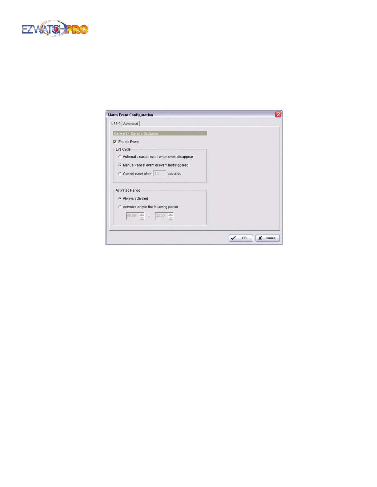
3.37 Event - Camera Occlusion
Alarm will be activated when any of the cameras view becomes obstructed by an object.
3.37.1 Basic Tab
Fig. 115. Basic tab in Camera Occlusion Alarm Event
Conguration window
Enable Event Check the box to activate.
Automatically cancel event when event disappear The alarm/action will be o once the
abnormality is xed or ends.
Manually cancel event or event last triggered The alarm/action will continue until being
canceled from the Main Console (Start>Open Event Report>Cancel All Events). The user currently
not watching the screen will be notied by the alarm.
Cancel event after time-out XX seconds Enable checkbox and setup the time-out seconds to
cancel the event after the time that you set whatever the events disappear or not.
Activated Period Assign the system to activate during a specied time period.
Page | 85 Software User Manual
Page 87
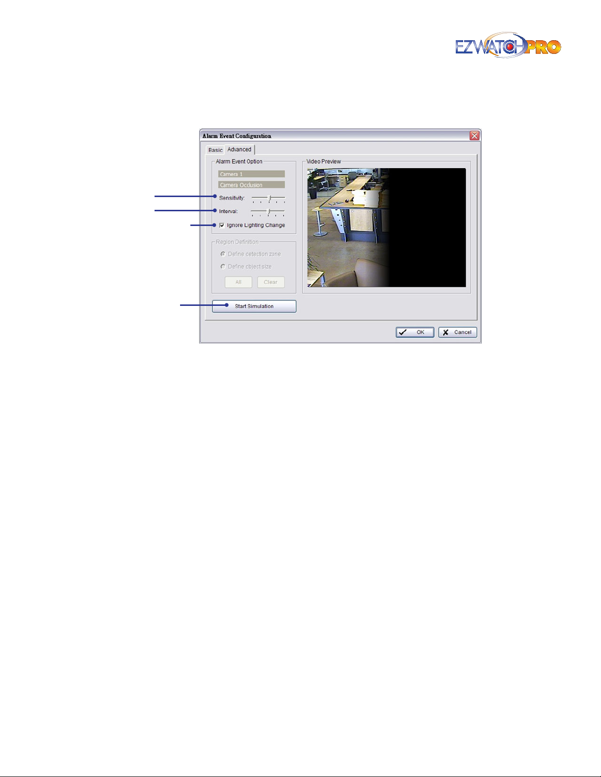
3.37.2 Advanced Tab
Sensitivity
Interval
Ignore
Lighting
Change
Start
Simulation
Fig. 116. Advanced tab in Camera Occlusion Alarm Event
Conguration window
Sensitivity Click and move the slider to the right to increase sensitivity so that a relatively small
movement will trigger the alarm. Move the slider to the left to reduce the sensitivity of movement
detection. Set up an appropriate Sensitivity value will reduce the chance of false alarm. For
example, you can lower the Sensitivity to avoid the alarm being triggered by a tree swinging in a
breeze.
Interval Click and move the slider to the right to increase interval time so that the alarm will only
be triggered when the movement is of a longer duration. Move to the left to reduce the interval
time.
Ignore Lighting Check the box to avoid alarm being activated by changing light conditions.
Start Simulation Click the Start Simulation button and test the function on the preview screen.
86 | Page Software User Manual
Page 88
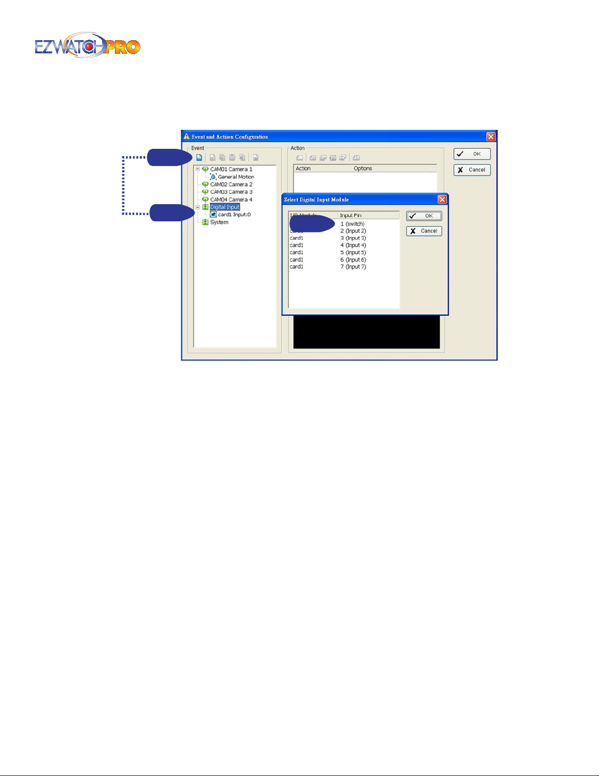
3.38 Event - Digital Input
Step 1
Step 1
Fig. 117. Select Digital Input Module above Event and Action
Conguration window
Step 2
■ Step 1 Click and highlight Digital Input on the event type list, and click the Insert Event icon.
■ Step 2 Select the input device connected to your PC.
The Digital Inputs are triggered from an external sensor, such as a wall-mounted Motion Detector
or a Door/Window sensor. There are only two states for any Digital Input: On or O. Because of this,
no advanced conguration is needed.
► Note To use Digital Inputs, you must have a TRP-C28 I/O Module and
a TRP-C08 Communication Module. These modules are not included
by default in EZWatch Pro kits and must be purchased separately. For
additional information you can read the I/O Module settings section of the
manual.
Page | 87 Software User Manual
Page 89
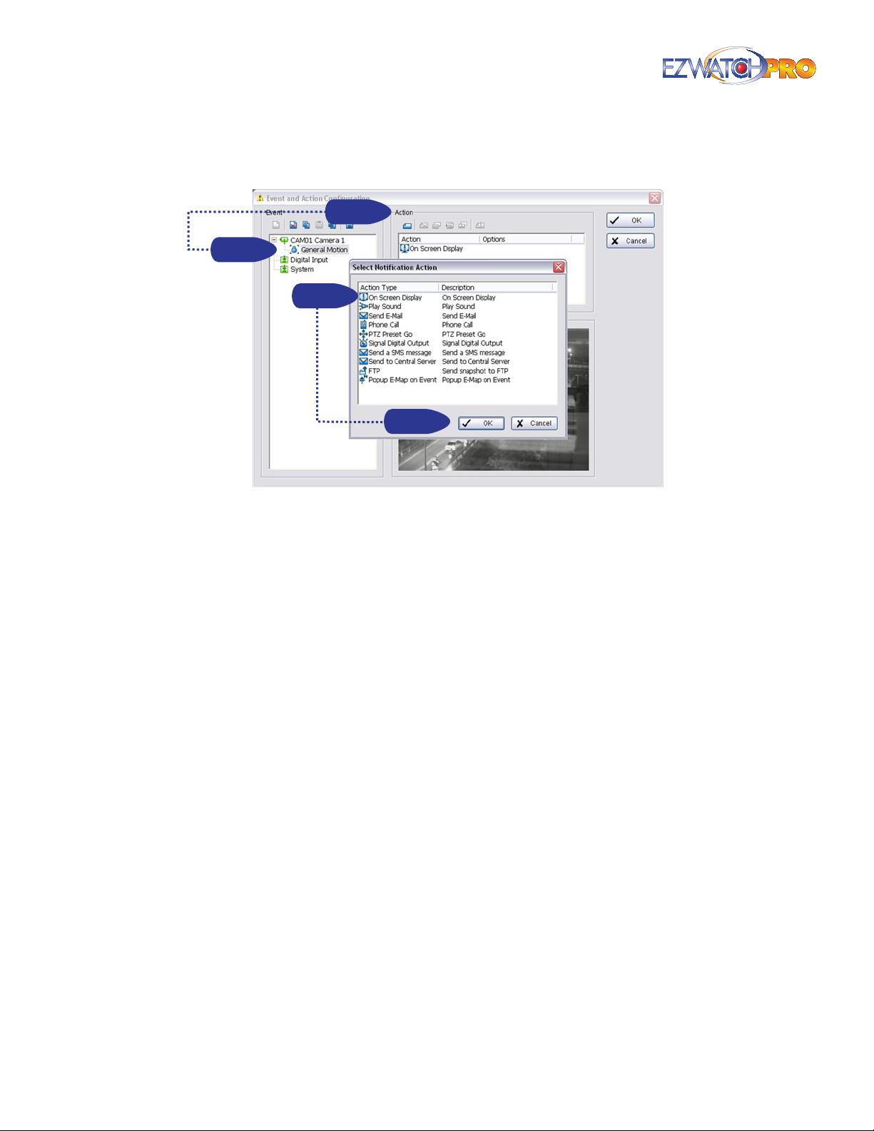
3.39 Action
Step 1
Step 1
Step 2
Step 2
Fig. 118. Insert Action procedure in Event and Action
Conguration window
Insert Action Setup actions responding to an unusual event.
■ Step 1 Choose an event and click the 'Insert Action' icon.
■ Step 2 There are 8 types of actions: On Screen Display (OSD), Play Sound, Send E-mail, Phone
Call, PTZ Preset Go, Signal Digital Output, Send a SMS Message, Send to Central Server, Send
snapshot to FTP, and Popup E-Map on event. Select the action you want from the list and then
click OK.
■ Step 3 Congure the setting of the Action Type, if needed.
3.39.1 Action Type
On Screen Display A red warning will ash on the screen of Main Console, indicating what type of
unusual event was detected.
Play Sound Sound alarm warning. Choose a Wave le (.wav) and the system will play the sound as
alarm when an unusual event is detected.
Send E-mail The system will send an E-mail immediately to given accounts indicating the type of
event, the time, and attaching a picture taken when the event was detected. To give the system
the E-mail accounts, go to Cong > Setup > Hotline. Refer to Hotline Conguration in 3.6.6
Hotline Conguration Tab on Pg. 38 for more details.
Phone Call The system will call a given phone number when an unusual event is detected. To
setup the phone number and make an audio record for the phone call, go to Cong > Setup >
Hotline. Refer to Hotline Conguration in 3.6.6 Hotline Conguration Tab on Pg. 38 for more
details.
PTZ Preset Go The PTZ (pan/tilt/zoom) camera will go to a preset point or auto patrol when an
unusual event is detected.
88 | Page Software User Manual
Page 90
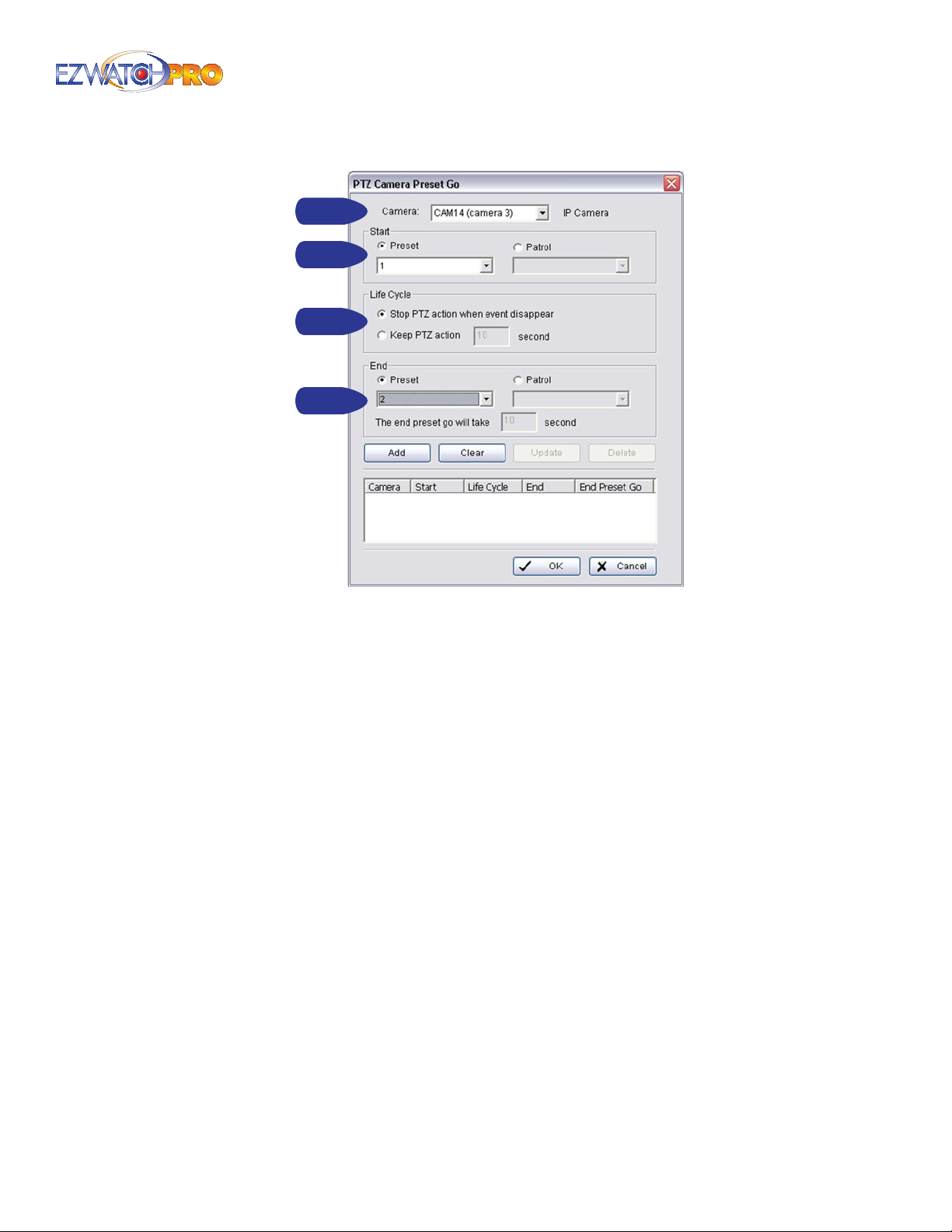
Step 1
Step 2
Step 3
Step 2
Fig. 119. PTZ Camera Preset Go window
Please follow the steps below to set up this function.
■ Step 1 Choose an event and click the 'Insert Action' icon.
■ Step 2 Select the 'PTZ Preset Go' action and then click OK.
■ Step 3 Set the action of cameras which you want to be trigger by events.
For example, set the action of camera 1:
Choose camera 1.
Set the start, end preset points.
•
Select the Life Cycle.
•
Click on Add.
•
Set the action of camera 2:
Choose camera 2.
Set the start patrol and end patrol.
•
Select the Life cycle
•
Click on Add.
•
Finally, click on OK to save all setting of cameras.
•
Page | 89 Software User Manual
Page 91
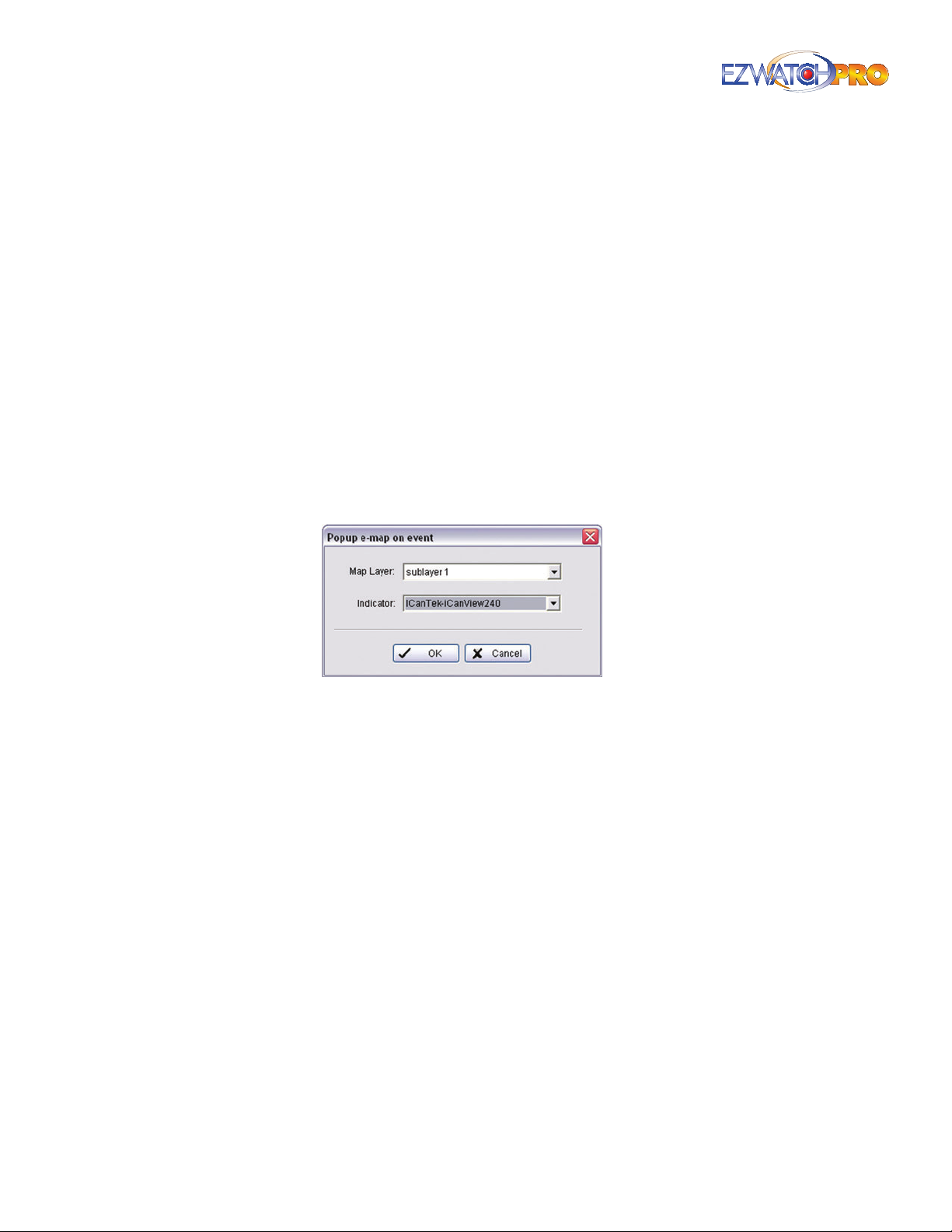
► Note You need to congure your PTZ camera before using this function.
Refer to 3.6.4 PTZ Conguration Tab on Pg. 35 for more details on PTZ
camera conguration.
Signal Digital Output Triggers traditional alarming devices connected to the system, such as
alarm lights and sirens.
Send an SMS message If the system has a GSM modem installed, the system will send an SMS
message immediately to specied accounts indicating the type and time of the event. To setup the
GSM modem, go to Cong > Setup > Hotline. Refer to 3.6.6 Hotline Conguration Tab on Pg. 38
for more details.
Send to Central Server The system will send an Event to Central Server. For more details, please
refer to the Central Management System user manual.
FTP The system will upload a snapshot immediately to an FTP site. To setup the FTP server, go to
Cong > Setup > Hotline. Refer to 3.6.6 Hotline Conguration Tab on Pg. 38 for more details.
Popup E-Map on Event The system will automatically pop up the E-Map window and show the
assigned map and indicator. To edit E-Map, refer to 3.2.1 Start Conguration on Pg. 23 for more
details.
Fig. 120. Popup E-Map on Event window
3.40 Remote Access Conguration
In a typical setup, there are some additional congurations that need to be made to your DVR (PC)
and/or your Network Router before you will be able to access your cameras from a remote location.
This guide will assist you in conguring security features. For information on conguring the Main
Console software for remote access, refer to 3.23 Remote Server on Pg. 67 for more details.
■ Step 1 It is recommended that you use the EZWatch IP service or a Static IP address before
attempting to remotely access your EZWatch Pro server. You can sign up for EZWatch IP at
www.ezwatchip.com or contact your ISP to obtain a Static IP address.
■ Step 2 Go to Start > All Programs > EZWatch Pro 4.0 > Main Console > Network Service.
■ Step 3 In the Network Service window, click on the Start button to begin streaming your
EZWatch Pro cameras live, thereby allowing users to log on to the server and view live streaming
cameras.
■ Step 4 You may still need to congure security features on your DVR in order to allow Remote
Access. By default, security applications such as anti-virus programs (Norton™, McAfee™), software
rewalls (Windows Firewall™, ZoneAlarm™), and hardware rewalls (Routers, Modems) are typically
defaulted to block remote connections similar to EZWatch Pro Remote Access.
90 | Page Software User Manual
Page 92

3.40.1 Anti-Virus Programs
Anti-Virus programs such as Norton Anti-Virus™ and McAfee Anti-Virus™ may need to be congured
in order for you to use the EZWatch Pro software applications. Please refer to the user manual of your
anti-virus program in order to determine how the EZWatch Pro software can be 'allowed' to work
in tandem with the anti-virus program. If a certain port number is requested, the default ports for
EZWatch Pro Remote Access are 5140, 5150, 5160, 80, and 8000.
3.40.2 Software Firewalls
Software rewalls such as Windows Firewall™ and ZoneAlarm™ may also need to be congured to
allow Remote Access. Typically, you will either need to 'allow' the EZWatch Pro software to be used or
you need to enter a port number similar to anti-virus programs or hardware rewalls. The default ports
for EZWatch Pro Remote Access are 80, 5140, 5150, and 5160. To setup Windows Firewall™, follow these
steps.
■ Step 1 Click on your Windows Start Button > Control Panel > Security Center > Windows Firewall.
■ Step 2 Click on the Exceptions tab at the top of the window.
■ Step 3 Click on Add Port.
■ Step 4 Enter EZWatch Pro as the Name, Enter 5150 as the Port, and select TCP. Repeat this step for
ports 80 and 8000.
■ Step 5 Click on 'OK' to submit the information and then exit the window.
3.40.3 Hardware Firewalls
Hardware equipment such as wireless routers and some modems have built in rewalls to help
prevent unwanted connections to your computer and network. In order to allow programs such as
Remote Access, you need to open ports in your hardware rewall as well. Opening these ports allow
certain types of data such as video and audio to transmit to the internet. This is commonly known as
Port Forwarding.
Port Forwarding can be one of the more involved tasks you’ll need to perform to be able to set your
PC up for remote viewing, but it doesn’t have to be dicult. When taken one step at a time, we can
very quickly and easily determine how your network is set up, and once that is known, then the Port
Forwarding itself is very straight-forward.
Port Forwarding is necessary because of routers. Routers are devices that split one connection up
amongst many computers. One single internet address can host thousands of computers using a
router. A problem arises when you have more than one router—splitting up a connection over and
over again. Conguring more than one router is dicult and does not normally work.
3.40.4 Is your modem a router?
Many modems have built-in routers, so our rst step is to determine if your modem is also a router.
This can be accomplished several ways: ask your Internet Service Provider (ISP), look up the modem
specication on the internet (the manufacturer’s product page should tell you), or look at the list of
routers located at http://www.portforward.com/ to see if your modem is listed there.
Page | 91 Software User Manual
Page 93
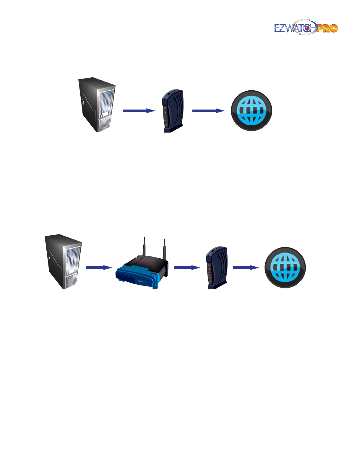
3.40.5 My modem is NOT a router
DVR
Fig. 121. DVR to Modem to Internet conguration
If your modem is not a router, look at how your computer is connected to the modem. If your
computer is connected directly from the modem to the PC, then you do not have a router. Your
connection is not being split up, and you do not need to do any Port Forwarding. This is the easiest
setup, but these days a setup like this is usually rare.
If your modem is not a router, but you have your computer connected to a separate router, then you
need to congure Port Forwarding on your router. Refer to 3.40.7 Setting up Port Forwarding on Pg.
93 to set up Port Forwarding.
Modem Internet
3.40.6 My modem IS a router
DVR
Router
Fig. 122. DVR to Router to Modem to Internet conguration
Modem Internet
If your modem is a router, then you need to determine if it is the only router present. If you have
more than one router, then you will need to bypass all but one of them. The rst step is determining
whether or not there is a second router present. Follow the cable from your computer. Does it connect
directly into the modem? If this is the case, then you only have one router (the modem). You will need
to congure Port Forwarding on that modem as detailed in 3.40.7 Setting up Port Forwarding on
Pg. 93.
If your computer is connected to another device between it and the modem, then you need to
determine what kind of device it is. Hubs and Switches do not split up connections like routers do
(they only split up cables), and do not require any Port Forwarding. But if you have a router between
the computer and the modem, this means you have two routers present, and that creates a problem.
You will need to bypass the second router, or you need to turn o the router inside of the modem.
Turning o a router is done by setting the modem to Bridging mode. This cannot be done on all
routers, and to do this you should contact your ISP. Ask them if they can help you set the modem into
Bridging mode. Once the modem is in Bridging mode, you only have one router, and need to set up
Port Forwarding, as detailed in 3.40.7 Setting up Port Forwarding on Pg. 93.
92 | Page Software User Manual
Page 94
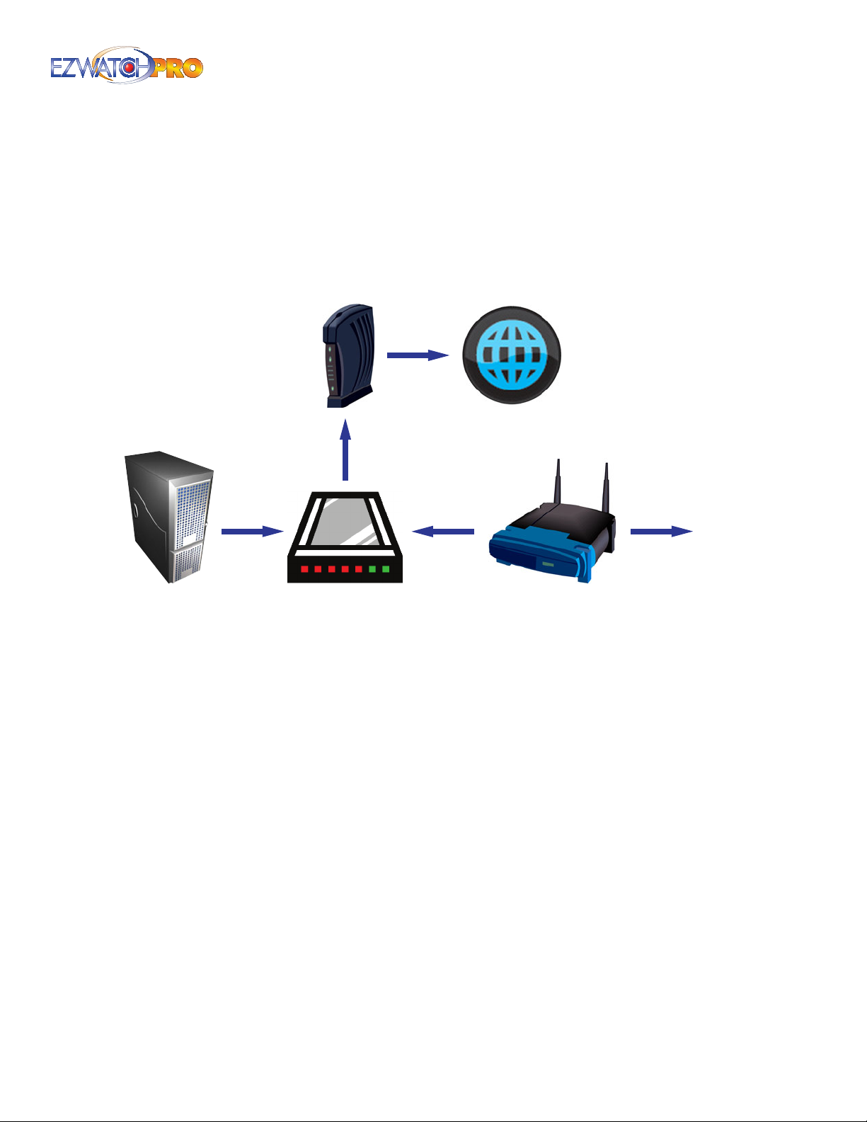
If you cannot set your modem to Bridging mode, then you need to bypass the router. Typically this
is done by plugging the computer directly into the back of the modem. If there are not enough jacks
to plug the computer directly into the modem, use a hub or switch to increase the number of jacks
present. Run a cable from the modem into a hub, then run a cable from the hub to your computer. If
you still need the router then you can also plug the router into the hub—just do not plug the DVR into
the router. Now that the router has been bypassed, set up port forwarding on the modem, as detailed
in 3.40.7 Setting up Port Forwarding on Pg. 93.
Modem
DVR
Fig. 123. DVR to Hub/Switch conguration
Hub/Switch
3.40.7 Setting up Port Forwarding
Internet
Network
Router
Your router must be congured for Port Forwarding in order for a user to view your DVR from a remote
location. If there are many computers within a network, a router is used to help split the connection
to the internet. If a router does not know which PC is the recipient of a connection request, the router
discards the request. Port Forwarding forces a router to send the connection request to a specic
computer—in our case, the DVR.
3.40.7.1 Business Connections
If you have a business internet connection, you will want to contact your ISP and determine if they
must set up the Port Forwarding for you. Many business connections use special modems that cannot
be congured by the user. If this is the case, you must contact your ISP and ask them to set up port
forwarding on the following ports: Port 80 (if Port 80 cannot be used, we recommend port 8000), Port
5140, Port 5150, and Port 5160.
► Note It is not enough merely to 'Open' a port. If a port is 'Open,' then your
connection request will not be blocked, but forwarding is STILL required to
tell the router which computer to send the connection request. Many ISPs
may misunderstand this and only 'Open' the port, and because forwarding
is not set up, you still will be unable to connect. Please make certain the ISP
has actually forwarded, and not just opened, your ports.
Page | 93 Software User Manual
Page 95

3.40.7.2 Personal Connection
If you are using a router, you need to obtain the Make and Model number of the unit. For more
information on conguring Port Forwarding, please refer to the user manual of your router or follow
the steps for assistance in setting up Port Forwarding on your router or modem.
■ Step 1 Open a web browser such as Internet Explorer or Mozilla Firefox. Go to the web address
www.portforward.com.
■ Step 2 From the home page, there is a list of routers/modems sorted by Make and Model. Locate
your device in the list.
► Note If your router or modem is not listed here, you will need to refer to the
User Manual for instructions on conguring Port Forward. You may also be
able to contact the manufacturer of the device or your ISP if they provided
the router/modem for you.
■ Step 3 Once you have located your router/modem, the next page will ask you to select the
program for which you are forwarding ports. EZWatch Pro will not appear in this list of programs.
► Note You need to use the Default Guide to set up Port Forwarding for
EZWatch Pro.
■ Step 4 Follow the step-by-step instructions provided in the following pages to set up Port
Forwarding for your specic router/modem. The default ports for EZWatch Pro Remote Access are
Port 80, Port 5140, Port 5150, and Port 5160. You will need to enter each one of these ports.
► Note www.portforward.com will not set up port forwarding for you. It
simply provides step-by-step instructions on setting up port forwarding
on your router/modem. You will need to access your router/modem
conguration using your Internet Explorer browser in order to add the
ports.
3.41 Remote Access Connection
Now that you have congured your DVR and Network for remote access, you are now ready to connect
to your cameras from a remote location using the Remote Live Viewer software or Internet Explorer.
The instructions on the next page are to be used at the remote location.
3.41.1 Installing the Remote Live Viewer
■ Step 1 Insert the Software CD.
■ Step 2 The EZWatch Pro installation disc should run automatically. If not, click on the My
Computer icon and locate the EZWatch Pro software disc under 'Devices with Removable Storage'.
Open the disc by double-clicking on the icon. Locate the 'Setup.exe' le to begin installing the
EZWatch Pro Software.
■ Step 3 Follow the Windows Installation Wizard.
Complete/Custom Setup Type:
You may install the system to a preferred directory and choose which feature(s) you want to install
to the PC (Custom setup is recommended).
Uncheck Main Console and make sure Playback and Remote Live Viewer is checked.
94 | Page Software User Manual
Page 96
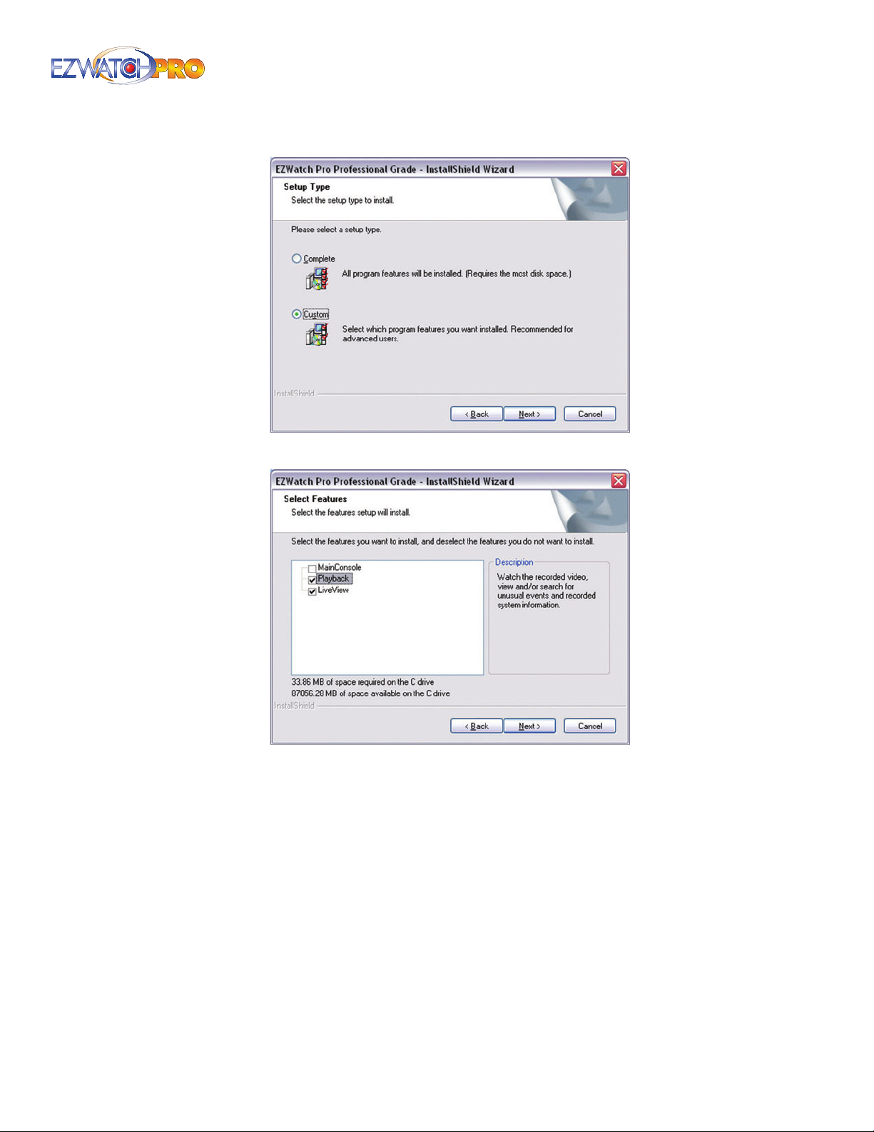
Fig. 124. EZWatch Pro InstallShield Wizard for Custom Install
Fig. 125. Custom Installation of Playback and LiveView
■ Step 4 Restart your PC.
► Note If you do not have your installation disc available, you
can download the EZWatch Pro software from our website, at:
http://www.ezwatch-security-cameras.com/downloads/
Page | 95 Software User Manual
Page 97
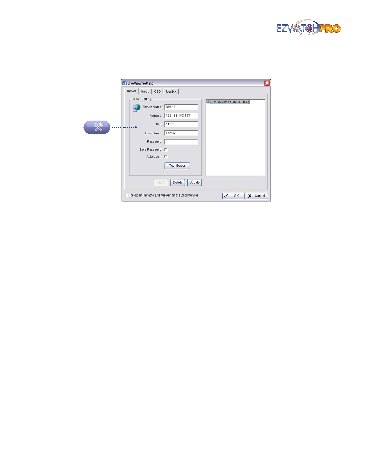
3.42 LiveView Setting (Site Setup)
Fig. 126. Server tab in LiveView Setting window
3.42.1 Server Tab
With the Remote Live Viewer console, remote users may watch real-time video from remote live
streaming servers.
■ Step 1 Go to Start > All Programs > EZWatch Pro 4.0 > Remote Live Viewer.
■ Step 2 Click on the Site Setup button.
■ Step 3 Enter the Server Name, your EZWatch IP or Static IP Address, Port 5150 and then click the
Add button.
■ Step 4 Click 'OK' to close the Site Setup window.
■ Step 5 Now click on the new Server listed on the Remote Live Viewer console. Then click the
Login button.
Enter the Username and Password if needed.
■ Step 6 Now choose the cameras you would like to view remotely.
96 | Page Software User Manual
Page 98
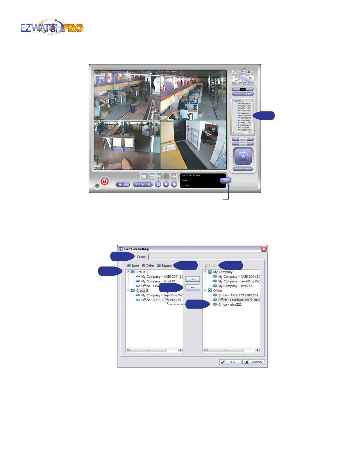
Site Setup
Fig. 127. EZWatch Pro console
3.42.2 Group Tab
You may create custom camera groups from multiple servers.
Step 1
Step 3
Step 6
Step 2Step 5
Step 4
Step 4
Fig. 128. Group tab in LiveView Setting window
■ Step 1 Go to the Group tab of the LiveView Setting window.
■ Step 2 Log in to all the servers that contain the camera(s) you would like to put into the group(s).
■ Step 3 Click 'Insert' to create a new group. Name the group for future reference.
Page | 97 Software User Manual
Page 99
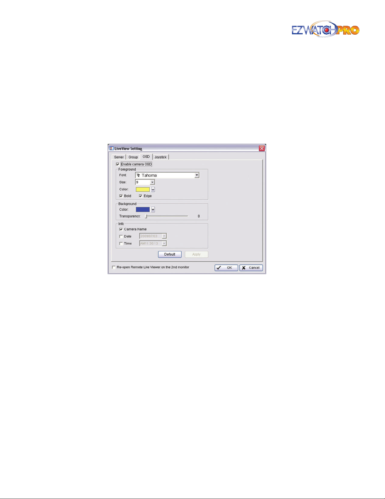
■ Step 4 From the window at the right, highlight the camera(s) you would like to add to a group
and then click on the '<--' button. Repeat the process until you are satised with the group setting.
■ Step 5 Click on the Delete and Rename button to remove or rename a specic group.
■ Step 6 Repeat Step 3 to 5 until you are done with creating and setting groups.
■ Step 7 Click 'OK' to save settings.
3.43 On Screen Display (OSD) Tab
Fig. 129. On Window Display (OSD) tab in LiveView Setting
Enable Camera OSD Display video information on the live video feed. The information includes
camera name, camera number, date, and time. User may also set up OSD font, including font, font
size, font color, and any desired font eects.
window
3.44 Joystick Tab
This feature supports the previous joystick controller used for PTZ and IP cameras. Using the TRP-C08
module, this conguration is no longer necessary for current joystick controllers.
98 | Page Software User Manual
Page 100
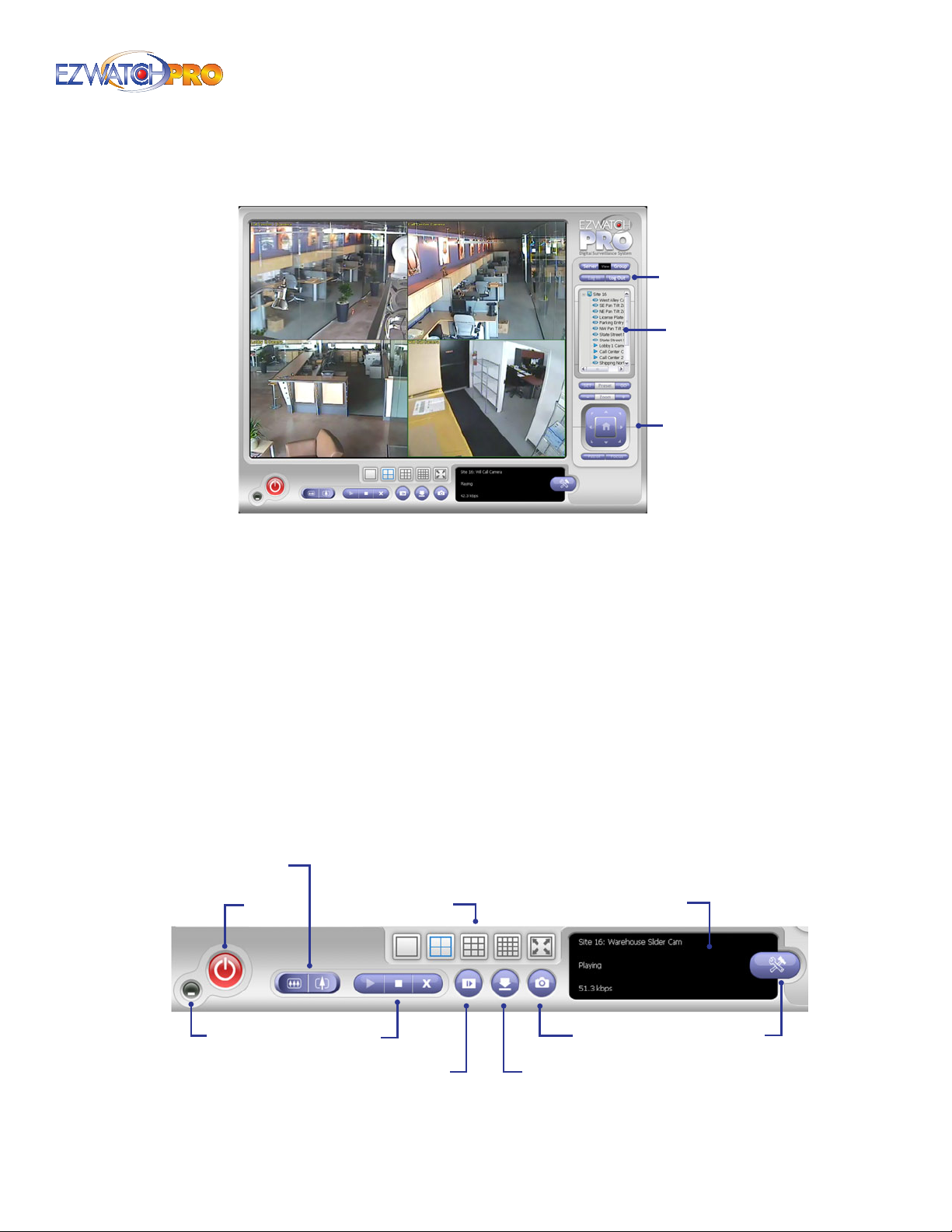
3.45 Remote Live Viewer Console
Log In/Out
Camera
List
PTZ
Camera
Control
Fig. 130. Camera List in EZWatch Pro console
Select a camera(s) from the server/camera list on the right and then drag it to where you want the
image to be displayed.
On the server/camera list, right click on a camera to connect/disconnect it.
Log In/Log Out Select a server or a group and click on the Log In/Log Out button to access/leave
the server. You may also log in/out from the server by right clicking on it.
Server and Camera List Display a complete list of the server(s) and camera(s) that are added to
the system.
PTZ Camera Control You may control the camera view by utilizing the PTZ camera control panel
to adjust the camera’s view. This is only available with cameras that support PTZ function.
► Note The PTZ Camera Control buttons function identically to the PTZ
Camera Controls in the Main Console. For additional details on how to use
these features, see 3.6.5 Main Console PTZ Control Panel on Pg. 37.
Digital Zoom
Exit
Minimize
Screen Division
Play/Stop/Drop
Playback
Fig. 131. Remote LiveView Console controls
Information Display
Snapshot
Remote I/O
Site Setup
Page | 99 Software User Manual
 Loading...