

Page 1
Page 2

2
Table of Contents
About This Guide ------------------------------------------------------------------------------ 6
FCC Compliance Statement ------------------------------------------------------------- 6
FCC Warning -------------------------------------------------------------------------------------- 6
License Agreement --------------------------------------------------------------------------- 7
Software Product License ----------------------------------------------------------- 7
Upgrades: -------------------------------------------------------------------------------- 8
Trademark ----------------------------------------------------------------------------------------- 9
Customer Support ---------------------------------------------------------------------------- 9
Chapter 1 Product Introduction ----------------------------------------------------- 10
1-1. Product Features --------------------------------------------------------------- 10
Chapter 2 Software Installation ---------------------------------------------------- 16
2-1. Software System Requirements -------------------------------------- 16
2-1-1. EZWatch Pro --------------------------------------------------------------- 16
2-1-2. EZNetwork and EZModem ---------------------------------------- 17
2-2. Installation Prerequisites ------------------------------------------------- 18
2-3. Installing EZWatch Pro 3.1 HD Software ------------------------ 18
2-4. Video Board and Driver Installation -------------------------------- 24
2-5. Setup Windows XP to run EZWatch Pro 3.1 HD ------------- 26
2-6. Software Installation Procedures ------------------------------------ 28
2-6-1. EZNetwork Installation Procedures (TCP/IP) ------- 28
2-6-2. EZModem Installation Procedures -------------------------- 29
2-6-3. PDAView Pro Installation Procedures --------------------- 31
Chapter 3 System Configuration ---------------------------------------------------- 32
3-1. EZWatch Pro Functions Overview ------------------------------------ 32
3-2. How to Prevent System Crashes -------------------------------------- 33
3-2-1. Power Management Setup --------------------------------------- 34
3-2-2. Windows File System Setup ------------------------------------- 34
3-2-3. How to setup System Reboot Schedule ------------------ 34
Page 3
3
3-3. EZWatch Pro System Configuration -------------------------------- 36
3-3-1. Set up video Parameters-EzSetup --------------------------- 36
Chapter 4 EZWatch Pro System Operation ----------------------------------- 40
4-1. Surveillance Server Program -------------------------------------------- 40
How to change the video parameters? ------------------------------- 42
4-1-1. How to Login to EZWatch Pro ------------------------------- 44
4-1-2. Camera Configuration -------------------------------------------- 44
4-1-2-1. General -------------------------------------------------------- 44
4-1-2-2. Recording ---------------------------------------------------- 45
4-1-2-2-1. Set up the recording schedule -- 46
4-1-2-3. Motion Setting -------------------------------------------- 58
4-1-2-4. Video Loss --------------------------------------------------- 61
4-1-2-5. POS & FingerKey (Optional) -------------------- 62
4-1-3. EzSyncPlayback ----------------------------------------------------- 65
4-1-4. Playback Video Clips ---------------------------------------------- 71
4-1-5. Network Configuration ------------------------------------------ 73
4-1-6. System Configuration/EzTools ----------------------------- 75
4-1-7. Setup Privileges ------------------------------------------------------ 80
4-1-8. View Log ------------------------------------------------------------------ 81
4-1-9. Setup I/O ---------------------------------------------------------------- 82
a.) Setup relay (Optional) ----------------------- 83
b.) Control NetCom Module relay (Optional) -- 84
c.) Setup NetCom Module sensor (Optional) - 84
d.) Emergency call ------------------------------- 85
e.) Fingerprint Access Control ------------------ 86
4-1-10. Storage Device Configuration ------------------------------ 86
4-1-11. Video Control Panel ------------------------------------------------------ 88
4-2. Back up system-EzBackup ----------------------------------------- 91
4-3. Web Browse Server – EzWebServer -------------------------- 93
Page 4

4
4-4. LAN Play Back Video Clips – EzLanPlayback ------------ 97
4-5. Play Back Video Clips – EzPlayback ------------------------- 100
4-6. Text insert Playback – EzTextPlayback ------------------- 102
4-7. Remote Control Server– EzRServer ------------------------ 102
4-8. Two Way Communication – EzSTalk ----------------------- 103
4-9. Access Control – EzFingerKey ----------------------------------- 105
4-10.Uninstalling EZWatch Pro Software and Device Driver105
4-10-1. Uninstalling EZWatch Pro ------------------------------------- 105
4-10-2.Checking for or Uninstalling the Device Driver --- 106
Chapter 5 Remote Client PC Software ---------------------------------------- 110
5-1. How to use the Remote Client program ------------------------ 110
5-1-1. How to use EZNetwork ------------------------------------------- 110
5-1-2. How to use EZModem ---------------------------------------------- 111
5-1-3. Free View Pro/EZModem Program Operation------ 113
5-1-4. Connecting to Local DVR SEVER ---------------------------- 115
5-1-5. Video Window Function Description --------------------- 118
5-1-6. Using the Site Book ------------------------------------------------- 121
5-1-7. System Configuration ---------------------------------------------- 122
5-1-8. Playing Back Video Clips ----------------------------------------- 123
5-1-9. Remote Download Video Clips ------------------------------- 126
5-1-10. Remote Setting the parameters of EZWatch Pro127
Chapter 6 Remote Client PDAView Software ----------------------------- 129
6-1. PDAView Program Operation ----------------------------------------- 129
6-2. Connecting to DVR site --------------------------------------------------- 130
6-3. Using the Site Book --------------------------------------------------------- 131
Chapter 7 EZWatch IP How-To ---------------------------------------------------- 132
7-1. How to remotely view security cameras ----------------------- 132
7-2. Setting up Internet Access using EZWatch IP ------------- 135
7-3. Configuring your DVR for Remote Access --------------------- 136
Page 5

5
7-4. How to Make a Twist-on BNC Video Cable Fitting-------- 145
7-5. How to wire a Multi-camera Power Supply ------------------ 146
7-6. How to Setup a Pan/Tilt/Zoom (PTZ) Camera ------------ 147
7-7. How to Setup PDA Remote Viewing ------------------------------ 152
7-8. How to burn Video Clips to a CD/DVD -------------------------- 154
7-9. How to Setup Audio Recording -------------------------------------- 155
Appendix A: Optimum CPU for Each DVR Board ------------------------ 157
Appendix B: DVR Board System Requirements ------------------------- 158
Page 6
6
About This Guide
Conventions used in this guide
To make sure that you perform certain tasks properly, take note of the following
symbols to use throughout this manual.
WARNING: Information to prevent injury to yourself when trying to
complete a task.
CAUTION: Information to prevent damage to the components when trying
to complete a task.
IMPORTANT: Information that you must follow to complete a task.
NOTE: Tips and additional information to aid in completing a task.
FCC Compliance Statement
This device complies with part 15 of the FCC Rules. Operation is subject to the
following two conditions: This device may not cause harmful interference, and
this device must accept any interference received, including interference that
may cause undesired operation.
FCC Warning
This equipment has been tested and found to comply with the limits for a Class B
digital device, pursuant to Part 15 of the FCC Rules. These limits are designed to
provide reasonable protection against harmful interference in a residential
installation. This equipment generates uses and can radiate radio frequency
energy and, if not installed and used in accordance with the instructions, may
cause harmful interference to radio communications. However, there is no
guarantee that interference will not occur in a particular installation. If this
equipment does cause harmful interference to radio or television reception, which
Page 7

7
can be determined by turning the equipment off and on, the user is encouraged to
try to correct the interference by one or more of the following measures:
Reorient or relocate the receiving antenna.
Increase the separation between the equipment and receiver.
Connect the equipment into an outlet on a circuit different from that to
which the receiver is connected.
Consult the dealer or an experienced radio/TV technician for help.
Shielded cables and I/O cords must be used for this equipment to comply
with relevant FCC regulations.
License Agreement
----------------------------------------------------------------------------------------Important-Read Carefully: This EZWatch Pro Software License is a legal
agreement between you (either an individual or an entity) and Automated Video
Systems LLC for the EZWatch Pro products. By installing, copying, downloading,
accessing or otherwise using the product, you agree to be bound by the terms of
this document. If you do not agree to the terms of this agreement, do not install
or use the product; you may however, return it to your place of purchase for a
refund.
-----------------------------------------------------------------------------------------
Software Product License
Grant of License:
The software license is granted, not sold to dealers or end users. No one is
granted the right to copy the software or user manuals. All software must be
ordered from EZWatch Pro.
Other rights and limitations:
This document does not give any end user or dealer any rights in connection with
any trademarks or service marks of EZWatch Pro. The manufacturer will provide
technical support to all end users and all dealers with conditions. It is the end user
or d e a ler’s resp o nsib ility to verify tha t the com pu ters they p rovide m eet th e
systems requirements. The company reserves the right to suspend support until
Page 8

8
the customer can provide documentation that the computer being used does in
fact meet all requirements.
Termination:
EZWatch Pro and AVS reserves the right to terminate this agreement with any
end user or dealer who the company deems has acted illegally or in any deceptive
or less than ethical manor. The customer will be refunded the original cost of the
kit, with proof of sale, if the company exercises this right.
Upgrades:
The customer and all dealers will retain the right to up-grade their software to the
latest version offered at no cost other than shipping fees as long as there are no
required hardware upgrades for the software to operate. If additional hardware or
hardware up-grades are required it will be the responsibility of the user or dealer
to pay for, and provide the equipment.
Infringement & Copyright:
The manufacturer reserves all rights of product and software protection allowed
under U.S. law. No user or dealer will attempt to copy, manipulate, steel or
de-encode any part of the software, firmware or hardware. Any such intentional
actions will void all rights granted with this agreement.
Limits of Liability
AVS, the manufacturer of the EZWatch Pro system warrantees the system to be
free from design and programming errors. However, the system requires several
pieces of equipment which are not manufactured by AVS i.e.: (Operating Systems,
Motherboards, Processors, RAM, Hard drives etc). There are thousands of
possible system configurations, some more reliable than others. Because of this,
AVS will not accept any type of responsibility for system performance or liability
caused by a system malfunction or nonperformance. Nor will AVS be held
responsible for any data corruption or data loss due to the installation or use of
our products. By installing or using any AVS products you are releasing AVS from
any type of liability and surrendering all rights of recourse for nonperformance
other than a refund. If you are not willing to accept these terms and agree that
AVS will not be held liable for any reason, do not install or use the system. Return
the product to the place of purchase for a refund.
For further information call toll free
1-866-241-3400 or write to:
Page 9

9
Automated Video Systems, LLC.
1470 South 600 West
Woods Cross, Utah 84010
Trademark
EZWatch Pro, EZNetwork and EZModem are registered trademarks of Automated
Video Systems.
Microsoft Windows 2000 and XP are registered trademarks of Microsoft
Corporation. All other trademarks are the property of their respective holders.
Customer Support
If problems arise with the remote surveillance and security system that you are
unable to resolve, call us at Tel: 866-241-3400 Fax: 801-295-2191. We are
dedicated to providing the highest quality support. You may also email us at
[email protected]
Page 10

10
Chapter 1 Product Introduction
Introducing the most advanced, high performance PC based video surveillance
system on the market. EZWatch Pro 3.1 is packed with advanced features, yet is
surprisingly easy to use. Version 3.1 out performs the most expensive video
systems at a fraction of their cost. Available direct from the factory and supported
by trained, experienced factory technicians.
1-1. Product Features
The EZWatch Pro surveillance software provides following
features:
Feature Details
EZWatch 3.1 HD is available as complete Digital Video Recorders (DVR) in 4, 8,
12, 16 and 32 camera configurations or as Kits that install on a PC you provide.
Either way you have the most advanced video surveillance system available....at
a great price.
High-Definition Recording
EZWatch 3.1 software allows you to set different recording resolutions for each
security camera. The resolution of a video image is defined by the number
horizontal and vertical pixels used to create it. Our DVR software allows you to
choose which resolution you prefer for each camera… standard resolution
(320x240 & 352x240) or high resolution (640x480 & 720x480.)
Live Video Viewing
EZWatch Pro 3.1 HD is offered in two versions. Business Grade which provides
7.5 frames per second live viewing per camera and Professional Grade which
provides 30 frames per second live viewing per camera.
Custom Recording Speeds
Each security camera can be set to record at one of fifteen different speeds or
frame rates referred to as Frames per Second (fps). You can choose from 1/3
frame per second all the way to 15 frames per second, which produces the
equivalent of live video surveillance recording.
30-60 Days of Video Storage
Our high performance video compression allows you to store thirty to sixty days
of video for each security camera on a standard PC hard drive. The video is
Page 11

11
recorded in MPEG 4 format and produces an average file size of 1.5kb per frame
for standard resolution recording and an average file size of 7.1kb per frame for
high definition recording.
Video Playback on ANY Windows PC
Our video is recorded with a Windows compatible codec. This allows the video
clips to be transferred to any PC and played back with windows media player. No
custom playback software is required.
Custom User Settings and Passwords
Each user can be assigned their own login name and password. During user set
up each user is assigned the specific system functions and security cameras they
will have access to. If a user is not assigned specific surveillance cameras, those
cameras are never displayed for that user. Whether a user is accessing the
surveillance system from the main PC or remotely, the user’s abilities are always
limited to their user settings.
Multi Camera Viewing and Auto Rotation
The system allows you to choose any combination of surveillance cameras to be
view on the screen at any one time and then automatically rotate to a new
screen with another set of specifically chosen surveillance cameras. Any
combination of cameras can be viewed in the following formats 4, 6, 8, 13, 16,
22 and 25. Any camera can be called to full screen by simply clicking on the
video feed with the mouse.
Motion Detection Recording and Alarm
Each security camera can be set to start recording its video surveillance feed and
launch a video alarm to a remote PC, PDA or CCTV monitor when motion is
detected. Each camera can be programmed to only record in motion detection
mode during a custom time period and you can choose which areas of the
cameras view triggers the motion alarm. The system monitors the pixels being
received from the security camera and can detect a change in the pixel pattern
which occurs when there is movement in the viewing area.
Automatic Email Alarm Notification
Any video surveillance camera can be programmed to send a custom email
when a defined alarm occurs such as motion detected. The email can detail the
type of alarm, the camera that generated it and attached an image file.
Page 12

12
Automatic Recording Schedules
Each surveillance camera can be independently programmed to automatically
record on predetermined time periods. You can choose between continuous
recording, motion activated recording, or any combination of the two during a
day, a week or any custom time period.
Multi- Camera Playback
With the EZWatch Pro 3.1 Video Player any combination of surveillance cameras
can be played back simultaneously. The controls include: Play, Pause, Stop,
Zoom In, Zoom Out, Copy Video to CD, Previous Frame, Next frame, First
Frame, Last Frame, Repeat, Delete, Manual Review Slide Bar, Snap Shot,
Resize, Next Video, Previous Video, Slow Frame Rate, Increase Frame Rate,
Adjust Screen Size, Quick Search.
Pan, Tilt and Zoom Camera Controls
The system provides complete control of PTZ security cameras on-site as well as
remotely via dial-up, the internet or even PDA's. The security cameras can be
programmed for auto scanning and pre-set positioning. When an alarm occurs a
camera can be programmed to pan, tilt and zoom to a predetermined location or
view. Panning, tilting and zooming a camera is quick and easy with our graphic
interface.
Audio Monitoring and Recording
Each system can record one channel of audio. The microphone is attached to the
microphone input on the PC. The software allows you to attach the audio feed to
any one of the security cameras being recorded. The result is clear, high quality
audio/video recordings. The audio can be monitored live on-site or remotely.
Operates on...
EZWatch 3.1 HD will operate reliably on any of the following platforms assuming
the PC meets the listed requirements. Windows 2000, XP Home & XP Pro.
Pre-Alarm Recording
This feature allows you set the system to actually record the video of any
selected security camera 5 seconds before an alarm occurs. The system
constantly buffers 5 seconds of the video feed. When an alarm occurs the
system attaches the buffered video to the video being recorded.
Page 13

13
Remote Access
The digital video recorder system can be accessed via dial-up, company
network, internet (cable or DSL) with dynamic or static IP addresses as well as
PDA's. All functions of the system are available remotely as long as the users
access level allows.
Remote Alarm Monitoring
The digital video recorder system can be easily programmed to transmit remote
video alarms to a remote PC, PDA or email when a cameras motion detection
feature is activated.
Web Browser Access
Using a standard web browser you can access the system through the internet.
No custom software is needed to remotely view, playback video or control
Pan-Tilt-Zoom security cameras.
PDA Control and Viewing
EZWatch Pro 3.1 HD allows you to control your system, including Pan-Tilt-Zoom
cameras, right from you PDA, anywhere-anytime.
Remote Audio Monitoring
The system provides remote audio feed from the location, assuming the audio
feature is configured on-site.
Multi Site and Multi Camera Viewing
EZWatch Pro 3.1 allows you to remotely view any combination of cameras from
a remote location on one screen. Our software allows you to view and play back
up to twenty five cameras on one screen from up to twelve different locations.
IO Control
The system supports complete alarm input and relay output mapping controls.
Allowing you to connect panic buttons, motion detectors, burglar alarm panels
and other alarm input devices into the system. The inputs can be programmed
to start recordings, launch remote alarm notifications via email, PC, PDA and
control out put devices such as auto dialers, sirens, warning lights etc.
Dual Monitor Display
Our dual view features allow live and video playback to be viewed on separate
monitors.
Page 14

14
Multi-Drive Recording
EZWatch Pro 3.1 HD allows you to set the system to automatically record to
multiple hard drives. When the first one is full the system will automatically
switch to the next drive. When the drives are full the system will erase a small
amount of the oldest video surveillance clips on the first drive and continue
recording (first in-first out).
Digital Picture Adjustments
EZWatch Pro 3.1 HD allows for quick and easy adjustment of the video picture
quality. With a click of the mouse you can adjust the Brightness, Contract,
Saturation and Hue of any security camera.
Digital Camera Focus
If a camera is out of focus, don't get the ladder. Simply adjust the focus with our
digital focus tool.
Digital Live Zoom
Not only can you pull a video camera up to full screen with a click of the mouse.
You can also digitally zoom into any part of the live video feed 10 times by
clicking on the area you want to zoom.
Snap Shot
Taking a still frame snap shot from a live video surveillance feed or from a video
play back is as easy as a click of the mouse. The still frame image can be saved
as a bitmap (bmp) or (jpeg) image or sent directly to the printer.
EZ Backup
Our back up feature allows you to quickly select and back up stored surveillance
video on to external storage devices such as HDD, CR-RW, DVD-RW etc
Hidden Camera Feature
The hidden camera feature allows you to feed a video signal in from any security
camera and hide the video from other users or operators.
Custom Time and Date Display
Don't worry about the time/date stamp getting in the way. The software allows
you to adjust the time/date stamp to any corner, any color, and even choose
whether they appear on the live video feed or the video recordings.
Page 15

15
Watermark Verification
A watermark is a hidden image embedded into the video clip. The watermark is
used to prove a video clip has not been tampered with. This is very helpful if the
video clip is required in a court of law. You must be able to prove the video clip is
original and has not been tampered with. Our watermark feature does just that.
If a clip is tampered with or altered, the watermark becomes damaged or
completely disappears. Being able to prove the clip is authentic can be the
difference been winning a court case or having your video deemed
impermissible.
User and Event Logs
The system provides easy to read event logs of each users log in, video loss and
motion detection activity.
Remote Dynamic IP Access
EZWatch Pro 3.1 HD supports dynamic IP addresses for remote internet access.
If your internet provider will not provide a static IP address, simply use our
dynamic IP identification feature. This feature monitors the IP address the
dynamic IP is pointing to and up dates the system with the static address.
Problem solved.
Auto Reboot
The system can be programmed to automatically reboot the DVR at a
predetermined time, daily, weekly or monthly. This clears the PC's Ram and
ensures reliable operation. The system also monitors the status of MS Windows.
If Windows is not responding properly or is sluggish in performing commands
EZWatch Pro 3.1 HD will automatically reboot the PC.
DVD and CD Backup
The system can burn any group of video clips to a DVD or CD assuming the PC is
equipped with such a drive.
Easy Operation
Our system may be packed with advanced features, but is designed so the
average PC user can easily program and operate the system with our user
friendly graphical interface.
Triplex Operation
EZWatch 3.1 simultaneously performs live viewing, playback and remote
viewing.
Page 16

16
Reliable and Stable
Version 3.1 is the ultimate in reliable operation. Great effort has been invested to
design software which provides the most reliable PC based video surveillance
CCTV system on the market today.
Expands in Groups of 4
EZWatch 3.1 HD is expandable up to sixteen security cameras in groups of four.
This allows you to add security cameras to your system as your needs grow.
Unmatched Factory Support
We pride our selves in providing the best possible customer support�period.
Unlike other security camera resellers who buy the product for resale and never
bother to truly learn the detailed operation of the equipment. We are the factory!
We are the company that built the system from the ground up. We know the
product and every facet of operation. When you have a question about EZWatch
Pro you can be assured a factory technician will be more than glad to answer
your questions and help solve your problems.
Chapter 2 Software Installation
This chapter describes the EZWatch Pro software installation which includes
system requirements, installation prerequisites, EZWatch Pro software
installation procedures, EZNetwork installation procedures, EZModem installation
procedures and PDAView Pro installation procedures.
2-1. Software System Requirements
Before installing the DVR software, be sure that the PC meets the minimum
system requirements.
2-1-1. EZWatch Pro
Operating System: Windows 2000 (Service Pack 2 or above) or XP.
CPU Requisites: Please refer to the table in Appendix A for CPU
requirements detail.
Memory Requisites: 256 MB RAM is minimum; 512 MB RAM or better is
recommended.
Hard Drives: 7200 RPM hard drive speed or better is recommended.
VGA Card: 24 bit (True-color) or better.
Page 17
17
Sound card and speakers: For alarm sound effects.
Software
Hardware
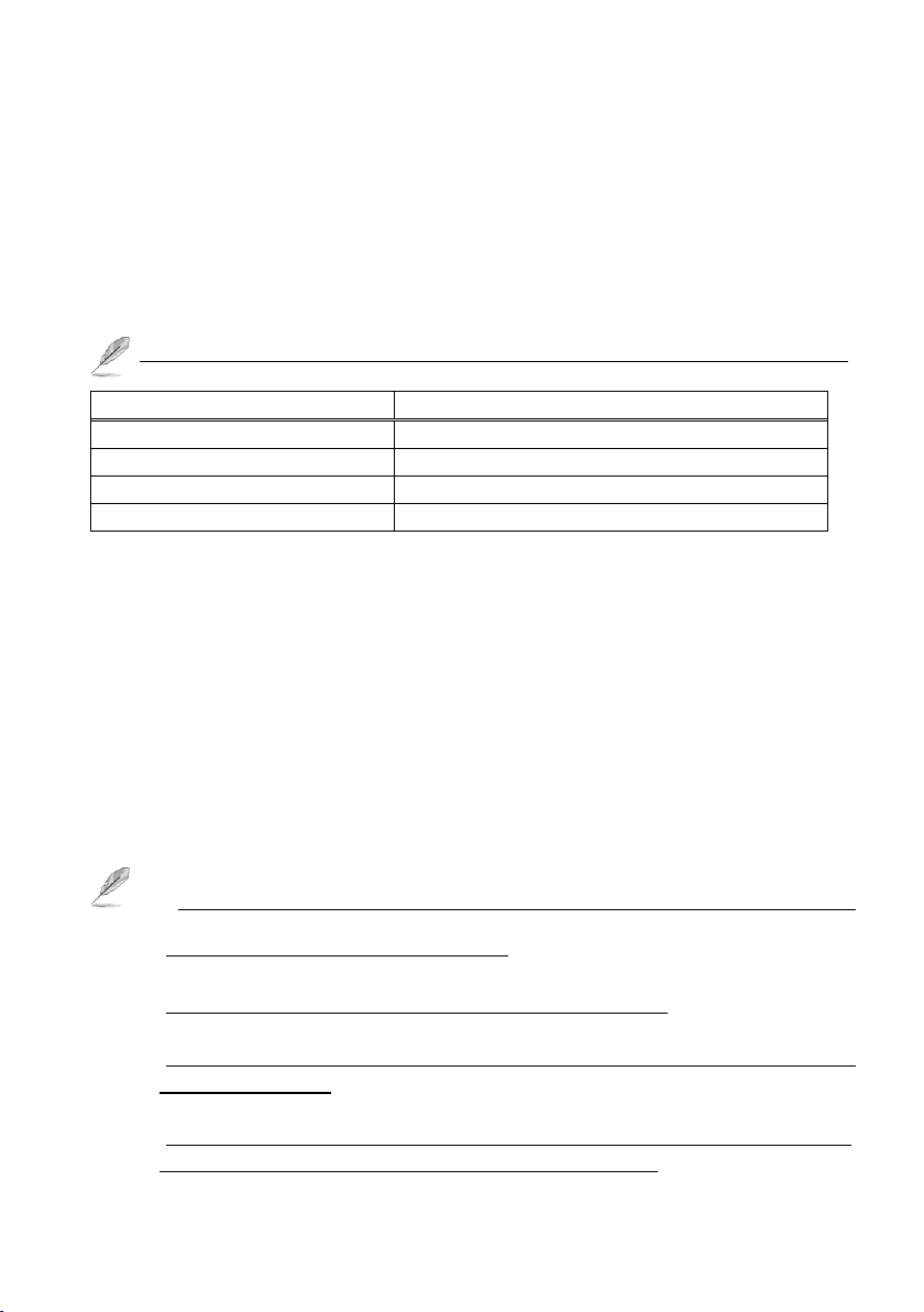
Witness AS Pro
CP-1400AS XP
Witness 1416/3416ASE Pro
CP-1416ASE XP/ CP-3416ASE XP
Witness 1404/3404HS Pro
CP-1404HS-T XP/ CP-3404HS XP
Witness 1160/1320RD Pro
CP-1160RD/ CP-1320RD Deluxe
Microphone: 2Vp-p output is required for audio recording.
Modem speed 33.6K or better; external modem that supports Wave files
is recommended.
CP Series DVR Board: Please be sure that the CP series DVR board has
been installed in the PC. For the CP series DVR board system
requirements and installation, please refer to the table in Appendix B
and the CP series DVR board installation guide.
There are several models for different software. It is described as below:
2-1-2. EZNetwork and EZModem
Desktop or Notebook PC with Pentium III 500 MHz CPU or better.
Operating system: Windows 98 Second Edition, ME, 2000 or XP.
256 MB free hard drive space minimum.
Sound card and speakers are required for sound alarm/effects.
24-bit (true-color) VGA card or better.
Modem speed 33.6K or better.
1. EZNetwork is used by TCP/IP and the EZModem is used by
modem-to-modem remote viewing.
2. The output level of microphone must be over V2p-p.
3. The modem must support Wave files; otherwise can not work when you
use “Phone call”.
4. The file size of compression image depends on resolution, compression
method, compression rate and testing environment.
Page 18
18
2-2. Installation Prerequisites
Make sure you install the EZWatch Pro software before you install the capture
card(s) in the PC.
2-3. Installing EZWatch Pro 3.1 HD Software
Depending on the video capture card you are using, follow the steps below to
install EZWatch Pro 3.1HD onto your computer. Precede to the step below that
matches the Capture Cards model number. The model number is displayed on a
white sticker on the back of the capture card.
GO TO STEP #1 for Capture Card CP-1400-AS
GO TO STEP #2 for Capture Card CP-3404HS
GO TO STEP #3 for Capture Card CP-1416ASE or CP-3416ASE
Note: It is necessary to install the EZWatch Pro 3.1 software first and then install
the video capture cards. If the computer has anti-virus software running it must
be turned off before you install. After installation, it can be reactivated.
Step 1: (For board #CP-1400AS)
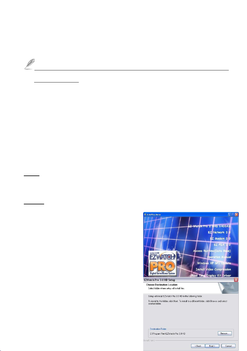
1a. Insert the EZWatch Pro 3.1HD CD into
your CD-ROM drive, the EZWatch Pro
3.1HD installer will appear automatically
within 30 seconds listing all the available
software. Select "EZ Watch Pro 3.1 HD
1400AS". If the EZWatch Pro 3.1HD
installer does not appear on the screen
automatically, click "Start", then "Run" and
execute “d:\setup .e xe” o r w h a tever d rive
letter pertains to your CD-ROM drive.
1b. Click n e xt o n the “W elcom e to the
InstallShield Wizard for EZWatch Pro 3.1
Page 19
19
H D ” spla sh screen . N ext you will see the screen to the right. Click next to install
EZWatch Pro 3.1HD to the default location (recommended). If you want to install
the software into another directory, click browse and choose the path to where
you would like setup to install EZWatch Pro 3.1HD. After you click next, Setup will
install EZWatch Pro 3.1HD into the directory in you specified. You will then see a
popup window that lists all the installed applications. Close this window and
continue with the installation.
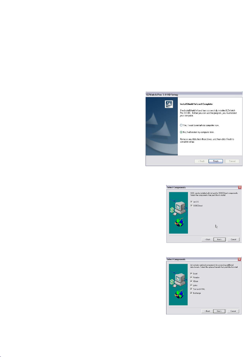
1c. To finish you will see the
“InstallShield Wizard Complete” splash
screen. You will see this screen if EZWatch
Pro 3.1 HD was installed successfully.
Setup will now ask if you want to restart
now or later. C h o o se th e second op tio n , “N o,
I will restart my computer later” a n d click
the finish button at the bottom. EZWatch
Pro 3.1 HD is now installed. Now, continue
to the next application that needs to be
installed off the installation disk in order to
successfully run EZWatch Pro 3.1 HD.
1d. Install Access Runtime:
Now from the “A u toPlay M e n u ”, click o n “Access
Runtime(Database)” Yo u w ill no w see the Data
Access Objects (DAO) Splash Screen, on the
welcome screen click next to continue. On the
Select Components screen, you should see Jet 3.5,
and ODBCDirect checked, leave both checked and
click next.
1e. Here you will see the additional components
needed for the install of Jet 3.5. There should be six
of them, and they all should be checked. Excel,
Paradox, XBase, Lotus, Text and HTML, and
Exchange. Leave all six components checked and
click next to start copying the files to your computer.
When finished installing, you should see an
In fo rm atio n b a r te llin g you th at “D ata A ccess
Page 20
20
Objects (D A O ) su ccessfully in stalle d ”. C lick O K to fin ish th e in sta llatio n.
Step 2: (For board #CP-3404HS)
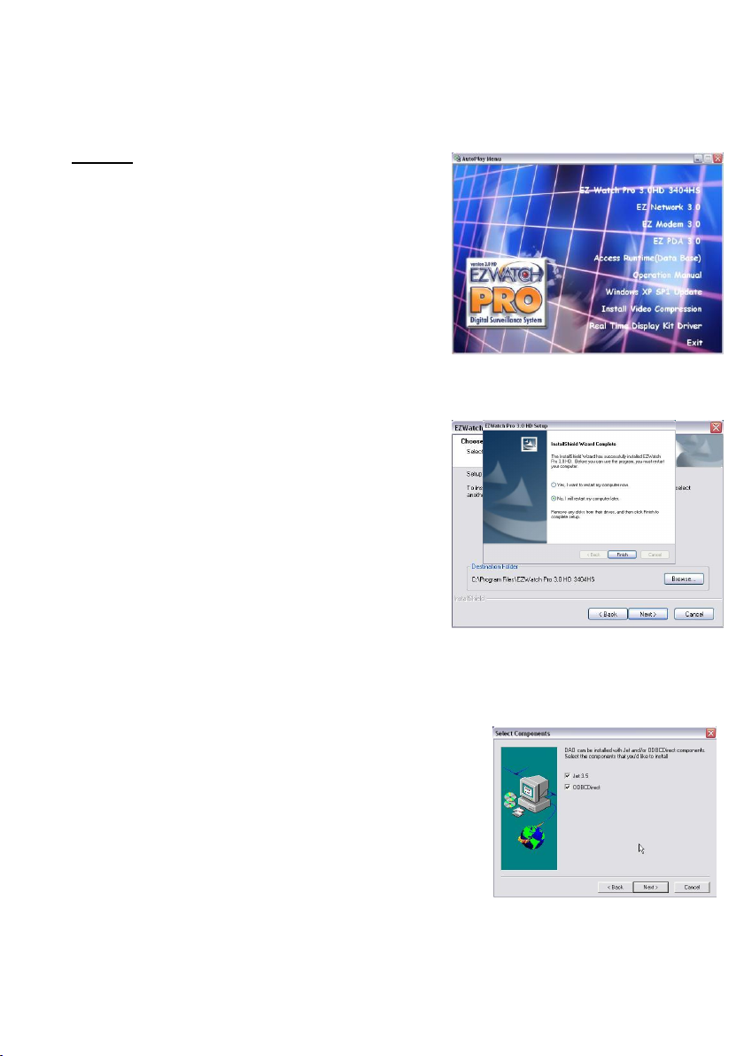
2a. Insert the EZWatch Pro 3.1 CD into your
CD-ROM drive, the EZ Watch Pro 3.1HD
installer will appear automatically within 30
seconds listing all the available software.
Select "EZ Watch Pro 3.1HD 3404HS". If
the EZWatch Pro 3.1HD installer does not
appear on the screen automatically, click
"Start", then "Run" and execute
“d:\setup.exe” o r w h a tever d rive le tter
pertains to your CD-ROM drive.
2b. Now, the installer should have launched
for you, click next to begin setup. You should
see the following screen asking you where you
would like to install EZWatch Pro 3.1HD. Click
next if you would like to install the software in
the current location. If you would like to
install into another directory, click browse and
select the location that you would like to
install the EZWatch Pro 3.1HD software. You
will see the installer copying the EZWatch Pro
3.1HD files to the location you selected. When finished copying files, setup will ask
if you want to restart your computer now or restart later. C lick “N o I w ill restart my
com pu ter later” an d click fin ish ed .
2c. Install Access Runtime:
N ow from th e “Auto Play M enu ”, click o n “Access
Runtime(Database)” Yo u w ill no w see th e D ata
Access Objects (DAO) Splash Screen, on the
welcome screen click next to continue. On the
Select Components screen, you should see Jet 3.5,
and ODBCDirect checked, leave both checked and
click next.
Page 21
21
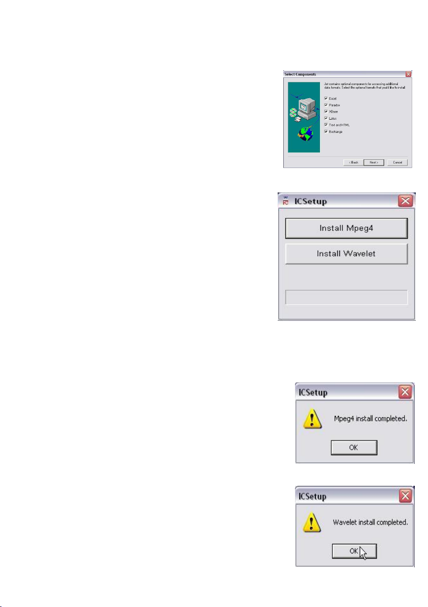
2d. Here you will see the additional components
needed for the install of Jet 3.5. There should be six
of them, and they all should be checked. Excel,
Paradox, XBase, Lotus, Text and HTML, and
Exchange. Leave all six components checked and
click next to start copying the files to your computer.
When finished installing, click OK to finish the
installation.
2e. Back to the “A u toPlay M e n u”, click on the
“Install V id eo C om pressio n ” lin k to start the in sta ll
of the two supported video compression types.
They are MPEG4 and Wavelet.
Note: Upon starting the install of either Mpeg4, or
W avele t, if you see a scre e n sa yin g “M p eg4 or
W avele t, a lready in stalled , con tin ue o r not?” Select
“N o ” an d can cel th e in stalla tio n. W indo w ’s X P
already has a built in Mpeg4 and Wavelet codec,
therefore you do not need to install the one we
prov id e. If yo u d o n ’t se e th is m essage, contin ue b elow with the install.
2f. First, click “In stall M P E G 4 ” to start the in sta llatio n .
MPEG4 is now installed. You may get a splash screen
saying, “M peg4 alrea d y in sta lled , co n tinu e or not?”
Select yes and continue with the install.
2g. Now click on the “In sta ll W avelet” lin k to start
the installation. Wavelet in now installed. You may get
a spla sh scree n saying “W avelet is alrea d y in stalled ,
contin ue o r not?” S elect yes a n d co n tinu e w ith the
Page 22
22
install.
EZWatch Pro 3.1 HD is now installed. Now you can turn the computer off, unplug
the power cord from the back of the machine, and continue to the Video Board
Installation section.
Step 3: (board #CP-1416ASE or P-3416ASE)
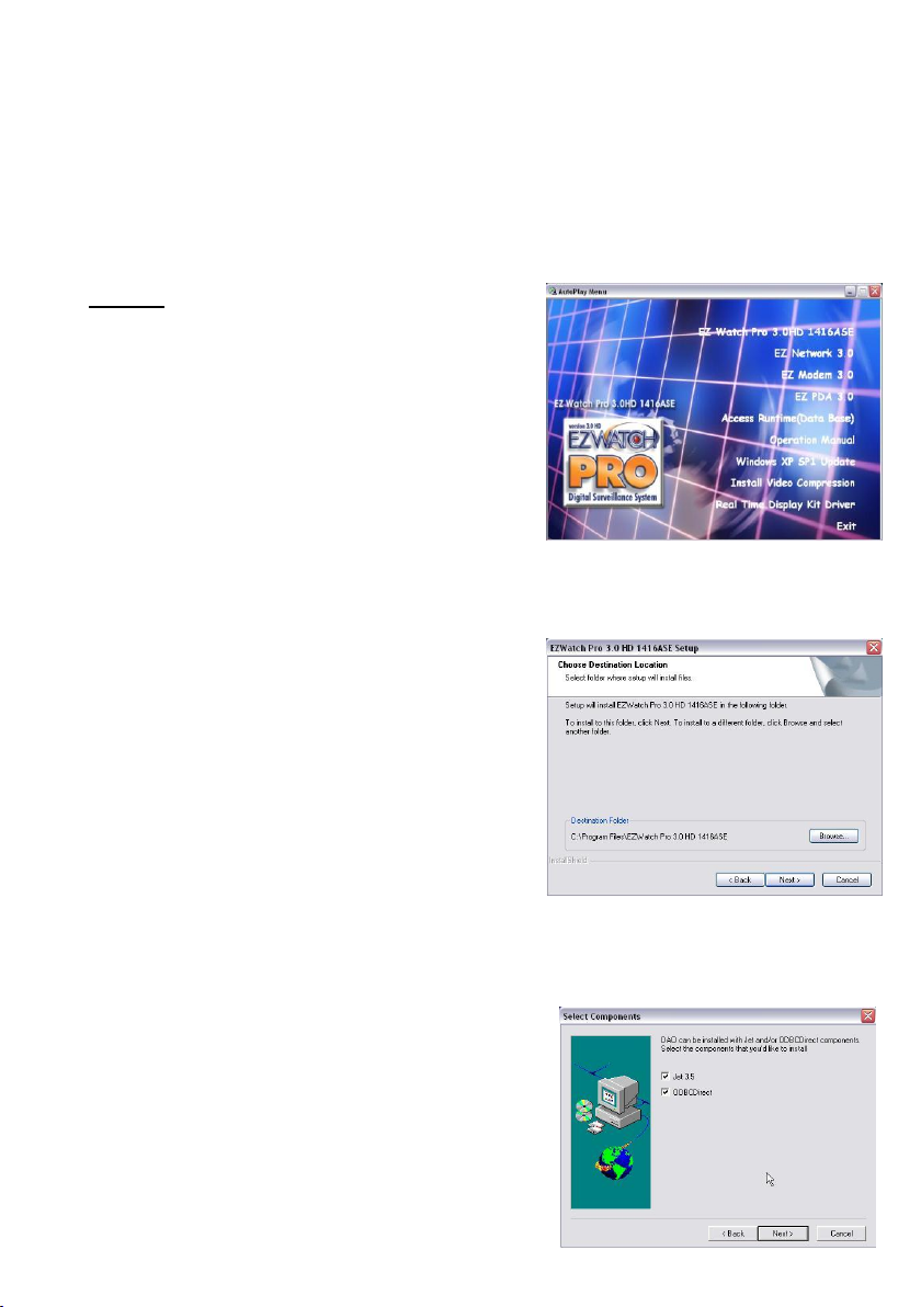
3a. Insert the EZWatch Pro 3.1HD CD into
your CD-ROM drive, the EZWatch Pro 3.1HD
installer will appear automatically within 30
seconds listing all the available software.
Select "EZ Watch Pro 3.1HD 1416ASE /
3416ASE". If the EZWatch Pro 3.1 installer
does not appear on the screen automatically,
click "Start", then "Run" and execute
“d:\setup.exe” o r w h a tever d rive le tter
pertains to your CD-ROM drive.
3b. Now, the installer should have launched
for you, so click next to begin setup. You
should see the following screen asking you
where you would like to install EZWatch Pro
3.1HD. Click next if you would like to install in
the current location. In case you would like to
install into another location, click browse and
select the location that you would like to
install EZWatch Pro 3.1HD. You will see the
installer copying the EZWatch Pro 3.1HD files
to the location you selected. When finished
copying files, setup will ask if you want to restart your computer now or restart
la ter. C lick “N o I w ill re start m y com puter later” a n d click finished .
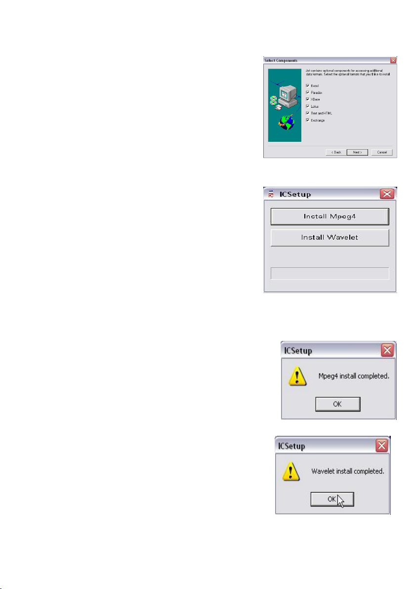
3c. Back to the AutoPlay Menu, click the one
la b e le d “Access Runtime(Database)” Yo u
will now see the Data Access Objects (DAO)
Splash Screen, and on the welcome screen
click next to continue. On the Select
Components splash screen, you should see
Page 23
23
Jet 3.5, and ODBCDirect checked, leave both checked and click next.
3d. Here you will see the additional components
needed for the install of Jet 3.5. There should be
six of them, and they all should be checked.
Excel, Paradox, XBase, Lotus, Text and HTML,
and Exchange. Leave all six components
checked and click next to start copying the files
to your computer. When finished installing, you
should see an Information bar telling you that
“D ata A ccess O bjects (DAO) successfully
insta lled ”. C lick o k to fin ish the in stalla tio n .
3e. Back to the AutoPlay Menu, click on the
“Install V id eo C om pressio n ” lin k to start the
install of the two supported video compression
types. They are MPEG4 and Wavelet.
Note: Upon starting the install of either Mpeg4,
or W avelet, if yo u see a scree n sayin g “M p eg 4 or
Wavelet, already insta lled , co n tinue or not?”
Select No and cancel the installation. Windows XP already
has a built in Mpeg4 and Wavelet codec, therefore you do not need to install the
one w e p ro vide. If you d o n’t see this message, continue below with the install.
First, click “In stall M PEG 4” to sta rt the installatio n .
MPEG4 is now installed.
N ow , click on the “Install W avelet” lin k to sta rt
the installation. Wavelet in now installed.
EZWatch Pro 3.1HD is now installed. Now you can
turn the computer off, unplug the power cord from
Page 24
24
the back of the machine, and continue to Section 2 – Video Board Installation.
2-4. Video Board and Driver Installation
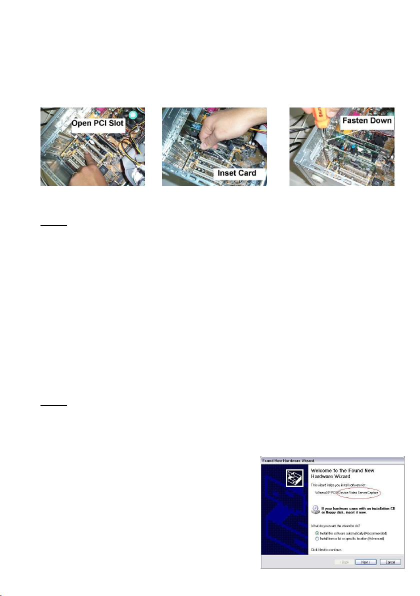
This procedure is for installing the capture card and software driver into the PC.
Step 1: Find an open PCI slot Step 2: Insert PCI card Step 3: Fasten Card Down
Note: One PCI slot is needed per Video Capture Card. Also make sure that the
power cord is removed from the back of your computer before installing the video
capture cards
Once the software has been properly installed, you can now shut down your
computer and remove any side panels so that you can insert the video capture
boards. Follow Steps #1, #2, and #3 shown above to properly insert the video
capture cards. Once cards are properly inserted in the computer, you can put the
side panels back on and plug back in the power cord. Turn on your computer.
O nce you r com pu ter sta rts b a ck u p , the “Foun d N e w H ard w a re W izard” w ill
appear on the screen prompting you to install the drivers for the video capture
boards. Follow the steps below to install the video capture board drivers. This
step must be correctly completed for the system to operate!
Note: If yo u r com pu ter is run n in g the curren t service p ack in W in do w ’s X P
(Service Pack 2) th e n the “Fou nd N e w H ardw are W izard ” w ill first ask yo u if it can
connect to the Internet to search for a suitable driver. Choose the third option >
No, I do not want to search, and continue with the steps below.
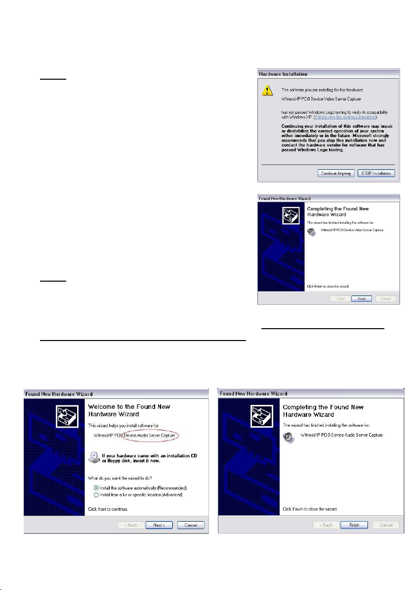
Step#1: The found new hardware wizard should
now be displayed on your screen as shown to the
rig ht. S im ply ch o o se the default o p tion “Insta ll
th e softw are a u tom atically (Reco m m ended)”a n d
click next at the bottom.
Page 25
25
Note: You may also get a warning screen like the
one below fro m W in do w ’s telling you that the
driver’s yo u a re insta llin g have not passed
W ind o w ’s Logo Testin g . C h oose “Con tinue
A ny w ay” to con tinue w ith the driver in stall.
Step#2: Once the wizard has completed
copying files to your computer, you will see
“Com pletin g the Found N e w H ardw are W izard ”
screen. Simply choose Finish at the bottom and
the wizard will have successfully installed the
first device driver for you.
Note: Each video capture card that you install in
your computer will prompt you to install two
drivers, one for the video and one for the audio.
The step just performed installed the driver for the video. You will also install a
video driver for each card as show in step #3 below. So you will need to repeat
the process twice for each card you install.
Step#3: Now install the second driver for the video capture card the exact same
way as before. This time you will notice that it is installing the audio driver.
Page 26

26
The install should go fairly fast for the audio driver. So once it is installed, click
finish to complete the setup. Once again, if you have installed more than one card,
you will need to repeat the above process for each card. After you have installed
each driver for all the boards you have installed in the computer, you can restart
your computer.
EZWatch Pro 3.1 HD is now installed. You may now proceed to the next page to
setup a few Windows settings before running the EZWatch software.
2-5. Setup Windows XP to run EZWatch Pro 3.1 HD
EZWatch Pro 3.1 HD requires specific settings in Windows XP to assure a reliable
and constant operation. Please make sure that you setup your Windows XP
computer with the following settings:
A. Power Management: You can ch a n g e the w ay W in d ow ’s hand les the Pow er
Management by doing the following steps:
Step #1: click “S tart”, “Co n trol Pa n e l” then click “Perfo rm an ce and
Main tenance” th en click “Pow e r O ptio n s”.
Step #2: U nder Pow er S chem es, C hoose “A lw ays O n”. U n de r S ettin g s fo r
A lw ays O n p o w e r schem e, Turn off M o n itor sh o uld b e “N ever”, Turn off H ard
D isks shou ld b e “N eve r”, a n d S ystem S ta n d by sh o uld b e “N ever”.
Step #3: Please sele ct the “O k” b utto n at the b ottom to save the setting s.
B. Recycle Bin: You n e ed to ch an g e the w a y W in d ow ’s d elete s files o ff o f you r
hard drive. Follow the steps below to configure your recycle bin.
Step #1: O n you r D eskto p , righ t click “Recycle B in ” then ch oo se
“Prop e rtie s”.
Step #2: O n the G lob al Tab , m ake sure “U se o n e settin g fo r all drives” is
clicked. N e xt, ch e ck the b o x labeled “D o not m ove file s to the R ecycle B in .
Remove files im m ed ia tely w hen d elete d ”. La stly, m ake su re th e b o x labeled
“D isp la y delete con firm atio n d ia lo g ” is UN-Checked.
Step #3: Please select th e “O k” b u tto n at the bottom to save th e settings.
Page 27

27
C. Display Properties: You need to make sure the correct settings are enabled
before you run EZWatch Pro 3.1 HD. Your computer may or may not already have
these settings in place. Follow the steps below to ensure the correct display
settings are enabled on your computer.
Step #1: C lick “Start”, g o to “C on tro l Panel”. In the Control Panel, choose
“A pp earan ce and T h em es”, a n d then choose “D isp lay ”. T h is w ill p o p u p the
“D isp la y Prop erties” w ind o w .
Step #2a: Click o n the “Settin g s” tab , tow ards the b ottom you w ill see
“Scre e n R esolu tion”. Th is n e ed s to b e o n eith er 80 0 x6 0 0 or 1024x768 for
optim al resolutio n . Yo u sh o u ld also see “C o lo r Q uality”, th is n eed s to b e o n
the highest setting that your VGA card will allow. EZWatch Pro 3.1 HD will
only run in 2 4 bit color q u ality or high e r. S o, if your V G A card w on ’t su p po rt
at least 24bit color quality, then you will need to use another VGA card that
will support at least 24bit color quality.
Step #2b: Screen Saver. C lick on the “S creen S aver” ta b , a n d tow ards
the bottom you will see the Screen Saver Section. Here you will need to
use th e d rop d o w n m en u a n d ch oo se “N on e” so that there is n o screen
saver that will automatically come on after a period of inactivity.
Step #3: Please select “A pply” a t the bottom ... you will see your screen go
black for a short period. C lick “O k” to save all your settings.
For any technical information or if you need technical assistance, please call our
toll free technical support line at 866-241-3400 extension 106 or you can email us
at [email protected]
Our sales and technical support department is open Mon-Fri, 6:00a.m.To 6:00
p.m. Mountain Standard Time. We thank you for purchase, and will continue to do
our very best to assist you in any future needs that may arise.
Windows XP is now ready to run EZWatch Pro 3.1 HD.
Installation is Complete
Page 28
28
2-6. Software Installation Procedures
This procedure for installing the Witness Software is the same for all supported
windows environments. Please follow the instructions below to install the
EZWatch Pro, EZNetwork and EZModem Software.
2-6-1. EZNetwork Installation Procedures (TCP/IP)
This chapter walks you through the installation and setup process for Remote
client software, EZNetwork. Please follow the steps below to complete the
installation.
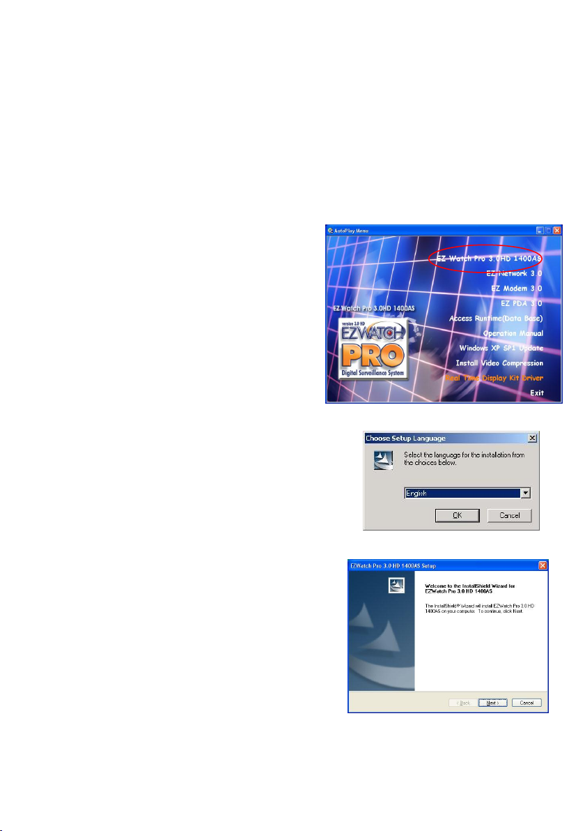
Step1. Please select the ―EZNetwork
S o ftw a re‖ option for the
software installation menu as
showing in Fig. 2-4-2.1 below to
install.
Fig. 2-4-2.1: Installation Menu
Step2. Select an installation language and click
the ―O K ‖ button to continue.
Fig. 2-4-2.2: Choose a setup language
Click the ―N e x t‖ button to continue.
Fig. 2-4-2.3: Installation start-up
Page 29
29
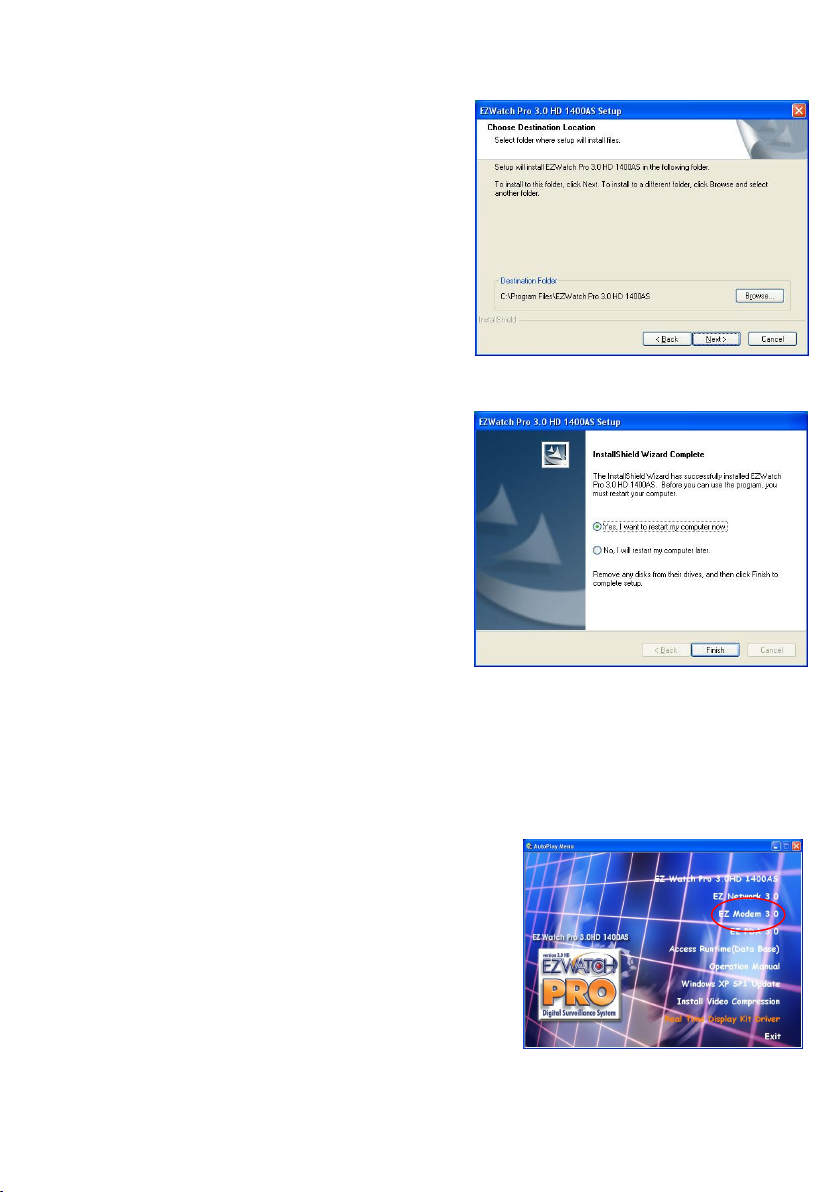
Step3. Click the ―B row ser‖ button to
change the installation directory, or
click the ―N ext‖ button to continue
(recommended).
Fig. 2-4-2.4: Select installation directory
Step4. Click the ―F in ish‖ button to
complete the install and restart your
computer.
Fig. 2-4-2.5: Finish the install and restart
2-6-2. EZModem Installation Procedures
This chapter walks you through the installation and setup process for Remote
client software, EZModem, for modem-to-modem connections. Please follow the
steps below to complete the installation.
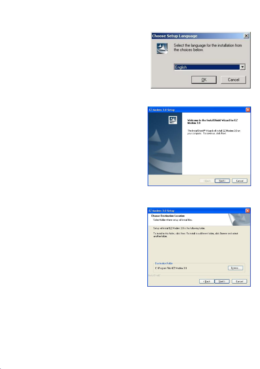
Step1. Please select the ―EZNetwork
S o ftw a re‖ option for the software
installation menu as showing in Fig.
2-4-3.1 below to install.
Page 30
30
Step2. Select an installation language and
click the ―O K ‖ button to continue.
Step3. Click the ―N ex t‖ button to
continue.
Step4. Click the ―B ro w ser‖ button to
change the installation directory, or
directly click the ―N e x t‖ button to
continue (recommended).
Fig. 2-4-3.2: Choose a setup language
Fig. 2-4-3.3 Installation start-up
Fig. 2-4-3.4: Select a installation directory
Page 31
31
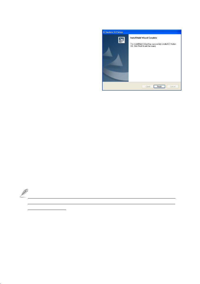
Step5. Click the ―F in ish‖ button to
complete.
F
Fig. 2-4-3.5: Finish the installation
2-6-3. PDAView Pro Installation Procedures
To install the PDAView Pro program into a PDA or Smart Phone, please follow the
installation steps below:
Plug your PDA or Smart Phone via USB or Com port to a PC installed
with Microsoft ActiveSync.
Run Microsoft ActiveSync in the connected PC and make sure both
the PDA and PC are synchronized.
Insert our CD into the CD-ROM drive of the PC and run the
Install.exe in the CD-ROM root directory.
In the setup dialog box select PDAView Pro and click Next.
Click Brows if you wish to specify another destination directory;
otherwise click Next and follow the rest of the instruction to
complete the installation.
The PDA must use the Pocket 2002 or 2003 and the Smart phone with
Windows Mobile 5.0 or above Operation System when you running the
PDAView program.
Page 32
32
Chapter 3 System Configuration
3-1. EZWatch Pro Functions Overview
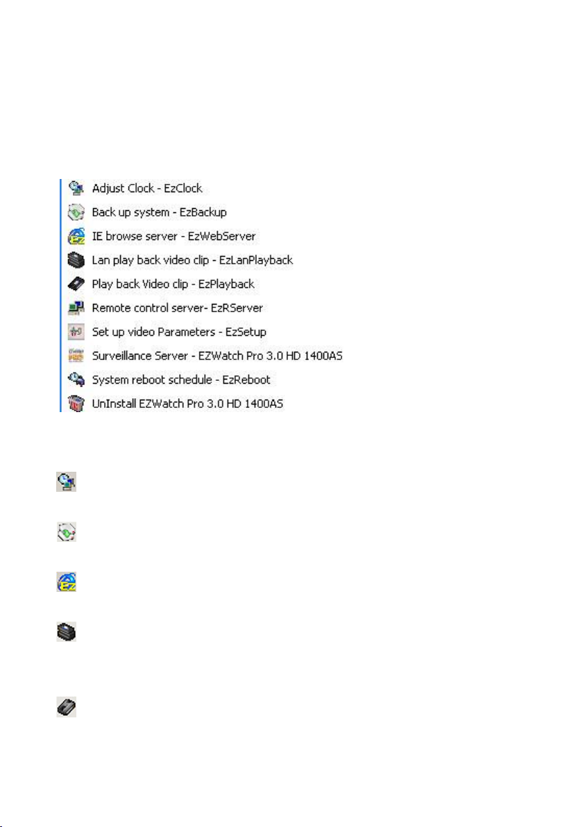
Since EZWatch Pro has been installed on Windows, you can find several icons in
the Windows ―Start‖ menu as showing in Fig 3-1-1.1 below.
Fig. 3-1-1.1 Windows Start Programs EZWatch Pro
Function Descriptions:
Adjust Clock-EzClock: To synchronize the time clock of DVRs with
Standard Time Server.
Back up system-EzBackup: To back up the video clips in another storage
device.
IE browse server-EzWebServer: To view the Local DVR Server via IE
browser.
LAN play back video clip-EzLanPlayback: Provides remote client to
playback video clips of EZWatch Pro DVR via LAN, such as playing back video
clips at the EZWatch Pro DVR.
Play back video clip-EzPlayback: To playback video clips of EZWatch Pro
Page 33
33
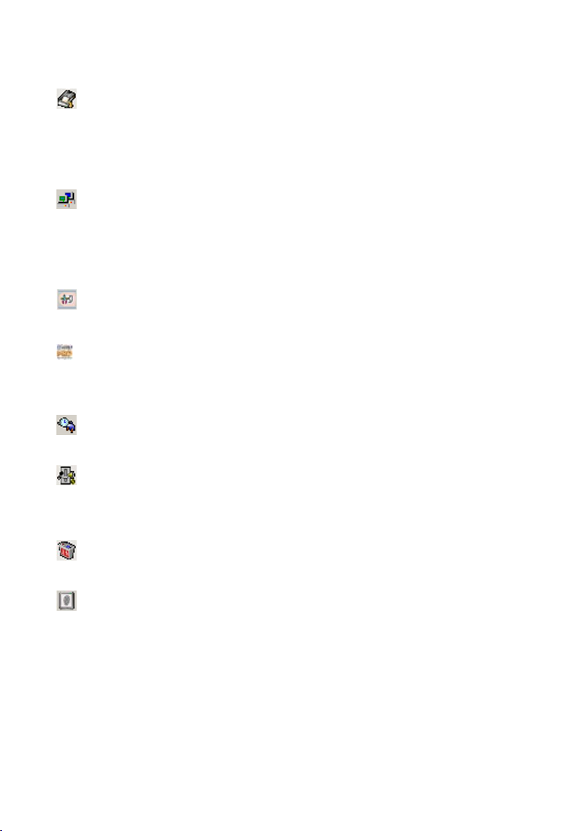
DVR from any Windows base PC.
POS Playback-EzPosPlayback: Access the “Text record” u nder V iew Log to
search for all the transaction lists within specific time frames. Click on the
re le vant transaction list of “Text reco rd” an d the video will playback the
selected time record of this transaction text in conjunction with the video clip.
Remote control server-EzRServer: Allows remote client to control the
EZWatch Pro DVR via EzRClient program through Internet. The Remote
client can set up the EZWatch Pro DVR from remote site such as operating at
the local.
Set up video Parameters - EZSetup: Allows you set up system
configuration for EZWatch Pro.
Surveillance Server-EZWatch: Main program, provide user live viewing,
video recordin g, m otio n d ictio n . … e tc. fu nction s, a n d also be a video se rver to
transfer the video stream to a remote user via PSTN, ISDN, LAN or Internet.
System reboot schedule-EzReboot: Provides user to set up system
reboot schedule to keep system surveillanc routine.
Two ways communication-EzTalk: Real-time audios from designated
locations are simultaneously transmitted to both the control center and
designated DVR sites.
Uninstall EZWatch Pro series Pro: This will remove EZWatch Pro program
from the computer. It will not remove the device driver.
Access Control-EzFingerKey: To integrate with the EZWatch Pro, provide
supervisor entry access control and management easily. Please refer to
FAC-500 FingerKey user manual for detail.
3-2. How to Prevent System Crashes
This chapter introduces several settings to prevent a Windows system crash when
running the EZWatch Pro system. Please follow the instruction below to set up
Page 34
34
Windows running with EZWatch Pro in optimum performance status.
3-2-1. Power Management Setup
Please follow the steps below to set up Windows Power Management.
Step1. C lick W ind o w s “Start” m en u “Settings” “Control Panel” and
th e n select the “Power Management” icon .
Step2. S elect th e “Power Schemes” tab .
Step3. Change the Power Schemes to ―A lw a ys o n ‖; select ―N ever‖ to turn
off hard disk and ―N e ver‖ to turn off monitor.
Step4. Click ―O k‖ to complete the setup.
3-2-2. Windows File System Setup
Please follow the steps below to set up Windows File System.
Step1. Click Windows ―Start‖ menu ―Settin g s‖ ―C on trol P an e l‖ and
then select ―System ‖ icon.
Step2. Select the ―A d v a n tag e ‖ tab, an d press th e “S e tting ” b u tto n in
―P e rfo rm an ce ‖ section, then click ―O p tim u m P erfo rm an ce‖.
Step3. Click ―O k‖ to complete the setup.
3-2-3. How to setup System Reboot Schedule
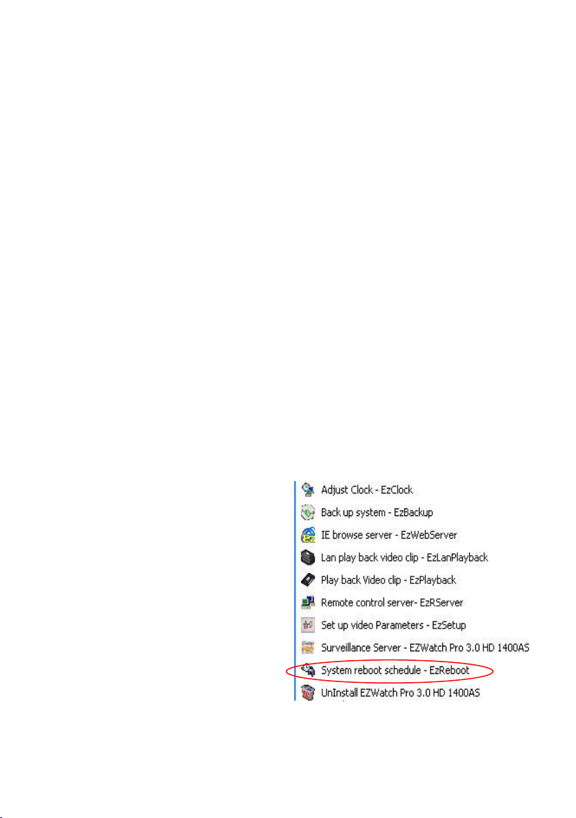
It is recommended that you use the System Reboot Schedule (EzReboot) to keep
your operating system running fresh. Please follow the instruction below to
complete this configuration.
Step1. Click Windows ―Sta rt‖
menu ―P rog ra m s‖
―EZWatch Pro‖ and then
select ―Syste m re boot
schedule – EzR eb oot‖.
F
i
g. 3-2.3.1 System reboot schedule
Page 35
35
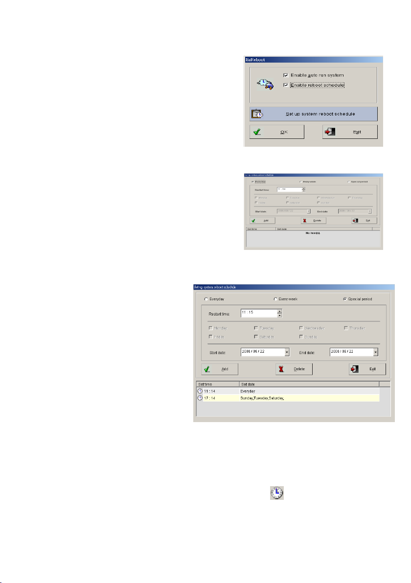
Step2. Ch e ck “Enable au to run system ” and
“En a b le reboot sch ed u le ”.
a.) Enable auto run system: To auto run
the System reboot schedule –
EzReboot function when Windows
starts.
b.) Enable reboot schedule: To reboot
system by setting schedule.
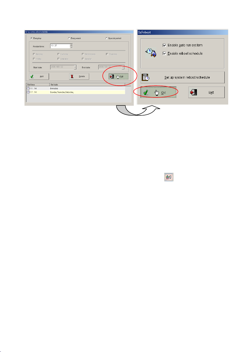
Fig.3-2-3.2
Step3. Click the ―S e t up system reb oo t
sche d ule‖ button to set up the
system reboot schedule.
Step4. Select reboot schedule type by
choosing Everyday, Every week and
Special period.
Fig.3-2-3.3: Set up schedule time
Step5. Setup a reboot
schedule of your
choosing and press the
―A dd ‖ button.
Fig.3-2-3.4: Add the reboot schedule
Step6. You can set up multiple reboot schedules for the EZWatch Pro system.
When you are finished adding the schedule setting, press ―E x it‖ button
to exit the setting interface, then press ―O K ‖ button to start the system
reboot schedule function. There will be a icon in the Windows
system tray at the bottom right.
Page 36
36
3-3. EZWatch Pro System Configuration
This chapter introduces the EZWatch Pro system configuration to make system
perform in optimum condition. Please follow the instruction below to complete
each setting.
3-3-1. Set up video Parameters-EzSetup
To ch an g e the d efau lt para m eter settin gs, p lease go to the path : W ind o w s “S tart”
“Program s” ―EZWatch Pro‖, and click the icon to display the
parameter setup interface. According to the different models of the EZWatch Pro
DVR board, the “Set u p video param eters” interface m ay b e chan g e d . Please b a se
on your EZWatch Pro DVR board model to refer to the instruction below for
setting.
Page 37
37
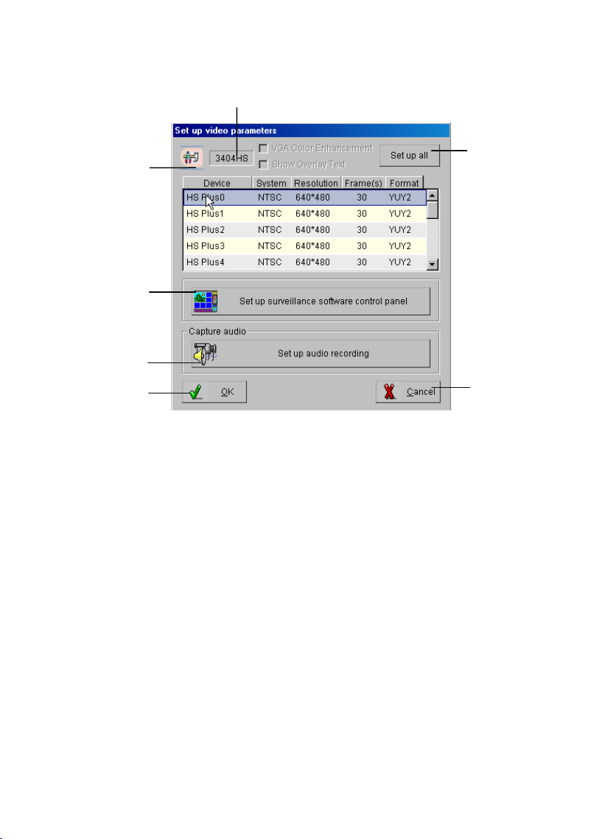
Fu nctio n de scrip tion o f the ―S et u p v id eo param e ters‖ in terface:
2
3
4
5
6
7
Fig. 3-3-3.1 Setup Video Parameter - EzSetup
1. Model Name Display: Display the DVR board model name.
2. Cameras Display Window: List cam era s for settin g “fram e rate” and
“device en ab le /disab le ”, user can sim ply dou b le click th e m o u se left
button o n selected cam era to ch an g e th e settin g. The n u m ber “0”
camera can set up all video system type (e.g. NTSC/PAL) and video
resolution. [see Camera Display Window Info below]
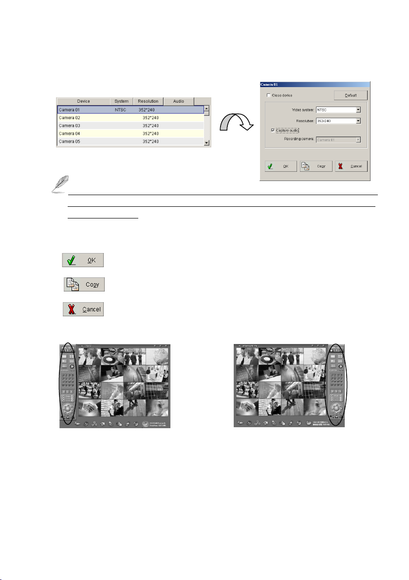
3. Set up surveillance software control panel: To set the video
control panel of the main program or playback program on the right
sid e or le ft sid e in the “surveillan ce server”.
4. Set up audio recording: A ccordin g to the D V R b o a rd m od e l, the “Set
up audio recording ” fu n ction m ay be differe n t. This fu n ctio n is to
enable/disable e a ch ch an n el’s a u d io recordin g (For C P -1400AS /
CP-3404HS / CP-3408ASE / CP-3416ASE only).
5. ―O K ‖ bu tto n : To co n firm th e setting an d e xit “S et up vid eo
para m eters” in terfa ce.
6. ―C an cel‖ bu tto n : To exit the “S et up video para m eters” in terface
without saving changing.
7. ―Set u p all‖ b u tto n: To set u p all cam era s’ video system type,
Page 38

38
resolution and frame rate.
Double left click on selected camera
Camera Display Window Info
For CP-1400AS/CP-3408ASE/CP-3416ASE DVR board model first
camera setup interface:
For CP-1160RD/CP-1320RD DVR board model first camera setup
interface:
For CP-3404HS DVR board model first camera setup interface:
Page 39
39
Double left click on selected camera
Left side video control panel
Right side video control panel
For CP-1160RD/ CP-1320RD DVR board model first camera setup
interface:
Ple a se enab le “Close camera “ if the camera device is not connected to
the DVR board. It will increase the display/recording speed and reduce
the system load.
Button Description:
: To confirm the setting and exit.
: To duplicate another camera setting to current camera.
: To exit without saving.
Page 40
40
Chapter 4 EZWatch Pro System Operation
This chapter describes the operation of the EZWatch Pro program
4-1. Surveillance Server Program
Surveillance Server-EZWatch Pro is the primary program of the Witness
surveillance system, it provides user total CCTV security solutions which
include live viewing, video recording, motion diction, multiple ways emergency
notification to user, E-map for easy entire site management, events list,
schedule recording, remote client surveillance connection support via
WAN/LAN/Internet/Intranet multiple connections types and video clips
playb ack fun ctio n s… e tc. P lease fo llo w the instructio n b e lo w for m ore d etail.
Start Surveillance Server-EZWatch Pro Program: Please click the
Windows ―Sta rt‖ m e n u ―P rog ra m s‖ EZWatch Pro, and click the
Surveillance Server-EZWatch Pro to start the program.
Page 41
41
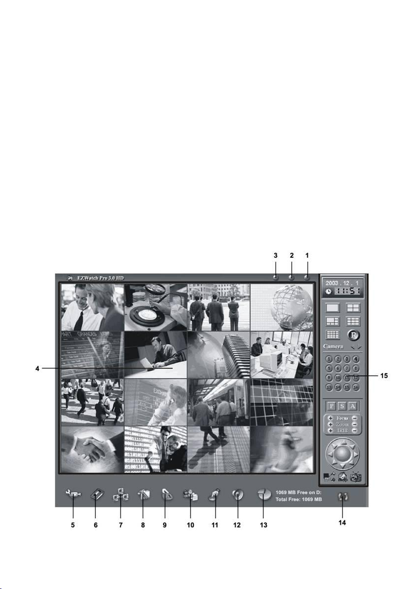
Surveillance Server Functions Description:
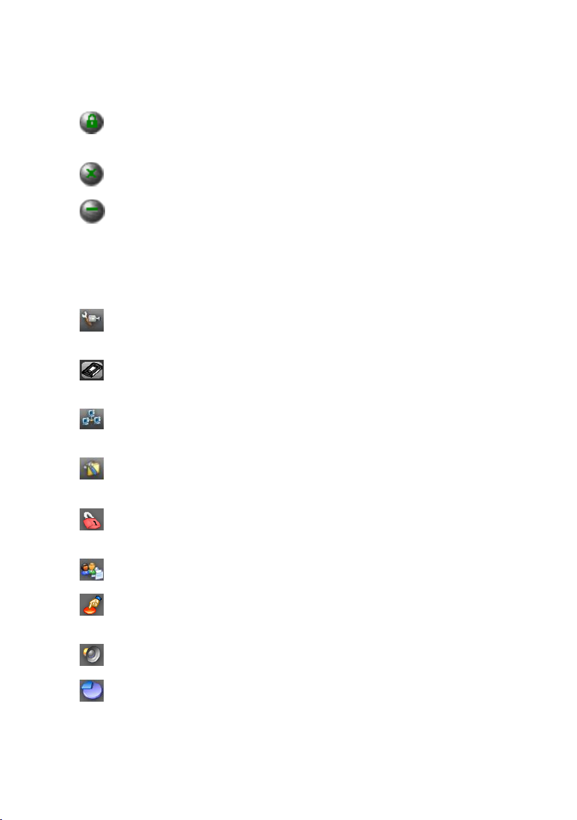
1. Login/Logout button: If it is the first time to start this program,
user needs to login the name and password to access this program.
2. Exit button: To exit this program.
3. Minimize button: To minimize this program.
4. Display Screen: To d isp lay chan n els’ vid eo. D ouble click o n a vid eo
channel to enlarge the video image, and click again to back to original
display mode. Click right of Mouse on a video channel to change the
video color parameter or hidden camera.
5. Camera configuration: To set up the DVR settings (e.g. recording
function, alarm system, motion detection etc.) for cameras.
6. Playback video clips/POS Playback: To o p en th e “Playb ack vid eo
clip s” o r “EzP O S P layback” fu nctio n .
7. Network configuration: To set up DVR system network
configuration.
8. System configuration/EzTools: To select the “S ystem
configu ration ” o r “EzTools” fun ctio n.
9. Set up privileges: To manage the account of the DVR access
authority.
10. View log: To view, save and clean the different kind of system logs.
11. Set up I/O port: To set up DVR peripheral device for system
integration.
12. Stop sound alarm: To stop the alarm when it is sounding.
13. Storage device configuration: To set up DVR image storage
configuration.
Page 42
42
14. Toggle switch: To provide user to select Real time display and
Recording mode.
15. Video control panel: Provide DVR display control, recording, PTZ
camera controlling, TV out and eMap functions.
16. ―ES C ‖ H id e too l b ar: Pressin g “ESC” key o n key b o a rd w ill h id e the
tool bar of main screen until ―ES C‖ is pressed again.
How to change the video parameters?
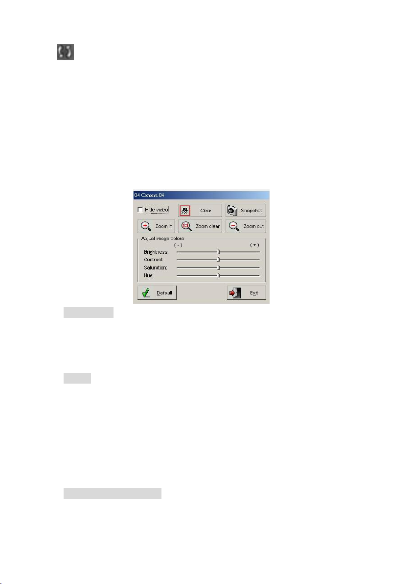
Video Tools: Right click your mouse on the video screen so that you
can modify the parameters of the image.
Hide video m ake s th e given cam era’s im ag e s on yo ur m on itor disapp ear;
however all of its other functions keep working. For example, if you
select this, the chosen cam era ’s w in d o w section in EZWatch Pro will turn
blank, but the camera itself can still continue to record.
Clear will clear the red border. Upon detection, the image from the
camera that detected it will pop up. Upon multiple detections, the
newest detection will pop up. However, you will not lose track of which
cameras detected movement, because once you minimize the popped up
window, you will see that every camera that detected movement will
have a red border. Once you finish viewing, you can clear the red border
by right clicking on the appropriate camera and hitting the ―C lea r‖.
Adjust Image Colors Right click on the video screen and you will be
able to adjust brightness, contrast, saturation, hue and zoom.
Page 43
43
settings.
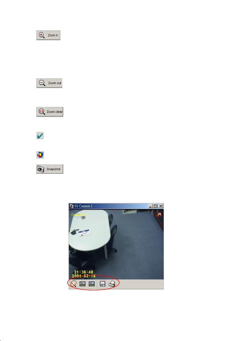
: This function is designed to zoom in (amplify) the video
display image. After you have screen zoomed in, you can
navigate the viewing area by holding down the left mouse key
on the screen.
: This function is designed to zoom out (shrink) the display
image. The video image zooms out at each click of the icon.
: This function is designed to return the image to its original
and default magnification.
Default: Pressing this will change the parameters to their default
Exit: Exits the Video Tools setting window.
: Takes a picture of the current screen and saves the image
in .bmp format. Click icons on the bottom of picture taken by
snapshot, will find more functions.
Page 44
44
: Allow user to adjust the contrast of the picture taken by snapshot.
: Allow user to change the picture taken by snapshot to be gray.
: Allow user to change the picture taken by snapshot to be its original
color.
: Allow user to save the picture taken by snapshot in Bmp or JPEG format.
: Allow user to print out the picture taken by snapshot.
4-1-1. How to Login to EZWatch Pro
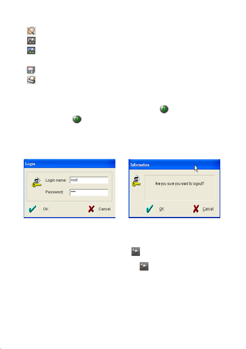
To login, click the button from the top-right corner of the Surveillance
Server program. To logout the program, simply press the same button. The
default login name and password are: Login Name: root Password:
123
Fig 4-2-1.1 Login Fig 4-2-1.2 Logout
4-1-2. Camera Configuration
To set up camera parameter, please click the icon on the bottom side of
the Surveillance Server program screen, and follow the instruction below.
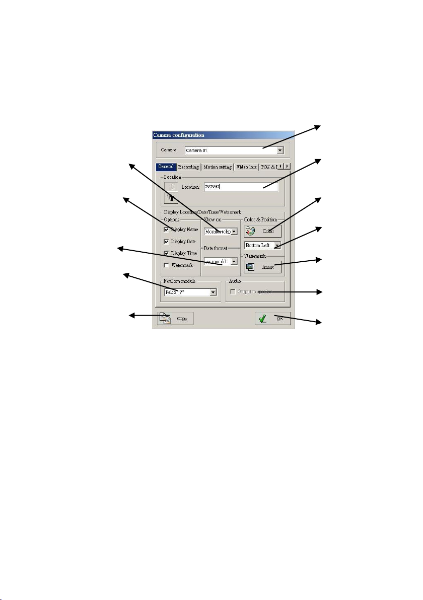
4-1-2-1.General
The section o f th e “G en eral” ta b on the top sid e C am era configu ratio n dialog is
to set up camera information display (e.g. Camera Name, Display Date,
Page 45
45
D isp lay Tim e, W ate rm ark a n d d isplay w ords’ co lo r etc.) o n the scree n . To en ter
Confirm the setting.
Camera selection
Camera location
description
Set up color of the
display words.
Set up the display
words position.
Change the
Watermark image.
Audio output for
audio listen.
PTZ camera control
protocol selection.
To duplicate another
camera setting to
current camera.
Camera date format
display selection.
Options section for
camera information
display selection.
To select if display
camera information in
playback clips or live
& playback clips.
this setup section, simply press the “G en eral” ta b on th e top o f th e “C am era
configu ration ” setu p interface.
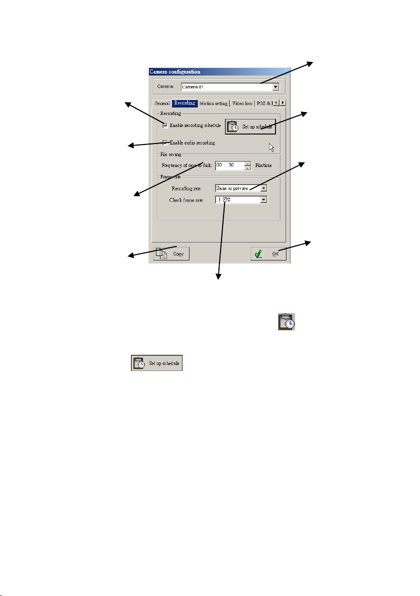
4-1-2-2.Recording
This section is to set DVR video and audio recording functions. To enter this
settin g in terface, sim ply click th e “R e cording ” tab o n the to p sid e o f the
“Cam era co n fig uratio n ”.
Page 46
46
Confirm the setting.
To set if enable the
recording schedule.
Camera selection
Click to set up
recording schedule
To setup the saving video
stream by setting
minutes for video
playback clips.
To setup the instant
recording rate.
To verify if the system actual recording frame rate is less than the “Check frame
rate” setting, or the system will restart the DVR program.
To duplicate another
camera setting to the
current camera.
To set if enable the
audio recording
capability. This
function only
available for audio
4-1-2-2-1. Set up the recording schedule
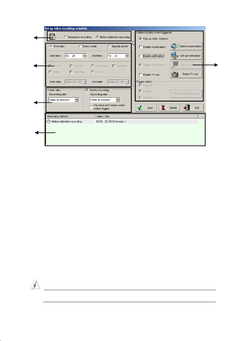
This function is to se up the DVR recording schedules and notification.
Ple a se click the “ ” icon under th e “Recording ” tab to enter the
“Set up sched u le ” interface.
Page 47
47
5 1 2 3 4
Sections Descriptions:
Section 1:
Sequence recording: To set system in sequence recording mode.
Motion detection recording: To set system in motion detection
re co rdin g m od e . To availa b le the “Prio rity recordin g” a n d the “Action to
take w hen trig g e red” settin g.
Section 2:
Everyday: To set DVR video recording schedule to be everyday.
Every week: To set DVR video recording schedule to be weekly.
Special period: To set DVR to record video in a specific period time.
Start time & End time: To set DVR recording schedule start time and
stop time. However, to set DVR to be un-stop recording for 24 hours a
day, please set start time to be 00:00 and the stop time to be 23:59.
If the time set runs over two days, set them separately. For example
if your recording time is from 5:00pm to 7:30am of next day, you
Page 48

48
should set it as two segments: 7:00 to 23:59 and 00:00 to 7:30.
When you set schedules of sequential recording and motion detection
recording, please do not schedule overlapping periods. Overlapped
periods will be executed improperly. Ex. Sequential recording is
scheduled between 3:00 and 5:00 and motion detection recording is
from 4:00 to 7:00. Because of overlap, EZWatch Pro will only execute
sequential recording from 4:00 to 5:00 and motion detention from
5:01 to 7:00.
Section 3:
Frame rate: To set th e recording fram e rate fo r the “S eq u e nce
re co rdin g ” o r “M o tion dete ctio n recordin g ”.
Same as preview: To set recording frame rate as same as the live
view frame rate.
Priority recording: This function is to set a recording frame rate
while motion detection is enabled but not triggered. The DVR will
record the video according to the setting frame rate, but if the motion
has been triggered, the DVR will start the motion detection recording
setting frame rate. (This function just enable when you use the Motion
detection recording)
File close and renew when motion detection:
If user enables this function, when the motion detection has been
trigged, the system will close the priority-recording file, and start a
new file for motion recording. Enable this function to provide user
easily search the motion issues in then evens list log. However, if
disable this function, user can review the video clips from the begging
to see how is the motion triggered, but the motion even dose not list in
Page 49
49
the evens list log.
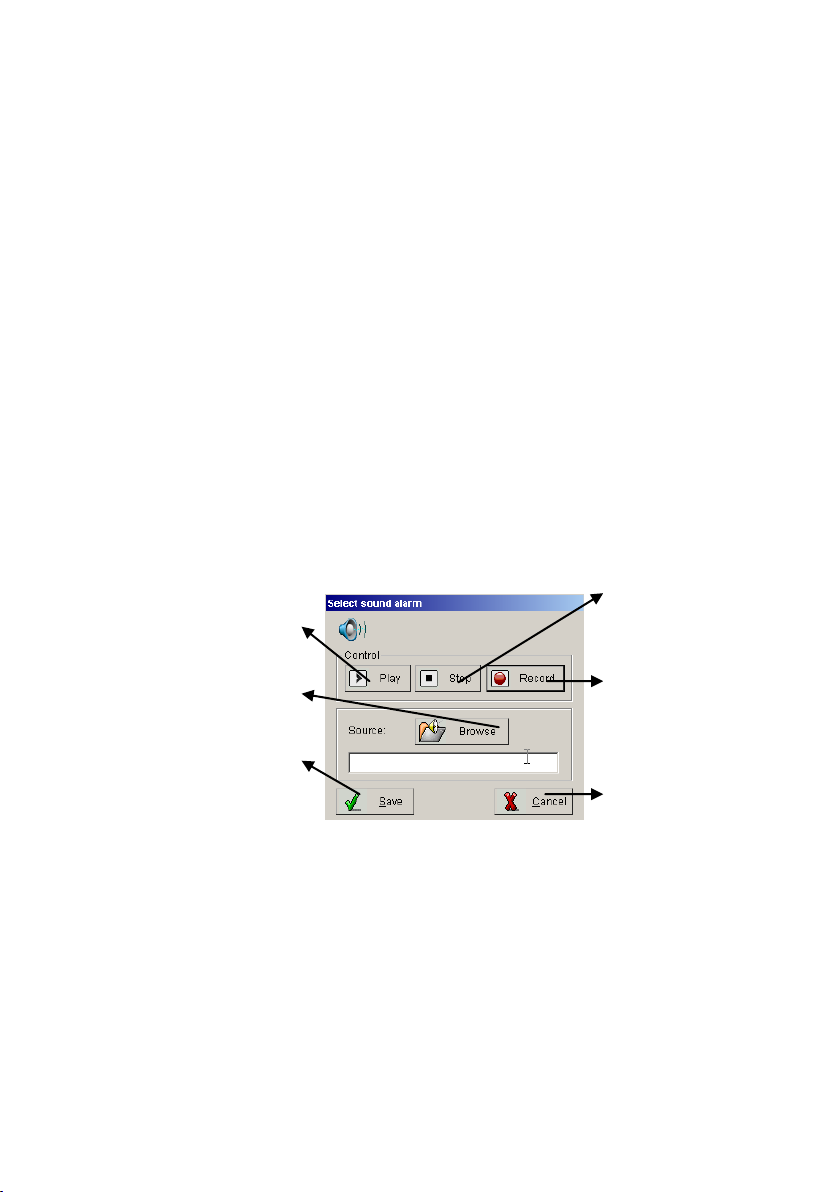
To save the setting
and exit.
To select an audio file
for alarm sound.
To play alarm sound
for testing
To exit without
saving.
To record a sound via
connected
microphone.
To stop the sound
playing.
Section 4:
Recording schedule listing window: To list the setting recording
schedule.
Section 5:
Action to take when triggered: This section is to set up DVR action
when the setting motion has been triggered. Please refer to the
introduction below for setting detail.
Pop up video window: To set if DVR pops up (enlarge) the window
when the motion is detected.
Enable sound alarm: To set if DVR sound an alarm when the motion
detection is triggered.
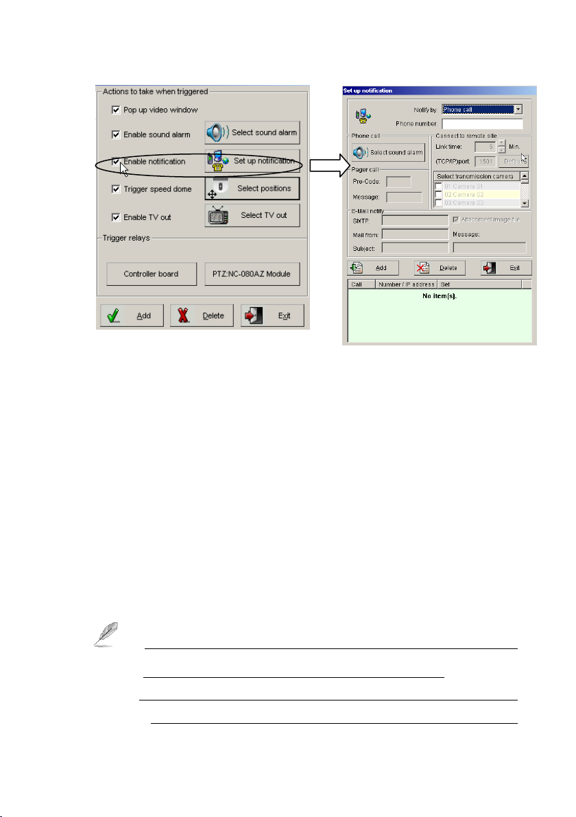
Enable notification: To send a notification to user by phone, pager,
e-m ail o r sen d ing the live im ag e to rem o te “PC EZNetwork” p rog ram
when the motion detection is triggered.
Page 50
50
Set up notification:
1.) Notify by Phone Call: When motion detection is activated, the DVR
system will dial the notification phone calls automatically by the listed
phone numbers. Please follow the step below to set up the Phone Call
notification.
Step 1: Select N o tify by ―P ho n e ca ll‖.
Step 2: Type in the phone number.
Step 3: Press th e “Sele ct so u nd alarm ” b u tto n to set the alarm sou n d
file.
Step 4: Click the ―A d d ‖ b u tton and the setting information will be
saved and list in the number below dialog box.
Step 5: Repeat step 2 to 4 to add another Phone call notification.
1. If you w ish to m ake a W ave file fo r the “Ph o ne call” notificatio n ,
and the file format must be 8000Hz, 16-bit, Mono.
2. Each phone notification could be set its unique warning audio,
and the phone connection will be disconnected after 1 minute.
Page 51
51
3. User must to use a voice modem for phone call notification.
4. If there are extension numbers in the telephone system, use
one or several commas (,) to separate the phone number and
the extension number. The number of commas required
depends on the system, so test it in advance.
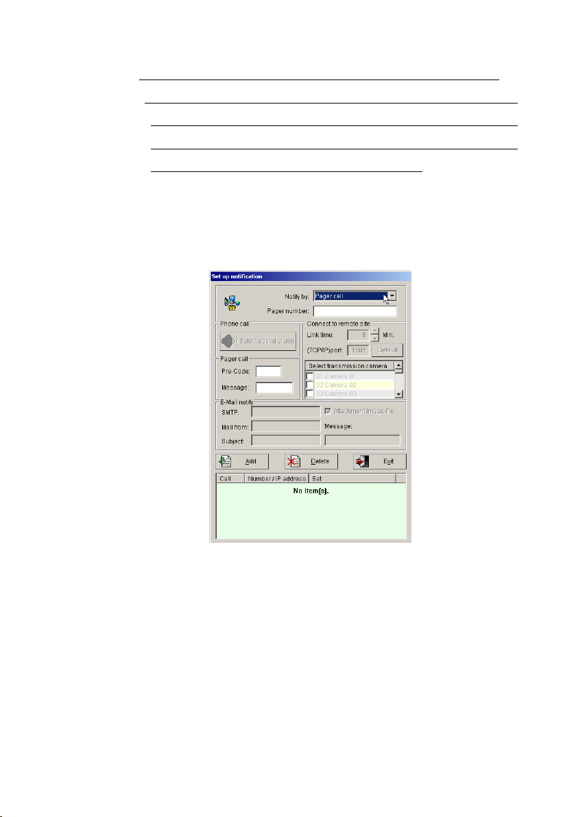
2.) Notify by Pager Call: When motion detection is activated, the DVR
system will automatically notify the listed pager numbers. Please follow
the step below to set up the pager Call notification.
Step 1: Select N o tify b y ―P ag er call‖.
Step 2: Type in the pager number.
Step 3: Type in the Pre-code or code number
Step 4: Type in the message.
Step 5: Click the ―A d d ‖ b u tton and the setting information will be
saved and list the number in below dialog box.
Step 6: Repeat step 2 to 5 to add another Pager call notification.
Page 52
52
1. Each phone notification could be set its unique warning audio,
and the phone connection will be disconnected after 1 minute.
2. User must to use a voice modem for phone call notification.
3. If there are extension numbers in the telephone system, use
one or several commas (,) to separate the phone number and
the extension number. The number of commas required depends
on the system, so test it in advance.
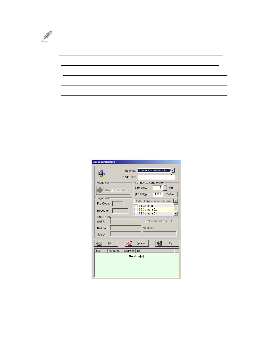
3.) Connect to Remote Site: This function is to send a live view image of
th e m otion trig ge red ch a n ne l to a rem ote netw o rk conn ecte d P C ’s
EZNetwork program (need to be open). Please follow the steps below to
set up this function.
Step 1: Select N o tify by ―C on ne ct to rem ote site‖.
Step 2: Type the rem ote PC ’s IP address or the DNS address.
Step 3: Type the minutes in ―Lin k tim e‖ section for remote PC
connection time.
Page 53

53
Step 4: Type the TCP/IP port number (Default is 1501) for the
connection.
The TCP/IP port numbers need to be same as the system
configu ration ’s TC P/IP port n um ber o f the rem ote P C ’s
EZNetwork program, or the connection will be fail. Please open
the port number for DVR from Router when you want to have the
Internet access. The detail setting of Router, please ask your local
device provider.
Step 5: Select cameras to send the live view images.
Step 6: Click the ―A d d‖ b utton and the setting information will be
saved and list in the below dialog box.
Step 7: Repeat step 2 to 6 to add another Connect to Remote
Site notification.
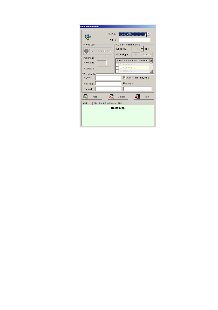
4.) E-Mail Notify: When motion detection is activated, the system will
send the e-m ail m essage to th e user’s e -mail box from e-mail list in the
dialog box automatically. Please follow the steps below to set up the
e-mail notification.
Page 54
54
Step 1: In “N o tify b y :‖ section, please select ―E-M ail N otify‖
selection.
Step 2: Type the receiving email address in the ―M ail to:‖ section.
Step 3: Type the SMTP sever address for the DVR to send the e-mail
message.
Step 4: Type the sending e-mail address in ―M ail from :‖ section.
Step 5: Type the notifying word in ―Su bject:‖ and ―M e ssag e:‖
section.
Step 6: Click the ―A dd ‖ b utton and the setting information will be
saved and list in the below dialog box.
Step 7: Repeat step 2 to 6 to add another E-Mail notification.
Enable trigger speed dome: This function is to set the connected
speed dome to move to the multiple preset positions when the
motion detection is triggered. User needs to install a speed dome to
be able to enable this function. About the speed dome installing detail
please refer to the speed dome controlling card user manual (e.g.
Page 55
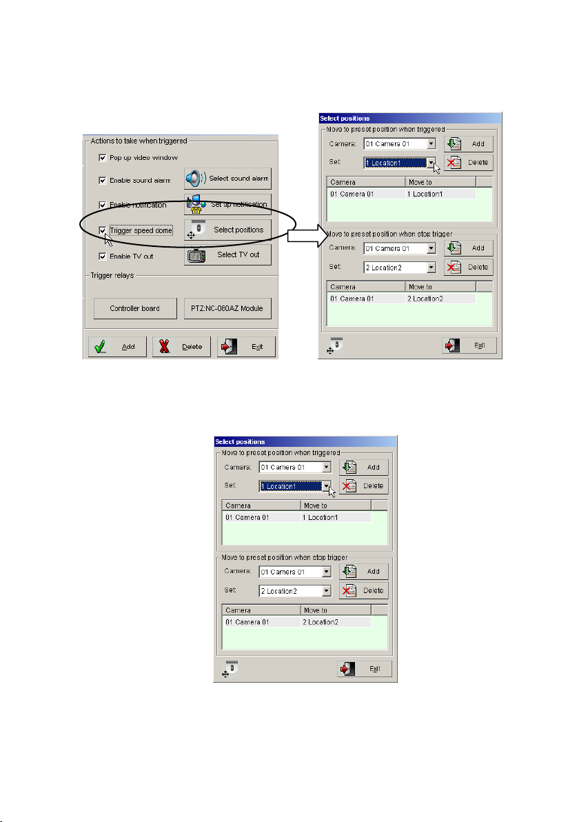
55
NC-3213 USB card user manual), also please refer to Chapter
3-2-10 Control Panel for setting the PTZ camera preset position.
Ple a se fo llo w the steps b e lo w to se t th e ―M o v e to p reset to
positio n w h e n trig g ered ‖ sectio n :
Step 1. S elect a spe cific spee d d o m e cam era from th e to p “cam era”
sele ctio n bo x in th e “M ove to preset positio n w he n trig ge red”
Page 56
56
section.
Step 2. S elect a preset p o sitio n in the “S e t” section fo r th e con n ected
speed dome moving to the selected position when the motion
detection is triggered; please refer to the Chapter 3-2-10
Control Panel for setting the PTZ camera preset position.
Step 3. Click the ―A d d ‖ button from the right side of the camera
selection box to save the settings.
Step 4. Repeat 1~3 to add one more preset position.
To set the section of ―M o ve to p re se t po sitio n w h en stop trig ger‖,
plea se use th e sam e w ay o f the “M ove to p reset p o sitio n w he n
triggered ” se ctio n setting .
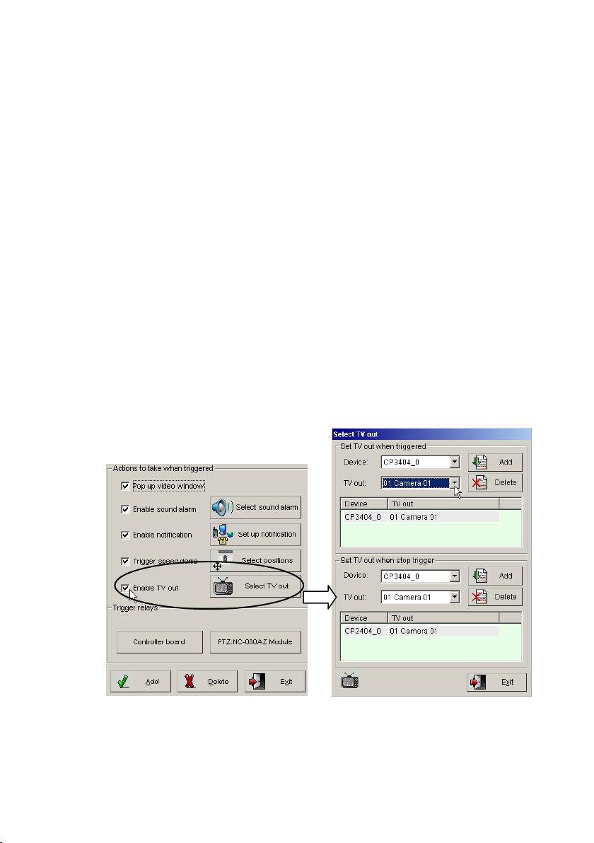
Enable TV out: While user connects a TV to the DVR cards, user can
enable this function to output a video signal to TV when the motion
detection is triggered.
Page 57

57
P le a se fo llow the ste p s belo w to set u p th e ―Set T V o ut w h e n
trig g ered ‖ sectio n :
Step1: Select the D V R card in the “D evice” sectio n.
Step2: Select the cam era in the “TV o u t” section .
Step3: Pre ss the “Add ” b utton to save the settin g.
Step4: To set a n other “TV ou t” settin g , p lease rep eat from ste p 1 to
step3.
To “S e t TV o ut w hen stop trig ge r”, p lease use th e sam e w ay of th e “S e t
TV o u t w hen trig g ered ” section setting.
Trigger relay: You can select the specific trigger relays to use and
select from Relay 01 to Relay 06. You can also trigger the relays of each
NC-080AZ module. The relay will be triggered when motion is
detected.
Page 58
58
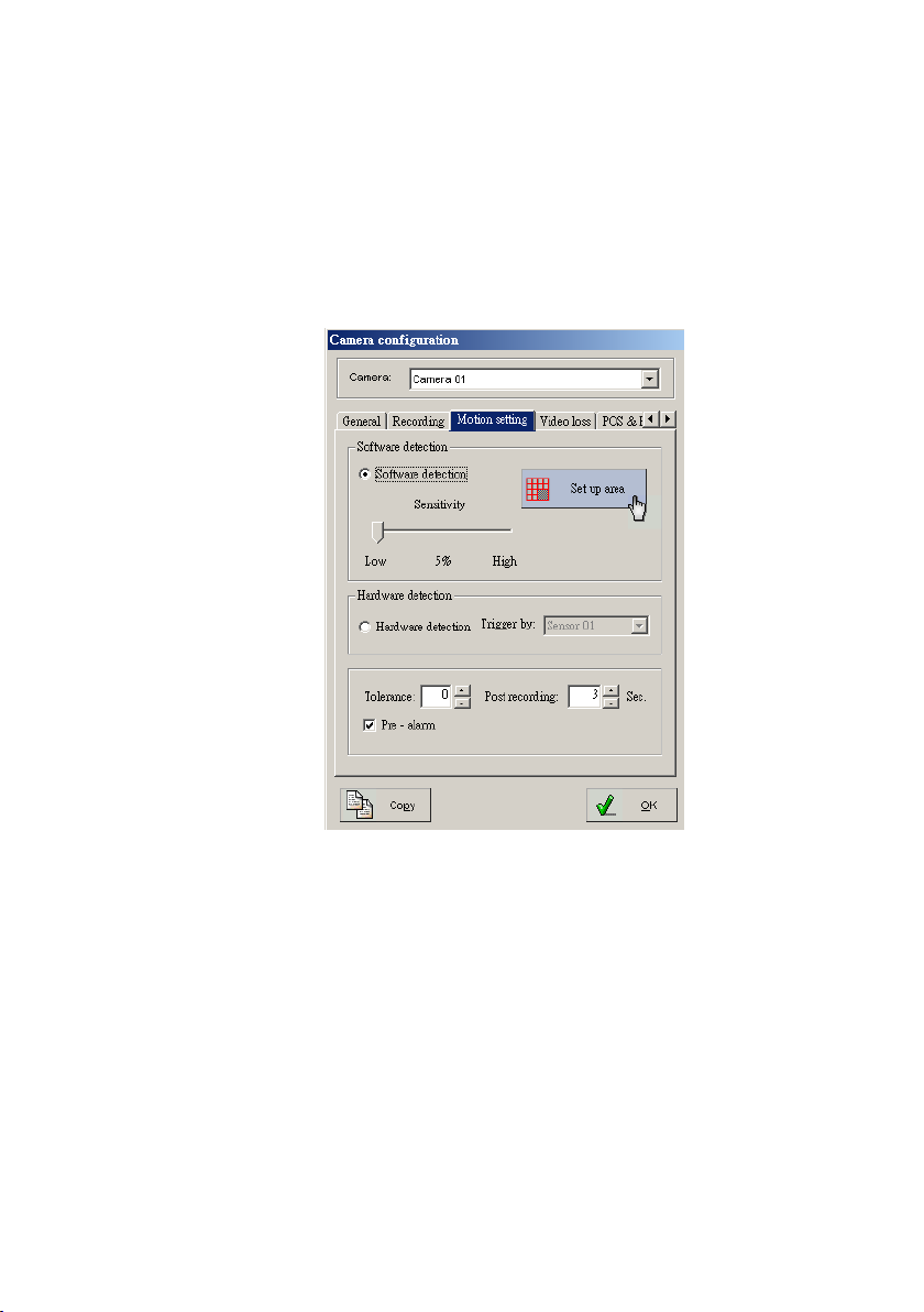
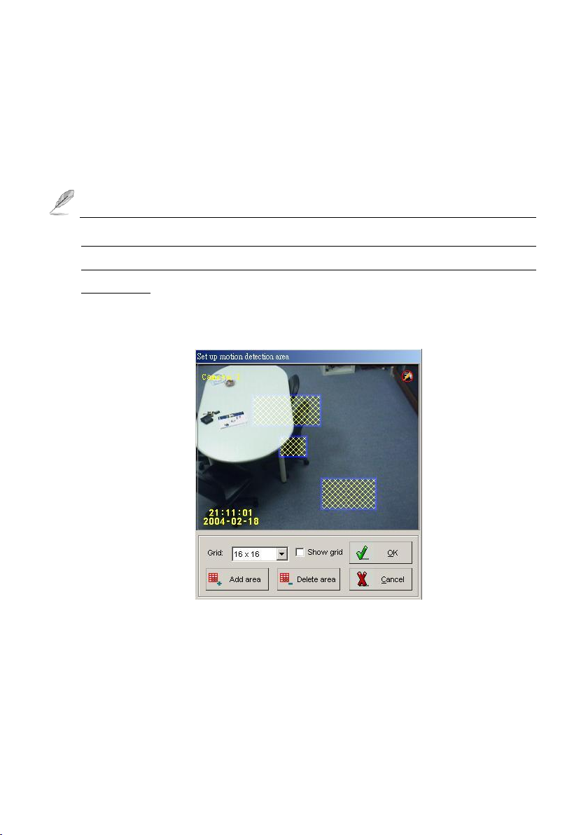
4-1-2-3. Motion Setting
This setting is to trigger the DVR to start recording when objects are moving in a
specific area. To set this function, please click on the ―M otio n settin g‖ tab from
th e “C a m era C o n fig u ratio n ”. D V R p rovid es u ser “S oftw are detection ” a n d
“H ardw are detection” fo r secu rity pro tection , to en ab le the “H ard w a re dictio n ”
function, the DVR requires installing the sensor card.
Before setting up detection, make sure that ―C a m era co nfig u ra tion ‖
―R ecordin g‖ ―Set u p S ch ed ule‖ has ―M otio n d e tection reco rdin g ‖
selected, and also the correct schedule selected, otherwise motion may not be
detected. Also, make sure that ―Ca m era co n fig u ra tion ‖ ―R eco rdin g‖ has
―En a b le R eco rdin g S chedu le ” enabled. You can confirm th at you’ve prop erly
set up the camera by inspecting the camera button number on the right toolbar –
it should now be greenish (waiting). It will turn red (recording) when motion is
detected.
Page 59
59
1.) Software detection -- Selecting software detection will save you the cost of
installing extra devices, but will cause false alarms more easily.
2.) Sensitivity of motion detection – You can adjust the sensitivity of the
motion detection. Slide the bar to the right to increase sensitivity or left to
decrease sensitivity.
The value for sensitivity should be based on unavoidable movement in the
area of the camera. For example, if you have a fan blowing, a banner may
be moving slightly. Adjusting the sensitivity properly will filter out this
movement.
3.) Set up area –Use this button to set specific areas for motion detection.
To add a specific area for detection, please follow the setting steps
below:
Step1: Press mouse left button and hold to move mouse for selecting a
specific area on the screen.
Step2: Press ―A d d area ‖ button to add the area diction.
Step3: To set more another area, please repeat the step1 to step2.
Page 60

60
Step4: Press the ―O K ‖ button to complete the areas setting.
To delete a setting detection area , please follow the setting steps
below:
Step1: Select a setting detection area by mouse right button.
Step2: Pre ss the “Delete area” to d e lete .
Step3: To delete another setting detection area, please repeat step1 to
step2.
Step4: Press the ―O K ‖ button to complete the areas setting.
If e n a b le th e “M o tio n dete ctio n re co rdin g ” in the “S e t u p sched ule ” section
of the “R e cordin g ” tap, b ut not specific a d ete ctio n area in the “S et u p area ”
sectio n of the “M otio n settin g ” ta b , the fu ll are a w ill b e th e default settin g.
Hardware detection (Optional)
You can a lso select hardw are d e tectio n . After enablin g “Hardware
detection”, select the specific sensor to use from available port. You need to
connect the sensor de vice to the port of “Sensor in” of “N e tC o m m od ule‖.
When the sensor is triggered, it will start to record and trigger the port of
relay output.
Tolerance – This function is to prevent false alarms by defining
acceptable movement. If the tolerance is set 2, video screen must change
continuously 3 times before the DVR recording.
Post recording – This function sets the time to continue recording after
motion is no longer detected; the video will be saved as a file. If the time
between one motion detection period and a new motion detection period
is less than the value in this field, the two recordings will be combined. It
will reduce the motion detection video file and notification.
Pre-alarm
Page 61
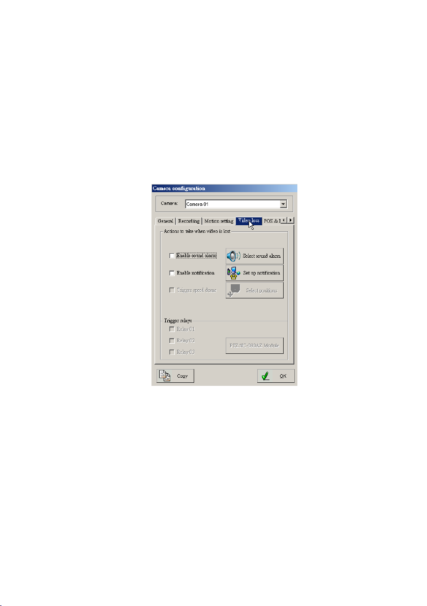
61
If u ser runs record in g b y m otion d e tectio n an d enable “Pre-alarm ‖, the
system can record videos at last 1-30 seconds (Base on the recording
rate) before event trigger base on the system RAM buffer.
4-1-2-4. Video Loss
This function is to trigger the DVR to send a notification when video losses occur.
Please click on the ―V ideo Lo ss‖ tab and follow the instructions below for the
setting.
Enable sound alarm –To set an audio warning when the video loss occurs.
Enable notification -- Each camera can have its own unique notification,
and you can set up different ways to notify someone. Please refer to page
41 to 44 for the notification setting.
Trigger speed dome – This function is to set the connected speed dome to
move to the multiple preset positions when the video loss occur. Please refer
to p ag e 4 5 to 4 6 for the detail of th e “S e lect p o sitio n ” sectio n settin g.
Page 62
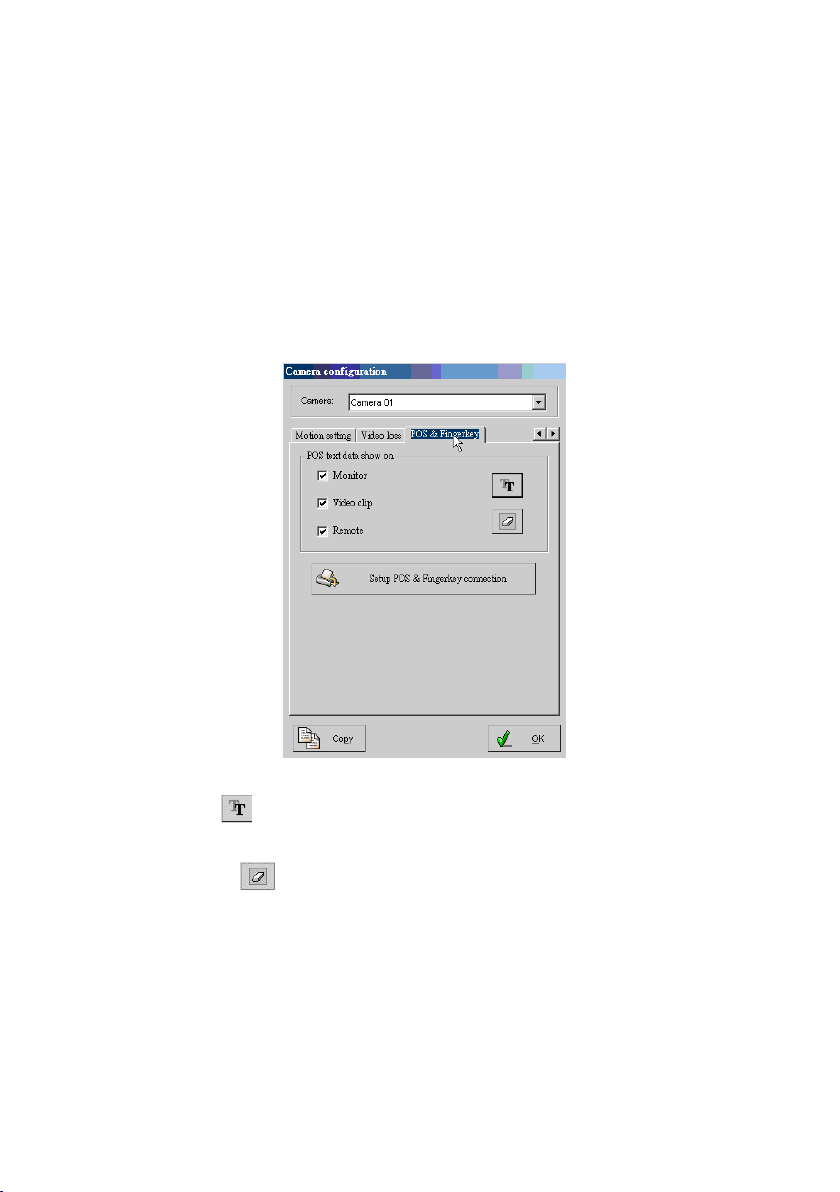
62
Trigger relays – To trigger relays when the video loss occur.
4-1-2-5.POS & FingerKey (Optional)
This function provides POS and Fingerkey text to display on the screen for specific
video clip playback searching easily. After completing the hardware installation of
PO S text in se rter system an d the Fingerkey, please p ress “PO S & Fing erkey” ta b
fro m th e top of th e “C am era con fig uratio n ” settin g and follow the instructions
below to setup the program.
Font: Click icon to specify the font size of text to past on the video
clips.
Delete: Click icon to delete the text on the.
POS text data show on: Enable/disable Monitor, Video clips and
Remote to display the POS text on the connected monitor, video clips or
remote PC.
Page 63
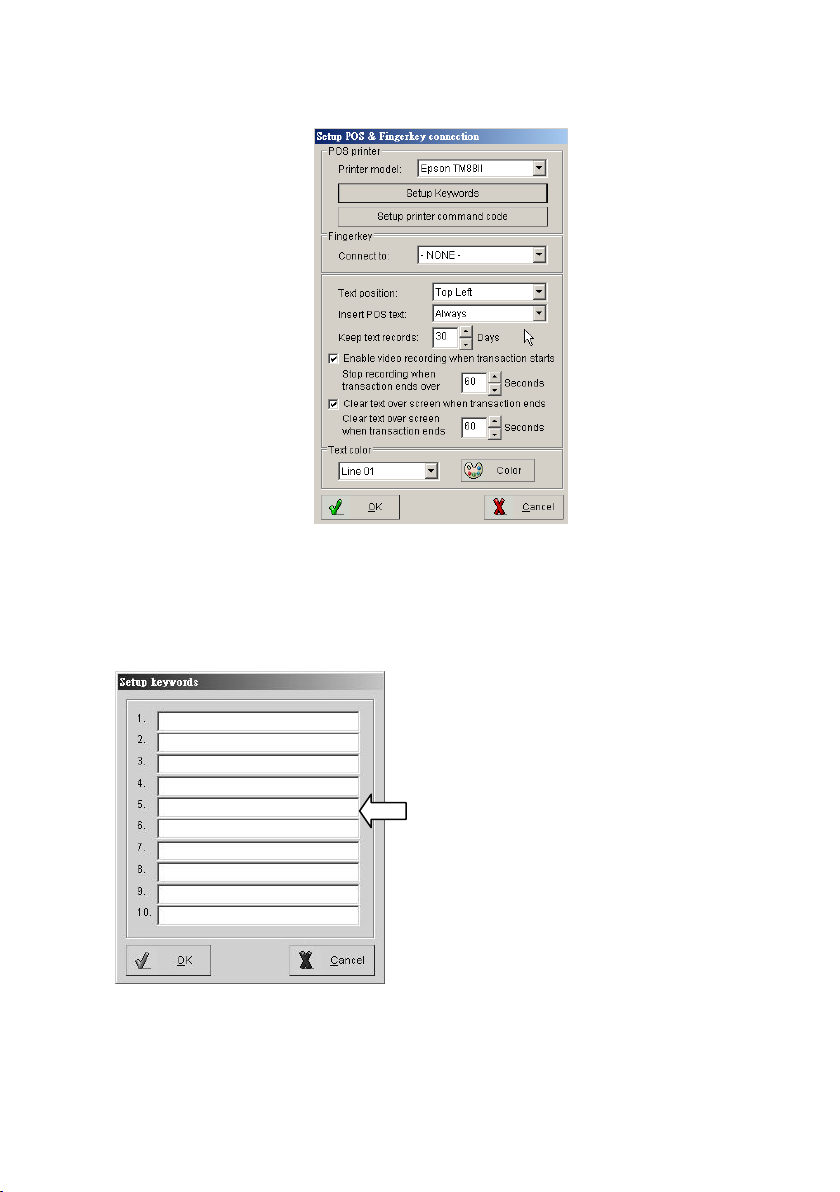
63
Setup POS & Fingerkey connection
Please type in the specific keywords in 1 to
10 column, and press “OK” button for
saving the setting.
Printer model: Select printer model, which is to be used with your POS
system.
Setup keywords: Allows you to setup Keywords for searching video clips.
Page 64
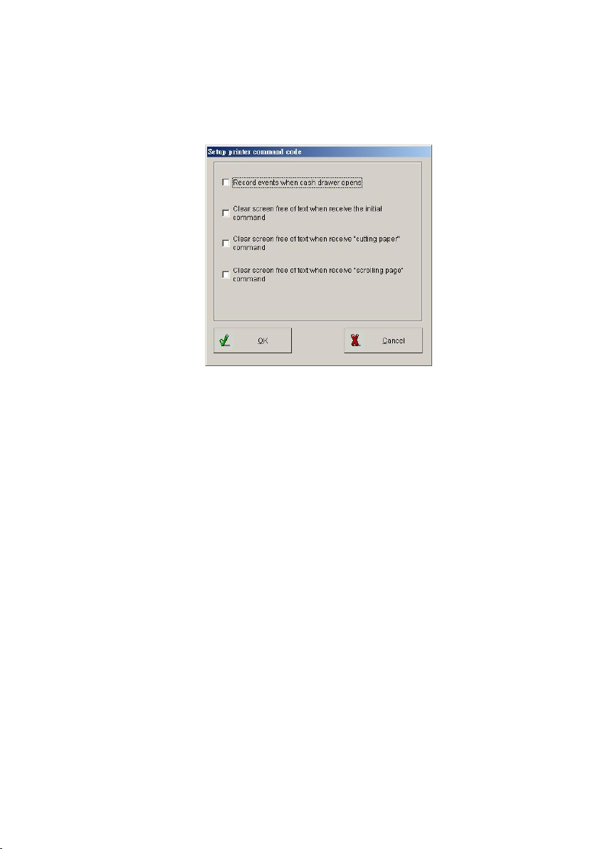
64
Setup the printer command code: The DVR is able to process certain
functions after receiving the printer command code, such as recording with
the event of opening cash draw.
Fingerkey: To select a connected fingerprint access controller to capture
the Fingerkey access record text on the video clips.
Text position: To change the display position of text by working on the
column position.
Insert POS text: Determine the status of inserted text.
Keep text records: Setup the text keeping period.
Enable video recording when transaction starts: This enables video
recording once the sale starts and specifies the time period of video
recording once the sale stops
Clear text over screen when transaction ends: This would clear/clean
up the text over the screen after the specified time period when sale stops.
Page 65
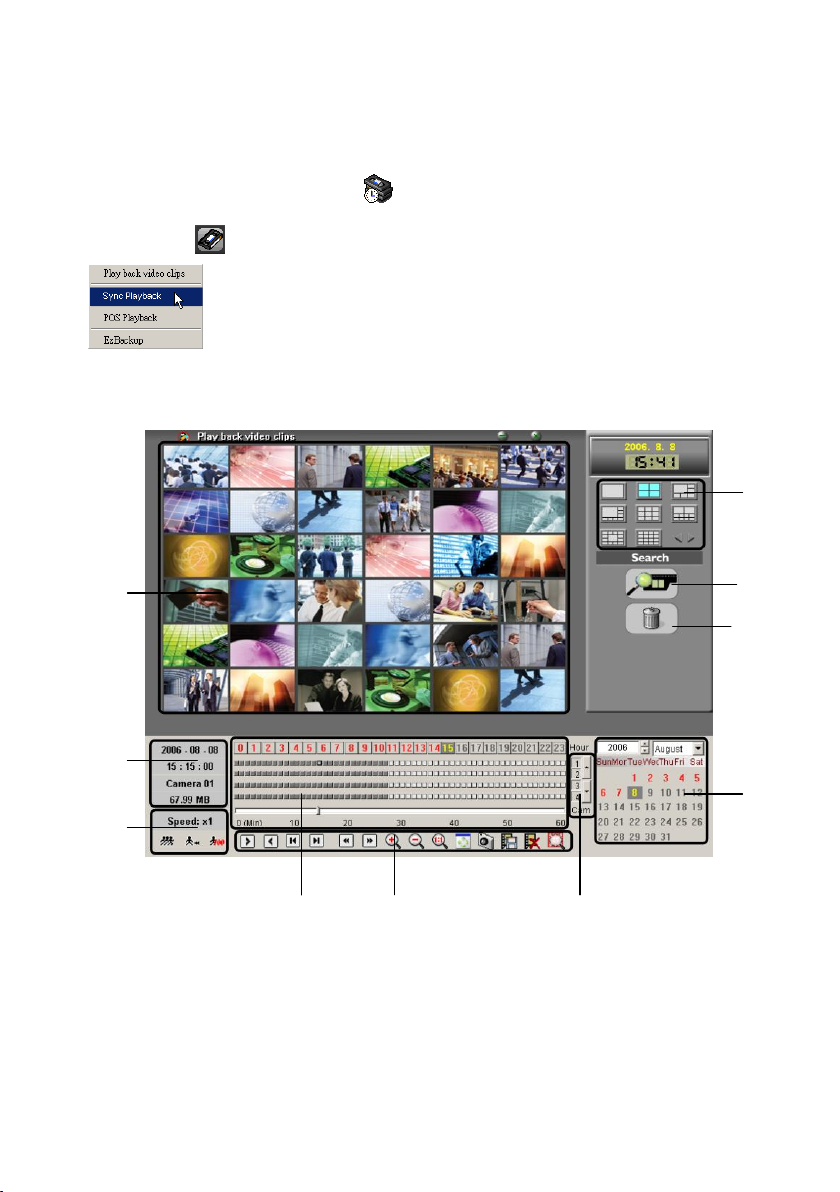
65
1
2
3 4
5 6 7
8 9
10
4-1-3. EzSyncPlayback
Clicking the ( ) ico n o n the too l b ar and select th e “EzS yncPlayb ack”
( ) to display the “EzS yn cPlayback” in terfa ce for searching video
clips.
EzSyncPlayback Overview
EzSyncPlayback Function Description:
1. Split screen display modes section: To select the split screen display
mode
2. Camera selection of the video clips: To select the playback cameras of
Page 66

66
the selected video clips folder.
3. The video clips deletion: To delete the video clips from the hard drive.
4. Video streams searching calendar: Provide user to search the video
streams of the video clips by date, the red color of the dates contain
recorded video data.
5. Cameras switch: C lip the “U p” an d “D ow n ” b u tto n s to disp lay th e vid e o
stream of the cameras.
6. Playback toolbar: Provide powerful functions for user to view and search
the playback video clips.
7. Video stream searching bar:
0~23 (Hours) selections: To search the video stream data by hours.
White/Gray color video stream blocks: White color block indicates
empty data, and gray color block indicates the block with video data.
0~60 (Min) dragging bar: To search the video steam data by
minutes.
8. Playback speed selection: Provide user to select the playback speeds to
searching easily.
9. Video stream information: To display the selected video steam
information.
10. Display screen: To display the video.
EzSyncPlayback Toolbar Description:
Play – Click this icon to play back videos.
Pause – Click this icon once to pause videos.
Play backward – Click to play video stream backward.
Stop – Click this icon to stop videos.
Previous frame – Jump to previous frame.
Next frame – Jump to next frame.
First frame – Jump to the first frame of video clip.
Page 67
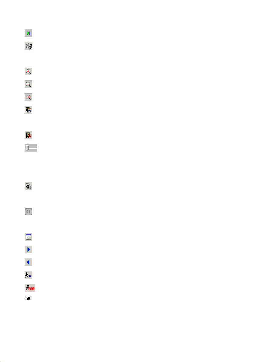
67
Last frame – Jump to the last frame of video clip.
Repeat playback – Click this icon once have the videos play back on
repeat. Click once more to cancel repeat.
Zoom in – Click this icon to zoom in.
Zoom out – Click this icon to zoom out.
Original – Click this icon to go back original video size.
Video copy – This button will copy current video clip to a specific location
for archiving . U ser could enable/disable “Copy audio data”.
Delete video – Erase video play back file.
Navigation bar – This displays the current position of the video clip and
allows users to move to different points within the clip. Left moves
backward, right moves forward.
Snapshot – Click this icon to capture the video screen as a BMP or JPEG
file.
Repeat – Click this icon once have the videos of all camera play back on
repeat. Click once more to cancel repeat.
Resize – Click this icon to resize clip.
Next video – Jumps to the next video.
Previous video – Jumps to the previous video.
Decrease frame rate – Decreases the frame rate.
Normal frame rate – Adjusts frame rate back to normal.
Increase frame rate – Increases the frame rate.
Page 68
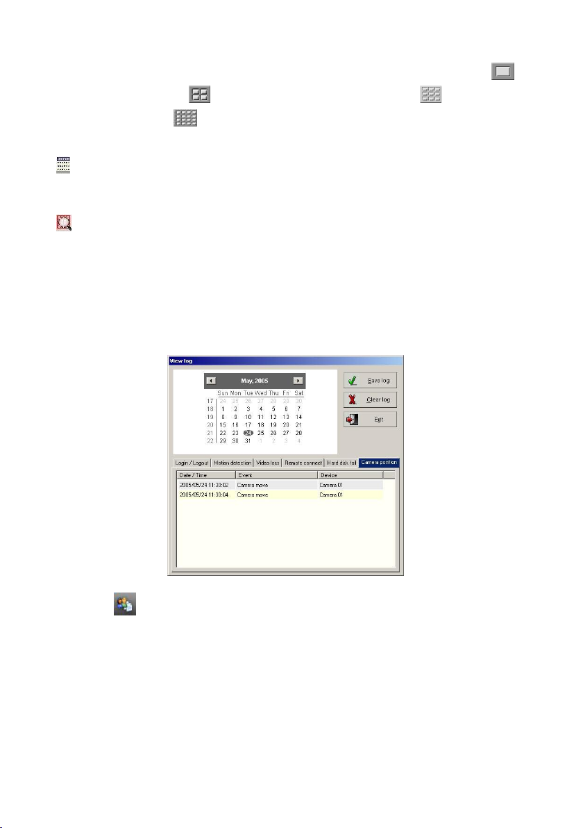
68
Screen size can be adjusted by selecting different multiple displays. Click to
view full screen; click to view videos in 352 x 288; click to view videos
in 176 x 144; click to view videos in 160 x 120.
Quick search video: To list the information of all video clips for searching
and playback.
Smart search video: To detect the change of the object in a selected region
of a recorded video clip, and list the events on the right side window. Please
follow the introduction below to perform this function:
Step 1: Playback video clips from event table of the View log directly:
Click the ico n o n the to o lb a r of th e M ain scree n to d isp la y th e “View log”
dialog.
Step 2: Press the “Motion detection “tab to d isp la y th e M o tion dete ctio n
events list.
Step 3: Search the video clips by date from the calendar.
Page 69
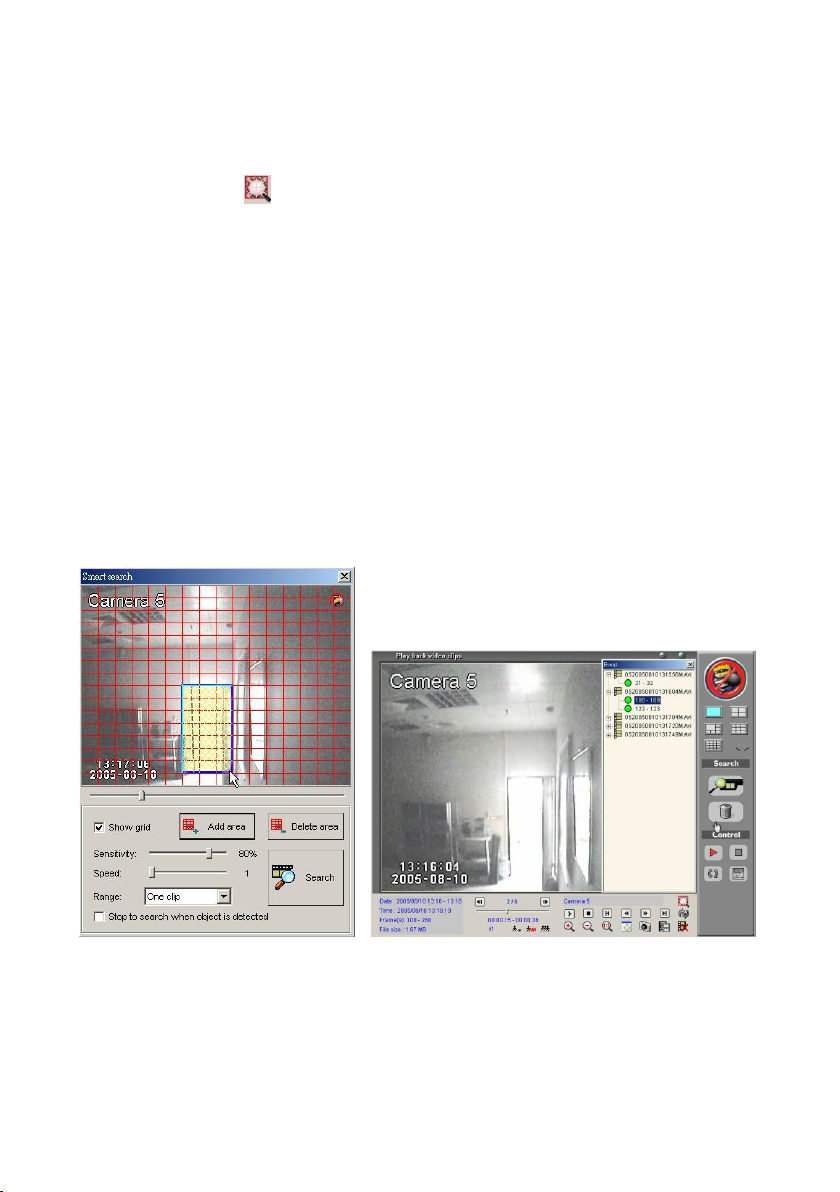
69
Step 4: Double click the desired video clips from the event list to display the
playback interface.
Step 5: Press the ico n on the play b a ck to o lb ar to d isp la y th e “Sm art
sea rch” in terfa ce (as show ing in Fig 4-1-3.1).
Step 6: Press and hold the mouse left button to select a specific searching area.
Step 7: Click the ―A d d area ‖ button to add a highlighted region. User can use
the same way to add more areas.
Step 8: A djust the “ Sensitivity “, the “ Speed “an d the“ Range “ fu n ctio n, a n d
click the “ Search “ b utto n to sta rt the sm art search function.
Step 9: As showing in Fig 4-1-3.2, the system will display all detected object
change events on the rights list window, and use can select an event to
playback.
Fig 4-1-3.1 Fig 4-1-3.2
Page 70
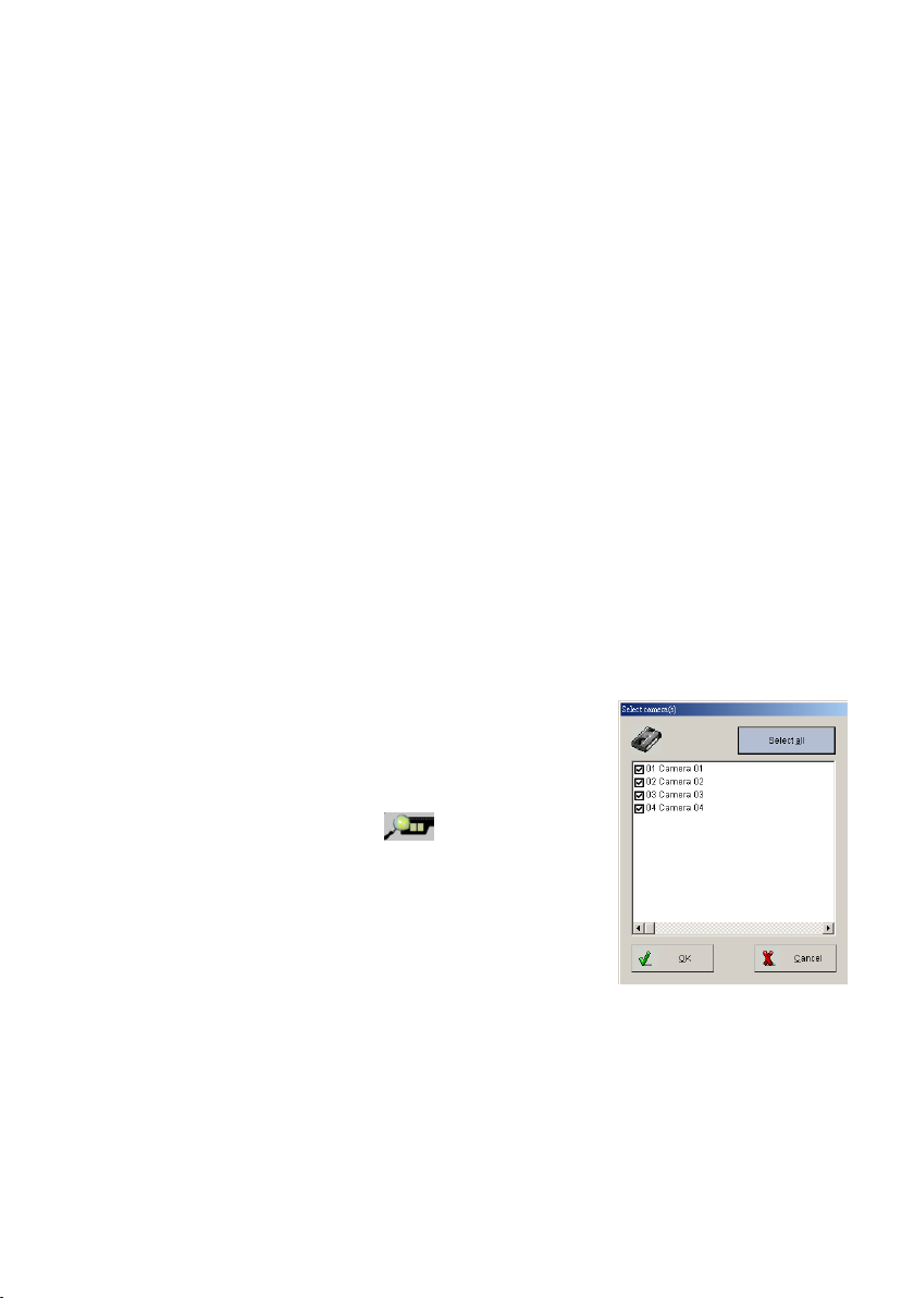
70
Function Description of the Smart Search:
Fig4-1-3.4
Sensitivity: Please base on the selected region size to adjust the
sensitivity function. If set too high of the sensitivity with the big selected
search area, the system may display very tiny changed on the list,
oppositely, if set too low of the sensitivity with the small search region,
user may easily find nothing in the result.
Speed: User can set the searching speed for the smart search function,
higher degree represents faster speed; oppositely, lower degree
represents slower speed.
Range: S ele ct” One video “or “All videos “for sm art search fu nction .
Stop to search when object is detected: If enable this function, the
system will stop the search process when object is detected.
EzSyncPlayback Basic Operation
Please follow the instruction below to use this
function:
1.) Select the playback cameras: Click the
camera selection button ( ) to display the
“Search cam era ” d ialog (As show in g in
Fig4-1-3.4), then select the desired cameras
for playback, and click the “O K ” b u tto n to
complete.
2.) Select the split screen display mode: Select a split screen to display all
cameras videos on the screen for searching easily.
3.) Select a date from the calendar to search the
video stream: Select the video stream from the
Page 71
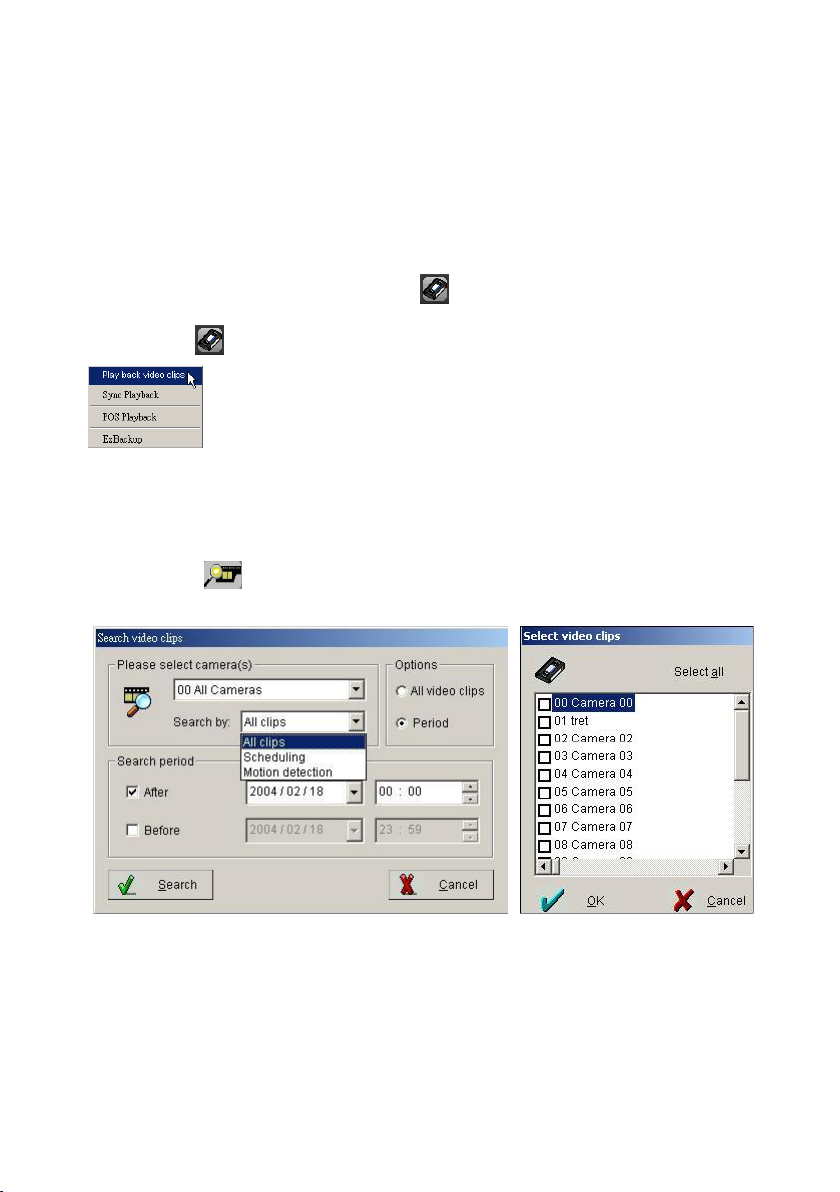
71
calendar by the order of year, month and date.
4.) Select display camera: C lick the “U p ” an d “D ow n ” b u tto n to d isp lay th e
desired cam era s’ video stream .
5.) Click a desired gray color video stream block to play: Click a desired
gray color video stream block, and click the play icon to view.
4-1-4. Playback Video Clips
Clicking the ( ) ico n o n the too l b ar and select th e “Playback V ideo C lip s”
( ) to d isplay the “S e a rch video clip s” in terface for searching video
clips.
Follow the steps below to play back videos:
Step 1: Click in the middle of right side to search for videos in database.
And you will see below window.
Step 2: Select the camera. To play multiple videos, select ―0 0 C am era 0 0 ‖.
Step 3: D ecide w hich recordin g w ay w ill b e searched b y “Options”.
Step 4: Select the recording period, then click search to find the clips among
the selected time.
Page 72
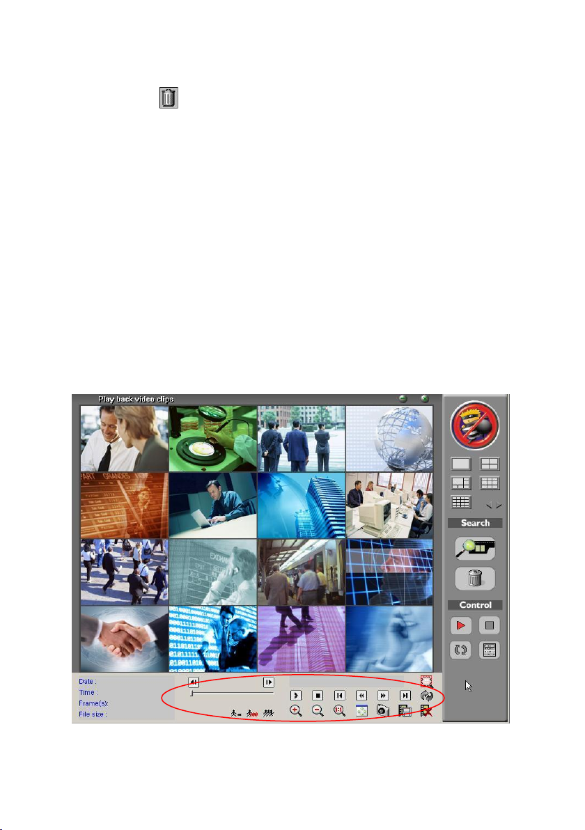
72
Follow the steps below to remove a video from your archive:
Step 1: Click on right screen to search for videos.
Step 2: D ecide w hich recordin g w ay for d e letio n b y “Options”.
Step 3: Select the videos that need to be removed.
Step 4: Select camera and time of the archived video.
Step 5: Click ―D ele te‖.
Play back Archived Videos:
At the playback screen, you can play back videos. Camera number, camera
location, time recorded, storage space, etc. will be displayed on the screen.
Double click on any video screen to enlarge a single video. Move the mouse to
any video screen to show video tool bar and information of single video (see
below picture). Double click again to restore the previous viewing screen.
Page 73
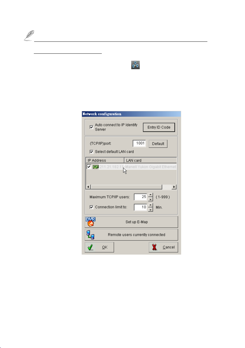
73
Please refer to the chapter 3-2-3-3 EzSyncPlayback for detail of the
Playback toolbar functions.
4-1-5. Network Configuration
Do not setup the Identify Server. This section of the software is
not functional with this version.
Set up E-Map
Enter the information for the DVR and insert a map to arrange the location of
the device. Once these devices are triggered, the information can be
transferred to a remote PC via modem or internet. The triggered devices will
be flashed on the map at the same time. Follow the instructions below to
Page 74
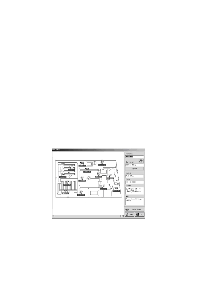
74
complete the setup.
1.) C lick” Set up E-Map “icon and below picture will be shown.
2.) Enter the DVR name into ―Site n am e ―.
3.) Click “ Map source “ icon to b rowse the map file from DVR folder and
th e n click “Update” icon after you fin d out the M ap file . (Th e m ap file
can be a BMP or JPG file.)
4.) Enter the data into “ Contact “, “ Phone “, “ Address “ and “ Note
“ tab . It w ill show the D V R in fo rm atio n on th e rem ote client PC w h e n
connecting.
5.) Select the available devices for decorating on the DVR map from
“Select device“.
6.) Move to the device and then click and drag down to the suitable location
with the left mouse key. Repeat this process for another device.
7.) Click ―Sa v e ―button to complete the setting.
Remote user currently connected
User can simply click this button to view the remote currently connected
users’ in fo rm atio n .
Page 75
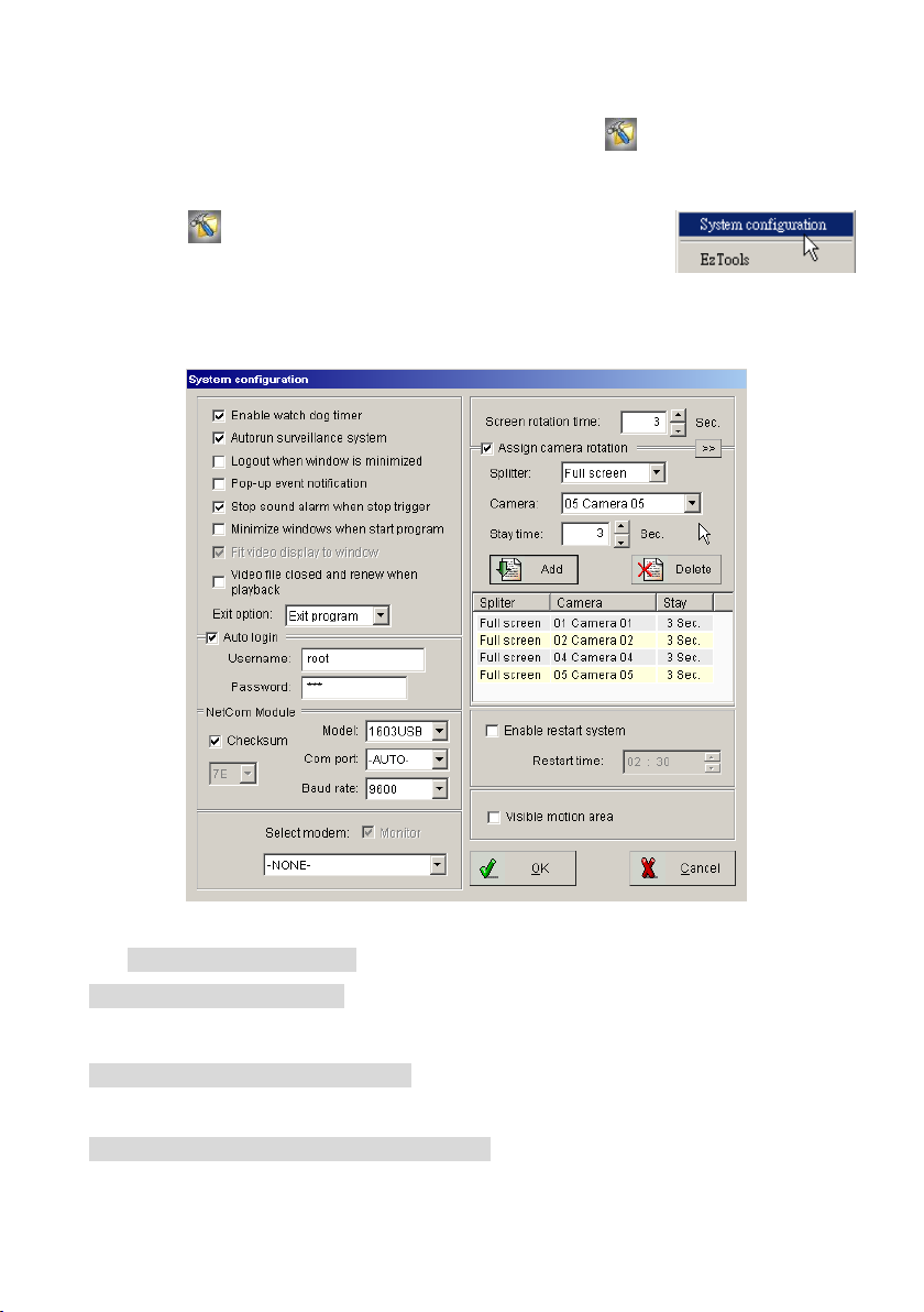
75
4-1-6. System Configuration/EzTools
System Configuration
Click the button, the system w ill d isp lay “System
configu ration ” and “EzTools” selections. To set up the DVR
system co n fig u ratio n , sim ply click th e “S yste m co n fig u ratio n ” an d the syste m
will display as below.
Function Description:
Enable watch dog timer Enable this function will reboot DVR and be back to
original setting if system shutdown caused by hardware or software problem.
Auto run surveillance system Enable this function will start EZWatch Pro
when system starts up.
Logout when window is minimized Enabling this function will logout
Page 76

76
EZWatch Pro when the software is minimized and pressing the “ ESC “ ke y o n
the keyboard will hide the tool bar of the EZWatch Pro program.
Pop-up event notification Enable this function will pop-up the event
notification message on the screen and the camera or sensor will be flashed on
the eMap when the device is triggered.
Fit video display to window will enlarge the space taken by the video display
window.
Stop sound alarm when stop trigger Enable this function, the sound alarm
will stop when trigger stops.
Minimize window when start program To minimize the video window when
enable EZWatch Pro Surveillance Server program.
Video file closed and renew when playback Enable this function, the video
file w ill close a nd renew a new on e au tom atically w h e n you click “Playb ack “icon.
You can playback the current video file without waiting till the file close. Enable
this function, it will cause the length of video file not same as your setting on
some video files.
Exit option To select PC status after exiting EZWatch Pro. Press the arrow
buttons to switch among “Exit program”, “ Turn off “, “ Log off “or “ Restart
“. For example: S elect “Tu rn off‖, the system will automatically shutdown after
exiting EZWatch Pro.
Auto login Enable this function will automatically login by user name and
password saved in the system when you reboot.
Section of the NetCom Module:
Model S e lect “3213USB or NC-320AM-I“ type for con tro l th e PTZ cam era , D /I
and D/O device. Base on which kind PTZ controller cards you plug into your DVR.
Checksum Enable Checksum or not will depend on the type of Speed dome
camera. Please refer to the manual of Speed dome camera.
Page 77

77
Com Port You m u st select “Auto” from the dra w m en u o f ―C om Po rt ―icon
Baud
rate
Switch
2400 4800 9600 192
00
S1
↓
↑
↑
↓
S2
↑ ↓ ↑
↓
when you want to enable the function of Netcom module.
Baud rate You need to select a correct Baud rate if you want to control the
Speed dome camera or P/T/Z camera from Witness DVR board (Default setting
is 9600 bps).
Dip switch of NC-3213USB Control Board:
The dip switch for the bound rate setting, please refer to the table as below:
1.) You must select 9600 baud rate, enable Checksum icon and select
“ Pelco P “ o r “ FastC am III “ or “ S D C I-2 2 0 “, w h e n you u se I-V iew ’s
FastCam Speed dome camera series.
2.) The ID 0 of Pelco “ P “ is sam e a s C am era 1 o f D V R , ID 1 same as
camera 2.
Select Modem For EZModem user or using Phone/Pager notify function should
select which modem will be used and e n ab le “M o n itor‖ below to communicate
with DVR. If u ser’s m odem and fax sh are o n e te lep h o ne lin e , u ser m u st
disab le ”m on ito r‖ when no more connection required otherwise modem will
occupy phone line always.
1.) You can select “N one” to le a ve m o d em op e n fo r oth er com m u n icatio n
software or voice calls.
2.) You m ust sele ct w h ich m od e m w ill be used and enab le “M o n itor” for
Page 78

78
EZModem user and Phone/Pager notify functions.
3.) Please contact to your local dealer for asking the model of Modem.
Screen rotation time regulates the time period of camera rotation by clicking
on the main screen. Click on the icon again to disable the rotation function.
(Default setting is 5 seconds)
Assign camera rotation To rotate the sequence of the assigned cameras,
which you want to show on the screen. There are two kinds video out rotation;
one is “Split video out “and the oth e r ―Sin gle video o ut ―. Follow the
instructions as below to set up the video rotation:
Assign camera rotation (Split video out) (For CP-1320RD and 1160RD
Deluxe only)
1.) Select the rotation way from the ―S plitte r‖ of drop down menu as the
window above.
2.) Choose the camera that will be first image on split screen at the drop down
menu ―Cam e ra‖.
3.) Enter number into ―Stay tim e‖ tag.
4.) Click ―A dd ‖ icon to save the rotation image.
5.) Repeat 1 to 4 for adding other rotation split videos.
6.) Click ―O K ‖ to complete the setting.
The rotation camera for 9 split screen, which can select 1-9 or 8-16 camera
for 9 split screen display only.
Assign TV out rotation (Single video out)
1.) Click ico n a n d then sw itch to th e setting of” TV out rotation‖
mode.
Page 79
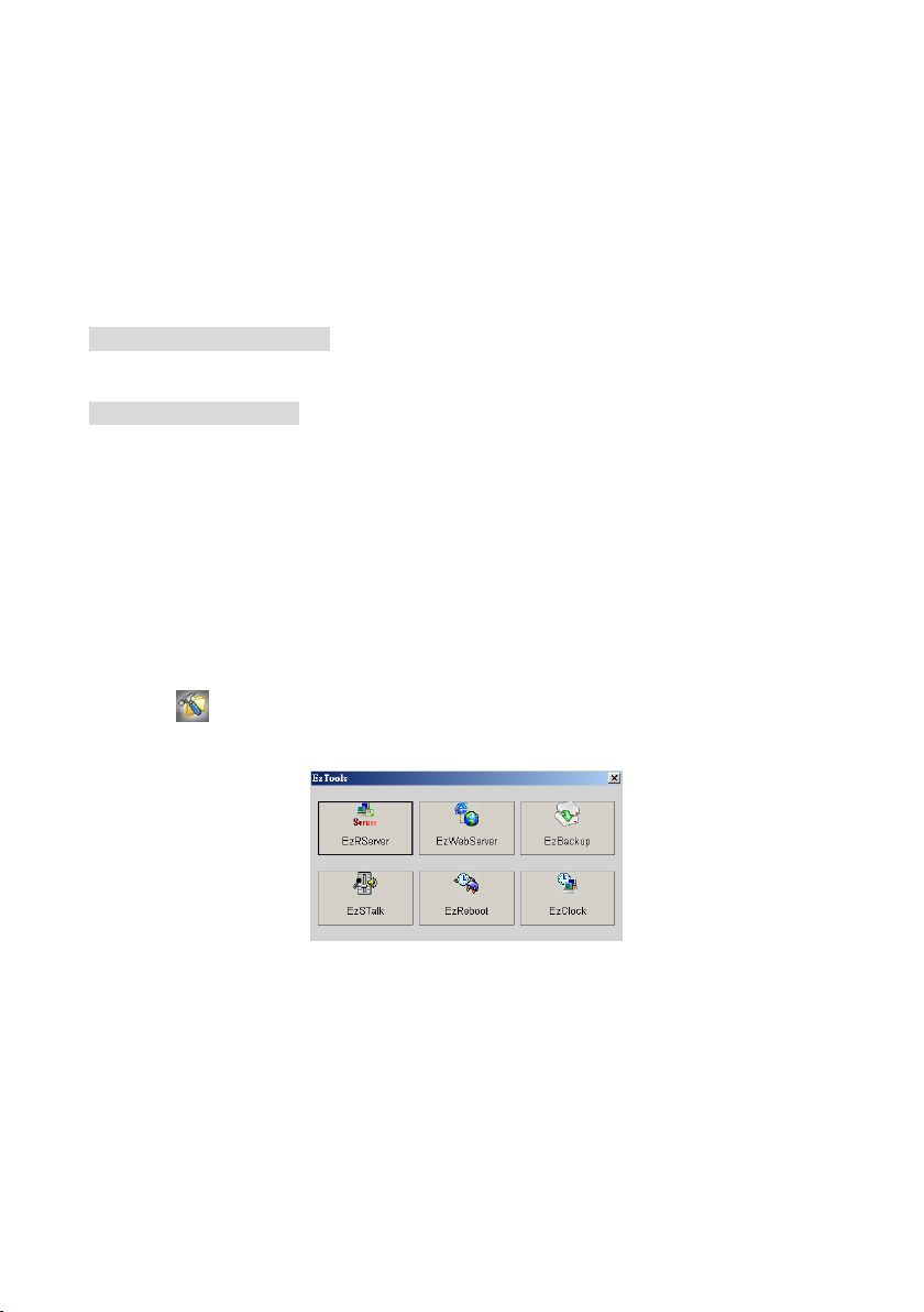
79
2.) Choose the camera, which you want to display on the TV at the drop
down menu ―Cam era ―.
3.) Enter number into ―Stay tim e‖ tag.
4.) Click ―A dd‖ icon to save the rotation image.
5.) Repeat 1 to 4 for adding other rotation videos.
6.) Click ―O K ‖ to complete the setting.
Enable restart system provide user to restarts your DVR at a set time. Using
this function stabilizes the program after a long period of usage.
Visible motion area provide user to view the setting motion detection area.
This function is only for the model of CP-1320RD and 1160RD Deluxe. To enable
this function, user need to set up the motion setting and enable the schedule
recording of motion detection in the camera configuration section.
EzTools
This function is to provide user selection the DVR main program tools without
minimize the current surveillance sever program. To enter this selection, please
click the icon, and select the EzTools selection, then the system will display
as below
Page 80
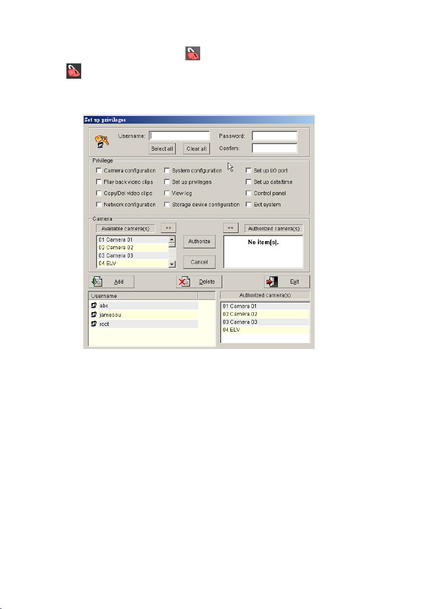
80
4-1-7. Setup Privileges
Click icon to enter ―Se t up privileges‖ interface for creating and
modifying usernames and passwords. Users will have access to different only
certain levels.
Supervisor name and password
The default supervisor name and password is listed below:
Username: root Password: 123
Please follow the steps below to modify the su pervisor’s na m e an d
password:
1.) Enter new supervisor name and your chosen password.
2.) Press ―Select all‖ (only for supervisor) and also click “>>” to authorize all
cameras.
3.) After completing the steps above, click ―A d d‖ to finish setup. Click ―E x it‖ to
leave ―S e t u p p rivile g es‖
Page 81

81
Please rem em be r rem ovin g the d e fa u lt superviso r “root”, o therw ise th ere
will be two supervisors.
Set privilege for additional users
1.) Enter username and password, enter password again for
confirmation.
2.) Select privileges.
3.) Select cameras and authorize use by clicking on ―A u th o rize ‖.
4.) After completing the above steps, click ―A d d‖ to finish user setup.
5.) To add another user, please repeat 1 to 4 steps.
1.If the supervisors password or username is lost, EZWatch Pro must be
reinstalled. All previous settings will be lost but saved videos will not be
erased.
2 Passwords must consist of 0-9 and a-z or A-Z.
3.The password is case sensitive. (PaSsWoRd is not the same as password)
Remove/modify user privileges
1.) Select the user in the username list.
2.) Click ―D ele te‖ to remove user or double-click on the username to
modify user privileges.
4-1-8. View Log
The EZWatch Pro will classify the logs by date and different events types. To
check the system logs simply click the icon and the system will display the
window as showing below.
Page 82
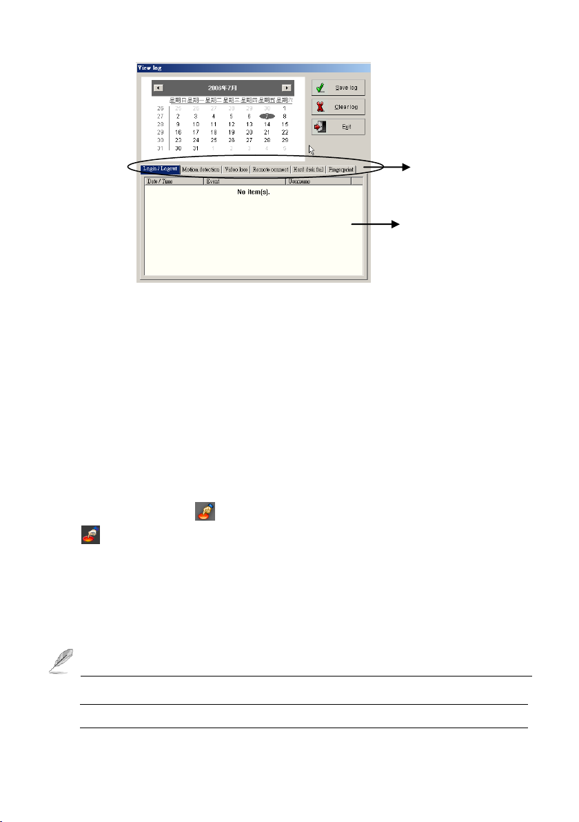
82
Evens types
Log list window
Function Description:
Save log button: To save the log list as a file.
Clear log button: To clear current log list.
Exit button: To exit this interface.
Evens types: User can simply click each type tabs to find a specific even
type’s log list e asily.
Log list window: To list each type logs.
4-1-9. Setup I/O
Click on tool bar to setup I/O configuration and parameters. Users will be able
to Setup relay, Control relay, Setup sensor, Setup Emergency call etc.
(Fig.4-1-9.1)
If you plug-in the NC-3213USB or NC-320AM-I NetCom module successfully,
all fu n ctio n s icons w ill be en a b le d . O therw ise only “setup em ergency call
“and “S et up Fin g e rprint “w ill be en ab led . Th is fu n ction can also be
Page 83
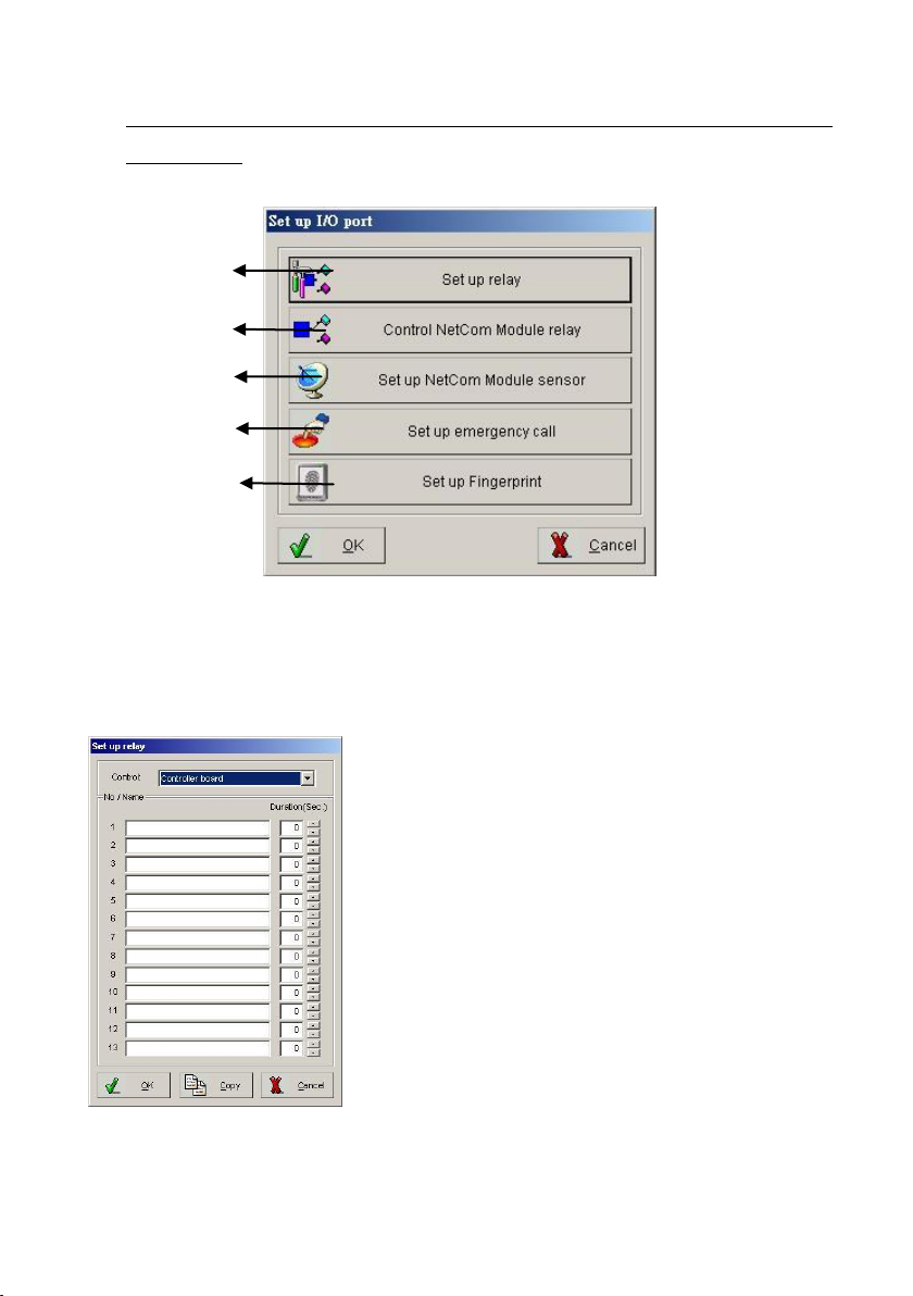
83
checked if the NC-3213USB or NC-320AM-I NetCom module has been set up
a)
b)
c)
d)
e)
successfully.
Fig. 4-1-9.1 Setup I/O port
a.) Setup relay (Optional)
The setup relay option is available when the additional relay board for the
NetCom module is installed.
Fig. 4-1-9.2 Setup relay
Page 84
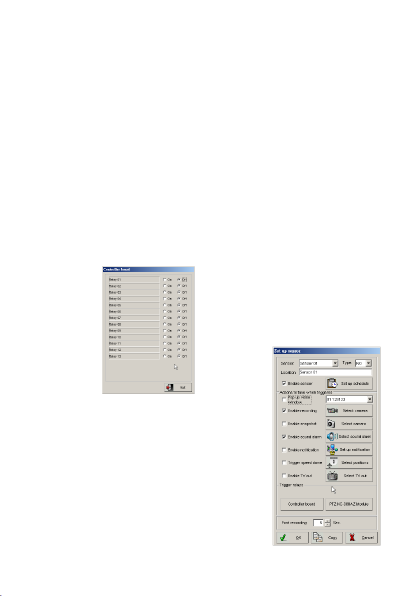
84
Function Description:
Control: You need to specify the device for setting.
No/Name: E nter “Controller name” correspon d ing to the d esired re la y
number.
Duration: En ter the controller’s w orkin g p eriod w h en relay trig ge r.
OK: Click to accept setting. Copy: Copy the parameter setting to
another relay.
Cancel: Discard changes in parameter.
b.) Control NetCom Module relay (Optional)
This function is to test remote controlling. Please click the ―Con trol NetCom
M od u le relay‖ bu tton fro m the “setu p I/O port” to enter the setup interface as
showing below.
Fig. 4-1-9.3
c.) Setup NetCom Module sensor (Optional)
Step1. Click ―Setu p N etC o m M od u le sen so r‖
button on setup I/O port, the window will
display as Fig. 4-1-9.4. Please follow the
instructions below to complete setting.
Step2. Choose a Sensor in pull-down menu.
Page 85

85
Enter location of specified sensor in ―Locatio n‖ box.
Fig. 4-1-9.4
Step3. Choose sensor type (NC or NO) in ―Type‖ box.
Step4. Select ―E n able reco rding ‖ and/or ―E n able sn ap sh o t‖ and/or
―En a b le sou nd alarm ‖ and/or ―En able n otifica tion ‖ and/or “Trigger
speed dome” and “Enable TV out” con fig u re th eir corresponding
options to the right.
Pop up video window: This function is to set up the corresponding camera
of the sensor, and enable this function to pop up the setting camera while
the sensor has been triggered.
Enable recording: select camera you want to record when emergency call
is pressed.
Enable Snapshot: select camera to snapshot when emergency call is
pressed.
Enable sound alarm: You can set each camera to have its own unique
alarm sound.
Enable notification: See details on how to set up Notification on page 37.
Trigger speed dome: See details on how to set up position on page 41.
Enable TV out: Please refer to page 44 for detail “En a b le TV o ut” setting .
Step5. Select the specific trigger relays to use from Relay 01 to 06(Back
Panel). It also can trigger the relays of each NC-180AZ module.
Step6. En ter” Post recording” tim e to co n tin u e record in g a fter sensor is
triggered.
Step7. Click “O K ‖ to complete.
d.) Emergency call
This function is to set up emergency notification when the panic button is
pushed, simply click the icon and follow the setup interface instruction to
configure the emergency call feature which are sound an alarm, notify someone,
Page 86
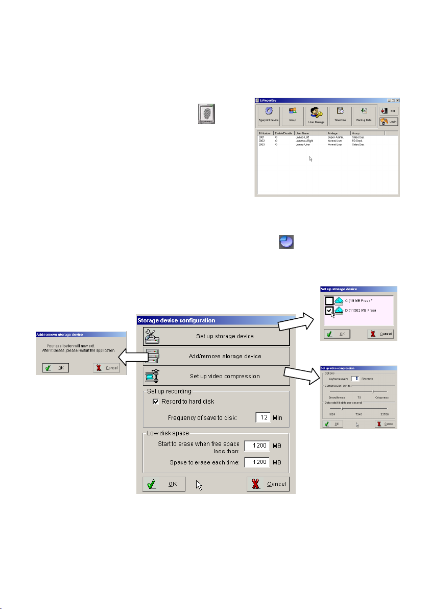
86
start recording or show live video feeds on connected TV sets.
e.) Fingerprint Access Control
While user connected the fingerprint access
controller, user can simply click the icon.
For detail of the Fingerprint Access Control,
please refer to the fingerprint access
controller user manual.
4-1-10. Storage Device Configuration
This function is to set up system configured storage device and video saving
compression rate.
Storage device configuration interface description:
Page 87
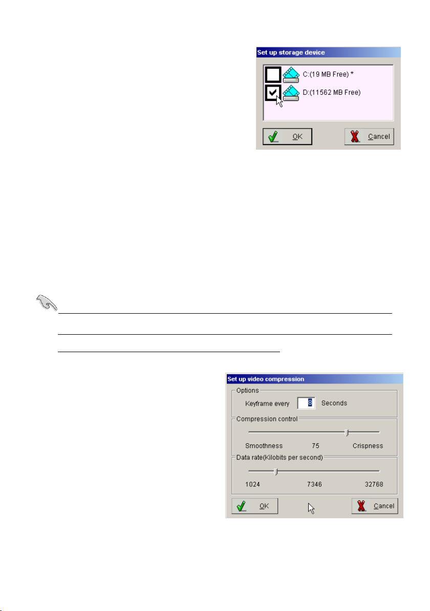
87
Set up storage device: This button is to
enable the system configured video
storage. To enable the configured device,
sim ply che ck the device a n d click th e “O K ”
button to complete. Selects your video
storage location (C:\, D:\, etc). Since C:\
usually stores O.S., it is best to store the video files on an alternative hard drive
if one is available.
Add/remove storage device: This function is to detect the new storage device,
but the DVR system need to be restart. This button must be clicked after a HDD
drive is removed or added to your system. Otherwise, the program may not find
playback video files. Clicking this will close your application, please remember to
restart it.
Please perform this function if you find that the playback function is working
abnormally. Running this function could repair video clip and rebuild the
Database of video clips and reindex the database.
Setup Video Compression: This
section provides you with the ability to
control video recording compression and
quality. You can control the video
quality with the compression control
slider. Move the slider to the right for a
crisper picture or move the slider to left
for smoother video playback. Note:
The CPU will use more power when the
slider is set higher. The data rate slider bar controls the amount of data that is
Page 88
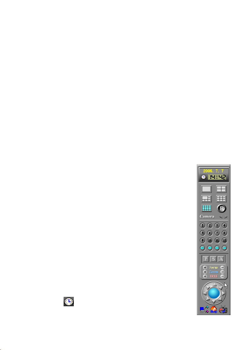
88
recorded to each video clip. The further left the slider, the fewer images that it will
record. If the setting is set lower, you can have more data or video time recorded
and visa versa.
Space to erase each time: This section is to set up the DVR system erasing the
image storage space size each time.
Record to hard disk & Frequency of save to disk When you enable ―R e co rd
to ha rd d isk ‖, your video clips will be saved to hard disk every few minutes
automatically. For example, if Frequency is “5 minutes”, video clip s w ill be
saved every 5 minutes. You can choose from anywhere between 5 and 30
minutes. Using this option can minimize video clip loss under abnormal conditions,
such as a power outage. If you enable this, it is recommended that you add a fan
for the hard disk because of the additional heat that will be generated. If you
disable this function, video clips will be saved in memory and saved
to disk based on your settings in Camera configuration Recording
File. However, if the system shuts down abnormally, all clips not
saved to disk will be lost.
Start to erase when free space less than Will start to free space
on your hard disk when only a certain amount of space is left on
your hard disk. Older files are erased first.
Space to erase each time This specifies the amount of disk space
to free when the above limit is reached. Older files are erased first.
As an example, if 1200 MB is entered, 1200MB will be erased when
the limit is reached.
4-1-11. Video Control Panel
Clock Setting
Page 89
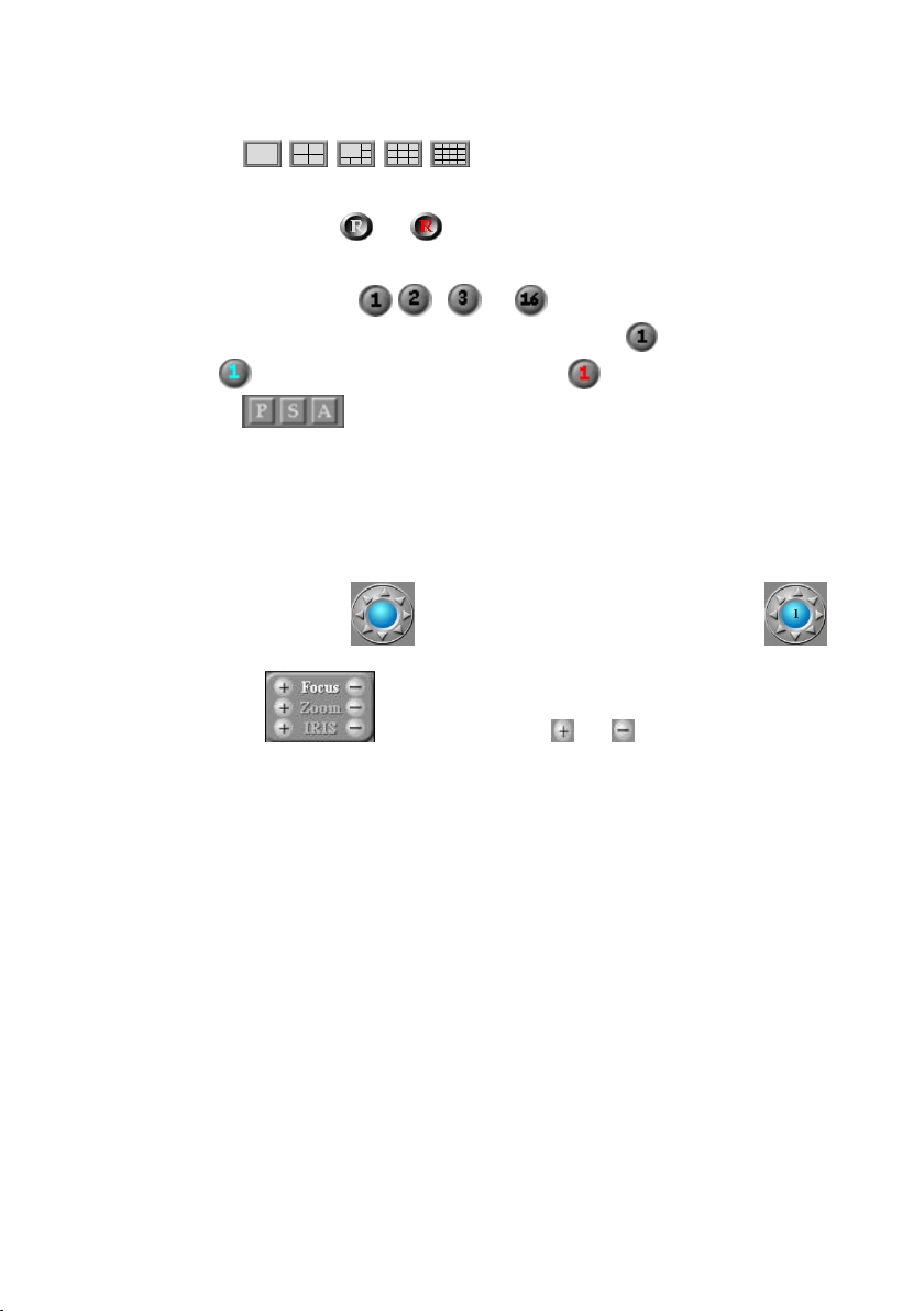
89
To set up the DVR system display time clock.
Display Modes
Provide different display mode to view all connected cameras easily.
Display Modes Rotation
Click to rotate the channels in split viewing mode automatically.
Camera Display selection , , …
The chan n els sele ctio n b u tto n s for “norm al live vie w in g ”, “schedu le
prerecording ” a n d “recording the v iew im age ”
P S A buttons (Optional)
PTZ camera control functions, user needs to install and configure the PTZ
camera and its controlling card to enable this function.
―P ‖ b u tton : To set the PTZ camera “Preset Po sitio n”, to set up th is fu n ctio n
please follow the setup steps below.
Step 1: Blue circle in the icon and select a PTZ camera (e.g. ).
Step 2: Use the icon and click on or to adjust the
parameters.
Step 3: U se the icon’s d irectio n arrows to adjust the camera aiming position.
Step 4: Pre ss th e “A” b u tto n a n d p ress “Sto p sw ivel”.
Step 5: Press th e “P” b u tto n to en ter the “Preset Po sitio n” setting in terfa ce.
Step 6: Typ e a locatio n n am e an d p ress the “Set” b utto n , a n d click the “O K ”
button to complete.
Page 90
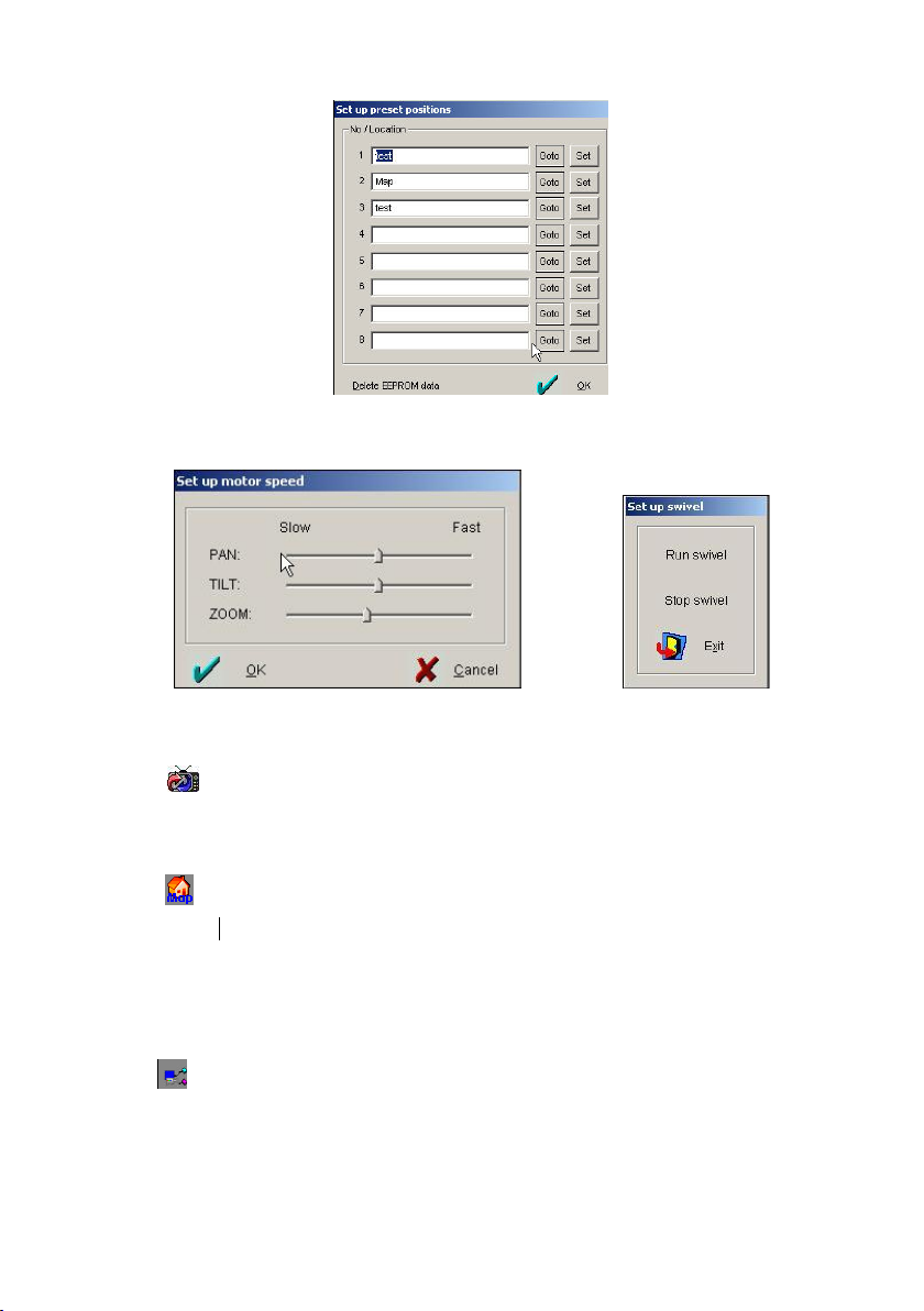
90
―G o to‖ b u tton : To test the setting PTZ camera if aim to the preset position.
―S ‖ b utton : To set the speed for this camera pan, tilt, and zoom.
―A ‖ b utton : To adju st the P T Z cam era “A u to scan” m odes.
TV out
Click this icon to rotate videos or pop-up the on TV. (For single video out) You
can choose which camera(s) and how many seconds will show on the TV.
E-Map
Click this iconh to show the information and map of DVR. When the sensor and
camera is triggered that the icon will be flashed and video will pop up the TV out.
If you use the dual monitor to display, the map will be shown on another monitor
automatically.
Relay
Click this icon to set up I/O sensor of NC-180AZ Receiver module.
Page 91
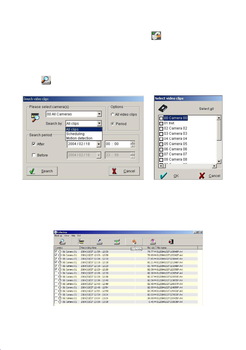
91
4-2. Back up system-EzBackup
This chapter will show how to back up video clips to another storage device from
your saved database.
Follow the steps below to back up videos
1. Click in the top of left side to search for videos in database. And you will
see the window below.
2. Select the camera. To play multiple videos, select ―00 C am e ra 0 0 ‖.
3. D ecide w hich recordin g w ay w ill b e searche d b y “Options”.
4. Select the recording period time and date. Click search to find the clips
among the selected time, and the system will display the window as
below.
Page 92
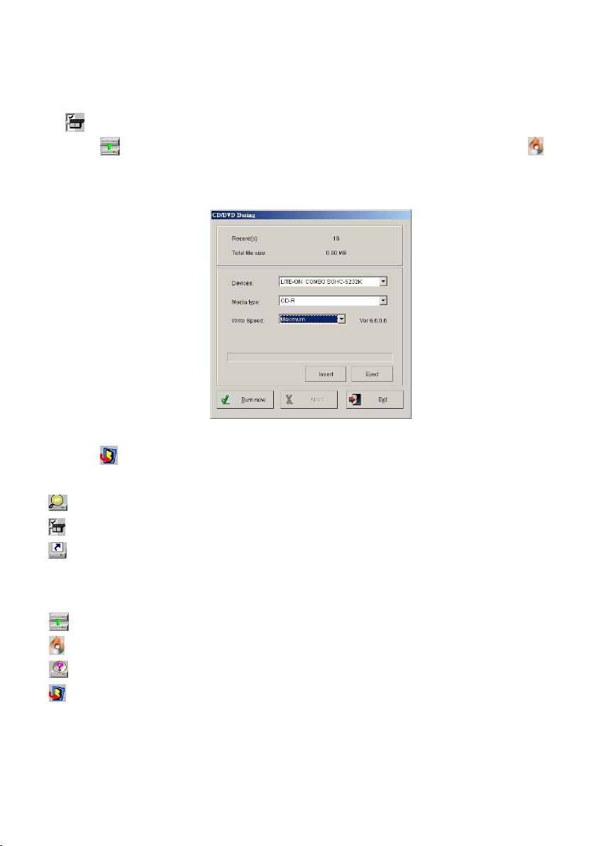
92
5. Select video file, which you would like to have by manual. Or you also can click
to select /remove selection all video file.
6. Click to back up video clips to another HDD drive. Or you also can click
icon and you will see below window to back the video clips into
CD-RW/DVD+-RW. Click the ―Bu rn N ow “bu tto n for start b ackup video files.
These backup video clips can be searched by I-Vie w ’s EzPlayb ack progra m .
7. Click to complete backup.
Video tool bar on backup screen
Search – Click this icon to search video files.
Select – Click this icon to select/remove all video clips to back up video clips.
Create backup shortcut – Click this icon to paste the video clips which has
been selected to the other storage devices; such as CD-RW/DVD+-RW or
HDD.
Back up video clips – Click this icon to back up video clips to Hard Disk.
CD Burning – Click this icon to back up video clips CD-RW or DVD+-RW.
About - Press to see the program version.
Exit –Exit the video backup setting window.
Page 93
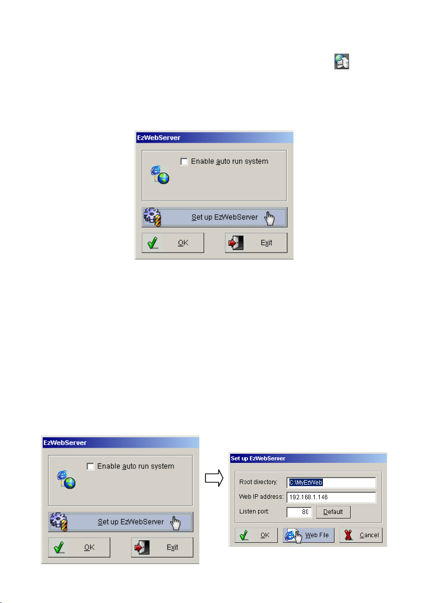
93
4-3. Web Browse Server – EzWebServer
Fig. 4-3.1 EzWebServer
Fig.4-3.2 C lick the “Set up E zW ebServer” to display “Set up EzWebServer”
This function is to provide user for remote monitoring with IE browser via
internet. Please follow the instruction below to set up this function.
Setup in local host DVR sever:
Step 1: Please click the “W eb B ro w se r S ever – EzW ebS erver” b u tto n to enable
this function.
Step 2: Click ―E n ab le a uto run system ‖ and ―H id e w in dow ‖ to
automatically enable the EzWebServer when start the EZWatch Pro system
every times.
Step 3: Ple ase click the “Se t u p EzW e b S erver” button a n d fill out th e “W eb IP
ad dre ss” sectio n . For d etail abo u t th e fix IP add ress, ple a se conta ct you r ISP
provider.
Page 94
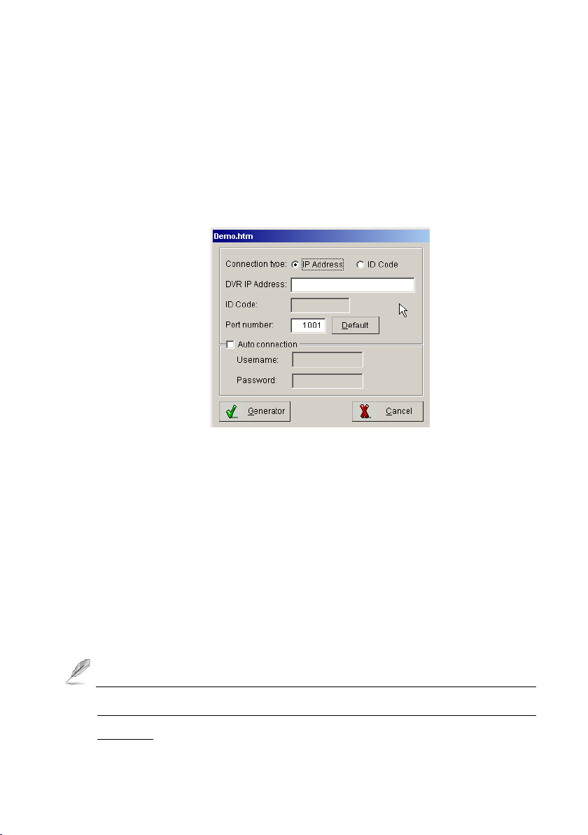
94
Fig. 4-3.3 “Demo.htm” setting interface
Step 4: Please click th e “W eb File ” b utto n a n d fill o u t th e in fo rm atio n in e ach
sectio n of th e “D e m o.h tm ” in terfa ce , the n click the “G enerator” button to
complete the settings.
―D em o.h tm ‖ S etup in terfa ce se ctio ns d e scrip tion :
Connection Type: To S ele ct use “IP A dd ress” connectio n o r “ID C ode” (For
Dynamic IP address connection) connection.
DVR IP Address: If user selects “IP A d d re ss” connectio n typ e , ple ase fill
the DVR IP address in this section.
ID Code: If u ser selects “ID C od e ” con n e ctio n typ e , p le ase fill the ID code in
this section
Port number: Please type the port number for remote connection.
Please make sure the setting connection port is not used by PC program
commonly, or the connection may be collided with other PC application
program.
Page 95
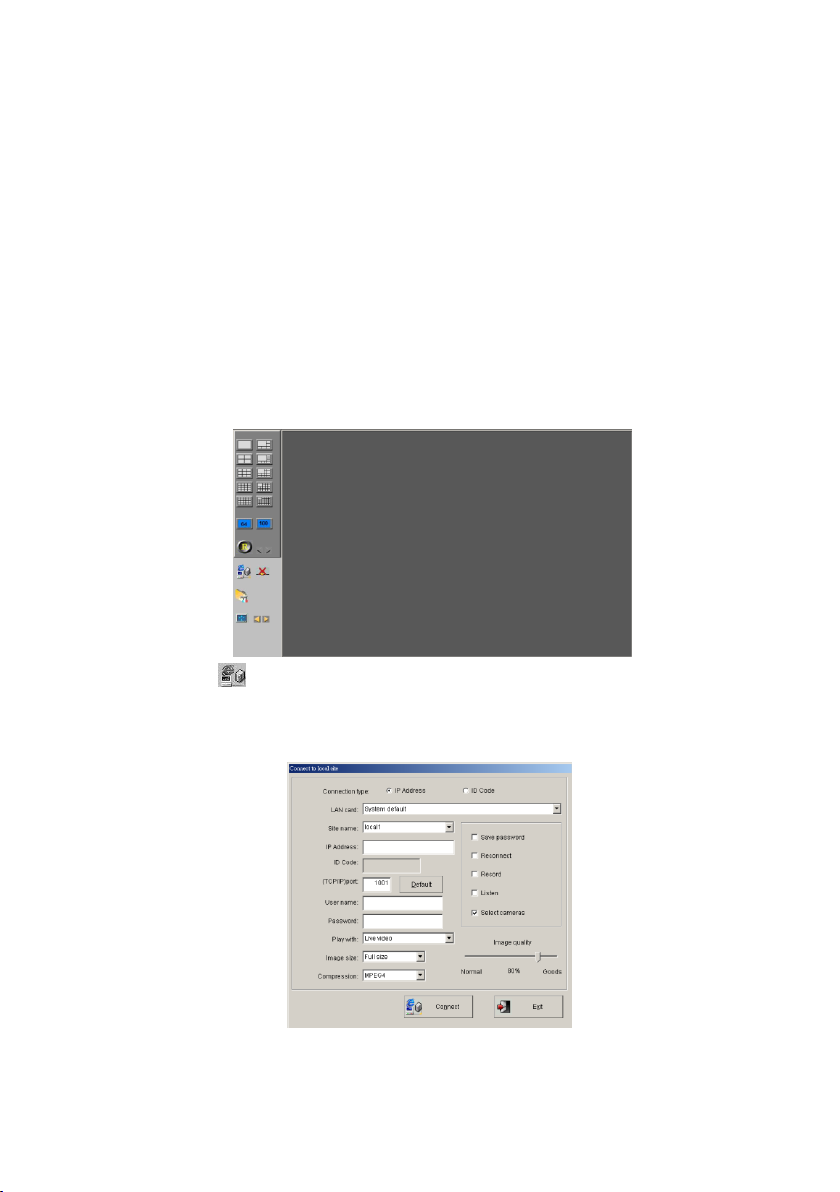
95
Auto connection: Enable this fu n ction an d type in th e “U sernam e” an d
“passw ord to allo w rem ote PC to set up rem ote connecting this DVR
automatically.
Remote client PC setup:
Step 1: Click IE Browse from the Remote client PC, and then enter the IP
address of Local DVR Server.
Step 2: Please allow the ActiveX program to install on your PC when the
ActiveX pop-up, and the screen in IE browser will display as below.
Step 3: Click icon from the right side control panel to connect the Local
D V R S erver, an d the scre en w ill d isp la y th e “C o n nect to lo cal site” settin g
interface.
Page 96

96
Step 4: S im ply g ive a nam e in “S ite n a m e ” a n d typ e in the D V R IP a d d ress or ID
cod e, (TC P/IP) p o rt n u m b er, Lo g in “U ser nam e” and “Passw ord ’, the n p ress the
“Con n e ct” b u tto n to start the con n e ctio n.
Page 97
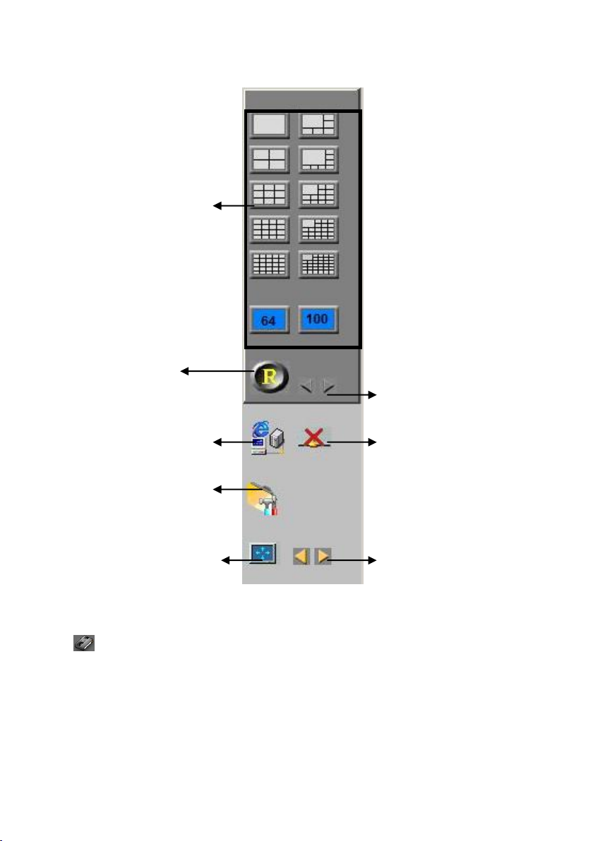
97
Browser Viewing Tools Function Description:
Display mode selections
Sites Rotation
Remote DVR connection
setup
Select Audio enable and the
PTZ camera control
To enlarge the selected
channel in split display
mode
To select channels in Full
size display mode
To disconnect the connection
The channel selection
buttons.
4-4. LAN Play Back Video Clips – EzLanPlayback
This chapter introduces how to use the EzLanPlayback program via the Local Area
Network (LAN) connection. Before start to use EzLanPlayback program, please
make sure that the file folder (e.g. ClipPro folder) of the EZWatch Pro is shared to
network users, and follow the instruction below to start.
Page 98
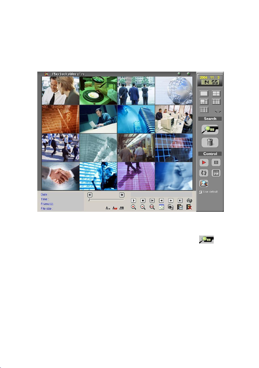
98
Step 1: Please go to the path: Windows ―Start‖ m en u ―Prog ram s‖
EZWatch Pro, and click the ―LA N p la y ba ck v id eo – EzLanP la y b ack ‖ to start
the program as showing below
Play video clips from a default folder:
Step 2: To use default lo cal video clip s file folder, sim ply click the “ ” icon o n
the right side control panel, and the system will display a video clips searching
dialog as showing below.
Page 99
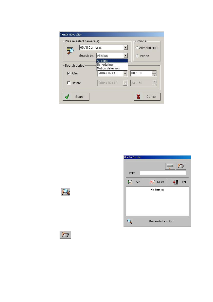
99
Fig 4-4.1 Search video clips
Step 3: Select the desired camera and specific date, then click the ―S e a rch‖
button to search the video clips.
Step 4: The system will automatically playback if the program finds the video
clip s, or it w ill d isp lay a m essag e o f “N o V id eo C lips”.
Play video clips from the local
specific folders:
Step5: To select a specific local folder of the
vid e o clips, sim ply u nch eck th e “U se d efau lt”
box and press the icon on the right side
control panel and the system will display the
“Search vid eo clip s” dialog as sh ow in g
below.
Step6: Click the icon to select a specific video clips folder for playback,
and p ress the “Add” button to ad d the selected fold er path fo r vid e o clip s
searching list, and repeat this step to add more video clips folder path on the
searching list. Press the ―R e-sea rch vid eo clips‖ button to finish the adding.
Page 100
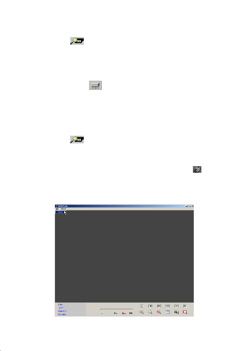
100
Step7: Click the “ ” ico n a n d rep eat the Step3 and Step4 above again to
play the specific local folder video clips.
Play video clips from the network sharing folders:
Step8: To play the video clips from the remote network sharing hard drive
fold er , please click th e “ ” ico n to disp la y th e ne tw ork h ard drive setting
dialog, follow the dialog instruction and type the specific directory of the network
sharing folder to add the path in the searching list. To add more network sharing
folder, please repeat this step again. Press the ―R e-sea rch vid e o clip s‖ button
to finish the adding
Step9: Click the “ ” ico n a n d rep eat the Step3 and Step4 above again to
play the network sharing folder video clips.
4-5. Play Back Video Clips – EzPlayback
This function is for user to play back video clips in fast and simple way. Please go
to the path: Windows ―Sta rt‖ m e n u ―P rog ram s‖ EZWatch Pro, and click
the ―P la y b ack vid e o clips – EzP layb ack‖ selection to start the program
 Loading...