

EZWatch EZBR-0519HD User Manual
EZ-BridgeLT-HD
™
High Performance Point to Point Wireless Bridge System
▫ Surge protected Ethernet and Power for ultimate
reliability. Shielded CAT5 cables to protect
against EMI.
▫ Achieve up to 15 Mbit/sec speed; 20Mbps for
5GHz version
▫ Link up to 3 miles with good line of sight
▫ Plug and Play Simple Installation
▫ Best security available (WPA)
▫ Field Proven Wireless Technology

2
Note: We highly recommend connecting the EZ-Bridge™ power sup-
ply to a surge protected outlet or an Uninterruptable Power Supply system. We also recommend using only shielded and grounded CAT5 cable between the antenna and the POE Inserter and between the POE
Inserter and the router or PC. This will help prevent damage from lightning and electrical surges caused by lightning.
DANGER! Avoid Powerlines!
You Can Be Killed!
When following the instructions in this guide to install the antenna take
extreme care to avoid contact with overhead power lines, lights and
power circuits. Contact with power lines, lights or power circuits may be
fatal. We recommend to install antenna no closer than 20 feet to any
power lines.
Safety: For your own protection, follow these safety rules.
▫ Perform as many functions as possible on the ground
▫ Do not attempt to install the antenna on a rainy, windy or
snowy day or if there is ice or snow accumulation at the install
site or if the site is wet.
▫ Make sure there are no people, pets, etc. below when you are
working on a roof or ladder.
▫ Watch out for any power lines which may be overhead, under-
ground or behind walls., keeping safely clear of them with the
antenna, ladders or any tools.
▫ See appendix for FCC RF exposure guidelines
Recommended Tools: Pliers, Screws and screwdriver if
mounting to a wall. NOTE: You should be familiar with using
tools such as these before attempting installation of the antenna.
You should be comfortable with working on a ladder.
Getting Started
It is recommended that you setup the EZ-Bridge™system in a
single room to get acquainted with the operation of the units before installing outdoors. Connect 1 EZ-Bridge™ to your router, switch or com-
puter and just power up the other EZ-Bridge™. Make sure the anten-
nas are pointing away from each other for best results. After powering
up each unit, you should be able to communicate with each unit by typing it’s IP address into a standard browser.
3
Qwik Install
STEP 1: Choose a mounting location with good line of sight to the re-
mote location. The supplied bracket can be mounted to a wall or to an
existing pole up to 2” diameter. If only short distances are needed, the
antenna can be mounted inside a building.
TECH TIP: Microwaves travel in straight lines and they lose
strength quickly when going thru buildings and trees. If there are
objects in the microwave path, then useable distance will be reduced. If
the target unit is less than 1 mile away then you won’t have to worry too
much about a couple obstructions but if over 1 mile and there are some
obstructions in the microwave path, then the performance will be reduced.
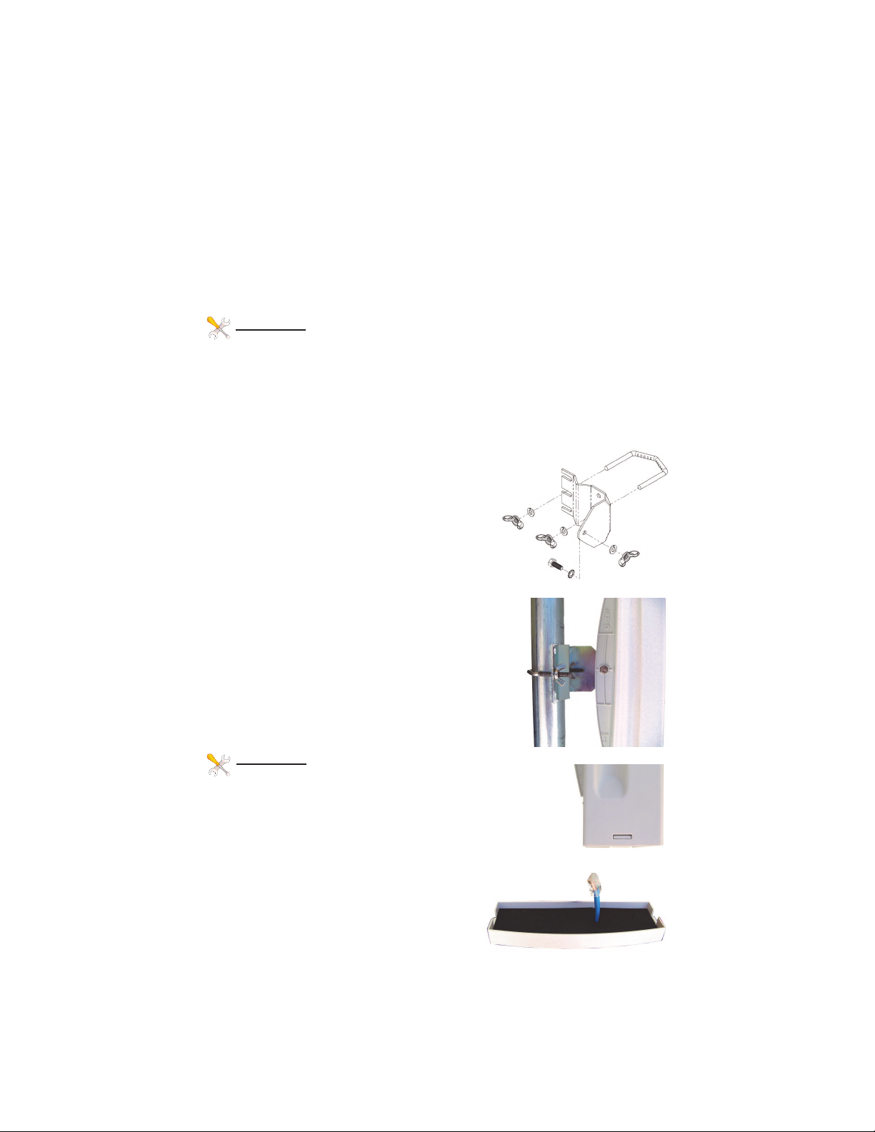
STEP 2: Mount the Bracket
To mount to a wall: The supplied u-bolt is
not used and the bracket is screwed directly
to a wall using customer supplied screws.
To mount to a pole: Use the supplied U-Bolt
and wing nuts. Make sure to use a lock
washer at each wing nut. Tighten wing nuts
evenly by hand. Use pliers if additional tightness is needed.
STEP 3: Mount the antenna housing to the
bracket. Put the hex head bolt thru the housing
back fin. Put the star lock washer so it is between plastic housing and metal bracket. Install
wing nut with lock washer. Adjust desired tilt angle and tighten wing nut. Use pliers if additional
tightness is needed.
TECH TIP: Because of the specially de-
signed wide beamwidth antenna, pointing is not critical and simply pointing in the general direction of the
receiving antenna will yield great results.
STEP 4: Remove the antenna bottom cover by using a
coin or house key or screwdriver to push
in one of the side snaps and then remove
the cover.
STEP 5: Route the shielded CAT5 cable

4
through the bottom cover and plug into the RJ45 Jack inside the unit.
Keep the black gasket material in the bottom of the cover to help keep
out dust and insects.
STEP 6: Route shielded CAT5 cable from the antenna into the building.
Always create a strain relief near the antenna so the cable is not pulling
directly on the antenna. Use the CAT5 strain relief hook feature built
into the housing back fin. The
Ethernet spec allows for a maximum cable length of 100 meters or
about 328 feet.
STEP 7: Install a CAT5 cable between the POE Inserter input and
your router, switch or PC. Attach the
CAT5 cable from the antenna to the
RJ45 output port of the POE Inserter. Plug the POE Inserter into a
surge protected AC power source to
power up the EZ-Bridge™
Software Settings
We strongly recommend that you create a working plug
and play link before making ANY changes to the soft-
ware settings
1. There is an HTML management system built into every EZ-Bridge™
unit which is accessed thru a standard web browser. The unit can communicate thru the CAT5 ethernet cable connection or thru the wireless
connection, so you can manage remote units from a single location.
NOTE: The device will usually go into a 2minute reboot cycle When
clicking on APPLY CHANGES. During this time it will be unresponsive.
2. IP ADDRESS: Default IP addresses for the EZ-Bridge™ are
192.168.1.139 and 192.168.1.239. To access the EZ-Bridge™ your
computer IP address must be on the same subnet ie; 192.168.1.xxx.
TECH TIP: Download the EZ Discovery Tool from http://www.e-
zy.net/support . This tool will assist you in finding the EZ-Bridge™
on the network and allow you to change the IP address or set it as a
DHCP client. Just select the unit, click on IP DETAILS, make selections, enter the user name and password and save changes directly to
the device.
 Loading...