

EZWatch CMS User Manual
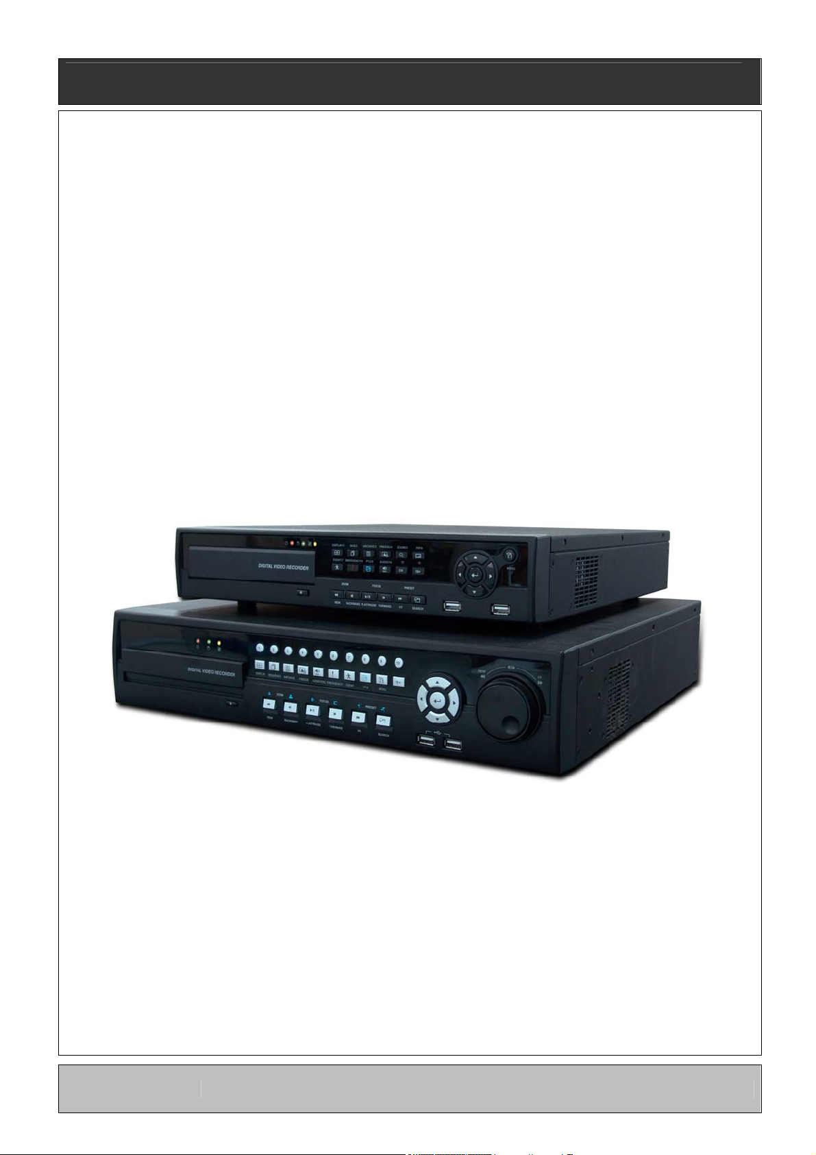
Standalone Digital Video Recorder
Premium DVR
4, 8, 16 Channel Models
User`s Manual
M4229KQCT
This document contains preliminary information and is subject to change without notice.
MADE IN KOREA
KQ3
FCC Compliance Statement
Notice to Users
: This equipment has been tested and found to comply with the limits for a Class A digital device. Pursuant to Part
15 of the FCC Rules, these limits are designed to provide reasonable protection against harmful interference when the
equipment is operated in a commercial environment. This equipment generates, uses and can radiate radio frequency energy
and, if not installed and used in accordance with the instruction manual, may cause harmful interference to radio
communications. Operation of this equipment in a residential area is likely to cause harmful interference in which case the user
will be required to correct the interference at own expense.
CAUTION
Changes or modifications not expressly approved by the party responsible for compliance could void the user’s authority to operate the
equipment.
The equipment complies with the requirement of FCC CFR 47 PART 15 SUBPART B, Class A.
Explanation of Graphical Symbols
This symbol indicates the presence of important operating and maintenance (servicing)
instruction in the literature accompanying the product.
This symbol indicates the presence of non-insulated “dangerous voltage” within the product’s
enclosure that may be of sufficient magnitude to constitute a risk of electric shock to
persons.
Warnings
Installation and servicing should be performed only by qualified and experienced personnel.
Power off the DVR when connecting cameras, audio, or sensor cables.
The manufacturer is not responsible for any damage caused by improper use of the product or failure to follow instructions for
the product.
The manufacturer is not responsible for any problems caused by or resulting from the user physically opening the DVR for
examination or attempting to fix the unit.
The manufacturer may not be held liable for any issues with the unit if any labels are removed in the product.
2

Cautions
This product has multiple-rated voltages (110V and 220V). See installation instructions before connecting to the power supply.
This product uses a Lithium battery.
To avoid any risk of explosion, do not replace the battery on the main board by anything other than a Lithium battery.
Dispose of used batteries according to the manufacturer’s instructions.
This equipment and all communication wirings are intended for indoor use only.
To reduce the risk of fire or electric shock, do not expose the unit to rain or moisture.
WEEE(Waste Electrical and Electronic Equipment)
Important Safeguards
1. Read Instructions
To reduce the risk of fire or electric shock, do not expose the unit to rain or moisture.
2. Retain Instructions
The safety and operating instructions should be retained for future reference.
3. Cleaning
Unplug this equipment from the wall outlet before cleaning it. Do not use liquid aerosol cleaners. Use a damp soft cloth for
cleaning.
4. Attachments
Never add any attachments and/or equipment without manufacturer approval as such additions may result in the risk of fire,
electric shock, or other personal injury.
5. Water and/or Moisture
Do not use this equipment near water or in contact with water.
6. Accessories
Do not place this equipment on an unstable cart, stand or table. The equipment may fall, causing serious injury to a child or
adult and serious damage to the equipment.
Wall or shelf mounting should follow the manufacturer’s instructions and should use a mounting kit approved by the
manufacturer.
Customers in European Union countries are advised to dispose this product, at the end of its
useful life, as per applicable local laws, regulations and procedures.
Move this equipment and cart combination with care. Quick stops, excessive force and uneven surfaces may cause the
equipment and cart combination to overturn.
7. Power Sources
This equipment should be operated only from the type of power source indicated on the marking label. If not sure the type of
power, please consult to distributor or local power company.
8. Power Cords
Operator or installer must remove power, BNC, alarm and other connections before moving the equipment.
9. Lightning
For added protection for this equipment during a lightning storm, or when it is left unattended and unused for long periods of
time, unplug it from the wall outlet and disconnect the antenna or cable system. This will prevent damage to the equipment
due to lightning and power-line surges.
10. Overloading
Do not overload wall outlets and extension cords to avoid the risk of fire or electric shock.
3

11. Objects and Liquids
Never push objects of any kind through openings of this equipment as they may touch dangerous voltage points or short out
parts that could result in a fire or electric shock.
Never spill liquid of any kind on the equipment.
12. Servicing
Do not attempt to service this equipment yourself. Refer all servicing to qualified service personnel.
13. Damage Requiring Service
Unplug this equipment from the wall outlet and refer servicing to qualified service personnel under the following conditions:
① When the power-supply cord or the plug has been damaged.
② If liquid is spilled or objects have fallen into the equipment.
③ If the equipment has been exposed to rain or water.
④ If the equipment does not operate normally by following the operating instructions, adjust only those controls that are
covered by the operating instructions as an improper adjustment of other controls may result in damage and will often
require extensive work by a qualified technician to restore the equipment to its normal operation.
⑤ If the equipment has been dropped or damaged the cabinet.
⑥ When the equipment exhibits a distinct change in performance—this indicates a need for service.
14. Replacement Parts
When replacement parts are required, ensure the service technician uses replacement parts specified by the manufacturer
or that have the same characteristics as the original part. Unauthorized substitutions may result in fire, electric shock, or
other hazards.
15. Safety Check
Upon completion of any service or repairs to this equipment, ask the service technician to perform safety checks to
determine that the equipment is in proper operating condition.
16. Field Installation
This installation should be made by a qualified service person and should conform to all local codes.
17. Correct Batteries
CAUTION
Changes or modifications not expressly approved by the party responsible for compliance could void the user’s authority to operate the
equipment.
18. Operating Temperature
An operating temperature range is specified so that the customer and installer may determine a suitable operating
environment for the equipment.
19. Elevated Operating Ambient Temperature
If installed in a closed or multi-unit rack assembly, the operating ambient temperature of the rack environment may be
greater than room ambient. Therefore, consideration should be given to installing the equipment in an environment
compatible with the specified operating temperature range.
20. Reduced Air Flow
Installation of the equipment in the rack should be such that the amount of airflow required for safe operation of the
equipment is not compromised.
21. Mechanical Loading
Mounting of the equipment in the rack should be such that a hazardous condition is not caused by uneven mechanical
loading.
22. Circuit Overloading
Consideration should be given to connection of the equipment to supply circuit and the effect that overloading of circuits
might have on over-current protection and supply wiring. Appropriate consideration of equipment nameplate ratings should
be used when addressing this concern.
23. Reliable (Grounding)
Reliable grounding of rack mounted equipment should be maintained. Particular attention should be given to supply
connections other than direct connections to the branch circuit (for example, use of power strips).
Warning
Warranty is void if seal or label is removed or damaged.
4
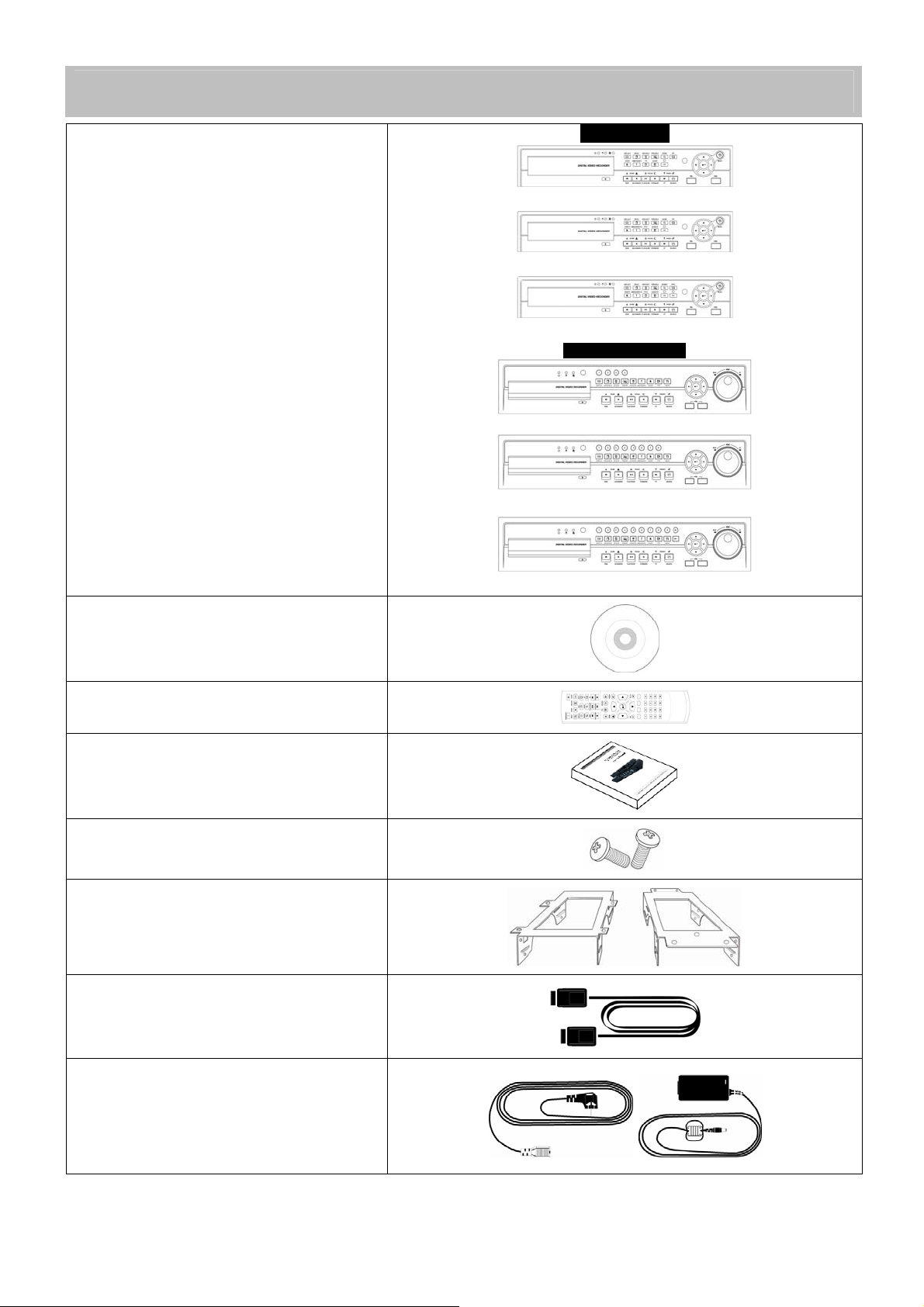
The List of Configuration
A and C Type
4CH
8CH
16CH
DVR Set
B, D, E and F Type
CD (CMS Software/Manual)
Remote Controller
Manual
Screws
4CH
8CH
16CH
HDD Brackets
Data Cable
Power Cable
(Except E and F Type Model)
5

Operation Precautions
Power Off
Do not turn DVR off, or plug off the power adapter while DVR is in operation (record/playback). Otherwise, it may cause
permanent damage to the equipment. Please click ( ) SETUP>SYSTEM>Shutdown sequentially and then remove the
power after DVR is shutdown completely. It is safe to wait for 5 seconds before turning the power on again.
Do not turn DVR off, or plug off the power adapter while External storage
external hard disk and the like) in use. Otherwise, it may cause permanent damage to the equipment. Make sure that the
power switch is in the “ON” position until data storage is completed. Please be aware that removing the storage device
cause the same damage to the equipment.
Do not turn DVR off, or plug off the power adapter during the format of the hard disk
damage to the equipment. Make sure that the power switch is in the “ON” position until the formatting of the disk is
completed.
HDD Installation / Addition / Moving / Replacement / Removal
For installation/addition/replacement/Removal of HDD (DVD-RW), make sure that DVR is turned off. Otherwise, it may
cause permanent damage to the HDD (DVD-RW).
When wish to power DVR off, please click ( ) SETUP>SYSTEM>Shutdown sequentially and then remove the power after
DVR is shut down completely.
Installation/Addition/Moving/Replacement: Start ‘HDD initialization’ including formatting. Otherwise, DVR would not
recognize the hard disk and may begin to function abnormally. Please follow the below procedure for ‘HDD initialization’.
① (Date/Time setup) Set up the current date and time (SETUP>SYSTEM>Admin>Date/Time).
② (Initialization of system setup) All setup values are restored to original factory default settings.
(SETUP>SYSTEM>Information>Status>Setup>Default).
③ (HDD format) HDD format is done by SETUP>SYSTEM>Admin>Storage>Format. If there are more than two HDDs,
each must be formatted, separately. When the format is completed, DVR will auto-reboot.
Removal: Follow the Remove procedure even when a pre-installed hard disk has been removed.
- SETUP>SYSTEM>Admin>Storage>Format, click ( ) ‘Removed’ item under the discrete Format headings of a
corresponding HDD to discard ‘HDD’ item. When the Remove procedure is completed, DVR will auto-reboot.
Date / Time Change
Any change in Date/Time is immediately applied onto live video (LIVE), but the date/time when the recording was done are
not changed.
Make sure to reboot DVR after adjusting the Date/Time.
Also, do not forget to execute SETUP>SYSTEM>Shutdown in sequence before reboot.
Upgrade
Do not upgrade until install a hard disk drive. Make sure that upgrade when the hard disk drive is in proper operation.
Using a Mouse
Left mouse button: have the same function as Enter ( ) on the Front panel of DVR.
Central button (wheel): have the same function as Search key on the Front panel of DVR(display search menu).
Right mouse button: display a number of ‘Function keys’ (please see ‘Input Device and Screen Icons>Using a mouse’ in
this manual).
PLAY / PAUSE Key
Press the PLAY/PAUSE key to one-touch playback on the viewing screen (playback the recorded video from the last one
minute).
Every time pressing the PLAY/PAUSE key during playback mode, it is changed to ‘1X PLAY’ and ‘PAUSE’. The displayed
sign on the screen also changes from
If wish to change mode (1X PLAY, REW, FF, BACKWARD, FORWARD) during playback, always press the PLAY/PAUSE
key first (please see if the sign II is shown on the screen).
Press the PLAY/PAUSE key to back up. Make sure that the backup is done in ‘PAUSE’ mode.
to II.
Camera Title
Camera Title displayed in Record and Playback modes of DVR is set to CAM1 ~CAM16. Registering camera title in setup
menu (DEVICES>Camera/PTZ>Title) is to make every setup process easier.
device (e.g., USB memory stick, removable
. Otherwise, it may cause permanent
6

Table of Contents
Server
1. PRODUCT FEATURES .............................................................9
4.4.4 Alarm In ....................................................................... 43
4.4.5 Alarm Out .................................................................... 44
4.4.6 Serial In ....................................................................... 44
1.1 Unpacking ..............................................................................9
1.2 Service ...................................................................................9
1.3 System Connection Diagram .................................................9
2.1 Hard disk and DVD-RW Installation .....................................15
2.1.1 SATA Port ....................................................................15
2.1.2 Internal SATA Storage (D, E and F Type) ...................15
2.1.3 e-SATA External Storage (D, E and F Type) ...............16
2.1.4 HDD Installation ...........................................................16
2.1.5 Maximum HDD Capacity..............................................16
2.1.6 DVD-RW installation ....................................................17
2.2 Connector Wiring .................................................................17
2.2.1 Video-In/Out Connections............................................17
2.2.2 Monitor Connections (Video Out, VGA and Spot)........17
2.2.3 HDMI connections (C, D, E and F Type) .....................17
2.2.4 Audio Connections.......................................................18
2.2.5 TCP/IP(Ethernet) Connections ....................................18
2.2.6 Alarm Connections.......................................................18
2.2.7 RS-485/422 Connections.............................................18
2.2.8 USB Connections.........................................................18
2.2.9 RS-232 Connections....................................................18
2.2.10 Factory Reset Switch ...................................................18
2.2.11 Power Supply connections...........................................18
2.2.12 Connections Guideline.................................................19
3. INPUT DEVICE AND SCREEN ICONS...................................20
3.1 Key and LEDs ......................................................................20
3.2 Camera Select Keys for 16 Channel DVR ...........................22
3.3 Front Panel...........................................................................22
3.4 Using a Remote Controller...................................................23
3.5 Using a Mouse .....................................................................23
3.6 Screen Icon ..........................................................................24
4.5 RECORD............................................................................. 44
4.5.1 Setting ......................................................................... 45
4.5.2 Schedule ..................................................................... 50
4.5.3 Pre Alarm .................................................................... 51
4.5.4 Motion Detection ......................................................... 52
4.5.5 Holiday ........................................................................ 53
4.6 LINK .................................................................................... 53
4.6.1 Alarm In ....................................................................... 53
4.6.2 Motion Event ............................................................... 54
4.6.3 Video Loss................................................................... 54
4.6.4 System Event .............................................................. 55
4.6.5 Popup Link .................................................................. 55
5. OPERATION INSTRUCTION ................................................. 57
5.1 Viewing................................................................................ 57
5.1.1 First Image .................................................................. 57
5.1.2 View Format ................................................................ 57
5.1.3 Digital Zoom ................................................................ 58
5.1.4 Freeze Live Image....................................................... 58
5.1.5 Pan / Tilt Control.......................................................... 58
5.1.6 System Log ................................................................. 59
5.1.7 Key Lock...................................................................... 60
5.1.8 Emergency Recording................................................. 60
5.2 Search ................................................................................. 60
5.2.1 Date / Time Search ..................................................... 60
5.2.2 Calendar Search ......................................................... 61
5.2.3 Event Search............................................................... 61
5.3 Playback.............................................................................. 62
5.4 One-touch Playback ............................................................ 63
5.5 Digital Zoom in Playback..................................................... 63
5.6 Archive ................................................................................ 64
5.7 Menu Bar............................................................................. 65
5.8 Color Control and Position .................................................. 66
4. SETUP .....................................................................................25
4.1 Login / Logout ......................................................................25
4.2 SYSTEM ..............................................................................26
4.2.1 Information ...................................................................26
4.2.2 Admin...........................................................................28
4.2.3 Account ........................................................................32
4.2.4 System Log ..................................................................34
4.2.5 Exit ...............................................................................34
4.2.6 Shutdown .....................................................................35
4.3 DISPLAY ..............................................................................35
4.3.1 OSD .............................................................................35
4.3.2 Main Monitor ................................................................36
4.3.3 Spot Monitor.................................................................36
4.3.4 Spot Monitor Control on Display Mode ........................37
4.3.5 Multi Spot (C and D Type) ...........................................37
4.3.6 VGA .............................................................................38
4.4 DEVICES .............................................................................39
4.4.1 Network........................................................................39
4.4.2 Camera / PTZ ..............................................................42
4.4.3 Audio............................................................................43
5.9 Alarm Out Control................................................................ 66
CMS
6. PROGRAM INSTALLATIONS ................................................ 68
6.1 System Recommendations ................................................. 68
6.2 Program Installation Method ............................................... 68
6.3 Login.................................................................................... 69
7. FUNCTION AND INSTRUCTIONS ......................................... 70
8. WATCH MODE ....................................................................... 71
8.1 LOGIN Screen..................................................................... 71
8.2 Local Setting........................................................................ 71
8.2.1 System Setup .............................................................. 71
7

8.2.2 Remote Site .................................................................72
8.3 Live Video ............................................................................74
8.3.1 Network Connection.....................................................74
8.3.2 Watch Mode.................................................................75
8.3.3 Multi Screen .................................................................76
8.3.4 Screen Color Adjustment .............................................76
8.3.5 Audio............................................................................77
8.3.6 System Log ..................................................................77
8.3.7 Alarm Out.....................................................................77
8.3.8 One touch Recording ...................................................77
8.4 PTZ Control..........................................................................77
8.5 Health Check........................................................................79
8.5.1 Camera connections and Operating Status .................79
8.5.2 HDD connections and Operating Status ......................79
8.5.3 Recording Status .........................................................80
8.5.4 Motion Recording Status..............................................80
8.5.5 Alarm In Connection and Operating Status .................80
8.5.6 Alarm Out Connection and Operating Status...............80
8.6 Remote Setting ....................................................................80
9. SEARCH MODE ......................................................................82
9.1 Search Screen .....................................................................82
9.2 Remote Search ....................................................................83
9.3 Local Search ........................................................................83
12.2.2 Installation ................................................................. 102
12.2.3 Site Registration ........................................................ 103
12.2.4 Connection ................................................................ 104
12.2.5 PTZ Control ............................................................... 104
12.2.6 Disconnection............................................................ 105
12.2.7 Uninstall..................................................................... 105
12.3 Blackberry Mobile.......................................................... 106
12.3.1 System Requirements ............................................... 106
12.3.2 Installation ................................................................. 106
12.3.3 Site Registration ........................................................ 107
12.3.4 Connection ................................................................ 107
12.3.5 PTZ Control ............................................................... 108
12.3.6 Disconnection............................................................ 109
12.3.7 Uninstall..................................................................... 109
12.4 Windows Mobile ............................................................ 109
12.4.1 System Requirements ............................................... 109
12.4.2 Installation ................................................................. 109
12.4.3 Site Configuration...................................................... 112
12.4.4 Connection ................................................................ 113
12.4.5 Uninstall..................................................................... 114
Application
13. KEYBOARD CONTROLLER ................................................ 116
13.1 Connection .................................................................... 116
13.1.1 Configuration Diagram I ............................................ 116
13.1.2 Configuration Diagram II ........................................... 116
13.1.3 Configuration Diagram III .......................................... 117
9.4 Event Search........................................................................84
9.5 Playback...............................................................................84
9.5.1 Playback Control Button ..............................................84
9.5.2 Print..............................................................................85
9.5.3 Save.............................................................................85
9.5.4 Archive .........................................................................85
10. OTHERS ..................................................................................87
10.1 Viewer ..............................................................................87
10.2 E-MAP..............................................................................87
10.3 Watermark Check System ...............................................89
10.4 Estimator..........................................................................89
10.5 EXE to AVI Converter ......................................................89
11. CMS WEB CLIENT..................................................................92
11.1 Setup and Login...............................................................92
11.2 Live Display......................................................................93
11.3 Playback Screen ..............................................................94
12. CMS MOBILE VIEWER ...........................................................96
12.1 iPhone Mobile ..................................................................96
12.1.1 System Requirements..................................................96
12.1.2 Installation....................................................................96
12.1.3 Site Registration...........................................................98
12.1.4 Connection...................................................................99
12.1.5 PTZ Control..................................................................99
12.1.6 Disconnection ............................................................100
12.1.7 Uninstall .....................................................................101
12.2 Android Phone ...............................................................102
12.2.1 System Requirements................................................102
8
13.2 Keyboard Setup in DVR ................................................ 117
13.3 Keyboard Configuration................................................. 118
13.4 Operation....................................................................... 118
13.4.1 DVR/PTZ Mode conversion....................................... 118
13.4.2 DVR Control Mode .................................................... 118
13.4.3 PTZ Control Mode ..................................................... 119
14. SERIAL IN (POS/ATM) ......................................................... 121
14.1 Usage of Serial-In Function........................................... 121
14.2 Connection Method ....................................................... 121
14.3 Connection Diagram...................................................... 121
14.4 Link................................................................................ 122
14.4.1 Link Setup ................................................................. 122
14.4.2 Schedule Setup ......................................................... 123
14.5 Setup ............................................................................. 123
14.5.1 Title............................................................................ 124
14.5.2 Port Setting................................................................ 124
14.5.3 OSD Display.............................................................. 124
14.5.4 Pattern Setting........................................................... 125
14.6 Search ........................................................................... 127
1. Product Features
1.1 Unpacking
This equipment is an electronic appliance, so it should be handled with special care.
After unpacking, please check if all the following items are included.
- DVR Main body
- A , B and C Type : Power Supply Adapter (DC 12V, 5A) and Power Supply Cable
- D Type : Power Supply Adapter (DC 12V, 6.67A) and Power Supply Cable
- E and F Type : Power Supply Cable
- Remote Control With 2 AAA batteries
- Installation CD (CMS Software & User’s Manual)
1.2 Service
If there is any problem in the product, please refer servicing to a supplier or a distributor with qualified service personnel.
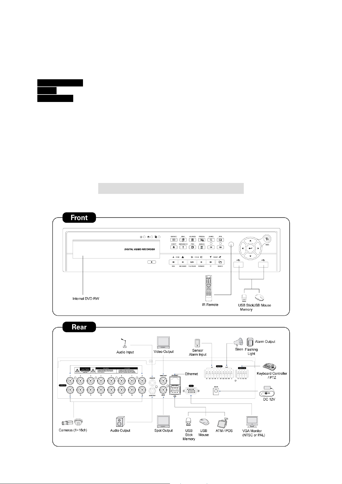
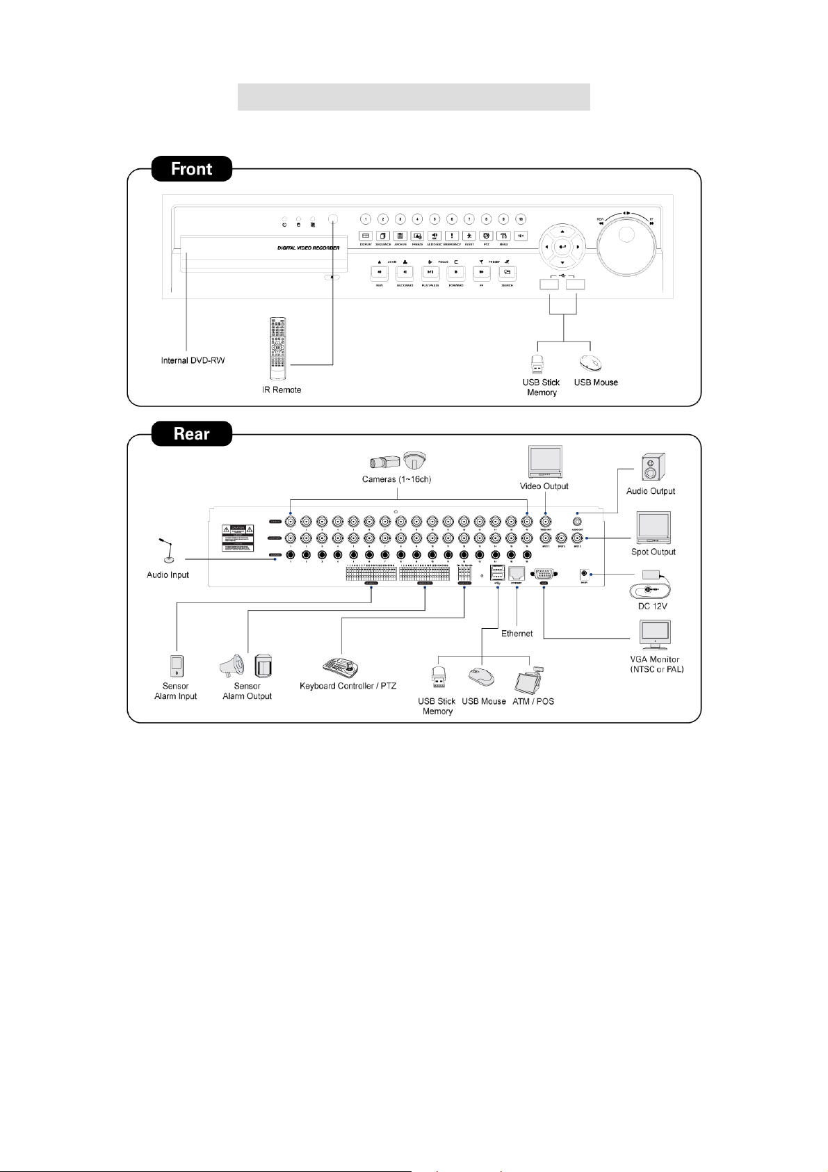
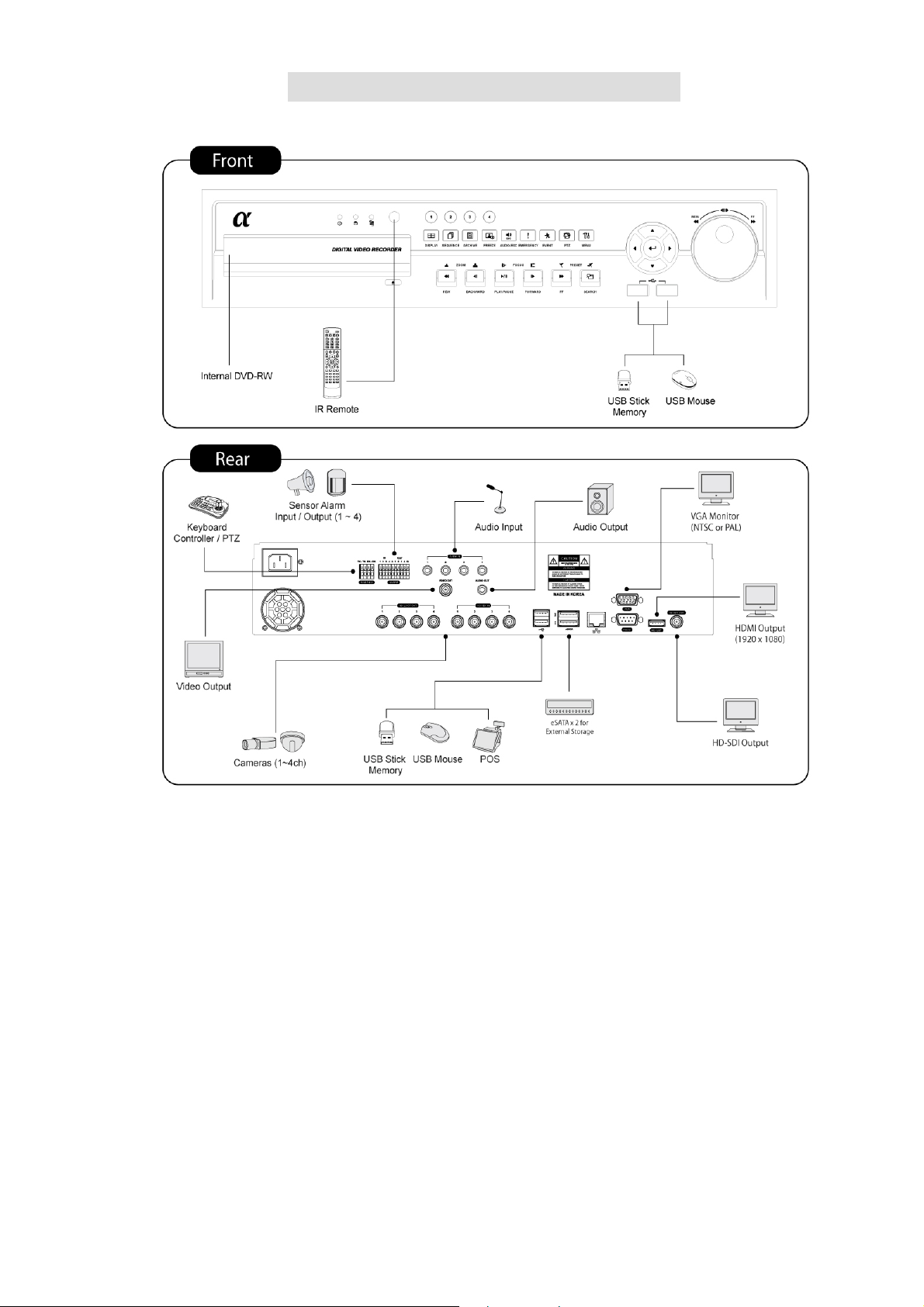
1.3 System Connection Diagram
A Type –4 / 8 / 16 channel Series DVR
9
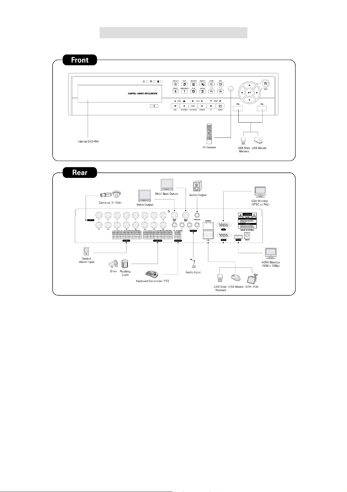
B Type –4 / 8 / 16 channel Series DVR
10
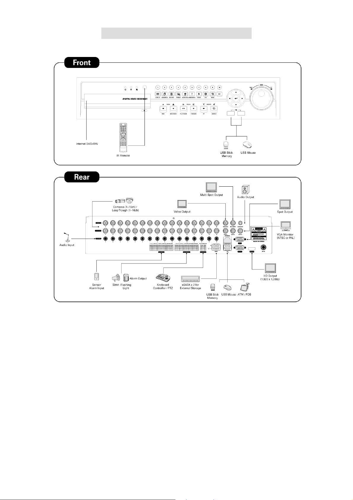
C Type –4 / 8 / 16 channel Series DVR
11
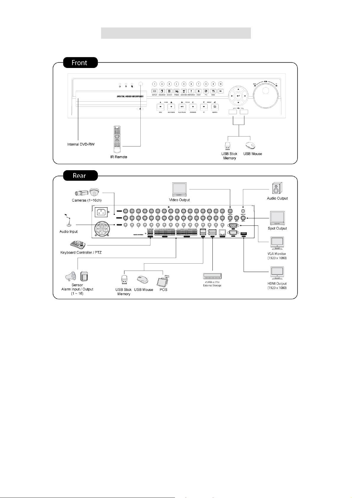
D Type–4 / 8 / 16 channel Series DVR
12
E Type –8 / 16 channel Series DVR
13
F Type –4 channel Series HD-SDI DVR
14

2. Installation
2.1 Hard disk and DVD-RW Installation
2.1.1 SATA Port
A and C Type
- Main substrate of this DVR has three SATA ports: they are indicated as SATA 1, 2 and SATA 3.
- Please mount DVD-RW at the SATA 3 port.
B Type
- Main substrate of this DVR has four SATA ports: they are indicated as SATA 1, 2, 3 and SATA 4.
- Please mount DVD-RW at the SATA 4 port.
D, E and F Type
- Main substrate of this DVR has five SATA ports: they are indicated as SATA 1, 2, 3, 4 and SATA 5.
- Please mount DVD-RW at the SATA 4 port.
Up to five SATA devices (hard disk and DVD-RW) are able to be connected to the SATA ports in serial, however the devices
must be connected onto correct SATA port.
Refer to below table to mount a hard disk and DVD-RW.
A and C Type
Storage SATA 1, 2 Port SATA 3 Port
4 / 8 / 16 CH DVR
B Type
HDD DVD-RW 1 2 3
1 1 HDD --- DVD-RW
2 1 HDD HDD DVD-RW
Storage SATA 1, 2 Port SATA 3, 4 Port
HDD DVD-RW 1 2 3 4
4 / 8 / 16 CH DVR
1 1 HDD --- --- DVD-RW
2 1 HDD HDD --- DVD-RW
3 1 HDD HDD HDD DVD-RW
3 0 HDD HDD HDD ---
D, E and F Type
Storage SATA 1, 2 Port SATA 3, 4 Port
HDD DVD-RW 1 2 3 4 5
1 1 HDD --- --- DVD-RW ---
4 / 8 / 16 CH DVR
2 1 HDD HDD --- DVD-RW ---
3 1 HDD HDD HDD DVD-RW ---
4 1 HDD HDD HDD DVD-RW HDD
4 0 HDD HDD HDD --- HDD
2.1.2 Internal SATA Storage (D, E and F Type)
SATA 5
Port
These series DVRs have 5 Internal SATA Ports: The picture below shows internal ports 1-4 SATA Port and 5 SATA Port.
1-3 SATA Port: It is designed to mount HDD.
4 SATA Port: Please mount DVD-RW.
5 SATA Port: It is specifically designed to mount HDD ONLY.
15
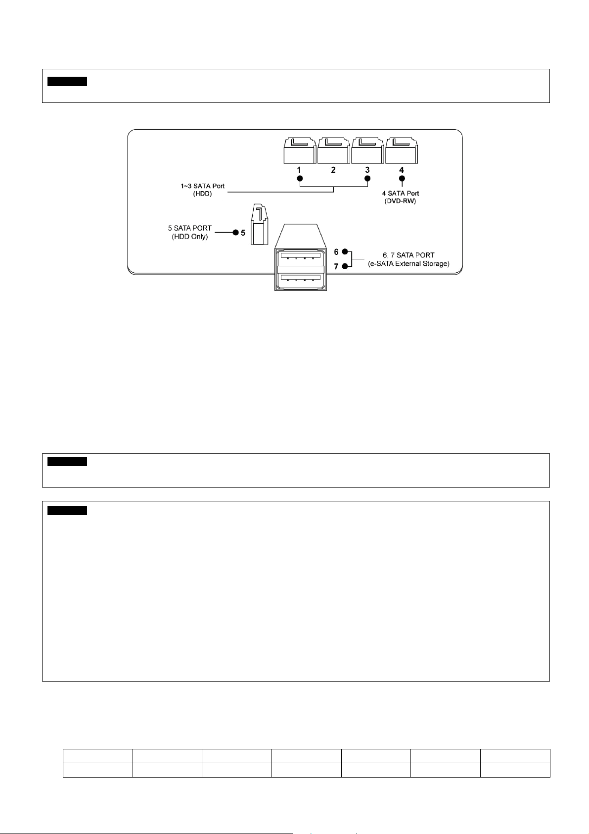
Only one DVD-RW can be installed among the SATA Ports.
CAUTION
Do not mount DVD-RW at SATA 5 Port.
2.1.3 e-SATA External Storage (D, E and F Type)
This series DVR has 2 external SATA Ports; the picture above shows external SATA 6-7 Port.
6-7 SATA Port: It is designed to mount 4HDDs per each external SATA Ports.
2.1.4 HDD Installation
Securely fix a hard disk by using bracket and screws provided herewith.
Please do not use any different hard disk cables (data cable and power supply cable) other than ones we provide.
Otherwise, it may cause damage to the hard disk.
CAUTION
Install hard disk after DVR power is off. Otherwise, it may cause permanent damage to the hard disk. To turn off DVR, please click ( )
SETUP>SYSTEM>Shutdown. Also, wait for 5 seconds before plugging in power supply again.
CAUTION
For installation/addition/replacement/Removal of HDD (DVD-RW), make sure that DVR is turned off. Otherwise, it may cause permanent
damage to the HDD (DVD-RW).
Installation/Addition/Moving/Replacement: User should start ‘HDD initialization’ including formatting. Otherwise, DVR won’t recognize
the hard disk and may begin to function abnormally. Please follow the below procedure for ‘HDD initialization’.
(Date/Time setup) Set up the current date and time (SETUP>SYSTEM>Admin>Date/Time)
①
(Initialization of system setup) All values in setup are restored to factory default settings
②
-
(SETUP>SYSTEM>Information>Status>Setup>Default)
③
(HDD format) HDD format is done by SETUP>SYSTEM>Admin>Storage>Format. If there are more than two HDDs, each must be
formatted, separately. When the format is completed, DVR will auto-reboot.
Removal: Follow the Remove procedure even when a pre-installed hard disk has been removed. In
-
SETUP>SYSTEM>Admin>Storage>Format, click ( ) ‘Removed’ item under the discrete Format headings of a corresponding HDD to
discard ‘HDD’ item. When the Remove procedure is completed, DVR will auto-reboot.
2.1.5 Maximum HDD Capacity
Each model has a different HDD capacity recognition.
Below table shows the recommended maximum HDD capacity for each model.
Model A type B type C type D type E type F Type
Capacity 4TB 6TB 4TB 16TB 16TB 16TB
16
2.1.6 DVD-RW installation
Securely fix DVD-RW by using bracket and screws provided herewith.
Please do not use any different DVD-RW cables (data cable and power supply cable) other than the ones we provide.
Otherwise, it may cause damage to the DVD-RW.
Only one DVD-RW can be used. Mount it at the SATA 3 port. (A and C Type) or SATA 4 port (B, D, E and F Type).
CAUTION
Install DVD-RW hard disk after DVR power off. Otherwise, it may cause permanent damage to the hard disk. To turn off DVR, please click ( )
SETUP>SYSTEM>Shutdown. Also, wait for 5 seconds before plugging in power supply again.
2.2 Connector Wiring
2.2.1 Video-In/Out Connections
Connect a camera to ‘VIDEO IN’.
If user wishes to link camera input to another device, please connect the camera to ‘LOOP OUT’.
Assure the ‘VIDEO IN’ and ‘LOOP OUT’ connections are connected properly, not oppositely.
(NOTE)
Only B, D and E Type model support LOOP OUT connection and F Type supports HD-SDI LOOP OUT connection.
2.2.2 Monitor Connections (Video Out, VGA and Spot)
Use with CCTV monitor and computer monitor. Please connect the CCTV monitor to ‘VIDEO OUT’, the computer monitor to
‘VGA’, respectively. If necessary, connect another CCTV monitor to ‘SPOT’ or ‘MULTI SPOT’.
Multi Spot (C and D Type)
- This function supports Multi Channel Display on Spot Monitor
- Connect BNC cable between spot monitor and multi spot port of rear panel.
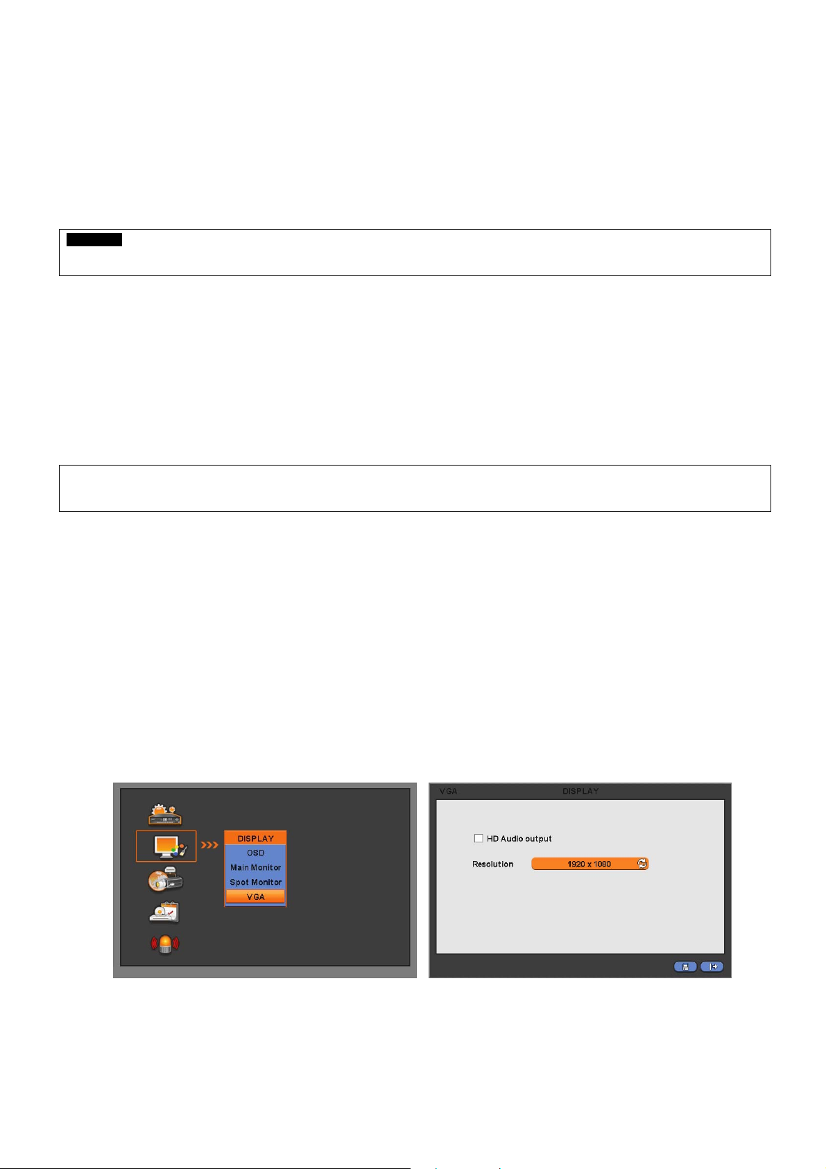
2.2.3 HDMI connections (C, D, E and F Type)
Connect HDMI cable to HD out port of rear panel and HDMI port of HD output device.
Please click ( ) SETUP> DISPLAY> VGA and the following screen will appear.
If user wishes to hear audio via HDMI cable, check the box HD Audio Output
Click the box below to select resolution.
- User can select the resolution among ‘1920x1080 RB’, ‘1920x1080’, ‘1680x1050 RB’, ‘1680x1050’, ‘1280x1024’, and
‘1024x768’
- The default setting of DVR is ‘1280 x 1024’.
17

(NOTE)
Only C and D Type supports
E and F Type do not have Multi Spot. But Support HDMI
HDMI connect and Multi Spot.
2.2.4 Audio Connections
Connect an audio device to ‘AUDIO IN’ and a speaker system to ‘AUDIO OUT’. Please use a speaker system with volume
adjustable.
2.2.5 TCP/IP(Ethernet) Connections
Connect to ‘ETHERNET’ connector with the LAN cable.
When connect to Internet, use an ordinary LAN cable (Non-cross cable). However, when connect directly to a PC, please
use only ‘Crossover cable’.
2.2.6 Alarm Connections
Connect Alarm Input (Sensor) to ‘AI 1~AI 4 (AI 16)’ connectors and connect Sensor Common to ‘G’ connector.
Connect Alarm Output (buzzer, siren, etc.) to ‘AO 1~AO 4 (AO 16)’ connectors and connect Common to ‘G’ connector.
Connect Pan/Tilt receiver (or Pan/Tilt camera) to ‘RS-485/422’ connector. Please observe proper (+) and (-) polarity.
2.2.7 RS-485/422 Connections
PTZ Camera connector.
Please use TX+, TX-, RX+ and RX- terminals.
2.2.8 USB Connections
There are four identical USB ports in front and in rear. It is possible to connect a USB memory stick to archive data or a
mouse to control the device.
2.2.9 RS-232 Connections
This port is not in use for users. Do not connect any devices through this port.
2.2.10 Factory Reset Switch
Reset the switch to restore all setup values of menus to factory default settings. It is also possible to use to initialize System
Log file.
The switch is located in a pin hole of the back panel.
Put the clip pin into the switch hole on the monitor (Live) screen and keep pressing until the switch has clicked.
CAUTION
Press factory reset switch only in live mode. Never press in setup mode.
2.2.11 Power Supply connections
A, B and C Type : Plug the power supply adapter (DC 12V, 5A) which include in this product to ’DC12V’ connector and
plug another side to power source. Adapter input voltage is a free volt (100 VAC ~ 240 VAC). Please do not use any
different power supply adapter because it may cause the DVR to malfunction.
D Type : Plug the power supply adapter (DC 12V, 6.67A) which include in this product to ’DC12V’ connector and plug
another side to power source. Adapter input voltage is a free volt (100 VAC ~ 240 VAC). Please do not use any different
power supply adapter because it may cause the DVR to malfunction.
E and F Type : AC powered DVR: Plug the power supply cable into the power supply (the wall socket). Input voltage is a
free volt (100 VAC ~ 240 VAC).
18

2.2.12 Connections Guideline
Video Out Connector: If only the monitor is connected to VIDEO OUT connector, please set the impedance switch on the
rear side of the monitor to 75 ohms to prevent abnormally bright or collapsed images. If wish to connect another device (e.g.,
a recorder) to the back of the monitor, please set the impedance switch on the rear side of the monitor to HIGH Z (High
Impedance) and set the last device to 75 ohms.
Alarm Input Connector: Do not input any type of voltage to the AI 1~AI 4 (AI 16) connectors.
19
3. Input Device and Screen Icons
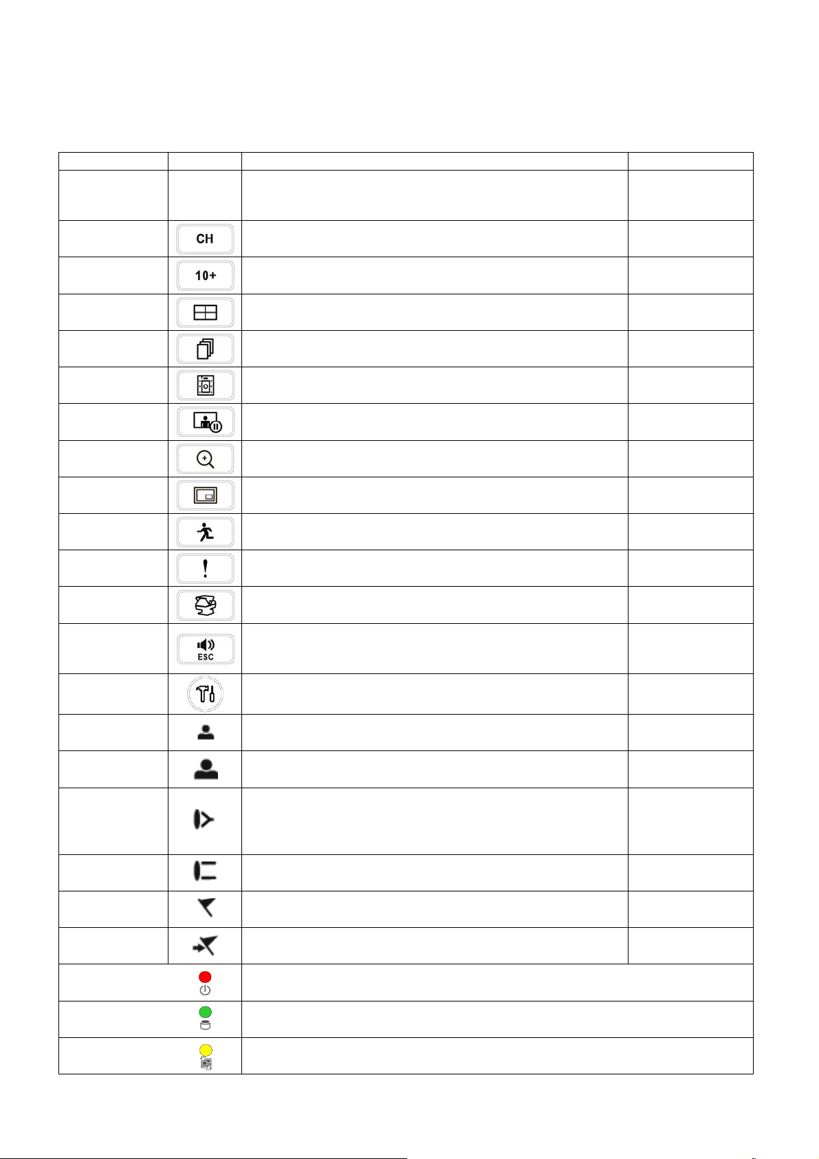
3.1 Key and LEDs
A and C Type
KEYS PTZ KEY Operating mode Setup mode
•Up/Down/Left/Righ
▲, ▼, ◄, ►
• Control Pan/Tilt rotation of up/down/left/right in PTZ mode
t on screen cursor
control
1 ~ 10
11 ~ 16
DISPLAY
SEQUENCE
ARCHIVE
FREEZE
ZOOM
PIP
EVENT
EMERGENCY
PTZ
AUDIO/ESC
• Camera select keys : (4/8 channel DVR)
• Camera select keys : (16 channel DVR)
• Select 1/4/9/16 channel display
• Channel sequence mode on/off (Main Monitor)
• Copy video data into the external storage device
• Screen freeze mode on/off
• Zoom-In/Out
• Picture In Picture display on/off
• System Log display on/off
• Emergency recording on/off
• Pan/Tilt control mode on/off
• Audio on/off (Viewing/Playback)
• Select audio channel: Press AUDIO key and then channel key
• ESC
MENU
REW
BACKWARD
PLAY/PAUSE
FORWARD
FF
SEARCH
Power LED
(Red)
HDD LED
(Green)
Network LED
(Yellow)
• Enter the Main Menu (Setup mode)
• Fast backward playback (changes up to x128 with each press)
• Zoom-Out on PTZ mode
• Frame backward playback
• Zoom-In on PTZ mode
• Viewing mode: Instant playback (playback the recorded video
from the last one minute)
• Playback mode: 1X PLAY/PAUSE
• Focus Near in PTZ mode
• Frame forward playback
• Focus Far in PTZ mode
• Fast forward playback (changes up to x128 with each press)
• Save Preset in PTZ mode
• Video search mode on/off
• Go to Preset in PTZ mode
• Light off: DVR off
• Light on: DVR on
• Light off: Stop recording
• Blink : Recording/Playback modes (HDD Access), Archive in operation
• Light off: failed to connect to Ethernet
• Blink: Connected to Ethernet
20
B, D, E and F Type
KEYS PTZ KEY Operating mode Setup mode
•Up/Down/Left/Righ
▲, ▼, ◄, ►
• Control Pan/Tilt rotation of up/down/left/right in PTZ mode
t on screen cursor
control
1 ~ 16
DISPLAY
SEQUENCE
ARCHIVE
FREEZE
EVENT
EMERGENCY
PTZ
AUDIO/ESC
• Camera select keys : (4/8/16 channel DVR)
• Select 1/4/9/16 channel display
• Channel sequence mode on/off (Main Monitor)
• Copy video data into the external storage device
• Screen freeze mode on/off
• System Log display on/off
• Emergency recording on/off
• Pan/Tilt control mode on/off
• Audio on/off (Viewing/Playback)
• Select audio channel: Press AUDIO key and then channel key
• ESC
MENU
REW
BACKWARD
PLAY/PAUSE
FORWARD
FF
SEARCH
Power LED
(Red)
HDD LED
(Green)
Network LED
(Yellow)
• Enter the Main Menu (Setup mode)
• Fast backward playback (changes up to x128 with each press)
• Zoom-Out on PTZ mode
• Frame backward playback
• Zoom-In on PTZ mode
• Viewing mode: Instant playback (playback the recorded video
from the last one minute)
• Playback mode: 1X PLAY/PAUSE
• Focus Near in PTZ mode
• Frame forward playback
• Focus Far in PTZ mode
• Fast forward playback (changes up to x128 with each press)
• Save Preset in PTZ mode
• Video search mode on/off
• Go to Preset in PTZ mode
• Light off: DVR off
• Light on: DVR on
• Light off: Stop recording
• Blink : Recording/Playback modes (HDD Access), Archive in operation
• Light off: failed to connect to Ethernet
• Blink: Connected to Ethernet
21
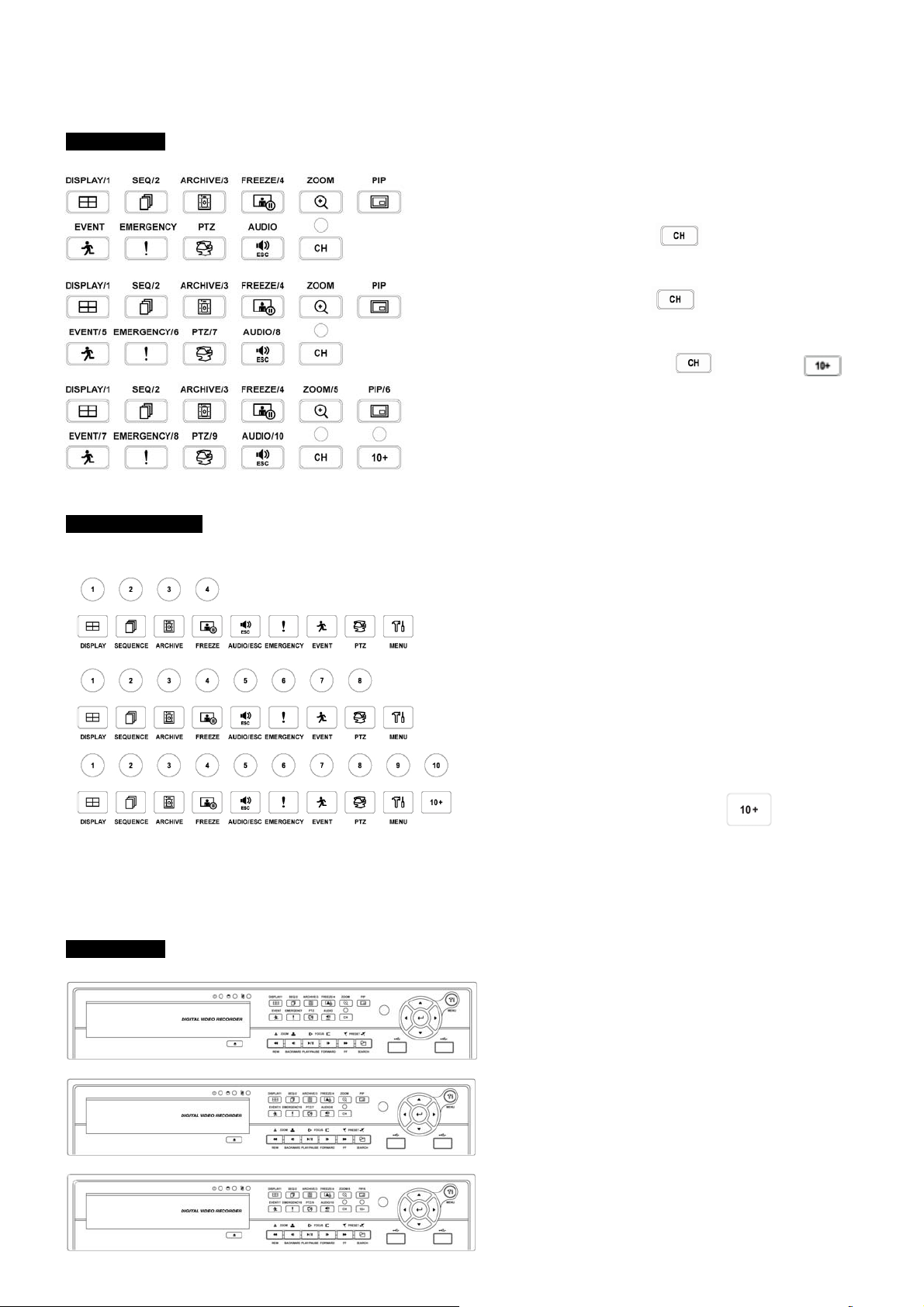
3.2 Camera Select Keys for 16 Channel DVR
A and C Type
Below shows how to select camera channel for 4 channel DVR
B, D, E and F Type
- Select Camera No. 1~4: press
Below shows how to select camera channel for 8channel DVR
- Select Camera No. 1~8 press
Below shows how to select camera channel for 16hannel DVR
- Select Camera No. 10~16: press
1~6 key
Below shows how to select camera channel for
4/8/16channel DVR
Below shows how to select camera channel for 4 channel
DVR
- Select Camera No. 1~4
Below shows how to select camera channel for 8 channel
DVR
- Select Camera No. 1~8
Below shows how to select camera channel for 16
channel DVR
- Select Camera No. 1~10: use 1~10 direction key
key and use 1~4 key
key and use 1~8key
key and use ,
3.3 Front Panel
A and C Type
- Select Camera No. 11~16: press
1~6 direction key
4 Channel DVR
8 Channel DVR
16 Channel DVR
22
key and use
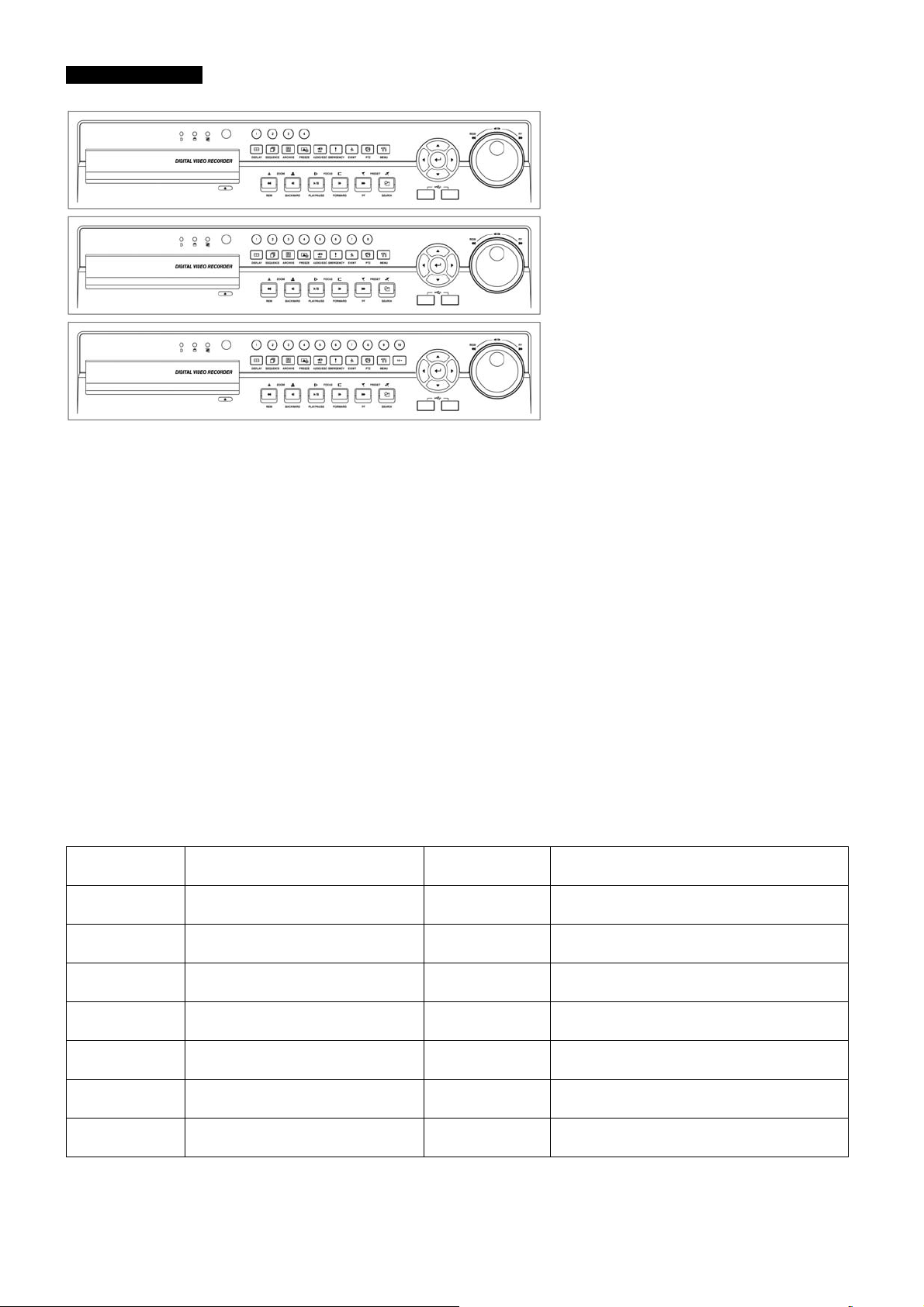
B, D, E and F Type
4 Channel DVR
8 Channel DVR
16 Channel DVR
3.4 Using a Remote Controller
Usage of a remote controller is same as the front panel keys.
Follow the procedure below when using the remote controller for multi DVRs.
① Check System ID (e.g., between 1 and 255) of the DVR that wish to use.
- (SETUP>SYSTEM>Information>Status>System ID).
② Holding up the remote controller to face towards the DVR and press the System ID numbers one by one, while pressing
ID button on the remote controller. Note that the System ID is a 3-digit number. Button ‘10’ functions the same as ‘0’.
- (e.g.: If System ID is 3, press 10>10>3 buttons in sequence while pressing the ID button)
3.5 Using a Mouse
Mouse provides an easier access to adjustment. Refer to below for proper use.
Left mouse button functions the same as Enter ( ) key on the front panel of DVR.
Right mouse button displays the following “Function keys” on screen.
Click Search menu at “Function Keys” the same as Search key on the front panel of DVR. Press the button, then the Search
menu will appear on screen.
Name of Key
Display Same as front key Event
Sequence
Spot Same as front key Setup
Zoom Same as front key Emergency
Freeze
PIP Same as front key Cancel
PTZ
Same as front key
Same as front key
Same as front key
Function
Name of Key Function
Same as front key (indicate System Log)
Search
Shutdown
One-touch playback (same function with
(PLAY/PAUSE)
Same as front key
Same as front key
Pre-step before Power off
(SETUP>SYSTEM>Shutdown)
Cancel Function key menu
23

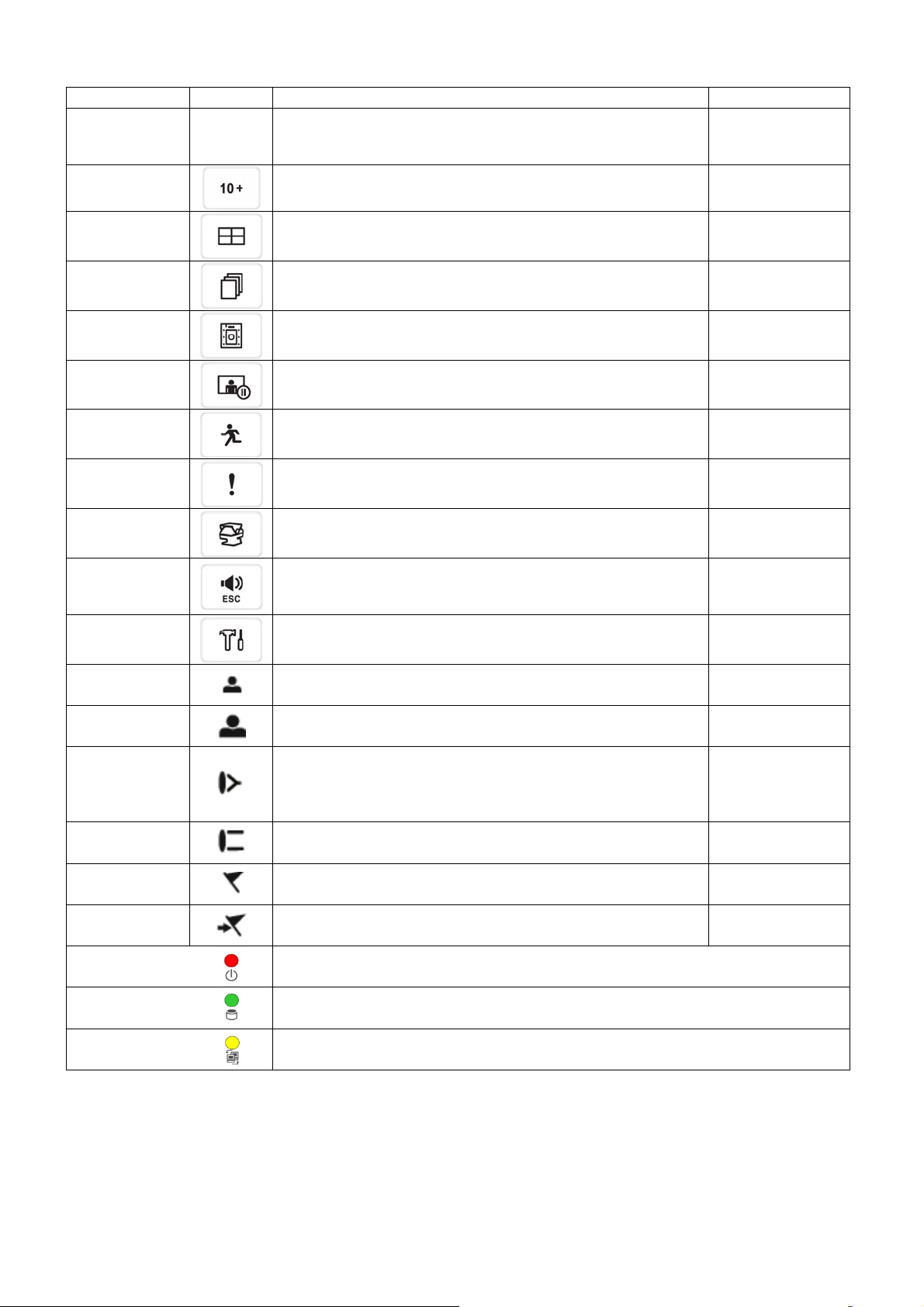
3.6 Screen Icon
Icon Description Icon Description
Continuous recording mode
Event recording mode
(Alarm In/Motion)
In recording
PTZ registration / PTZ mode
Remote Controller
Setup in HDD No Overwrite mode
(HDD Full)
In Audio recording
CMS access indication/ No. of accesses
4
(up to 4)
In channel sequencing
Lock
Setup in HDD Overwrite mode
Setup in HDD No Overwrite mode
(recording)
24
4. Setup
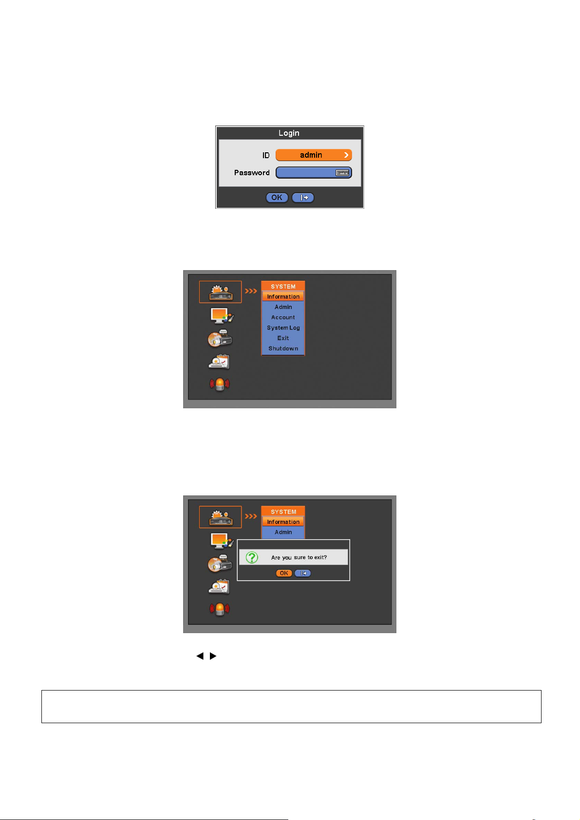
4.1 Login / Logout
At the default setting of DVR, user has to input the password to enter the set up menu.
Please press SETUP key to enter the setup menu and the following screen will appear.
In order to use all functions and privileges, login is as ID: admin.
Default Password is “1111”.
At Setup>System>Account, Administrator should set an user rights depending on each users separately in “Login Settings”.
After login successfully, following screen will appear:
Recording continues during setup.
Main menu consists of 5 sub menus.
- (SYSTEM / DISPLAY / DEVICES / RECORD / LINK)
There is no factory default in the case of passwords.
To escape from the setup menu, please click ( ) on SYSTEM>Exit on the screen. Then, the following dialogue box will
appear.
Please choose ‘OK’ to log out.
User may select the Main menu with
submenu under the Main menu.
(NOTE)
Press AUDIO/ESC in the setup screen, start operation alike CANCEL (ESC).
It will not operate live or playback mode but only in the setup menu.
, direction keys or mouse click. Please click ( ) the submenu to choose a
25
4.2 SYSTEM
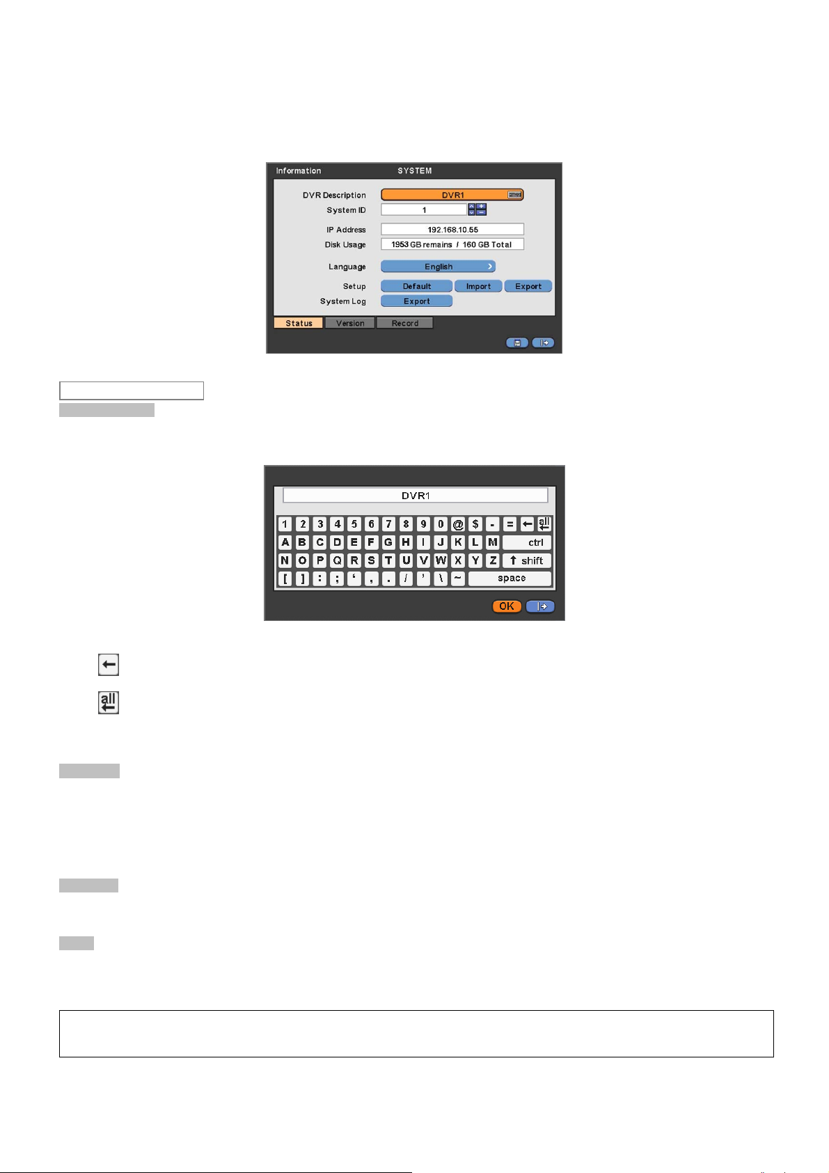
4.2.1 Information
Please click ( ) SYSTEM>Information and the following screen will appear.
Status
Site Description
Decide name of DVR.
Please click ( ) keyboard icon on Site Description frame and the following virtual keyboard will appear.
Please click ( ) desired letters (characters) on the virtual keyboard to input.
① Use to erase one character every time.
Use to erase the whole sentence.
②
Please choose ‘OK’ to confirm the input and choose ‘Cancel’ to cancel.
System ID
Control DVRs by one remote controller by setting DVR IDs.
Please click ( ) ▲, ▼ direction keys on the right-hand side of the System ID frame to set the ID of DVR. Take any whole
number between 1 and 255.
While pressing (+) or (-) button, the System ID value increases or decreases by 10 units.
Language
Please click ( ) Language frame to choose desired language and press ( ) key again.
Setup
Default: Click ( ) Default frame to restore all setup values of menus to factory default settings. Please note that System Log
is not initialized.
(NOTE)
This has a different function from Factory Reset Switch on the back panel of DVR in that System Log is not initialized.
26

Import: Copy the Menu setup stored in USB memory stick into DVR. Please plug in the memory stick and then click ( )
Import.
Export: Store the Menu setup of DVR in USB memory stick. Please plug in the memory stick and then click ( ) Export.
When user is on Default, Import or Export process, a message box will ask the progress and click the confirmation icon, then
a message box will show whether its success or failure.
System Log
Export: Store the System Log contents in USB memory stick. Please plug in the memory stick and then click ( ) Export.
When user is on Default, Import or Export process, a message box will ask the progress and click the confirmation icon, then
a message box will show its success or failure.
Version
When user complete Status data input, please click ( ) Version and the following screen will appear.
Version Upgrade
User may upgrade DVR software.
Please follow the Upgrade procedure below.
① Plug USB memory stick having upgrade file into DVR.
② Click ( ) Load frame. Then, software version stored in the USB will appear on the left-hand side.
③ Click ( ) Start frame to start the upgrade.
④ When the upgrade is completed, a dialogue box pops up. Please choose ‘OK’ and DVR will auto-reboot.
CAUTION
DO NOT UPGRADE UNTIL INSTALL A HARD DISK DRIVE. MAKE SURE TO UPGRADE WHEN HDD IS IN PROPER OPERATION.
CAUTION
PLUGGING OUT USB DEVICE OR FORCED POWER-OFF MAY CAUSE PERMANENT DAMAGE.
Record
When user completes Version input, please click ( ) Record. Then, the following screen will appear.
The screen shows start time and end time of recorded data.
Overwrite Setting
Click ( ) Overwrite Setting button and the following screen will appear.
27
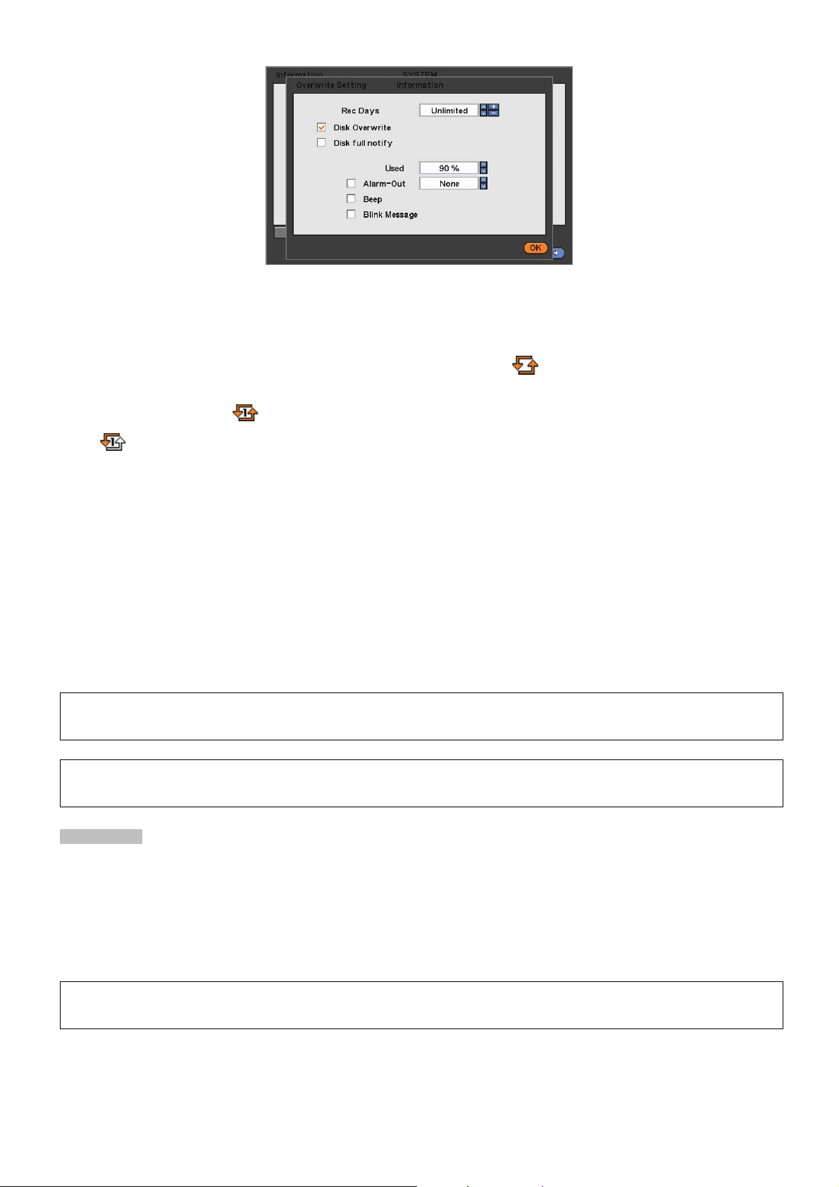
User shall designate the total recording days from 1 day to 30 days and unlimited.
User may set for beeping or notifying messages that notify the used percentage of disk.
Check Disk Overwrite and user may activate the overwrite function.
- This function makes restart the recording from the beginning when the HDD is full. The previous recorded data will be
erased from the first one. Following icon will display in bottom of live mode.
① Uncheck (□) Disk Overwrite, recording will stop automatically when the HDD is full.
② At no Overwrite mode,
icon will appear when HDD capacity is full that indicates the recording has stopped and,
icon will appear while the recording is going on.
③ If user changes this setting, the warning message will appear. Then click ( ) “confirmation” button and user may change
the setting.
If user checks () Disk full notify item, the warning message will appear as the used amount of disk.
① Used
- User may set the certain value of HDD usage for notification. It will notify at that point. The values are from 50 ~ 100%.
② Alarm-Out
- The Alarm-out will happen at the used amount of HDD which is specified at Used.
③ Beep
- Check (), the warning sound will happen at the used amount of HDD which is specified at Used.
④ Blink Message
- Check (), the warning message “Disk Used(xx%)!” will appear on the OSD.
(NOTE)
Notify setting does not affect saving the recorded data. It only gives notification and keep recording until hard disk is full.
(NOTE)
For more specific setting about Alarm-out, use Setup>DEVICES>Alarm Out.
Clear All Data
Use to delete or purge all normal recorded data from database. Please follow the procedure below.
① Click ( ) Clear All Data frame.
② When a dialogue box asking “Remove All Data?” shows, choose ‘OK’.
③ Then, Progress window will appear and the process starts.
④ When all data are deleted, a dialogue box asking “Are you sure to remove log?” will pop up.
⑤ Choose ‘OK’ to delete all the recorded data as well as System Log.
(NOTE)
This might take a while to completely delete all data. In case of 80GB HDD for example, it takes about 90 seconds.
When user finished all the necessary inputs to SYSTEM menu, please click ( ) ‘OK’ on the bottom to go back to SETUP
screen.
4.2.2 Admin
Please click ( ) SYSTEM>Admin and the following screen will appear.
28
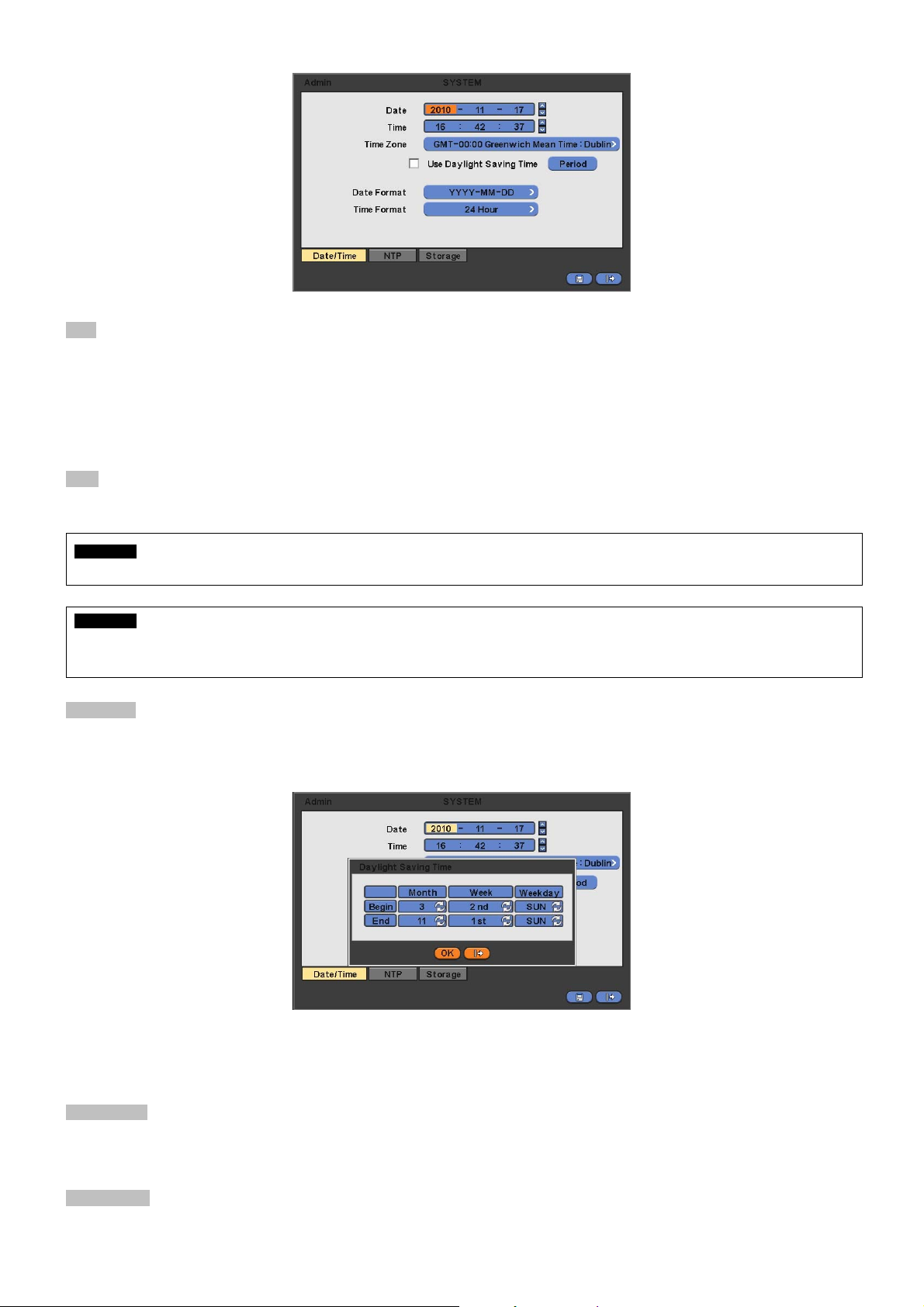
Date
This menu will allow user to adjust the settings.
Please follow the procedure below for time adjustment.
① Click ( ) items (Y, M, D) to change. A designated item will be highlighted in a box (Y: Year, M: Month and D: Date).
② Adjust the number by clicking ( ) ▲, ▼ buttons on the right-hand side.
③ Repeat the same procedure to change Y, M and D.
Time
This menu will allow user to adjust the current time. The adjustment procedure is same as of Date.
CAUTION
IF ADJUSTED DATE/TIME IS PRIOR TO RECORDED DATA, DATA AFTER NEW DATE/TIME MAY BE ERASED.
CAUTION
ANY CHANGE IN DATE/TIME IS IMMEDIATELY APPLIED ON VIEWING SCREEN (LIVE), BUT THE DATE/TIME WHEN THE RECORDING
WAS DONE IS NOT CHANGED. MAKE SURE TO REBOOT DVR AFTER CHANGING THE DATE/TIME. DO NOT FORGET TO EXECUTE
SHUTDOWN (SYSTEM>Shutdown) BEFORE REBOOT.
Time Zone
Please click ( ) Time Zone frame to see the list of nations and choose one.
Click ( ) a check box next to Use Daylight Saving Time. When user dwells in a region of DST area, please check it (i.e. ).
If DST is observed, please click ( ) Period and the following screen will appear.
Adjust the dates of beginning (Begin) and end (End) of DST by ‘Month/Week/Weekday’.
Click ( ) the numbers in ‘Month/Week/Weekday’ for adjustment.
Choose ‘OK’ to confirm the setting.
Date Format
Set date indication format. Please click ( ) Date Format frame to select a format from the list.
Time Format
Set time indication format. Please click ( ) Time Format frame to select a format from the list.
29
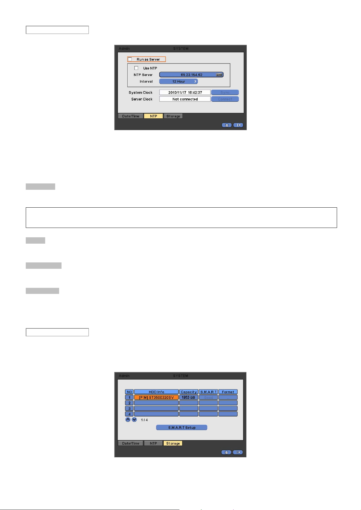
NTP
When user complete Date/Time input, please click ( ) NTP and the following screen will appear.
This menu is for accurate setting of time of day clock in DVR.
User may check only one of Run as Server and Use NTP.
- Run as Server: NTP cannot be used in a non-networked environment (Intranet environment). In this case, DVR with Run
as Server functions as Time Server.
- Use NTP: Connect to Internet to synchronize DVR clock with Network Time Server’s clock.
NTP Server
Click ( ) keyboard icon in NTP Server frame and the virtual keyboard will appear. Input IP address of NTP server.
(NOTE)
Currently used NTP is administered by pool.ntp.org and its IP address is 65.23.154.62. However, users are allowed to use IP address of any
NTP site.
Interval
Set clock-update-interval from NTP Server. Normally, user can adjust 1 hour up to 24 hours.
System Clock
Display DVR clock.
Server Clock
Display NTP Server’s clock if Internet is connected to Server Clock. If not displaying, please click ( ) Connect button.
When Server Clock is displayed, please click ( ) Sync button to synchronize NTP Server’s clock with DVR clock.
Choose ‘OK’ to confirm the clock synchronization.
Storage
When user completes NTP input, please click ( ) save and the following screen will appear.
Set S.M.A.R.T. (Self-Monitoring Analysis and Reporting Technology) function for HDD format and auto-display of HDD
information. DVD-RW is not shown here.
Clicking Up and Down button for checking up the status of HDD and DVD-RW devices.
Using E-SATA port will allow users to connect up to maximum 12 HDD +1 DVD-RW.
When user installs full storage device and DVD-RW including two e-SATA storage, then following procedures will be listed
30
 Loading...