


A Textron Company

MANUAL INFORMATION
For any questions on material contained in this manual, contact a representative for clarification.
Read and understand all labels located on the vehicle. Always replace any damaged or missing labels.
On steep hills it is possible for vehicles to coast at greater than normal speeds encountered on a flat surface. To prevent loss of vehicle control and possible serious injury, speeds should be limited to no more than the maximum speed on level ground. (See vehicle specification.) Limit speed by applying the service brake.
Catastrophic damage to the drive train components due to excessive speed may result from driving the vehicle above specified speed. Damage caused by excessive speed may cause a loss of vehicle control, is costly, is considered abuse and will not be covered under warranty.
Be sure that this manual remains as part of the permanent service record should the vehicle be re-sold.
Throughout this guide, NOTE, CAUTION and WARNING will be used.
A NOTE indicates a condition that should be observed.
A CAUTION indicates a condition that may result in damage to the vehicle.
A WARNING indicates a hazard- ! 


 ! ous condition which could result
in severe injury or death.
Please observe these notes, cautions, and warnings; be aware that servicing a vehicle requires mechanical skill and a regard for conditions that could be hazardous. Improper service or repair may damage the vehicle or render it unsafe.
Engine exhaust from this product ! 


 ! contains chemicals known, in certain quantities, to cause cancer,
birth defects, or other reproductive harm.
 The exhaust emissions of this vehicles’ engine complies with regulations set forth by the Environmental Protection Agency (EPA) of the United States of America
(USA) at time of manufacture. Significant fines could result from modifications or tampering with the engine, fuel, ignition or air intake systems.
Battery posts, terminals and relat- ! 


 ! ed accessories contain lead and lead compounds. Wash hands
after handling.
This spark ignition system meets all requirements
 of the Canadian Interference-Causing Equipment Regulations.
Ce système d'allumage par étincelle de véhicule respecte toutes les exigences du Règlement sur le matériel brouilleu du Canada.
OWNER’S MANUAL & SERVICE GUIDE
ST 480
E-Z-GO Division of Textron Inc. reserves the right to make design changes without obligation to make these changes on units previously sold and the information contained in this manual is subject to change without notice.
E-Z-GO Division of Textron Inc. is not liable for errors in this manual or for incidental or consequential damage that result from the use of material in this manual.
CUSTOMER SERVICE DEPARTMENT IN USA PHONE: 1-800-241-5855 FAX: 1-800-448-8124
OUTSIDE USA PHONE: 010-1-706-798-4311 FAX: 010-1-706-771-4609
E-Z-GO DIVISION OF TEXTRON INC., P.O. BOX 388 AUGUSTA, GEORGIA 30903-0388 USA
i

NOTES
To obtain a copy of the limited warranty applicable to the vehicle, call or write a local Distributor, authorized Branch or the Warranty Department with vehicle serial number and manufacture date code.
The use of non Original Equipment Manufacturer (OEM) approved parts may void the warranty.
Tampering with or adjusting the governor to permit vehicle to operate at above factory specifications will void the vehicle warranty.
When servicing engines, all adjustments and replacement components must be per original vehicle specifications in order to maintain the United States of America Federal and State emission certification applicable at the time of manufacture.
BATTERY PROLONGED STORAGE
All batteries will self discharge over time. The rate of self discharge varies depending on the ambient temperature and the age and condition of the battery.
A fully charged battery will not freeze in winter temperatures unless the temperature falls below -75° F (-60° C).
ii

TITLE |
|
|
PAGE |
MANUAL INFORMATION.......................... |
Inside Front Cover |
||
NOTES ...................................................................................... |
|
|
i |
SAFETY INFORMATION ...................................................... |
|
2-1 |
|
OPERATION AND SERVICE INFORMATION |
.....................3-1 |
||
BEFORE INITIAL USE ................................................................................ |
|
3-1 |
|
Fig. 1 |
Initial Service Chart .......................................................... |
|
3-2 |
TERRAIN ..................................................................................................... |
|
|
3-2 |
VEHICLE CAPACITY .................................................................................. |
|
3-2 |
|
MODIFICATIONS TO VEHICLE .................................................................. |
|
3-3 |
|
COMMON SENSE OPERATION ................................................................. |
|
3-3 |
|
POWER CONSUMPTION ........................................................................... |
|
3-3 |
|
ENVIRONMENTAL CONCERNS ................................................................ |
|
3-4 |
|
OPTIONAL WINCH ..................................................................................... |
|
3-4 |
|
OPERATION OF THE WINCH ............................................................... |
|
3-4 |
|
Fig. 2 |
Winch Mounted to Vehicle ................................................ |
|
3-4 |
Fig. 3 |
Winch Remote Control ..................................................... |
|
3-5 |
Fig. 4 |
Winch Clutch Knob ........................................................... |
|
3-5 |
WINCH APPLICATIONS ........................................................................ |
|
3-5 |
|
Fig. 5 Never Operate Winch with Less Than |
|
||
|
Five Turns Around Drum .................................................. |
|
3-6 |
Fig. 6 |
Do Not Hook Cable to Itself .............................................. |
|
3-7 |
Fig. 7 |
Use a Nylon Sling and Install a Damper when Winching .3-7 |
||
Fig. 8 |
Do Not Pull at Angle ......................................................... |
|
3-8 |
CONTROLS AND INDICATORS ................................................................. |
|
3-8 |
|
KEY/LIGHT SWITCH ............................................................................. |
|
3-8 |
|
Fig. 9 |
Key/Light Switch, Low Oil Pressure Light and Fuel Gauge 3-8 |
||
DIRECTION SELECTOR ....................................................................... |
|
3-9 |
|
Fig. 10 |
Console Controls ............................................................ |
|
3-9 |
CHOKE ................................................................................................... |
|
|
3-9 |
FUEL GAUGE ........................................................................................ |
|
3-9 |
|
LOW OIL PRESSURE INDICATOR LIGHT ........................................... |
|
3-9 |
|
ACCELERATOR PEDAL ........................................................................ |
|
3-9 |
|
Fig. 11 |
Accelerator, Brake and Horn ........................................ |
|
3-10 |
TABLE OF CONTENTS |
|
TITLE |
PAGE |
SERVICE BRAKE PEDAL ................................................................... |
3-10 |
PARK BRAKE ...................................................................................... |
3-10 |
HORN ................................................................................................... |
3-10 |
DIFFERENTIAL LOCK ......................................................................... |
3-10 |
LOAD BED ................................................................................................ |
3-11 |
ELECTRIC LIFT BED OPERATION .................................................... |
3-11 |
Fig. 12 Electric Lift Switch ........................................................ |
3-11 |
OPERATING THE VEHICLE ..................................................................... |
3-12 |
RUN-IN ................................................................................................. |
3-13 |
Fig. 13 Check Oil Level on Dipstick ......................................... |
3-13 |
COLD STARTING ................................................................................ |
3-13 |
STARTING AND DRIVING .................................................................. |
3-14 |
STARTING THE VEHICLE ON A HILL ................................................ |
3-14 |
COASTING .......................................................................................... |
3-14 |
FUEL .................................................................................................... |
3-15 |
Fig. 14 Fueling ......................................................................... |
3-15 |
BATTERY ............................................................................................. |
3-15 |
LABELS AND PICTOGRAMS .............................................................. |
3-16 |
SUN TOP AND WINDSHIELD ............................................................. |
3-16 |
12 VOLT POWER OUTLET ................................................................. |
3-16 |
Fig. 15 12 Volt Power Outlet .................................................... |
3-16 |
TOWING A TRAILER ........................................................................... |
3-16 |
VEHICLE CLEANING AND CARE ........................................................... |
3-17 |
VEHICLE CLEANING .......................................................................... |
3-17 |
VEHICLE CARE PRODUCTS .............................................................. |
3-17 |
REPAIR ..................................................................................................... |
3-18 |
LIFTING THE VEHICLE ....................................................................... |
3-18 |
Fig. 16 Lifting the Vehicle ......................................................... |
3-19 |
WHEELS AND TIRES .......................................................................... |
3-19 |
Tire Repair ..................................................................................... |
3-19 |
Wheel Installation .......................................................................... |
3-20 |
Fig. 17 Wheel Installation ......................................................... |
3-21 |
LIGHT BULB REPLACEMENT ............................................................ |
3-21 |
Fig. 18 Headlight and Turn Signal Bulb Replacement ............. |
3-21 |
Fig. 19 Tail and Brake Light Bulb Replacement ....................... |
3-21 |
FUSE REPLACEMENT ........................................................................ |
3-21 |
VEHICLE WITH A DISCHARGED BATTERY ...................................... |
3-22 |
TRANSPORTING VEHICLE ..................................................................... |
3-22 |
|
1-1 |

TABLE OF CONTENTS
TITLE |
|
PAGE |
TOWING .............................................................................................. |
|
3-22 |
NEUTRAL LOCK ................................................................................. |
3-22 |
|
Fig. 20 |
Neutral Lock ................................................................. |
3-23 |
HAULING ............................................................................................. |
|
3-22 |
SERVICE AND MAINTENANCE .............................................................. |
3-23 |
|
SERIAL NUMBER PLATE LOCATION ................................................ |
3-25 |
|
Fig. 21 |
Serial Number Plate Location ...................................... |
3-25 |
PERIODIC SERVICE SCHEDULE ..................................................... |
3-26 |
|
Fig. 22 |
Periodic Service Schedule ........................................... |
3-26 |
TIRE INSPECTION .............................................................................. |
3-28 |
|
SEAT PROP ........................................................................................ |
|
3-28 |
Fig. 23 |
Seat Prop ..................................................................... |
3-29 |
REPLACING THE FUEL FILTER ........................................................ |
3-29 |
|
CHECKING THE OIL LEVEL ............................................................... |
3-29 |
|
Fig. 24 |
Oil Fill Cap, Dipstick and Fuel Filter ............................. |
3-30 |
Fig. 25 |
Clean Entire Dipstick ................................................... |
3-30 |
Fig. 26 |
Check Oil Level on Dipstick ......................................... |
3-30 |
CHANGING THE OIL ........................................................................... |
3-30 |
|
Fig. 27 |
Oil Viscosity Chart ....................................................... |
3-31 |
CHANGING THE OIL FILTER ............................................................. |
3-32 |
|
Fig. 28 |
Oil Drain and Filter ....................................................... |
3-32 |
LUBRICATION |
..................................................................................... |
3-32 |
Fig. 29 |
Lubrication Points ........................................................ |
3-32 |
AIR CLEANER INSPECTION AND REPLACEMENT ......................... |
3-33 |
|
Pre-Cleaner Service ...................................................................... |
3-33 |
|
Cartridge Service ........................................................................... |
3-33 |
|
Fig. 30 |
Air Cleaner ................................................................... |
3-33 |
REAR AXLE ......................................................................................... |
|
3-34 |
Checking the Lubricant Level ........................................................ |
3-34 |
|
Fig. 31 |
Add, Check and Drain Rear Axle Lubricant ................. |
3-34 |
STARTER/GENERATOR BELT TENSION ......................................... |
3-34 |
|
Fig. 32 |
Check Belt Tension with Gauge .................................. |
3-35 |
Fig. 33 |
Check Belt Tension with Finger ................................... |
3-35 |
Adjusting the Belt .......................................................................... |
3-35 |
|
Fig. 34 |
Adjust Belt Tension ...................................................... |
3-35 |
BATTERY CLEANING ......................................................................... |
3-36 |
|
Fig. 35 |
Preparing Acid Neutralizing Solution ........................... |
3-36 |
AIR INTAKE AND COOLING FINS ...................................................... |
3-36 |
|
Fig. 36 |
Cleaning Air Intake and Cooling Fins .......................... |
3-37 |
1-2
TITLE |
PAGE |
SPARK PLUGS ................................................................................... |
3-37 |
BRAKES .............................................................................................. |
3-37 |
Daily Brake Test ............................................................................ |
3-37 |
PROLONGED STORAGE ................................................................... |
3-38 |
HARDWARE ........................................................................................ |
3-38 |
Fig. 37 Torque Specifications and Bolt Grades ....................... |
3-39 |
CAPACITIES AND REPLACEMENT PARTS ..................................... |
3-40 |
Fig. 38 Capacities and Replacement Parts ............................. |
3-40 |
GENERAL SPECIFICATIONS.............................................. |
4-1 |
|
ST 480 .................................................................................................... |
|
4-1 |
Fig. 1 |
Vehicle Dimensions .......................................................... |
4-2 |
Fig. 2 |
Vehicle Incline Specifications ........................................... |
4-3 |
Fig. 3 |
Vehicle Turning Clearance Diameter................................ |
4-4 |
LIMITED WARRANTY .......................................................... |
5-1 |
|
DECLARATION OF CONFORMITY ..................................... |
6-1 |
|
LABELS AND PICTOGRAMS ............................. |
APPENDIX A |
|

SAFETY INFORMATION
Read all of manual to become thoroughly familiar with this vehicle. Pay particular attention to all Notes, Cautions and Warnings
The Owner’s Manual and Service Guide has been designed to assist in maintaining the vehicle in accordance with procedures developed by the manufacturer. Adherence to these procedures and trouble-shooting tips will ensure the best possible service from the product. To reduce the chance of personal injury and/or property damage, the following instructions must be carefully observed:
GENERAL
Many vehicles are used for a variety of tasks beyond the original intended use of the vehicle; therefore, it is impossible to anticipate and warn against every possible combination of circumstances that may occur.
Good common sense and prudent driving practices do more to prevent accidents and injury than all of the warnings and instructions combined. The manufacturer strongly suggests that the owner-operator read this entire Owner’s Manual and Service Guide paying particular attention to the CAUTIONS and WARNINGS contained therein. It is further recommended that other operators be encouraged to do the same.
If you have any questions, contact your closest representative or write to the address on the back cover of this publication, Attention: Product Service Department.
•E-Z-GO Division of Textron Inc. is not liable for errors in this manual or for incidental or consequential damages that result from the use of the material in this manual.
•E-Z-GO Division of Textron Inc. reserves the right to make design changes without obligation to make these changes on units previously sold and the information contained in this manual is subject to change without notice.
•This vehicle conforms to the current applicable standard for safety and performance requirements.
•These vehicles are designed and manufactured for off-road use. They do not conform to Federal Motor Vehicle Safety Standards of the United States of America (USA) and are not equipped for operation on public
streets. Some communities may permit these vehicles to be operated on their streets on a limited basis and in accordance with local ordinances.
•Vehicle capacity is limited to a maximum of two persons.
•Never modify the vehicle in any way that will alter the weight distribution of the vehicle, decrease its stability or increase the speed beyond the factory specification. Such modifications can cause serious personal injury or death. Modifications that increase the speed and or weight of the vehicle will extend the stopping distance and may reduce the stability of the vehicle. Do not make any such modifications or changes. The manufacturer prohibits and disclaims responsibility for any such modifications or any other alteration which would adversely affect the safety of the vehicle.
GENERAL OPERATION
The following information is very important in the operation of the vehicle. The operator should read, understand and always observe the following:
•Use the vehicle in a responsible manner and maintain the vehicle in safe operating condition.
•Read, understand and observe all warnings and operation instruction labels affixed to the vehicle.
•Follow all safety rules established in the area where the vehicle is being operated.
•Reduce speed to compensate for unsuitable terrain or conditions.
•Apply service brake to control speed on steep grades.
•Reduce speed in wet areas.
•Use extreme caution and reduced speed when approaching sharp or blind turns.
•Use extreme caution and reduced speed when driving over loose terrain.
•Use extreme caution and reduced speed in areas where pedestrians are present.
2-1

SAFETY INFORMATION
Read all of manual to become thoroughly familiar with this vehicle. Pay particular attention to all Notes, Cautions and Warnings
MAINTENANCE
The following information is very important in the maintenance of the vehicle. The person performing maintenance procedures should read, understand and always observe the following:
•Maintain your vehicle in accordance with the manufacturer’s periodic service schedule.
•Ensure that mechanics performing repairs are trained and qualified to do so.
•Follow the manufacturer’s directions if you perform maintenance on your own vehicle. Be sure to disable the vehicle before performing any maintenance. Disabling includes removing the key from the key switch and removal of a battery wire.
•Insulate any tools used within the battery area in order to prevent sparks or battery explosion caused by shorting the battery terminals or associated wiring. Remove the battery or cover exposed terminals with an insulating material.
•Check the polarity of each battery terminal and be sure to rewire the battery correctly.
•Use specified replacement parts. Never use replacement parts of lesser quality.
•Use only tools recommended by the manufacturer.
•Determine that tools and procedures not specifically recommended by the manufacturer will not compromise the safety of personnel nor jeopardize the safe operation of the vehicle.
•Support the vehicle using wheel chocks and jack stands. Never get under a vehicle that is supported by a jack. Lift the vehicle in accordance with the manufacturer’s instructions.
•Never attempt to perform vehicle maintenance in an area where exposed flame is present or persons are smoking.
•Be aware that a vehicle that is not performing as designed is a potential hazard and must not be operated until inspected and repaired.
•The manufacturer cannot anticipate all dangerous situations. People attempting to maintain or repair the vehicle must have the skill and experience to recognize and protect themselves from potential dangerous situations. These situations could result in severe personal injury or death and damage to the vehicle. Use extreme caution and if unsure as to the potential for injury refer the repair or maintenance to a qualified mechanic.
•Test drive the vehicle after any repairs are made or maintenance procedures performed to assure the vehicle is safe to return to service. All tests must be conducted in a safe area that is free of both vehicular and pedestrian traffic.
•Replace damaged or missing warning, caution or information labels.
•Keep complete records of the maintenance history of the vehicle.
VENTILATION
•Always store gasoline vehicles in a well ventilated area to prevent gasoline fumes from accumulating.
•Never fuel a vehicle in an area that is subject to flame or spark. Pay particular attention to natural gas or propane water heaters and furnaces.
•Never work around or operate a vehicle in an environment that does not ventilate exhaust gases from the area. Carbon monoxide is a dangerous gas that can cause unconsciousness and is potentially lethal.
2-2

OPERATION AND SERVICE INFORMATION
Read all of manual to become thoroughly familiar with this vehicle. Pay particular attention to all Notes, Cautions and Warnings
\
Thank you for purchasing a light duty utility vehicle. Before driving the vehicle, we ask you to spend some time reading this Owner’s Manual and Service Guide and the Operating and Maintenance Instructions manual provided by the engine manufacturer. These manuals contain the information that will assist you in the safe operation of the vehicle. They will also assist you in maintaining this highly reliable vehicle. Some illustrations may show items that are optional for your vehicle.
This vehicle has been designed and manufactured as a ‘World Vehicle’. Some countries have individual requirements to comply with their specifications; therefore, some sections may not apply in your country.
Most of the service procedures in this guide can be accomplished using common automotive hand tools. Contact your service representative on servicing the vehicle in accordance with the Periodic Service Schedule.
Service Parts Manuals, Technician’s Repair and Service Manuals and engine Repair Manuals are available from a local Distributor, an authorized Branch or the Service Parts Department. When ordering parts or requesting information for your vehicle, provide vehicle model, serial number and manufacture date code.
BEFORE INITIAL USE
 Record the four digit key number and store in a safe place. Individual keys can only be replaced if the key number is known. Without a key number, the entire ignition
switch will have to be replaced if keys are lost.
Read, understand and follow the safety label on the instrument panel (Ref Appendix A). Be sure you understand how to operate the vehicle, its equipment and how to use it safely. Maintaining good performance depends to a large extent on the operator.
Improper use of this vehicle could ! 


 ! result in severe injury or death. The
ST Series vehicle is a light duty utility vehicle. It is NOT an all terrain vehicle (ATV).
This vehicle is not a toy and using it while engaging in horseplay is dangerous.
Plan carefully before using the vehicle to go significant distances over questionable terrain. Remember that a one hour drive may take many hours to walk out should you run out of fuel or be stranded by becoming stuck on unsuitable terrain.
Hydrogen gas is generated as a natural part of the lead acid battery charging process. A 4% concentration of hydrogen gas is explosive and could cause severe injury or death. Charging must take place in an area that is adequately venti-
3-1

OPERATION AND SERVICE INFORMATION
Read all of manual to become thoroughly familiar with this vehicle. Pay particular attention to all Notes, Cautions and Warnings
lated (minimum of 5 air exchanges per hour).
To reduce the chance of battery explosion that could result in severe injury or death, never smoke around or charge batteries in an area that has open flame or electrical equipment that could cause an electrical arc.
Before a new vehicle is put into operation, the items shown in the INITIAL SERVICE CHART must be performed (Ref Fig. 1 on page 3-2).
|
|
|
|
|
ITEM |
SERVICE OPERATION |
|
|
|
|
|
|
Battery |
Charge battery |
|
|
|
|
|
|
Seats |
Remove protective plastic covering |
|
|
|
|
|
|
Brakes |
Check operation and adjust if necessary |
|
|
|
|
|
|
|
Check hydraulic brake fluid level |
|
|
|
|
|
|
Tires |
Check air pressure (see SPECIFICATIONS) |
|
|
Fuel |
Fill tank with correct fuel |
|
|
|
|
|
|
Engine |
Check oil level (Initial change after 5 - 8 hours) |
|
|
|
|
|
|
Keys |
Record key number and store in safe location |
|
|
|
|
|
|
|
|
|
|
|
Fig. 1 Initial Service Chart |
|
Vehicle battery must be fully charged before initial use.
Check for correct tire inflation. See GENERAL SPECIFICATIONS.
Check for oil or fuel leaks that could have developed in shipment from the factory.
Check for a firm brake pedal. Determine and record braking distance required to stop vehicle for future brake performance tests.
Record and keep key number.
Remove the protective clear plastic, that protect the seat bottom and back rest during shipping, before placing the vehicle in service.
TERRAIN
The vehicle is designed for use on improved roads (but not on public highways). The vehicle may also be used on established trails or open terrain that is free from stumps, large rocks or holes.
The vehicle should not be used to cross water.
VEHICLE CAPACITY
Due to the variety of ways the vehi- ! 


 ! cle may be used, it is important that the operator consider any potential
hazards before use to prevent serious injury or death.
The vehicle may be used to transport a maximum of two people within the operator/passenger compartment and cargo in the load bed. Never carry passengers in the load bed. The total payload is 800 lbs. (363 kg). The weight of the driver and passenger plus any options or accessories must be deducted from the total payload rating to determine the load bed capacity. Remember that towing a trailer will reduce the payload of the vehicle itself.
Remember that volume of your load can be misleading. Loading the vehicle to its rated capacity with dry sand, fertilizer, sod, etc. can be handled with complete safety. The same load when wet will grossly overload the vehicle and increase the potential for roll over and damage to the vehicle.
3-2
OPERATION AND SERVICE INFORMATION
Read all of manual to become thoroughly familiar with this vehicle. Pay particular attention to all Notes, Cautions and Warnings
MODIFICATIONS TO VEHICLE
Changes to the weight distribution ! 


 ! or the center of gravity may make it unstable or prone to roll over which
could result in injury or death to the operator or passenger.
Do not modify the vehicle in any manner that will change the weight distribution of the vehicle. Changes to the weight distribution or the center of gravity may make it unstable or prone to roll over which could result in injury or death to the operator or passenger.
COMMON SENSE OPERATION
This vehicle is not a toy. If not operated properly and responsibly, it can cause severe injury or death to the operator, passenger or bystanders. All operators should possess a valid driver’s license. Children should not be permitted to operate the vehicle. Children may not have the skill, judgement or strength to operate this or similar vehicles.
Alcohol, drugs and many over the counter medications reduce the ability of the driver to operate the vehicle safely. Always review side effects of any medication with a doctor or pharmacist before operating vehicle.
Protective clothing and an approved motorcycle helmet are recommended for operator and passenger at all times.
When driving at full speed on a dirt road, loose surfaces or wet grass, vehicle stopping distance will increase. If the vehicle is fully loaded, it will take longer to stop than with no load. When operating vehicle in wet weather conditions, remember that the brakes may need to be lightly applied in order to provide enough friction to dry the brake unit. If wet, the brakes will lose much of their effect.
Slow down when in unfamiliar terrain. Slow down when cresting a hill in an area that you are unfamiliar with.
Some hills are too steep to climb. If you attempt to climb a hill that is too steep or if you are unable to achieve adequate traction, do not attempt to turn around on the hill. Slowly back straight down the hill using the service brake to control speed.
POWER CONSUMPTION
The vehicle uses a combination starter/generator to both start the engine and charge the battery. The engine will not idle; therefore, the battery cannot be charged while the vehicle is stopped. Do not operate accessory items (such as accessory lights, radios, winch, etc.) excessively while the vehicle is stopped.
Overuse of accessories may drain the battery and leave insufficient
reserve to start the vehicle.
The generator is only capable of supplying 35 amps; therefore, operation of all accessories could result in the discharge of the battery even though the engine is running and the generator operating. Discharging the battery is known as deep cycling. The battery is not a deep cycle model, but is a starting battery. Multiple deep cycling of the battery will result in the premature failure of the battery.
Vehicle battery must be fully charged before initial use.
Hydrogen gas is generated as a nat- ! 


 ! ural part of the lead acid battery charging process. A 4% concentration of hydrogen gas is explosive and could cause severe
3-3

OPERATION AND SERVICE INFORMATION
Read all of manual to become thoroughly familiar with this vehicle. Pay particular attention to all Notes, Cautions and Warnings
injury or death. Charging must take place in an area that is adequately ventilated (minimum of 5 air exchanges per hour).
To reduce the chance of battery explosion that could result in severe injury or death, never smoke around or charge batteries in an area that has open flame or electrical equipment that could cause an electrical arc.
ENVIRONMENTAL CONCERNS
As a responsible user, practice respect for all wildlife and their habitat. Respect private property and comply with all local laws and regulations governing the use of light duty utility vehicles. Do not tamper with the exhaust system or governor. The exhaust system has been tuned to the engine for maximum performance. Removal or modification of the exhaust is annoying to other people and will not improve the performance of the vehicle.
To prevent severe injury or death ! 


 ! while driving, be aware of the follow-
ing:
Environmental hazards such as steep slopes, overhanging limbs, etc.
Danger of fire when vehicle is operated over dry combustible organic material.
When driving, be aware of environmental hazards such as steep slopes, overhanging limbs, etc. Be aware of the danger of fire when the vehicle is operated over dry combustible organic material.
OPTIONAL WINCH
This vehicle may be equipped with an optional winch. Read, understand and follow all of the following information on the operation and use of the winch before attempting to operate it.
OPERATION OF THE WINCH
The winch can be mounted at the front or rear of the vehicle and moved to accommodate different situations. At the front, it is mounted under the center of the front cowl to a bracket attached to the front axle as shown (Ref Fig. 2 on page 3-4). At the rear, the winch is mounted upside down in the hitch receiver.
If mounting winch at rear of vehicle, the winch must be mounted upside down.
Winch shown mounted at front of vehicle |
Front Axle |
Spring Pin |
Clevis Pin |
Fig. 2 Winch Mounted to Vehicle
3-4

OPERATION AND SERVICE INFORMATION
Read all of manual to become thoroughly familiar with this vehicle. Pay particular attention to all Notes, Cautions and Warnings
Before moving the winch, unplug the winch connector from the wire harness. To move the winch from one end of the vehicle to the other, remove the spring pin, pull out the clevis pin and remove the winch mount tube from the receiver. Move to opposite end of vehicle and install by inserting clevis pin and securing with spring pin. Plug the winch connector into wire harness.
The winch remote control plugs into the receptacle on the driver side of the seat support (Ref Fig. 3 on page 3-5).
operate winch while sitting in passenger seat. Read the following section (Winch Applications) before attempting to operate winch.
ENGAGED |
LOCKED OUT |
|
Pull out |
Clutch Knob |
Turn 90 0 |
Remote Control
Receptacle
Fig. 3 Winch Remote Control
To unwind the cable, locate the clutch knob on the winch. Pull out knob and rotate 90° to lock out. Using handsaver bar, pull cable from winch drum. Leave at least five turns of cable on drum. Re-engage drum by turning clutch knob 90°, returning it to original position (Ref Fig. 4 on page 3-5).
To wind cable, use handsaver bar to keep tension on the cable while activating remote. When winding cable, make sure the cable winds tightly and evenly onto the drum leaving no gaps that could cause premature wear to the cable. When using winch under a load, operate the remote control from as far to the side of the vehicle as possible. Do not
Fig. 4 Winch Clutch Knob
WINCH APPLICATIONS
The winch may be used for a number of purposes, including pulling the vehicle if it loses traction on unsuitable terrain.
Improper use of the winch could ! 


 ! result in a number of conditions that could cause severe injury or death
to operator, occupants of vehicle or bystander.
It is impossible to predict all conditions that the winch could be used, therefore the following warnings should not be considered as complete. Before operating the winch, consider the possible dangers and take precautions to protect yourself, your passenger and any bystanders.
To prevent severe injury or death to ! 


 ! operator, occupants or bystanders, select the object to which the cable
is attached with the following considerations:
Make sure the object cannot be pulled over or otherwise damaged.
3-5

OPERATION AND SERVICE INFORMATION
Read all of manual to become thoroughly familiar with this vehicle. Pay particular attention to all Notes, Cautions and Warnings
The object the winch is attached to could fall on the vehicle and it’s occupants.
If attaching the winch to a dead tree, a section could fall.
When pulling vehicle with winch, pull straight only. Do not permit the cable to contact the side of the drum.
Do not pull vehicle at angle. If the ! 


 ! vehicle is pulled at an angle, it could turn over causing severe injury or death to anyone in the area. The winch cable could also
become overstressed and break causing severe injury or death to anyone struck by the cable.
If the vehicle becomes stuck or ‘hung up’ on an obstruction, the vehicle may be moved using the winch.
The winch may be installed in either the front or rear receiver and held in place with the locking pin provided.
To prevent severe injury or death, ! 


 ! read and understand the following
before attempting to use the winch:
The winch is not intended to be used in any hoisting operation.
The rolling load capacity of the winch decreases with the steepness of the slope.
The winch is designed for intermittent duty only. The electric motor should not be allowed to become excessively hot. If the motor becomes uncomfortably hot to the touch, stop winching and allow the motor to cool.
Always wear thick leather gloves when handling the wire cable.
Replace frayed wire cable with a direct factory replacement only.
Never operate the winch with less than five (5) full turns of cable around the drum (Ref Fig. 5 on page 3-6).
Fig. 5 Never Operate Winch with Less Than
Five Turns Around Drum
If the winch motor stalls from overloading, do not continue to activate the winch remote control. The wire cable may become overstressed.
Do not attempt to pull loads exceeding 1500 lbs. (680 kg).
To pull out the cable, the free spool clutch knob must be used. Pull out and rotate the knob. If the cable is under any load the clutch may not release easily. Jog out some of the cable to release the tension and operate clutch. Pull out the desired amount of cable and secure. Engage the drum by rotating the knob until it snaps in place. Never operate the winch unless the clutch is engaged.
Have all persons and pets leave the area while operating winch. Never allow anyone to remain in the vehicle.
3-6

OPERATION AND SERVICE INFORMATION
Read all of manual to become thoroughly familiar with this vehicle. Pay particular attention to all Notes, Cautions and Warnings
To prevent damage to the wire cable, never hook the cable to itself. Always use a nylon sling (Ref Fig. 6 on page 3-7) (Ref Fig. 7 on page 3-7).
Ref Wca 2 |
Fig. 6 Do Not Hook Cable to Itself
Damper |
Nylon |
Sling |
Ref Wcd 2 |
Fig. 7 Use a Nylon Sling and Install a Damper when Winching
Unplug the winch switch before working on the winch drum in order to prevent inadvertent operation.
Stay clear of the winch, the cable and the cable hook. Place a heavy cloth, jacket or blanket over the cable to act as a damper should the cable break when operating the winch (Ref Fig. 7 on page 3-7).
Remember that the winch operation will drain the battery and may leave insufficient power to start the vehicle.
When operating the winch, keep the entire area in view.
Never release the free spool clutch while the cable is under load.
Never work around the winch drum or the winch cable while it is under tension.
When operating winch, take up slack slowly. Stop winch before cable becomes tight and inspect all winching connections. Check winch attachment, hook attachment, nylon sling (if required) and load attachment.
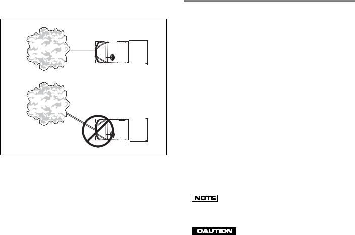
Do not pull at an angle. This will cause the wire cable to pile up on one end of the winch. This may jam the winch causing damage to the cable and/or the winch. Pulling the vehicle at an angle can cause damage to the front suspension and may cause the vehicle to overturn. When pulling vehicle, pull straight only (Ref Fig. 8 on page 3-8).
If the vehicle is being used as an anchor to winch a load, it should have the parking brake set and chocks installed on
3-7
OPERATION AND SERVICE INFORMATION
Read all of manual to become thoroughly familiar with this vehicle. Pay particular attention to all Notes, Cautions and Warnings
Correct
Incorrect
Ref Wps 2
Fig. 8 Do Not Pull at Angle
all wheels.
Never use the winch to lift people or other overhead loads.
Do not use the winch to secure loads. Use a tie down designed for the job.
Do not apply shock loads to the winch.
Do not attempt to modify or weld the winch.
3-8
CONTROLS AND INDICATORS
Vehicle controls and indicators consist of:
•key/light switch
•direction selector
•choke
•fuel gauge
•low oil pressure light
•accelerator pedal
•brake pedal
•park brake
•horn
•differential lock
KEY/LIGHT SWITCH
Located on the dash panel, this switch enables the basic electrical system of the vehicle to be turned on and off by turning the key. To prevent inadvertent operation of the vehicle when left unattended, the key should be turned to the ‘OFF’ position and removed (Ref Fig. 9 on page 3-9).
If the vehicle is equipped with lights, the key switch has a position to operate them, indicated by the light icon.
If the vehicle is equipped with factory installed custom accessories, some accessories remain opera-
tional with the key switch in the ‘OFF’ position.
DIRECTION SELECTOR
T o r e d u c e t h e p o s s i b i l i t y o f

OPERATION AND SERVICE INFORMATION
Read all of manual to become thoroughly familiar with this vehicle. Pay particular attention to all Notes, Cautions and Warnings
Key/Light Switch |
Fuel |
||
Gauge |
|||
OFF |
ON |
|
F |
E |
|
||
|
|
||
|
|
FUEL |
|
 Low Oil Pressure
Indicator Light
Fig. 9 Key/Light Switch, Low Oil Pressure Light and Fuel Gauge
component damage, the vehicle must be completely stopped before moving the direction selector.
Located on the console between the seats, this lever permits the selection of either forward or reverse (Ref Fig. 10 on page 3-9). The vehicle should be left in forward when unattended.
CHOKE
The choke is used to aid cold starting (Ref Fig. 10 on page 3-9). See ‘Cold Starting’ (Refer to page 3-14) for instructions on using the choke properly.
FUEL GAUGE
An electric fuel gauge is located to the right side of the key/light switch. It indicates the amount of fuel in the tank (Ref Fig. 9 on page 3-9).
LOW OIL PRESSURE INDICATOR LIGHT
A low oil pressure indicator light is located on the dash panel (Ref Fig. 9 on page 3-9). If oil pressure drops below 1 - 4 psi (.1 - .2 kg/cm2), the oil pressure switch will activate the light. Check oil level (Refer to page 3-
Choke |
Parking |
|
Brake |
||
|
||
Direction |
|
|
Selector |
Differential |
|
|
||
|
Locked |
|
|
Differential |
|
|
Lock Lever |
|
|
(Stop Vehicle |
|
|
Before Moving |
|
|
Lever) |
|
Differential |
|
|
Unlocked |
|
|
|
75694G01 |
Fig. 10 Console Controls
29). If oil level is between ADD and FULL mark on dipstick, a mechanical problem exists within the engine and the vehicle must not be driven. Contact a local Distributor or authorized Branch.
To prevent engine damage, do not operate engine until oil pressure is corrected. Do not overfill engine. Too much oil may
cause smoking or allow oil to enter the air filter enclosure.
3-9

OPERATION AND SERVICE INFORMATION
Read all of manual to become thoroughly familiar with this vehicle. Pay particular attention to all Notes, Cautions and Warnings
If oil level is below ADD mark on dipstick, add oil to bring level to FULL mark (Refer to page 3-29). Drive vehicle a short distance and check oil pressure. If oil pressure light does not come on, continue to use vehicle.
ACCELERATOR PEDAL
Unintentional movement of the ! 


 ! accelerator pedal may cause the vehicle to move which could result
in severe injury or death.
With the key switch ‘ON’, depressing the accelerator pedal starts the engine and the vehicle begins to move in the direction selected. When the pedal is released, the engine will stop (Ref Fig. 11 on page 3-10). To stop the vehicle more quickly, depress the service brake.
|
Horn |
|
|
|
Accelerator |
|
R |
Service |
H |
O N |
Brake |
Fig. 11 Accelerator, Brake and Horn
SERVICE BRAKE PEDAL
Depressing the foot operated service brake pedal activates the wheel brakes, slowing or stopping the vehicle (Ref Fig. 11 on page 3-10).
PARK BRAKE
The hand operated park brake is located on the console between the front seats (Ref Fig. 10 on page 3-9). The brake is engaged when the handle is raised and disengaged when the handle is in the full down position.
When leaving the vehicle unattended, engage the park brake by raising the handle until it locks in place. To release the park brake, depress the release button in the end of the handle while slightly raising the handle, then lower the park brake handle.
HORN
The horn is operated by pushing the horn button located on the upper floorboard to the left of the brake pedal (Ref Fig. 11 on page 3-10).
DIFFERENTIAL LOCK
The rear drive axle is equipped with a manually operated locking differential. With the differential unlocked, if one drive wheel looses traction, all available power is transferred to that wheel until it regains traction. With the differential locked, power is distributed to both drive wheels at all times. Always disengage the differential lock after traction is regained. With the differential locked, steering effort and tire wear is increased due to the outside tire dragging during turns.
The differential lock should only be used when additional traction is required. Continued use of the
3-10

OPERATION AND SERVICE INFORMATION
Read all of manual to become thoroughly familiar with this vehicle. Pay particular attention to all Notes, Cautions and Warnings
differential lock may cause excessive wear to the rear tires.
The vehicle must be completely s t o p p e d b e f o r e e n g a g i n g o r disengaging the differential lock. Failure to stop will
damage the differential.
To engage the differential lock, stop vehicle and push the lock lever forward towards the red ‘locked’ symbol (Ref Fig. 10 on page 3-9).
To disengage the differential lock, stop the vehicle and push the differential lock lever backward towards the green ‘unlocked’ symbol. After unlocking, the differential may remain locked if driving is resumed in a straight line. This is a normal occurrence caused by pressure remaining against the gears and not allowing the locking mechanism to release. To avoid this, simply turn the vehicle as acceleration begins or accelerate in reverse.
LOAD BED
To reduce the possibility of severe ! 


 ! injury or death, read, understand and follow the Danger label affixed
to the front of the load bed.
The electric lift bed is the standard bed for the ST480.
A load bed warning label is affixed to the front of the bed. See Appendix A. For safe operation of the vehicle, this label must be understood. See the load bed warning label for maximum load. The load must be positioned in the bed as far forward as possible, distributed in such a way that its center of gravity must not be higher than height noted on label, and secured. Failure to follow these instructions may result in severe
injury, damage the vehicle and/or cause the vehicle to tip over. Use extra care when operating loaded vehicle.
Do not permit any one to ride in the bed.
Do not drive the vehicle with the load bed raised or with the tailgate unsupported.
When using the electric lift on the ST 480, be sure to avoid backing up to the edge of a drop off, such as a loading dock or ravine. A misjudgment of distance or an unstable surface could result in the vehicle falling backwards.
Before operating load bed, check to ensure no one is behind the vehicle.
Never fill a gas can in the bed of a ! 


 ! vehicle. Static discharge could ignite gasoline vapor and cause an explo-
sion.
Always place a gas can on the ground before filling. Never fill a gas can in the bed of the vehicle. Static electricity is built up during the fueling process and could discharge causing the gasoline vapor to ignite.
ELECTRIC LIFT BED OPERATION
Exercise caution while operating the ! 


 ! electric lift bed to ensure clothing is not caught during lifting or lowering procedure. Severe injury could result if bed is lowered and
traps fingers or other body parts.
The electric lift switch is located on the driver side of the front seat panel. Move the switch lever up to raise the load bed and down to lower (Ref Fig. 12 on page 3-12).
3-11

OPERATION AND SERVICE INFORMATION
Read all of manual to become thoroughly familiar with this vehicle. Pay particular attention to all Notes, Cautions and Warnings
Raise 
Lower
Fig. 12 Electric Lift Switch
OPERATING THE VEHICLE
Improper use of the vehicle or the lack of proper maintenance may
result in damage or decreased performance.
Read and understand the following warnings before attempting to operate the vehicle.
To reduce the possibility of severe ! 


 ! injury or death resulting from loss of vehicle control, the following warn-
ings must be observed:
When driving vehicle, consider the terrain, traffic conditions and the environmental factors which effect the terrain and the ability to control the vehicle.
Use extra care and reduced speed when driving on poor surfaces, such as loose dirt, wet grass, gravel, etc.
Stay in areas suitable for a light duty utility vehicle. Avoid rough, unimproved trails, areas with large rocks, stumps
3-12
or holes and avoid steep slopes.
Maintain a safe speed when driving down hill. Use service brake to control speed when traveling down an incline. A sudden stop or change of direction may result in loss of control.
Slow down before and during turns. All turns should be made at reduced speed.
Never drive vehicle up, down, or across an incline that exceeds 14° (25% grade).
When driving the vehicle on unfamiliar terrain, drive the vehicle slowly, especially when cresting a hill.
If the vehicle is unable to climb a hill, do NOT attempt to turn it around. Turning the vehicle sideways on a hill could result in the vehicle rolling over. Slowly back down the hill using the service brake to control speed.
When operating the electric dump, do not back up to a drop off, such as a loading dock or ravine. Misjudgment or an unstable surface could cause the vehicle to fall backward into the drop off.
To reduce the possibility of severe ! 


 ! injury or death resulting from improper vehicle operation, the fol-
lowing warnings must be observed:
The vehicle is a light duty utility vehicle. It is not an ATV (All Terrain Vehicle).
The vehicle is not a toy and engaging in horseplay is dangerous.
The vehicle should not be operated on public highways. It
 Loading...