


 Loading...
User’s Manual
MSW 4V rs and MSW 4SV rs Series
Mini Video Switchers
68-1267-01 Rev. B
02 10
Precautions
Safety Instructions • English
Thissymbolisintendedtoalerttheuserofimportant operatingandmaintenance(servicing)instructionsin the literature provided with the equipment.
This symbol is intended to alert the user of the presence of uninsulated dangerous voltage within the product’s enclosure that may present a risk of electric shock.
Caution
Read Instructions • Read and understand all safety and operating instructions before using the equipment.
Retain Instructions • The safety instructions should be kept for future reference.
Follow Warnings • Follow all warnings and instructions marked on the equipment or in the user information.
Avoid Attachments • Do not use tools or attachments that are not recommended by the equipment manufacturer because they may be hazardous.
Consignes de Sécurité • Français
Ce symbole sert à avertir l’utilisateur que la documentation fournie avec le matériel contient des instructionsimportantesconcernantl’exploitationet la maintenance (réparation).
Ce symbole sert à avertir l’utilisateur de la présence dansleboîtierdel’appareilde tensionsdangereuses non isolées posant des risques d’électrocution.
Attention
Lire les instructions• Prendre connaissance de toutes les consignes de sécurité et d’exploitation avant d’utiliser le matériel.
Conserver les instructions• Ranger les consignes de sécurité afin de pouvoir les consulter à l’avenir.
Respecter les avertissements • Observer tous les avertissements et consignes marqués sur le matériel ou présentés dans la documentation utilisateur.
Eviter les pièces de fixation • Ne pas utiliser de pièces de fixation ni d’outils non recommandés par le fabricant du matériel car cela risquerait de poser certains dangers.
Warning
Power sources • This equipment should be operated only from the power source indicated on the product. This equipment is intended to be used with a main power system with a grounded (neutral) conductor. The third (grounding) pin is a safety feature, do not attempt to bypass or disable it.
Power disconnection • To remove power from the equipment safely, remove all power cords from the rear of the equipment, or the desktop power module (if detachable), or from the power source receptacle (wall plug).
Power cord protection • Power cords should be routed so that they are not likely to be stepped on or pinched by items placed upon or against them.
Servicing • Refer all servicing to qualified service personnel. There are no userserviceable parts inside. To prevent the risk of shock, do not attempt to service this equipment yourself because opening or removing covers may expose you to dangerous voltage or other hazards.
Slots and openings • If the equipment has slots or holes in the enclosure, these are provided to prevent overheating of sensitive components inside. These openings must never be blocked by other objects.
Lithium battery • There is a danger of explosion if battery is incorrectly replaced. Replace it only with the same or equivalent type recommended by the manufacturer. Dispose of used batteries according to the manufacturer’s instructions.
Avertissement
Alimentations• Ne faire fonctionner ce matériel qu’avec la source d’alimentation indiquée sur l’appareil. Ce matériel doit être utilisé avec une alimentation principale comportant un fil de terre (neutre). Le troisième contact (de mise à la terre) constitue un dispositif de sécurité : n’essayez pas de la contourner ni de la désactiver.
Déconnexion de l’alimentation• Pour mettre le matériel hors tension sans danger, déconnectez tous les cordons d’alimentation de l’arrière de l’appareil ou du module d’alimentation de bureau (s’il est amovible) ou encore de la prise secteur.
Protection du cordon d’alimentation • Acheminer les cordons d’alimentation de manière à ce que personne ne risque de marcher dessus et à ce qu’ils ne soient pas écrasés ou pincés par des objets.
Réparation-maintenance • Faire exécuter toutes les interventions de réparationmaintenance par un technicien qualifié. Aucun des éléments internes ne peut être réparé par l’utilisateur. Afin d’éviter tout danger d’électrocution, l’utilisateur ne doit pas essayer de procéder lui-même à ces opérations car l’ouverture ou le retrait des couvercles risquent de l’exposer à de hautes tensions et autres dangers.
Fentes et orifices • Si le boîtier de l’appareil comporte des fentes ou des orifices, ceux-ci servent à empêcher les composants internes sensibles de surchauffer. Ces ouvertures ne doivent jamais être bloquées par des objets.
Lithium Batterie • Il a danger d’explosion s’ll y a remplacment incorrect de la batterie. Remplacer uniquement avec une batterie du meme type ou d’un ype equivalent recommande par le constructeur. Mettre au reut les batteries usagees conformement aux instructions du fabricant.
Sicherheitsanleitungen • Deutsch
Dieses Symbol soll dem Benutzer in der im Lieferumfang enthaltenen Dokumentation besonders wichtige Hinweise zur Bedienung und Wartung (Instandhaltung) geben.
DiesesSymbolsolldenBenutzerdaraufaufmerksam machen, daß im Inneren des Gehäuses dieses ProduktesgefährlicheSpannungen,dienichtisoliert sind und die einen elektrischen Schock verursachen können, herrschen.
Achtung
Lesen der Anleitungen • Bevor Sie das Gerät zum ersten Mal verwenden, sollten Sie alle Sicherheits-und Bedienungsanleitungen genau durchlesen und verstehen.
Aufbewahren der Anleitungen • Die Hinweise zur elektrischen Sicherheit des Produktes sollten Sie aufbewahren, damit Sie im Bedarfsfall darauf zurückgreifen können.
Befolgen der Warnhinweise • Befolgen Sie alle Warnhinweise und Anleitungen auf dem Gerät oder in der Benutzerdokumentation.
Keine Zusatzgeräte • Verwenden Sie keine Werkzeuge oder Zusatzgeräte, die nicht ausdrücklich vom Hersteller empfohlen wurden, da diese eine Gefahrenquelle darstellen können.
Instrucciones de seguridad • Español
Este símbolo se utiliza para advertir al usuario sobre instrucciones importantes de operación y mantenimiento (o cambio de partes) que se desean destacar en el contenido de la documentación suministrada con los equipos.
Este símbolo se utiliza para advertir al usuario sobre la presencia de elementos con voltaje peligroso sin protección aislante, que puedan encontrarse dentro de la caja o alojamiento del producto, y que puedan representar riesgo de electrocución.
Precaucion
Leer las instrucciones • Leer y analizar todas las instrucciones de operación y seguridad, antes de usar el equipo.
Conservar las instrucciones • Conservar las instrucciones de seguridad para futura consulta.
Obedecer las advertencias • Todas las advertencias e instrucciones marcadas en el equipo o en la documentación del usuario, deben ser obedecidas.
Evitar el uso de accesorios • No usar herramientas o accesorios que no sean especificamente recomendados por el fabricante, ya que podrian implicar riesgos.
Vorsicht
Stromquellen • Dieses Gerät sollte nur über die auf dem Produkt angegebene Stromquelle betrieben werden. Dieses Gerät wurde für eine Verwendung mit einer Hauptstromleitung mit einem geerdeten (neutralen) Leiter konzipiert. Der dritte Kontakt ist für einen Erdanschluß, und stellt eine Sicherheitsfunktion dar. Diese sollte nicht umgangen oder außer Betrieb gesetzt werden.
Stromunterbrechung • Um das Gerät auf sichere Weise vom Netz zu trennen, sollten Sie alle Netzkabel aus der Rückseite des Gerätes, aus der externen Stomversorgung (falls dies möglich ist) oder aus der Wandsteckdose ziehen.
Schutz des Netzkabels • Netzkabel sollten stets so verlegt werden, daß sie nicht im Weg liegen und niemand darauf treten kann oder Objekte daraufoder unmittelbar dagegengestellt werden können.
Wartung • Alle Wartungsmaßnahmen sollten nur von qualifiziertem Servicepersonal durchgeführt werden. Die internen Komponenten des Gerätes sind wartungsfrei. Zur Vermeidung eines elektrischen Schocks versuchen Sie in keinem Fall, dieses Gerät selbst öffnen, da beim Entfernen der Abdeckungen die Gefahr eines elektrischen Schlags und/oder andere Gefahren bestehen.
Schlitze und Öffnungen • Wenn das Gerät Schlitze oder Löcher im Gehäuse aufweist, dienen diese zur Vermeidung einer Überhitzung der empfindlichen Teile im Inneren. Diese Öffnungen dürfen niemals von anderen Objekten blockiert werden.
Litium-Batterie • Explosionsgefahr, falls die Batterie nicht richtig ersetzt wird. Ersetzen Sie verbrauchte Batterien nur durch den gleichen oder einen
vergleichbaren Batterietyp, der auch vom Hersteller empfohlen wird. Entsorgen Sie verbrauchte Batterien bitte gemäß den Herstelleranweisungen.
Advertencia
Alimentación eléctrica • Este equipo debe conectarse únicamente a la fuente/tipo de alimentación eléctrica indicada en el mismo. La alimentación eléctrica de este equipo debe provenir de un sistema de distribución general con conductor neutro
a tierra. La tercera pata (puesta a tierra) es una medida de seguridad, no puentearia ni eliminaria.
Desconexión de alimentación eléctrica • Para desconectar con seguridad la acometida de alimentación eléctrica al equipo, desenchufar todos los cables de alimentación en el panel trasero del equipo, o desenchufar el módulo de alimentación (si fuera independiente), o desenchufar el cable del receptáculo de la pared.
Protección del cables de alimentación • Los cables de alimentación eléctrica se deben instalar en lugares donde no sean pisados ni apretados por objetos que se puedan apoyar sobre ellos.
Reparaciones/mantenimiento • Solicitar siempre los servicios técnicos de personal calificado. En el interior no hay partes a las que el usuario deba acceder. Para evitar riesgo de electrocución, no intentar personalmente la reparación/mantenimiento de este equipo, ya que al abrir o extraer las tapas puede quedar expuesto a voltajes peligrosos u otros riesgos.
Ranuras y aberturas • Si el equipo posee ranuras o orificios en su caja/alojamiento, es para evitar el sobrecalientamiento de componentes internos sensibles. Estas aberturas nunca se deben obstruir con otros objetos.
Batería de litio • Existe riesgo de explosión si esta batería se coloca en la posición incorrecta. Cambiar esta batería únicamente con el mismo tipo (o su equivalente) recomendado por el fabricante. Desachar las baterías usadas siguiendo las instrucciones del fabricante.

•
有重要的操作和维护说明。

•
•
•
•
•
•
••
•
•
FCC Class A Notice
This equipment has been tested and found to comply with the limits for a Class A digital device, pursuant to part 15 of the FCC Rules. Operation is subject to the following two conditions: (1) this device may not cause harmful interference, and (2) this device must accept any interference received, including interference that may cause undesired operation. The Class A limits are designed to provide reasonable protection against harmful interference when the equipment is operated in
a commercial environment. This equipment generates, uses, and can radiate radio frequency energy and, if not installed and used in accordance with the instruction manual, may cause harmful interference to radio communications. Operation of this equipment in a residential area is likely to cause harmful interference, in which case the user will be required to correct the interference at his own expense.
NThis unit was tested with shielded cables on the peripheral devices. Shielded cables must be used with the unit to ensure compliance with FCC emissions limits.

Table of Contents |
|
Introduction...................................................................................... |
1 |
About the MSW 4V rs and MSW 4SV rs Switchers............ |
1 |
Features............................................................................................ |
1 |
Installation and Operation..................................................... |
3 |
Mounting ......................................................................................... |
3 |
Rack mounting ............................................................................ |
3 |
UL requirements ................................................................. |
3 |
Mounting ins tructions ........................................................ |
4 |
Furniture mounting .................................................................... |
5 |
Rear Panel Connections............................................................... |
6 |
Front Panel Controls and Indicators...................................... |
10 |
Input selection........................................................................... |
10 |
Auto switch mode controls and indicators............................. |
10 |
Mode selection.......................................................................... |
11 |
Vertical Interval Switching ....................................................... |
12 |
SIS........................................................................................................... |
13 |
Using Simple Instruction Set™ (SIS™) Control..................... |
13 |
Host-to-switcher communications........................................... |
13 |
Switcher-initiated messag es.................................................... |
13 |
Error responses.......................................................................... |
13 |
Timeout...................................................................................... |
14 |
RS-232 communication............................................................. |
14 |
Using the command/response table........................................ |
15 |
Symbol definitions ........................................................... |
15 |
Command/response table for Simple Instruction Set (SIS) |
|
commands................................................................................. |
16 |
Control Software/Updating Firmware.......................... |
17 |
Universal Switcher Control Prog ram.................................... |
17 |
Installing the software............................................................. |
17 |
Using the software................................................................... |
18 |
Using the help system.............................................................. |
19 |
Updating the Firmware............................................................. |
20 |
Downloading the MSW 4V rs and 4SV rs firmware............... |
20 |
Downloading and installing the Firmware Loader................ |
20 |
Using the control prog ram to update the firmware.............. |
21 |
Specifications, Part Numbers, Accessories............... |
25 |
Specifications................................................................................ |
25 |
Parts................................................................................................. |
28 |
Included parts............................................................................ |
28 |
Optional accessories................................................................. |
28 |
68-1267-01 |
|
MSW 4V rs and 4SV rs • Table of Contents |
Rev. B |
|
02 10 |

Introduction
About the MSW 4V rs and MSW 4SV rs Switchers
The Extron MSW 4V rs and MSW 4SV rs are four-input, two parallel output, mini video switchers (MSWs).
The MSW 4V rs switches between a maximum of four NTSC, PAL, or SECAM composite video inputs on female BNC connectors and produces two identical video outputs on female BNC connectors (see figure 1 on page 2). The video output is a buffered, composite signal.
The MSW 4SV rs switches four S-video (luminance [Y] and chrominance [C]) inputs on 4-pin mini DIN connectors. The selected S-video input is split, buffered, and output on two connectors (see figure 2 on page 2):
•One S-video output on a 4-pin mini DIN connector
•One composite video output on a female BNC connector
These mini video switchers can be operated from the front panel or via a contact closure device connected to the rear panel, such as an Extron CCR 204 Four-Button Contact Closure Remote
or an IR 102 Remote Control Kit. The MSW Series include RS-232 communication, allowing control via the Extron Simple Instruction Set™ (SIS™) or the Universal Switcher Control Program software.
They also feature a front panel selectable auto switch mode that automatically switches to the highest numbered input with active sync pulses present.
Features
•Inputs: four female 4-pin mini DIN connectors for S-video or four female BNC connectors for composite video
•Outputs: one BNC and one 4-pin mini DIN for S-video or two BNC connectors for composite video (both models feature two parallel outputs for simultaneous monitor and projector viewing)
•An RS-232 port for serial control
•Compatibility with NTSC, PAL, and SECAM video formats
•Retention of unit settings after power loss
•Flash upgradeable firmware
•Downloadable firmware updates
•Contact closure remote control
•Ability to detect an active signal
1 MSW 4V rs and 4SV rs • Introduction

•Built-in video encoder to output composite video to a monitor (MSW 4SV rs model only)
•Auto switching capabilities
•Vertical interval switching to ensure glitch-free transitions
•1U, quarter rack width metal enclosure
•External universal power supply
MSW
POWER 12V MAX .5A
Extron MSW 4V rs
A/V Switcher
O U T P U T S
A
B
Control System
RS |
-232 |
Tx Rx
CT
3 |
4 |
Camcorder
Figure 1 — Typical setup for the MSW 4V rs
Control System
|
rs |
|
4SV |
MSW |
3 |
|
1 |
POWER |
4 |
12V MAX |
|
.5A |
|
|
2 |
Extron MSW 4SV rs
A/V Switcher
I N P U T S
|
|
RS |
-232 |
|
|
Tx Rx |
|
Monitor |
|
O |
|
CONTACT |
||
U |
|
|
|
|
T |
|
|
|
4 |
P |
|
2 |
3 |
|
U |
1 |
|
||
T |
|
|
|
|
S |
|
|
|
|
B
Projector
S-VHS VCR |
DVD |
Figure 2 — Typical setup for the MSW 4SV rs
MSW 4V rs and 4SV rs • Introduction |
2 |

Installation and Operation
Mounting
The 1U high, quarter rack width, MSW 4V rs and MSW 4SV rs can be mounted on a rack shelf, under a desk, or on a tabletop.
Rack mounting
For optional rack mounting, mount the MSW on any of the following rack shelves:
•RSF 123 1U 3.5 inch Deep Rack Shelf Kit (part #60-190-20, see figure 3 on page 4)
•RSB 123 1U 3.5 inch Deep Basic Rack Shelf (part #60-604-21)
•RSU 126 1U 6 inch Deep Universal Rack Shelf Kit (part #60-190-10)
•RSB 126 1U 6 inch Deep Basic Rack Shelf (part #60-604-11)
•RSU 129 1U 9.5 inch Deep Universal Rack Shelf Kit (part #60-190-01, see figure 4 on page 4)
•RSB 129 1U 9.5 inch Deep Basic Rack Shelf (part #60-604-02)
UL requirements
The following Underwriters Laboratories (UL) requirements pertain to the safe installation of the MSW on a rack.
1.Elevated operating ambient temperature — If installed in a closed or multi-unit rack assembly, the operating ambient temperature of the rack environment may be greater than room ambient temperature. Therefore, install the MSW in an environment compatible with the maximum ambient temperature (TMA) specified by Extron
(TMA = +122 °F, +50 °C).
2.Reduced air flow — Install the equipment in a rack so that the amount of air flow required for safe operation is not compromised.
3.Mechanical loading — Mount the equipment in the rack so that a hazardous condition is not achieved due to uneven mechanical loading.
4.Circuit overloading — Connect the equipment to the supply circuit and consider the effect that circuit overloading
might have on overcurrent protection and supply wiring. Appropriate consideration of equipment nameplate ratings should be used when addressing this concern.
5.Reliable earthing (grounding) — Maintain reliable grounding of rack-mounted equipment. Pay particular attention to supply connections (for example, the use of power strips) other than direct connections to the branch circuit.
3 MSW 4V rs and 4SV rs • Installation and Operation

Mounting instructions
On the standard rack shelf, the MSW mounts in one of four locations to the rear of the rack or in one of four locations to the front of the rack.
1.If they are installed, remove the feet from the bottom of the MSW.
2.Mount the MSW on the rack shelf, using two
4-40 x 3/16 inch screws in opposite (diagonal) corners to secure the MSW to the shelf.
3.Install blank panel(s) or other unit(s) to the rack shelf.
MODE |
|
1 |
NORMAL |
2 AUTO |
|
|
|
|
|
|
|
3 |
|
|
|
|
|
|
|
A/V |
4 |
|
|
|
|
|
|
SWITCHER |
|
|
|
|
|
|
|
|
MODE |
|
|
|
|
|
|
1U Rack Shelf |
|
1 |
NORMAL |
|
|
|
|
|
|
2 |
AUTO |
|
4 |
|
|
|
|
|
|
3 |
|
|
|
|
|
|
|
|
A/V |
SWITCHER |
|
|
|
|
|
|
|
|
|
1/4 Rack Width False Front |
|
|
|
|
|
||
Face Plate |
|
|
|
|
|
||
|
|
|
MODE |
|
|
|
|
Use 2 mounting holes on |
|
1 |
NORMAL |
|
|
|
|
|
|
2 |
AUTO |
4 |
|||
|
|
|
|
|
|
3 |
|
opposite corners. |
|
|
|
|
A/V |
SWITCHER |
|
|
|
|
|
|
|||
(2) 4-40 x 3/16" Screws
Figure 3 — MSW mounted on a 3.5 inch rack shelf
AUTO |
MODE |
|
|
|
SWITCH |
|
|
|
|
|
1 |
NORMAL |
|
|
|
|
2 |
AUTO |
|
|
|
|
3 |
|
|
|
|
|
4 |
|
|
|
A/V |
SWITCHER |
|
|
|
|
AUTO |
MODE |
|
|
|
SWITCH |
|
|
|
|
|
1 |
NORMAL |
|
|
|
|
2 |
AUTO |
|
|
|
|
3 |
|
|
|
|
|
4 |
|
|
|
A/V |
SWITCHER |
|
|
|
|
Figure 4 — MSW mounted on a standard rack shelf
MSW 4V rs and 4SV rs • Installation and Operation |
4 |
Installation and Operation, cont’d
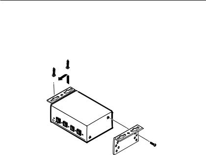
Furniture mounting
Furniture mount the MSW using the optional MBU 123 under-desk mounting kit (part #70-212-01) as follows:
1.If necessary, remove the feet from the bottom of the MSW.
2.Attach the mounting brackets to the MSW with the provided machine screws (see figure 5).
AUTO
SWITCH MODE
1
NORMAL
2
AUTO
3 |
|
|
A/V |
4 |
|
SWITCHER |
||
|
Figure 5 — Furniture mounting the MSW
3.Hold the MSW with the attached brackets against the underside of the table or other furniture. Mark the location of the screw holes of the bracket on the mounting surface.
4.Drill four 3/32 inch (2 mm) diameter pilot holes, 1/4 inch (6.3 mm) deep in the mounting surface at the marked screw locations.
5.Insert #8 wood screws into the four pilot holes. Tighten each screw into the mounting surface until just less than 1/4 inch of the screw head protrudes.
6.Align the mounting screws with the slots in the brackets and place the MSW against the surface, fitting the screws through the bracket slots.
7.Slide the switcher slightly forward or back, then tighten all four screws to secure the MSW in place.
5 MSW 4V rs and 4SV rs • Installation and Operation

Rear Panel Connections
1
MSW 4SV rs
|
|
I |
O |
POWER 1 |
3 |
N |
U |
P |
T |
||
12V |
|
U |
P |
.5A MAX |
|
T |
U |
|
|
S |
T |
|
|
|
S |
RS-232
2
Tx Rx
CONTACT
2 |
4 |
B |
1 |
2 |
3 |
4 |
7 |
5 |
4 |
3 |
MSW 4SV rs |
|
|
|
MSW 4V rs |
|
|
RS-232 |
|
|
|
I |
O |
|
|
|
2 |
|
|
|
N |
U |
|
Tx Rx |
|
|
POWER |
1 |
3 |
P |
T |
A |
|
|
|
U |
P |
|
|
|
||||
12V |
|
|
T |
U |
|
CONTACT |
||
.5A MAX |
|
|
S |
T |
|
|||
|
|
|
|
S |
|
|
|
|
|
2 |
4 |
|
|
B |
1 2 |
3 |
4 |
7 |
6 |
1 |
3 |
MSW 4V rs
Figure 6 — MSW 4SV rs and MSW 4V rs rear panel
NThe MSW switches during the vertical interval of input 1. For seamless switching, ensure one of the genlocked devices is connected to input 1.
aComposite video output(s) (both switcher models) — For each composite video output, connect a composite video display or other output device to this BNC connector.
NOutputs A and B output only one selected input signal.
NThe MSW 4SV has a built-in encoder; however, you can use both outputs simultaneously.
bRS-232 connector — Connect a cable with a 3.5 mm, 5-pole captive screw connector to this port for bidirectional RS-232 communication. Wire the connectors as shown on page 7.
MSW 4V rs and 4SV rs • Installation and Operation |
6 |
Installation and Operation, cont’d
Rear Panel RS-232 Port
Tx Rx  A S
A S
Connect a ground wire between the switcher and the computer or control system. If you use cable that has a drain wire, tie the drain wire to ground at both ends.
Green
Ground
Orange
Red
Rx Receive
Tx Transmit
|
5 |
1 |
9-pin HD |
|
|
Connector |
|
|
To Computer |
9 |
6 |
|
|
Figure 7 — RS-232 connector wiring
This port has the following RS-232 protocol:
•9600 baud
•1 stop bit
•No parity
•8 data bits
See “Using the command/response table” section on
page 15 for the Extron Simple Instruction Set (SIS) commands to communicate with the MSW switcher via RS-232.
c |
Contact connector — Connect a remote contact |
CONTACT |
|
||
|
closure device to the MSW for remote control of |
|
|
the switcher. You can also daisy chain the unit |
|
|
1 2 3 4 |
|
|
to other MSWs using this 5-pole captive screw |
|
connector. This allows remote control of the other switchers.
NThe switcher must be in normal (manual) mode for contact closure to work. See “Mode selection” on page 11.
To select an input using a contact closure device, such as an Extron CCR 204 Contact Closure Remote Control or a locally constructed device, momentarily short the pin for the desired input number to logic ground (pin 5). To force one of the inputs to be always selected, leave the short in place. The short overrides any front panel input selections.
You can also daisy chain multiple MSWs by using the contact connector. This allows for front panel control of all switchers (for example, touch the input button on one MSW to switch all MSWs). Wire pin 1 to pin 1, pin 2 to pin 2, and so on.
7 MSW 4V rs and 4SV rs • Installation and Operation
Loading...