

Extreme Networks X690-48t-2q-4c, X690-48x-2q-4c Quick Reference
X690 Series Switch Quick
Reference
Follow these steps to get your switch up and running.
For complete installation instructions see the ExtremeSwitching and
Summit Switches: Hardware Installation Guide at
www.extremenetworks.com/documentation
Tools You’ll Need
• Appropriate grounded power receptacles
located within 1.8 m (6 ft.)
• A readily accessible device for disconnecting
power, such as a breaker or master switch
• Network cabling within reach
• At least of 7.6 cm (3.0 in.) on all sides, for
proper ventilation
• Temperature between 0°C (32°F) and 45°C
(113°F) with fluctuations of less than 10°C
(18°F) per hour
If the switch appears to be damaged, contact Extreme Networks. See
“Getting Help” for more information.
Extreme Networks does not include power input cords with this product.
To purchase the correct power cord for your country, refer to
www.extremenetworks.com/product/powercords/. This page lists
details for purchasing a power cord from Extreme Networks or from
your local supplier.
1 #1 Phillips screwdriver
(magnetic screwdriver recommended)
3 Rack-mounting screws
2 Flat-head screwdriver 4 ESD-protective wrist strap
1
Prepare the Site
The installation site must meet the following requirements:
2
Unpack the Box
Remove the packing material. Break the tape seal on the
non-conductive bag and remove the switch.
1 Switch (48-port model shown) 3 Bracket screws
2 Mounting brackets
There are four ways to mount the X690 Series switch in a rack:
• Either the I/O ports or the power-supply side can face front.
• The switch can be mounted flush with the rack posts or midmounted.
1 Attach the mounting brackets to the sides of the switch using six
screws (included) for each bracket.
2 Align the holes in the brackets with the rack post holes.
3 Secure the switch to each post with fasteners appropriate to the rack.
1
1 Attach the ESD wrist strap to your wrist and connect the metal end
to an appropriate ground point on the rack.
2 Remove the transceiver from its packaging.
3 If applicable, remove the protective dust cover from the connector.
4 Hold the transceiver so that the connector will seat properly.
5 Carefully align the transceiver with the port slot.
6 Push the transceiver into the port slot until it clicks into place.
3
Install the Switch
You can install any X690 Series switch in a standard 19inch equipment rack.
4
Install Transceivers
(Optional) Transceivers can send and receive data over
optical fiber rather than through electrical wires. This
installation procedure applies to all transceivers.
Note: Transceivers are Class 1 or Class 1M laser devices.
Connecting to the Primary Power Source
To attach your X690 Series switch to a power source, do the following:
1 Connect the AC power cord to the AC power input socket on the
power supply and an AC power outlet.
2 For DC powered supplies, verify that the DC circuit is de-energized
and then do the following:
a Identify the grounding stud on the DC power supply. The grounding
stud is next to the DC input connector, identified by the international
symbol for earth ground.
b Using the nut and washer provided, connect the ring terminal end of
the ground wire to the grounding stud on the DC power supply.
Use green and yellow stranded copper wire, sized at least 14 AWG.
c Connect the other end of the ground wire to a reliable earth ground.
d Connect the DC power input cables to the DC input connector
provided.
Use copper wires rated for at least 60°C and sized between 14 AWG
and 8 AWG.
e Energize the circuit.
3 When power is connected, verify that the switch’s PWR LED turns
green. If the PWR LED does not turn green, refer to the Hardware
Installation Guide for troubleshooting information.
Safety Notices
5
Connect Power
X690 Series switches can run on AC or DC power. Connect
the switch to a primary power source.
Note: Installing the system as described in this guide meets the
protective earth grounding requirements of the National Electrical
Code (NEC) UL 60950 and IEC 60950 standards. However, in some
cases, it may be necessary to use an alternative grounding method.
In these cases, a 14 AWG wire can be connected between the
grounding lug on the chassis and a nearby building ground point.
6
Configure the Switch
To connect the switch to the network and configure it for
use, follow the steps in www.extrconfig.com/exos.
Electrical Hazard: Only qualified personnel should perform
installation procedures.
Risques d’électrocution: Seul un personnel qualifié doit effectuer
les procédures d'installation.
Warning: Extreme Networks power supplies do not have switches for turning
the unit on and off. Before servicing, disconnect all power cords to remove
power from the device. Make sure that these connections are easily accessible.
Avertissement: Extreme Networks alimentations ne sont pas des interrupteurs
pour allumer l'appareil et en dehors. Avant l'entretien, débranchez tous les
cordons d'alimentation pour couper l'alimentation de l'appareil. Assurez-vous
que ces connexions sont facilement accessibles.
Warning: A dedicated Listed circuit breaker rated at 15A is to be used for each
power supply connection.
Avertissement: Un disjoncteur cotée dédiée évalué à 15A doit être utilisée pour
chaque connexion d'alimentation.
Caution: Before mounting the device, ensure that the rack can support it
without compromising stability. Otherwise, personal injury and/or equipment
damage may result.
Caution: Follow appropriate ESD procedures when unpacking and handling
the switch. These include unpacking the switch in an ESD-safe environment
and wearing appropriate ESD protective gear, such as ESD-safe footwear and
ESD wrist straps where appropriate.
Caution: Use of controls or adjustments or performance of procedures other
than those specified herein may result in hazardous radiation exposure.
Warning: Do not use optical instruments to view the laser output. The use of
optical instruments to view laser output increases eye hazard. Use only
UL/CSA, IEC/EN60825-1/-2 recognized pluggable modules.
Avertissement: Ne pas utiliser d'instruments optiques pour voir la sortie du
laser. L'utilisation de instruments optiques pour afficher la sortie laser
augmente les risques oculaires. Utilisez uniquement UL/CSA,
IEC/EN60825-1 /-2 reconnu modules enfichables.
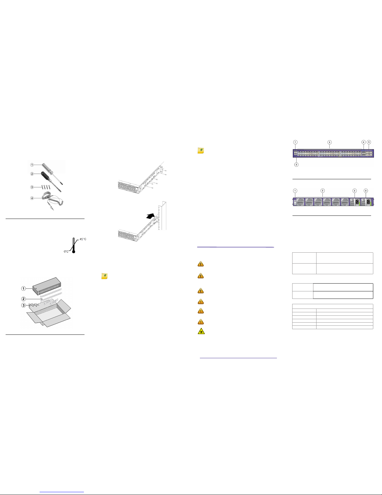
Hardware Components
Figure 1 X690 Series Switch: Front Panel
Figure 2 X690 Series Switch: Rear Panel
For component details, see the Hardware Installation Guide.
Operating Conditions
Operating Temperature:
0°C (32°F) to 45°C (113°F)
Storage Temperature:
-40°C to 70°C (-40°F to 158°F)
Operating Relative Humidity:
5% to 95% (non-condensing)
Interfaces
Each X690 Series switch has a management port, a console port, and a
USB port. The following table lists the specific interfaces for each switch.
Power Specifications
Power Supply and Fan Options
1 Console/management port 4 10Gb/40Gb QSFP+ ports
2 USB port 5
10Gb/25Gb/40Gb/50Gb/100Gb
capable
QSFP28 ports
3 1Gb/10GBASE-T ports (48t model) or
1Gb/10Gb SFP+ ports (48x model)
1
Grounding lug 3 DC power input connector
2
Fan modules
X690-48t-2q-4c
(Part no. 17360)
X690 base unit with 48 1Gb/10GBASE-T ports, 2 10Gb/
40Gb QSFP+ ports, 4 10Gb/25Gb/40Gb/50Gb/100Gb
capable QSFP28 ports, 2 unpopulated power supply
slots, 6 unpopulated fan module slots, ExtremeXOS
Advanced Edge License
X690-48x-2q-4c
(Part no. 17350)
X690 base unit with 48 1Gb/10Gb SFP+ ports, 2 10Gb/
40Gb QSFP+ ports, 4 10Gb/25Gb/40Gb/50Gb/100Gb
capable QSFP28 ports, 2 unpopulated power supply
slots, 6 unpopulated fan module slots, ExtremeXOS
Advanced Edge License
X690-48t-2q-4c
(Part no. 17360)
AC Input: 100-127VAC, 4.0A max. 50-60Hz for each PSU
AC Input: 200-240VAC, 2.0A max. 50-60Hz for each PSU
DC Input: -48 to -60VDC, 8.0A max. for each PSU
X690-48x-2q-4c
(Part no.17350)
AC Input: 100-127VAC, 3.0A max. 50-60Hz for each PSU
AC Input: 200-240VAC, 1.5A max. 50-60Hz for each PSU
DC Input: -48 to -60VDC, 6.0A max. for each PSU
X690-48t-2q-4c
X690-48x-2q-4c
Part no. 10960 770W AC power supply, Front-to-Back airflow
Part no. 10961 770W AC power supply, Back-to-Front airflow
Part no. 10962 1100W DC power supply, Front-to-Back airflow
Part no. 10963 1100W DC power supply, Back-to-Front airflow
Part no. 17115 X870 Fan Module, Front-to-Back airflow
Part no. 17116 X870 Fan Module, Back-to-Front airflow
Getting Help
For additional support related to X690 Series switches or this document,
contact Extreme Networks using one of the following methods:
Notice
Copyright © 2017 Extreme Networks, Inc. All Rights Reserved.
Legal Notices
Extreme Networks, Inc. reserves the right to make changes in specifications
and other information contained in this document and its website without
prior notice. The reader should in all cases consult representatives of
Extreme Networks to determine whether any such changes have been
made.
The hardware, firmware, software or any specifications described or referred
to in this document are subject to change without notice.
Trademarks
Extreme Networks and the Extreme Networks logo are trademarks or
registered trademarks of Extreme Networks, Inc. in the United States and/or
other countries.
All other names (including any product names) mentioned in this document
are the property of their respective owners and may be trademarks or
registered trademarks of their respective companies/owners.
For additional information on Extreme Networks trademarks, please see:
www.extremenetworks.com/company/legal/trademarks/
Warranty
Warranty information for X690 Series series switches is located online at:
www.extremenetworks.com/support/policies/
Regulatory and Compliance Information
Federal Communications Commission (FCC) Notice
This device complies with Part 15 of the FCC rules. Operation is subject to
the following two conditions: (1) this device may not cause harmful
interference, and (2) this device must accept any interference received,
including interference that may cause undesired operation.
NOTE: This equipment has been tested and found to comply with the limits
for a class A digital device, pursuant to Part 15 of the FCC rules. These limits
are designed to provide reasonable protection against harmful interference
when the equipment is operated in a commercial environment. This
equipment uses, generates, and can radiate radio frequency energy and if
not installed in accordance with the operator’s manual, may cause harmful
interference to radio communications. Operation of this equipment in a
residential area is likely to cause interference in which case the user will be
required to correct the interference at his own expense.
WARNING: Changes or modifications made to this device which are not
expressly approved by the party responsible for compliance could void the
user’s authority to operate the equipment.
Industry Canada Notice
CAN ICES-3 (A)/NMB-3(A)
This digital apparatus does not exceed the class A limits for radio noise
emissions from digital apparatus set out in the Radio Interference
Regulations of the Canadian Department of Communications.
Le présent appareil numérique n’émet pas de bruits radioélectriques
dépassant les limites applicables aux appareils numériques de la class A
prescrites dans le Règlement sur le brouillage radioélectrique édicté par le
ministère des Communications du Canada.
Class A ITE Notice
WARNING: This equipment is compliant with Class A of CISPR 32. In a
residential environment this equipment may cause radio interference.
Product
Documentation
https://www.extremenetworks.com/documentation/
Global Technical
Assistance Center
(GTAC)
Phone: 1-800-998-2408 (toll-free in U.S. and Canada)
or +1-408-579-2826. For the support phone number in
your country, visit:
http://www.extremenetworks.com/support/contact/
GTAC Knowledge
Get on-demand and tested resolutions from the GTAC
Knowledgebase, or create a help case if you need more
guidance.
Visit: https://gtacknowledge.extremenetworks.com/
The Hub
A forum for Extreme customers to connect with one
another, get questions answered, share ideas and
feedback, and get problems solved. The community is
monitored by Extreme Networks employees, but is not
intended to replace specific guidance from GTAC.
Visit: https://community.extremenetworks.com
Support Portal
Manage cases, downloads, service contracts, product
licensing, and training and certifications.
Visit: http://support.extremenetworks.com/
Product Safety
This product complies with the following international safety standards:
• UL 60950-1 2nd edition, A2:2014
• CAN/CSA-C22.2 No.60950-1-07 2nd Ed. 2014-10
• IEC 60950-1:2005 2nd+A1:2009+A2:2013
• EN 60950-1:2006+A11+A1+A12+A2
• 2014/35/EU
• CNS 14336-1
Optical Module Compliance
Extreme Networks pluggable optical modules and direct-attach cables meet
the following regulatory requirements:
• UL and/or CSA registered component for North America
• Class 1 or Class 1M Laser Product
• FCC 21 CFR Chapter 1, Sub-chapter J in accordance with FDA & CDRH
requirements
• IEC/EN 60825-1:2007, IEC/EN 60825-2:2004+A1+A2 or later, European
Standard
Korea EMC Statement
Australia (RCM)
WARNING: This equipment is compliant with Class A of CISPR 32. In a
residential environment this equipment may cause radio interference.
Electromagnetic Compatibility (EMC)
This product complies with the following: FCC 47 CFR Part 15 Subpart B
Class A (US), ICES-003 (Canada), EN 55032 (ITE Emissions), EN 55024 (ITE
Immunity), EN 61000-3-2 (Harmonics), EN 61000-3-3 (Flicker), 2014/30/EU
(EMC Directive), EN 300 386 (Telecom), EN 55011 (ISM), EN 61000-6-2 (Ind.
Immunity), EN 61000-6-4 (Ind. Emissions), RCM (Australia), VCCI (Japan),
MSIP KCC (Korea), BSMI (Taiwan), ANATEL (Brazil), CCC (China).
VCCI Notice
This is a Class A product based on the standard of the Voluntary Control
Council for Interference by Information Technology Equipment (VCCI). If this
equipment is used in a domestic environment, radio disturbance may arise.
When such trouble occurs, the user may be required to take corrective
actions.
BSMI EMC Statement — Taiwan
This is a Class A product. In a domestic environment this product may cause
radio interference in which case the user may be required to take adequate
measures.
Warning: The X690 switch may be hot to the touch during normal
operation.
Attention: Le X690 peut être chaude au toucher pendant le
fonctionnement normal.
Warning: The X690 switch is designed for installation in restricted
access locations.
Attention: Le X690 est conçus pour une installation dans des
endroits à accès restreint.
Battery Warning — Taiwan
Hazardous Substances - EU
This product complies with the requirements of Directive 2011/65/EU of the
European Parliament and of the Council of 8 June 2011 on the restriction of
the use of certain hazardous substances in electrical and electronic
equipment.
European Waste Electrical and Electronic Equipment (WEEE)
Notice
In accordance with Directive 2012/19/EU of the European Parliament on
waste electrical and electronic equipment (WEEE):
1 The symbol above indicates that separate collection of electrical and
electronic equipment is required.
2 When this product has reached the end of its serviceable life, it cannot be
disposed of as unsorted municipal waste. It must be collected and treated
separately.
3 It has been determined by the European Parliament that there are
potential negative effects on the environment and human health as a
result of the presence of hazardous substances in electrical and electronic
equipment.
4 It is the users’ responsibility to utilize the available collection system to
ensure WEEE is properly treated.
For information about the available collection system, please contact
Extreme Customer Support at +353 61 705500 (Ireland).
Battery Notice
Warning: This product contains a battery used to maintain product
information. If the battery should need replacement it must be
replaced by Service Personnel. Please contact Technical Support for
assistance.
Risk
of explosion if battery is replaced by an incorrect type. Dispose
of expended battery in accordance with local disposal regulations.
Avertissement: Ce produit renferme une pile servant à conserver les
renseignements sur le produit. Le cas échéant, faites remplacer la
pile par le personnel du service de réparation. Veuillez communiquer
avec l’assistance technique pour du soutien.
Il y a risque d’explosion si la pile est remplacée par un type de pile
incorrect. Éliminez les piles usées en conformité aux règlements
locaux d'élimination des piles.
Extreme Networks
ExtremeSwitching
X690 Series Switches
Quick Reference
X690-48t-2q-4c
X690-48x-2q-4c
P/N 121148-00
Hazardous Substances- China and Taiwan BSMI RoHS
Guidance concerning the China and Taiwan BSMI RoHS (Restriction of
Hazardous Substances) directive for this Extreme Networks® product can be
found on the following web page:
www.extremenetworks.com/support/documentation/restriction-hazardoussubstances/
The page contains tables detailing the presence of 10 substances defined by
the RoHS directive.
 Loading...