

Extreme Networks WM-4T1i WAN, WM-4E1i WAN, WM-1T3i WAN Installation And User Manual

WAN Module Installation
and User Guide
(Includes WM-4T1i Module Installation and User Guide)
Extreme Networks, Inc.
3585 Monr oe Street
Santa Clara, California 95051
(888) 257-3000
http://www.extremenetworks.com
Published: December, 2001
Part number:100 095-00 rev0 2

©2001 Extreme Networks, Inc. All rights reserved. Extreme Networks and BlackDiamond are
registered trademarks of Extreme Networks, Inc. in the United States and certain other jurisdictions.
ExtremeWare, ExtremeWare Vista, ExtremeWorks, ExtremeAssist, ExtremeAssist1, ExtremeAssist2,
PartnerAssist, Extreme Standby Router Protocol, ESRP, SmartTraps, Alpine, Summit, Summit1,
Summit4, Summit4/FX, Summit7i, Summit24, Summit48, Summit Virtual Chassis, SummitLink,
SummitGbX, SummitRPS, and the Extreme Networks logo are trademarks of Extreme Networks, Inc.,
which may be registered or pending registration in certain jurisdictions. The Extreme Turbodrive logo
is a service mark of Extreme Networks, which may be registered or pending registration in certain
jurisdictions. Specifications are subject to change without notice.
All other registered trademarks, trademarks, and service marks are property of their respective owners.
ii

Contents
Preface
Introduction -v
Terminology -vi
Conventions -vi
Related Publications -viii
1 Installing the WAN Module
Overview 1-1
Installing the WAN Module 1-2
Ports and Connectors 1-3
Module LEDs 1-4
Installing the WAN Module Software 1-6
2 Configuring the WAN Physical Link
Overview 2-1
Red, Blue, and Yellow Alarms 2-2
Configuring WAN Physical Links 2-2
Cable length 2-3
Clock Source 2-4
Facility Data Link 2-4
Framing 2-4
Inband Loopback Detection 2-5
WAN Module Installation and User Gu ide iii

Linecoding 2-5
Receiver Gain 2-5
SNMP Alerts 2-5
Timeslots 2-6
Yellow Alarms 2-6
WAN Port Configuration Commands 2-7
Monitoring WAN Physical Links 2-8
Loopback 2-8
Near-end Loopback Modes 2-9
Far-End Loopback Modes 2-11
Enabling Loopback Mode 2-12
Disabling Loopback Mode 2-12
WAN Port Monitoring Commands 2-13
3 Configuring PPP and MLPPP
Overview 3-1
Multilink PPP and Multilink Groups 3-2
Configuring a PPP/MLPP P Link 3-3
Authentication 3-3
PPP Link Userna me 3-4
PPP User Accounts 3-4
Encapsulation 3-4
PPP/MLPPP Configuration Commands 3-5
Monitoring PPP/MLPPP Links 3-6
PPP/MLPPP Configuration Examples 3-7
Configuring a Bridged PP P/MLPPP Link Example 3-7
Configuring a Routed PPP/ MLPPP Link Example 3-8
Industry Canada Certificat ion A-1
FCC Certification A-2
Index
Index of Commands
iv WAN Module Installation and User Guide

Preface
This Preface provides an overview of this guide, describes guide conventions, and lists
other publications that may be useful.
Introduction
This guide provides the required information to in stall the WM-4T1i, WM-4E1i, and
WM-1T3i WAN modules in an Alpine 3800 series switch from Extreme Networks and
perform the initial module conf iguration tasks.
This guide is intended for use by network administrators who are responsible for
installing and setting up n etwork equipment. It assumes a ba sic working knowledge of:
• Local area networks (LANs).
• Ethern et conc epts.
• Ethernet switching and bridging concepts.
• Routing concepts .
• Internet Protocol (IP) co ncepts.
• Routing Information Protocol (RIP) and Open Shortest Path First (OSPF).
• Simple Network Managemen t Protocol (SNMP).
If the information i n the release notes shipp ed with your module diffe rs from the
information in this guide, follow the release no tes.
WAN Module Installation and User Gu ide v

Terminology
When features, functionality, or operation is specific to o ne of the WAN modules, the
specific module name is used. E xplanations about feat ures and operations that are the
same for both of the WAN modules simply refer to the product as the “module.”
Conventions
Table1 and Table 2 list conventions that are used throughout this guide.
Table 1: Notice Icons
Icon Notice Type Alerts you to...
Note Important features or instructions.
Caution Risk of personal injury, system damage, or loss of data.
Warning Risk of severe personal inju ry.
Table 2: Text C onventions
Convention Description
Screen displays This typeface indicates command syntax, or represents information
as it appears on the screen.
Screen displays
bold
The words “enter”
and “type”
[Key] names Key names are written with brackets, such as [Return] or [Esc].
This typeface indicates how you would type a particular command.
When you see the word “enter” in this guide, you must type
something, and then press the Return or Enter key. Do not press the
Return or Ente r key when an inst ruction simp ly says “type .”
If you must press two or more keys simultaneously, the key names
are linked with a plus sign (+). Example:
Press [Ctrl]+[Alt]+[Del].
vi WAN Module Installation and User Guide

Conventions
Table 2: Te xt Conventions (conti nued)
Convention Description
Words in italicized type Italics emphasize a point or denote new terms at the place where
they are defined in the text.
WAN Module Installation and User Gu ide vii

Related Publications
The publications related to this one are:
• ExtremeWare
• ExtremeWare Software User Guide
• Alpine 3800 Series S witch Hardware Installation Gu ide
• Alpine Module Installation Note
Documentation for Extreme Networks products is available on the World Wide Web at
the following location :
http://www.extremenetworks.com/
™
release n otes
viii WAN Module Installation and User Guide

1
Installing the WAN Module
This chapter covers the followin g topics:
• Installing the WAN Module on page 1-2
• Ports and Connectors on pa ge 1-3
• Module LEDs on page 1-4
• Installing the WAN Module Software on page 1-6
Overview
The Extreme Networks WAN m odules include four-port T1 or E1 modules that can be
configured to use Multilink PPP t o aggregate Ethernet or IP routed traffic across
multiple T1/E1 physical l inks. The modules also have two general purpose 10/100
Mbps Ethernet ports. WM-4T1i is the designatio n of the T1 version, and WM-4E1i is th e
designation of the E1 version. Also included among the WAN modules is a one-port T3
module, designated WM-1T3i, that uses PPP for its traffic.
The modules also have eight internal loopback po rts. The Alpine 3800 switch m odules
have hardware queues associated with the output of each port for QoS (rate shaping
and priority queueing). To implement ingress QoS, you needed to use the hardware
queues associated with a second port as a loopback port for ingress QoS.
WAN Module Installation and User Gu ide 1-1
Installing the WAN Module
Installing the WAN Module
All Alpine ™ 3800 series switch module cards (SMMi modules and I/O modules) are
hot-swappable. You do not need to power off the system to remove or insert a module
card.
Caution: Servic e to Alpine modules sh ould be performed by tr ained service
personnel only. Before installing or removing any co mponents of the syst em, or
before carrying out any maintenance proce dures, read the safety inf ormation
provided in Appendix A of the Alpine Hardware Installation Guide.
Warning: You must install blank panel s in empty slots to ens ure adequa te system
cooling.
To remove and replace a module card, follow these steps:
1 Prior to removing/installing a module card into the Alpine 3804 or Alpine 380 8
chassis, put on the ESD wrist strap that is provided with the chassis, and connect the
metal end to the ground receptacle located on the top-right corner of the Alpine
front panel.
2 Loosen the module card by unscrewing the screws usin g a #2 Phillips-head
screwdriver.
3 Rotate the ejector/injector handles t o disengage the module card from the backplane.
Note: Blank pan els do not have ejector/ injector handles, be cause they do not
engage the backpl ane. They are secured e ntirely by the retain ing screws. In
addition, the retaini ng screws are not cap tive.
4 Slide the module card out of the chassis.
5 Slide the new module card into the appropriate slot of the chassis (SMMi modules
into the orange slot, I/O m odules into Slots 1 through 4 o n the Alpine 3804, or Slots
1 through 8 on the Alpine 3808), until i t is fully seated in the backplan e.
Caution: Ensure t hat the sheet metal of the m odule, and not the PCB bo ard,
engages the ca rd cage runners.
As the module begins to seat in th e chassis, the ejector/ injector handles will begin to
close.
6 To secure the module in the chassis, clos e the ejector/injector han dles by pushing
them toward the center of the module card, and tighten the screws using a #2
Phillips-head screwdriver.
1-2 WAN Module Installation and U ser Guide
Note: Tighten the s crews before insertin g additional modu les. If you insert
additional modul es before tightening the screws, you might unseat modules
that you have not se cured.
Caution: You can only install I/O modules in the slots l abeled Slot 1 throug h
Slot 4 o n the Alpine 3804, or Slot 1 through Slot 8 on the Alpin e 3808. Forceful
insertion can dama ge the I/O module and the co nnector pins on the b ackplane.
Ports and Connectors
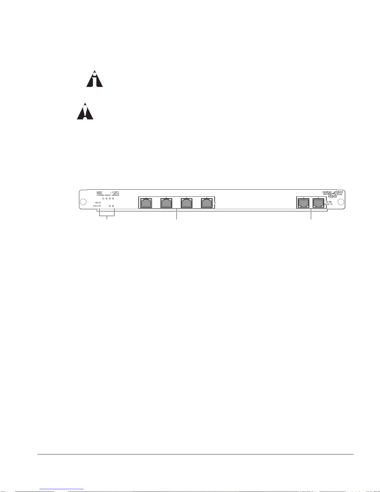
The WM-4T1i module is shown in Figure 1-1.
Ports and Conne ctors
Module status
LEDs
T1 ports 10/100 Mbps ports
38_WM4T1i
Figure 1-1: WM-4T1i Module
The WM-4T1i module has four T1 ports and two general purpose 10/100 Ethernet
ports. The WM-4T1i also has eigh t internal loopback ports. Intern al loopback ports
allow you to configure bi-directional rate-limiting without tying up any of the externa l
ports for ingress rate shaping. Internal loopback ports are marked with the notatio n
“iL” when displayed on the command line or with ExtremeWare Vista Web access.
The WM-4E1i module has fou r E1 ports in place of the T1 po rts found in the WM-4T1i
module. It is identical in all o ther respects.
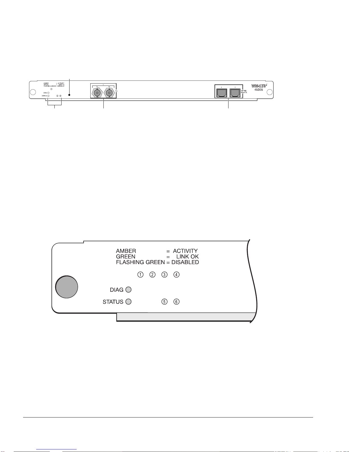
The WM-1T3i module is shown in Figure 1-2.
WAN Module Installation and User Gu ide 1-3
Installing the WAN Module
Module reset
T3 port
LEDs
10/100 Mbps portsModule status
38_WM1T3i
Figure 1-2: WM-1T3i Module
The WM-1T3i module has one T3 port, consistin g of a two BNC connectors, one fo r the
transmit path and one for the receive path. The module also has two general purpo se
10/100 Ethernet ports. L ike the other WAN modules, the WM-1T3i also has eight
internal loopback ports.
Module LEDs
The T1/E1 module LEDs are shown in Figure 1-3. The WM-1T3i module LEDs are
similar, but there is only one WAN port LED and the Ethernet port LEDs are numbered
2 and 3.
Figure 1-3: T1/E1 Module LEDs
1-4 WAN Module Installation and U ser Guide

Table 1-1 describes the LED behavior on the WAN modules.
Table 1-1: WAN Module LEDs
LED Color Indicates
Status Off No power
Amber Module seated in chassis
Green Module powered up
Diag Green (blinking) Power-on Self Test (POST) is running
Off Normal operation
WAN port
(1-4)T1/E1
(1)T3
10/100 por t
(5,6)T1/E1
(2,3)T3
Amber Near-end f ault det ected (for example, no cable )
Amber (blinking
Far-end f ault detec ted
rapidly)
Amber (blinking
slowly)
Physical link present, but no higher-layer link
established
Green Physical link present, higher-layer link established,
no traffic
Alternating green
and amber
Green (blinking
Physical link present, higher-layer link established,
traffic present
Port disabled or unconfigured
slowly)
Green (blinking
Loopback testing mode
rapidly)
Off No link pr esent
Green Link present
Alternating green
Traffic p resent
and amber
Ports and Conne ctors
The slowly blinking LEDs cycle once per second. The rapidly blinking LEDs cycle twice
a second.
WAN Module Installation and User Gu ide 1-5

Installing the WAN Module
Installing the WAN Module Software
Once the WAN module is installed in the chas sis, you might need to update the i mage
file on the module. See the release notes for your version of ExtremeWare for details.
(You might also need to update the image on the SMMi to o ne that will support the
module. See the ExtremeWare Software User Guide for more information on updating th e
SMMi image.)
The image file contains the executable code that runs on the module. As new versions
of the image are released, you should upgrade the s oftware running on your module.
The image installed on the SMMi and the image installed on the module must be
compatible. New SMMi images and module images are released together, so if you
upgrade both at the same time, y ou will be certain to have compat ible images. If this is
not feasible, see the Extreme Networks customer support website for compatibility
information.
The image is downloaded from either a Trivial File Tra nsfer Protocol (TFTP) server on
the network or from a PC connected to the serial port us ing the XMODEM protocol.
Downloading a new i mage involves the followin g steps:
• Load the new image onto a TFTP server on your network (if you will be us ing
TFTP).
• Load a new image on to a PC (if you will be using XMODEM).
• Download the new image to the module using the command
download image slot <slot> [<ipaddress> | <hostname>] <filename>
{primary | secondary}
where the following is true:
slot — Is the slot in which the module is installed.
ipaddress — Is the IP address of the TFTP server.
hostname — Is the hostname of the TFTP server. (You must enable DNS to use this
option. See the ExtremeWare Software User Guide for more information.)
filename — Is the filename of the new image.
primary — Indicates the primary image.
secondary — Indicates the secondary image.
1-6 WAN Module Installation and U ser Guide
 Loading...