


Installing the Virtual Services Platform
8600
Release 6.2 (VSP 8600)
9035590
September 2018

©
2018, Extreme Networks, Inc.
All Rights Reserved.
Notice
While reasonable efforts have been made to ensure that the
information in this document is complete and accurate at the time of
printing, Extreme Networks, Inc. assumes no liability for any errors.
Extreme Networks, Inc. reserves the right to make changes and
corrections to the information in this document without the obligation
to notify any person or organization of such changes.
Documentation disclaimer
“Documentation” means information published in varying mediums
which may include product information, operating instructions and
performance specifications that are generally made available to users
of products. Documentation does not include marketing materials.
Extreme Networks shall not be responsible for any modifications,
additions, or deletions to the original published version of
Documentation unless such modifications, additions, or deletions
were performed by or on the express behalf of Extreme Networks.
End User agrees to indemnify and hold harmless Extreme Networks,
Extreme Networks’ agents, servants and employees against all
claims, lawsuits, demands and judgments arising out of, or in
connection with, subsequent modifications, additions or deletions to
this documentation, to the extent made by End User.
Link disclaimer
Extreme Networks is not responsible for the contents or reliability of
any linked websites referenced within this site or Documentation
provided by Extreme Networks. Extreme Networks is not responsible
for the accuracy of any information, statement or content provided on
these sites and does not necessarily endorse the products, services,
or information described or offered within them. Extreme Networks
does not guarantee that these links will work all the time and has no
control over the availability of the linked pages.
Warranty
Extreme Networks provides a limited warranty on Extreme Networks
hardware and software. Refer to your sales agreement to establish
the terms of the limited warranty. In addition, Extreme Networks’
standard warranty language, as well as information regarding support
for this product while under warranty is available to Extreme
Networks customers and other parties through the Extreme Networks
Support website:
www.extremenetworks.com/support/ under the link
““Policies” or such successor site as designated by Extreme
Networks. Please note that if You acquired the product(s) from an
authorized Extreme Networks Channel Partner outside of the United
States and Canada, the warranty is provided to You by said Extreme
Networks Channel Partner and not by Extreme Networks.
“Hosted Service” means an Extreme Networks hosted service
subscription that You acquire from either Extreme Networks or an
authorized Extreme Networks Channel Partner (as applicable) and
which is described further in Hosted SAS or other service description
documentation regarding the applicable hosted service. If You
purchase a Hosted Service subscription, the foregoing limited
warranty may not apply but You may be entitled to support services
in connection with the Hosted Service as described further in your
service description documents for the applicable Hosted Service.
Contact Extreme Networks or Extreme Networks Channel Partner (as
applicable) for more information.
Hosted Service
THE FOLLOWING APPLIES ONLY IF YOU PURCHASE AN
EXTREME NETWORKS HOSTED SERVICE SUBSCRIPTION
FROM EXTREME NETWORKS OR AN EXTREME NETWORKS
CHANNEL PARTNER (AS APPLICABLE), THE TERMS OF USE
FOR HOSTED SERVICES ARE AVAILABLE ON THE EXTREME
NETWORKS WEBSITE,
https://extremeportal.force.com/ OR SUCH
SUCCESSOR SITE AS DESIGNATED BY EXTREME NETWORKS,
AND ARE APPLICABLE TO ANYONE WHO ACCESSES OR USES
THE HOSTED SERVICE. BY ACCESSING OR USING THE
HOSTED SERVICE, OR AUTHORIZING OTHERS TO DO SO, YOU,
ON BEHALF OF YOURSELF AND THE ENTITY FOR WHOM YOU
ARE DOING SO (HEREINAFTER REFERRED TO
INTERCHANGEABLY AS “YOU” AND “END USER”), AGREE TO
THE TERMS OF USE. IF YOU ARE ACCEPTING THE TERMS OF
USE ON BEHALF A COMPANY OR OTHER LEGAL ENTITY, YOU
REPRESENT THAT YOU HAVE THE AUTHORITY TO BIND SUCH
ENTITY TO THESE TERMS OF USE. IF YOU DO NOT HAVE SUCH
AUTHORITY, OR IF YOU DO NOT WISH TO ACCEPT THESE
TERMS OF USE, YOU MUST NOT ACCESS OR USE THE
HOSTED SERVICE OR AUTHORIZE ANYONE TO ACCESS OR
USE THE HOSTED SERVICE.
Licenses
THE SOFTWARE LICENSE TERMS AVAILABLE ON THE
EXTREME NETWORKS WEBSITE,
https://extremeportal.force.com/
OR SUCH SUCCESSOR SITE AS DESIGNATED BY EXTREME
NETWORKS, ARE APPLICABLE TO ANYONE WHO
DOWNLOADS, USES AND/OR INSTALLS EXTREME NETWORKS
SOFTWARE, PURCHASED FROM EXTREME NETWORKS, INC.,
ANY EXTREME NETWORKS AFFILIATE, OR AN EXTREME
NETWORKS CHANNEL PARTNER (AS APPLICABLE) UNDER A
COMMERCIAL AGREEMENT WITH EXTREME NETWORKS OR
AN EXTREME NETWORKS CHANNEL PARTNER. UNLESS
OTHERWISE AGREED TO BY EXTREME NETWORKS IN
WRITING, EXTREME NETWORKS DOES NOT EXTEND THIS
LICENSE IF THE SOFTWARE WAS OBTAINED FROM ANYONE
OTHER THAN EXTREME NETWORKS, AN EXTREME
NETWORKS AFFILIATE OR AN EXTREME NETWORKS CHANNEL
PARTNER; EXTREME NETWORKS RESERVES THE RIGHT TO
TAKE LEGAL ACTION AGAINST YOU AND ANYONE ELSE USING
OR SELLING THE SOFTWARE WITHOUT A LICENSE. BY
INSTALLING, DOWNLOADING OR USING THE SOFTWARE, OR
AUTHORIZING OTHERS TO DO SO, YOU, ON BEHALF OF
YOURSELF AND THE ENTITY FOR WHOM YOU ARE
INSTALLING, DOWNLOADING OR USING THE SOFTWARE
(HEREINAFTER REFERRED TO INTERCHANGEABLY AS “YOU”
AND “END USER”), AGREE TO THESE TERMS AND CONDITIONS
AND CREATE A BINDING CONTRACT BETWEEN YOU AND
EXTREME NETWORKS, INC. OR THE APPLICABLE EXTREME
NETWORKS AFFILIATE (“EXTREME NETWORKS”).
Extreme Networks grants You a license within the scope of the
license types described below. Where the order documentation does
not expressly identify a license type, the applicable license will be a
Designated System License as set forth below in the Designated
System(s) License (DS) section as applicable. The applicable
number of licenses and units of capacity for which the license is
granted will be one (1), unless a different number of licenses or units
of capacity is specified in the documentation or other materials
available to You. “Software” means computer programs in object
code, provided by Extreme Networks or an Extreme Networks
Channel Partner, whether as stand-alone products, pre-installed on
hardware products, and any upgrades, updates, patches, bug fixes,
or modified versions thereto. “Designated Processor” means a single
stand-alone computing device. “Server” means a set of Designated
Processors that hosts (physically or virtually) a software application
to be accessed by multiple users. “Instance” means a single copy of
the Software executing at a particular time: (i) on one physical
machine; or (ii) on one deployed software virtual machine (“VM”) or
similar deployment.
License type(s)
Designated System(s) License (DS). End User may install and use
each copy or an Instance of the Software only: 1) on a number of
Designated Processors up to the number indicated in the order; or 2)
up to the number of Instances of the Software as indicated in the
order, Documentation, or as authorized by Extreme Networks in
writing. Extreme Networks may require the Designated Processor(s)
to be identified in the order by type, serial number, feature key,
Instance, location or other specific designation, or to be provided by
End User to Extreme Networks through electronic means established
by Extreme Networks specifically for this purpose.
Copyright
Except where expressly stated otherwise, no use should be made of
materials on this site, the Documentation, Software, Hosted Service,
or hardware provided by Extreme Networks. All content on this site,
the documentation, Hosted Service, and the product provided by
Extreme Networks including the selection, arrangement and design
of the content is owned either by Extreme Networks or its licensors
and is protected by copyright and other intellectual property laws
including the sui generis rights relating to the protection of databases.
You may not modify, copy, reproduce, republish, upload, post,
transmit or distribute in any way any content, in whole or in part,

including any code and software unless expressly authorized by
Extreme Networks. Unauthorized reproduction, transmission,
dissemination, storage, and or use without the express written
consent of Extreme Networks can be a criminal, as well as a civil
offense under the applicable law.
Virtualization
The following applies if the product is deployed on a virtual machine.
Each product has its own ordering code and license types. Note,
unless otherwise stated, that each Instance of a product must be
separately licensed and ordered. For example, if the end user
customer or Extreme Networks Channel Partner would like to install
two Instances of the same type of products, then two products of that
type must be ordered.
Third Party Components
“Third Party Components” mean certain software programs or
portions thereof included in the Software or Hosted Service may
contain software (including open source software) distributed under
third party agreements (“Third Party Components”), which contain
terms regarding the rights to use certain portions of the Software
(“Third Party Terms”). As required, information regarding distributed
Linux OS source code (for those products that have distributed Linux
OS source code) and identifying the copyright holders of the Third
Party Components and the Third Party Terms that apply is available
in the products, Documentation or on Extreme Networks’ website at:
https://extremeportal.force.com/ExtrLicenseLanding or such
successor site as designated by Extreme Networks. The open source
software license terms provided as Third Party Terms are consistent
with the license rights granted in these Software License Terms, and
may contain additional rights benefiting You, such as modification
and distribution of the open source software. The Third Party Terms
shall take precedence over these Software License Terms, solely
with respect to the applicable Third Party Components to the extent
that these Software License Terms impose greater restrictions on
You than the applicable Third Party Terms.
The following applies only if the H.264 (AVC) codec is distributed with
the product. THIS PRODUCT IS LICENSED UNDER THE AVC
PATENT PORTFOLIO LICENSE FOR THE PERSONAL USE OF A
CONSUMER OR OTHER USES IN WHICH IT DOES NOT RECEIVE
REMUNERATION TO (i) ENCODE VIDEO IN COMPLIANCE WITH
THE AVC STANDARD (“AVC VIDEO”) AND/OR (ii) DECODE AVC
VIDEO THAT WAS ENCODED BY A CONSUMER ENGAGED IN A
PERSONAL ACTIVITY AND/OR WAS OBTAINED FROM A VIDEO
PROVIDER LICENSED TO PROVIDE AVC VIDEO. NO LICENSE IS
GRANTED OR SHALL BE IMPLIED FOR ANY OTHER USE.
ADDITIONAL INFORMATION MAY BE OBTAINED FROM MPEG LA,
L.L.C. SEE
Service Provider
THE FOLLOWING APPLIES TO EXTREME NETWORKS CHANNEL
PARTNER’S HOSTING OF EXTREME NETWORKS PRODUCTS
OR SERVICES. THE PRODUCT OR HOSTED SERVICE MAY USE
THIRD PARTY COMPONENTS SUBJECT TO THIRD PARTY
TERMS AND REQUIRE A SERVICE PROVIDER TO BE
INDEPENDENTLY LICENSED DIRECTLY FROM THE THIRD
PARTY SUPPLIER. AN EXTREME NETWORKS CHANNEL
PARTNER’S HOSTING OF EXTREME NETWORKS PRODUCTS
MUST BE AUTHORIZED IN WRITING BY EXTREME NETWORKS
AND IF THOSE HOSTED PRODUCTS USE OR EMBED CERTAIN
THIRD PARTY SOFTWARE, INCLUDING BUT NOT LIMITED TO
MICROSOFT SOFTWARE OR CODECS, THE EXTREME
NETWORKS CHANNEL PARTNER IS REQUIRED TO
INDEPENDENTLY OBTAIN ANY APPLICABLE LICENSE
AGREEMENTS, AT THE EXTREME NETWORKS CHANNEL
PARTNER’S EXPENSE, DIRECTLY FROM THE APPLICABLE
THIRD PARTY SUPPLIER.
WITH RESPECT TO CODECS, IF THE EXTREME NETWORKS
CHANNEL PARTNER IS HOSTING ANY PRODUCTS THAT USE
OR EMBED THE G.729 CODEC, H.264 CODEC, OR H.265
CODEC, THE EXTREME NETWORKS CHANNEL PARTNER
ACKNOWLEDGES AND AGREES THE EXTREME NETWORKS
CHANNEL PARTNER IS RESPONSIBLE FOR ANY AND ALL
RELATED FEES AND/OR ROYALTIES. THE G.729 CODEC IS
LICENSED BY SIPRO LAB TELECOM INC. SEE
WWW.SIPRO.COM/CONTACT.HTML. THE H.264 (AVC) CODEC IS
LICENSED UNDER THE AVC PATENT PORTFOLIO LICENSE FOR
HTTP://WWW.MPEGLA.COM.
THE PERSONAL USE OF A CONSUMER OR OTHER USES IN
WHICH IT DOES NOT RECEIVE REMUNERATION TO: (I) ENCODE
VIDEO IN COMPLIANCE WITH THE AVC STANDARD (“AVC
VIDEO”) AND/OR (II) DECODE AVC VIDEO THAT WAS ENCODED
BY A CONSUMER ENGAGED IN A PERSONAL ACTIVITY AND/OR
WAS OBTAINED FROM A VIDEO PROVIDER LICENSED TO
PROVIDE AVC VIDEO. NO LICENSE IS GRANTED OR SHALL BE
IMPLIED FOR ANY OTHER USE. ADDITIONAL INFORMATION
FOR H.264 (AVC) AND H.265 (HEVC) CODECS MAY BE
OBTAINED FROM MPEG LA, L.L.C. SEE
WWW.MPEGLA.COM.
Compliance with Laws
You acknowledge and agree that it is Your responsibility for
complying with any applicable laws and regulations, including, but not
limited to laws and regulations related to call recording, data privacy,
intellectual property, trade secret, fraud, and music performance
rights, in the country or territory where the Extreme Networks product
is used.
Preventing Toll Fraud
“Toll Fraud” is the unauthorized use of your telecommunications
system by an unauthorized party (for example, a person who is not a
corporate employee, agent, subcontractor, or is not working on your
company's behalf). Be aware that there can be a risk of Toll Fraud
associated with your system and that, if Toll Fraud occurs, it can
result in substantial additional charges for your telecommunications
services.
Security Vulnerabilities
Information about Extreme Networks’ security support policies can be
found in the Global Technical Assistance Center Knowledgebase at
https://gtacknowledge.extremenetworks.com/.
Downloading Documentation
For the most current versions of Documentation, see the Extreme
Networks Support website:
documentation/, or such successor site as designated by Extreme
Networks.
Contact Extreme Networks Support
See the Extreme Networks Support website:
www.extremenetworks.com/support/ for product or Hosted Service
notices and articles, or to report a problem with your Extreme
Networks product or Hosted Service. For the support phone number
in your country, visit: www.extremenetworks.com/support/contact (or
such successor site as designated by Extreme Networks), scroll to
the bottom of the page, and select Contact Extreme Networks
Support.
Trademarks
The trademarks, logos and service marks (“Marks”) displayed in this
site, the Documentation, Hosted Service(s), and product(s) provided
by Extreme Networks are the registered or unregistered Marks of
Extreme Networks, Inc., its affiliates, its licensors, its suppliers, or
other third parties. Users are not permitted to use such Marks without
prior written consent from Extreme Networks or such third party
which may own the Mark. Nothing contained in this site, the
Documentation, Hosted Service(s) and product(s) should be
construed as granting, by implication, estoppel, or otherwise, any
license or right in and to the Marks without the express written
permission of Extreme Networks or the applicable third party.
Extreme Networks is a registered trademark of Extreme Networks,
Inc.
All non-Extreme Networks trademarks are the property of their
respective owners. Linux® is the registered trademark of Linus
Torvalds in the U.S. and other countries.
For additional information on Extreme Networks trademarks, please
www.extremenetworks.com/company/legal/
see:
www.extremenetworks.com/
HTTP://

Contents
Chapter 1: Preface.................................................................................................................... 7
Purpose.................................................................................................................................. 7
Training.................................................................................................................................. 7
Providing Feedback to Us........................................................................................................ 7
Getting Help............................................................................................................................ 8
Documentation and Training..................................................................................................... 9
Subscribing to Service Notifications.......................................................................................... 9
Chapter 2: New in this document.......................................................................................... 11
Chapter 3: Hardware fundamentals...................................................................................... 12
Hardware Component Specifications and Part Numbers........................................................... 12
VSP 8608 chassis................................................................................................................. 15
Cooling modules................................................................................................................... 17
IOC Modules......................................................................................................................... 21
Channelization support.................................................................................................... 23
FEC configuration support ............................................................................................... 24
MACsec Encryption Cipher Suites.................................................................................... 25
Switch fabric modules............................................................................................................ 25
Pluggable transceivers and DACs........................................................................................... 26
AC and DC power supply fundamentals.................................................................................. 27
Power calculator tool............................................................................................................. 28
Console port pin assignments................................................................................................ 28
Airflow direction..................................................................................................................... 29
Status LEDs.......................................................................................................................... 29
System status LEDs........................................................................................................ 29
Switch fabric LED status.................................................................................................. 30
RJ–45 10/100/1000 Mbps port LEDs................................................................................. 31
100 Mbps/1 Gbps/10 Gbps RJ–45 port LEDs.................................................................... 31
SFP/SFP+ port LEDs....................................................................................................... 31
QSFP+ port LEDs........................................................................................................... 32
QSFP28 port LEDs.......................................................................................................... 32
Power supply LED status................................................................................................. 33
EDM representation of physical LED status....................................................................... 33
Cable requirements............................................................................................................... 34
Electrostatic discharge preventative measures........................................................................ 34
Electrostatic discharge preventative checklist.................................................................... 34
Preventing electrostatic damage in new cable installations................................................. 35
Package contents.................................................................................................................. 35
Chapter 4: Technical specifications...................................................................................... 37
VSP 8608 technical specifications.......................................................................................... 37
September 2018 Installing the VSP 8600 4

Contents
AC and DC power supply specifications.................................................................................. 38
Cooling module specifications................................................................................................ 39
IOC and SF module technical specifications............................................................................ 40
8624XS module specifications.......................................................................................... 40
8624XT module specifications.......................................................................................... 41
8616QQ module specifications......................................................................................... 41
8606CQ module specifications......................................................................................... 42
8600SF module specifications.......................................................................................... 42
Chapter 5: Preinstallation tasks............................................................................................ 43
Preinstallation checklist.......................................................................................................... 43
Chapter 6: Installing the switch and the components......................................................... 45
Checklist for installing the switch............................................................................................ 45
Installing the chassis in an equipment rack.............................................................................. 46
Installing an IOC or SF module............................................................................................... 47
Grounding the chassis........................................................................................................... 50
Installing the power supply cover and cable management tray.................................................. 52
Installing an AC power supply................................................................................................ 54
Connecting an AC power supply....................................................................................... 56
Installing a DC power supply.................................................................................................. 59
Chapter 7: Replacing components........................................................................................ 62
Replacing a power supply...................................................................................................... 62
Replacing a cooling module................................................................................................... 64
Replacing an IOC module...................................................................................................... 66
Replacing a switch fabric module............................................................................................ 68
Chapter 8: Translations of safety messages........................................................................ 71
Definitions of Safety Symbols................................................................................................. 71
Electric shock voltage statement............................................................................................. 73
Electric shock multiple cord danger statement......................................................................... 75
Use power cords with grounding path danger statement........................................................... 76
Cooling module fan safety danger statement........................................................................... 77
Laser eye safety danger statement......................................................................................... 78
Laser eye safety connector inspection danger statement.......................................................... 80
Connector cleaning safety danger statement........................................................................... 81
Electrostatic discharge warning statement............................................................................... 82
Ensure adequate power source when using a single PSU........................................................ 83
Disconnect power cord caution statement............................................................................... 84
Class A electromagnetic interference warning statement.......................................................... 85
Optical fiber damage warning statement.................................................................................. 86
Optical fiber connector damage warning statement.................................................................. 87
Transceiver damage warning statement.................................................................................. 89
Stacking devices warning statement....................................................................................... 90
Empty cooling module bay warning statement......................................................................... 91
Empty module slot warning statement..................................................................................... 93
September 2018 Installing the VSP 8600 5

Contents
Glossary................................................................................................................................... 94
September 2018 Installing the VSP 8600 6

Chapter 1: Preface
Purpose
This document provides conceptual and installation information for Extreme Networks Virtual
Services Platform 8600. This document also includes site preparation, environmental, component
specifications, and safety requirements.
Training
Ongoing product training is available. For more information or to register, you can access the Web
site at www.extremenetworks.com/education/.
Providing Feedback to Us
Quality is our first concern at Extreme Networks, and we have made every effort to ensure the
accuracy and completeness of this document. We are always striving to improve our documentation
and help you work better, so we want to hear from you! We welcome all feedback but especially
want to know about:
• Content errors or confusing or conflicting information.
• Ideas for improvements to our documentation so you can find the information you need faster.
• Broken links or usability issues.
If you would like to provide feedback to the Extreme Networks Information Development team, you
can do so in two ways:
• Use our short online feedback form at
feedback/.
• Email us at documentation@extremenetworks.com.
Please provide the publication title, part number, and as much detail as possible, including the topic
heading and page number if applicable, as well as your suggestions for improvement.
https://www.extremenetworks.com/documentation-
September 2018 Installing the VSP 8600 7

Preface
Getting Help
If you require assistance, contact Extreme Networks using one of the following methods:
• GTAC (Global Technical Assistance Center) for Immediate Support
- Phone: 1-800-998-2408 (toll-free in U.S. and Canada) or +1 408-579-2826. For the support
phone number in your country, visit:
- Email: support@extremenetworks.com. To expedite your message, enter the product name
or model number in the subject line.
• Extreme Portal — Search the GTAC knowledge base, manage support cases and service
contracts, download software, and obtain product licensing, training, and certifications.
• The Hub — A forum for Extreme Networks customers to connect with one another, answer
questions, and share ideas and feedback. This community is monitored by Extreme Networks
employees, but is not intended to replace specific guidance from GTAC.
Before contacting Extreme Networks for technical support, have the following information ready:
• Your Extreme Networks service contract number and/or serial numbers for all involved Extreme
Networks products
www.extremenetworks.com/support/contact
• A description of the failure
• A description of any action(s) already taken to resolve the problem
• A description of your network environment (such as layout, cable type, other relevant
environmental information)
• Network load at the time of trouble (if known)
• The device history (for example, if you have returned the device before, or if this is a recurring
problem)
• Any related RMA (Return Material Authorization) numbers
Subscribing to Service Notifications
You can subscribe to email notifications for product and software release announcements,
Vulnerability Notices, and Service Notifications.
1. Go to
2. Complete the form with your information (all fields are required).
3. Select the products for which you would like to receive notifications.
4. Click Submit.
www.extremenetworks.com/support/service-notification-form.
Note:
You can modify your product selections or unsubscribe at any time.
September 2018 Installing the VSP 8600 8

Documentation and Training
Documentation and Training
To find Extreme Networks product guides, visit our documentation pages at:
Current Product Documentation www.extremenetworks.com/documentation/
Archived Documentation (for earlier
versions and legacy products)
Release Notes www.extremenetworks.com/support/release-notes
Hardware/Software Compatibility
Matrices
White papers, data sheets, case
studies, and other product resources
Open Source Declarations
Some software files have been licensed under certain open source licenses. More information is
available at:
www.extremenetworks.com/support/policies/open-source-declaration/.
Training
www.extremenetworks.com/support/documentation-archives/
https://www.extremenetworks.com/support/compatibility-matrices/
https://www.extremenetworks.com/resources/
Extreme Networks offers product training courses, both online and in person, as well as specialized
certifications. For more information, visit www.extremenetworks.com/education/.
Subscribing to Service Notifications
Subscribe to receive an email notification for product and software release announcements,
Vulnerability Notices, and Service Notifications.
About this task
You can modify your product selections at any time.
Procedure
1. In an Internet browser, go to http://www.extremenetworks.com/support/service-notification-
form/ .
2. Type your first and last name.
3. Type the name of your company.
4. Type your email address.
5. Type your job title.
6. Select the industry in which your company operates.
7. Confirm your geographic information is correct.
8. Select the products for which you would like to receive notifications.
September 2018 Installing the VSP 8600 9

Preface
9. Click Submit.
September 2018 Installing the VSP 8600 10

Chapter 2: New in this document
The following sections detail what is new in Installing the Virtual Services Platform 8600.
100 Gbps Channelization on the 8606CQ module
This release introduces channelization support on all 100 Gbps ports on the 8606CQ module.
Channelization enables you to configure 100 Gbps ports to operate as four 25 Gbps ports if
QSFP28 transceivers are used or four 10 Gbps ports if QSFP+ transceivers are used.
For more information, see:
Channelization support on page 23
•
Hardware Component Specifications and Part Numbers on page 12
•
• IOC Modules on page 21
MACsec Encryption Cipher Suites on the 100Gbps 8606CQ Module
This release introduces support for the configuration of a MACsec cipher suite on a port on the
100Gbps 8606CQ module, for enhanced traffic security. You can configure either the GCM-AES-128
cipher suite with a maximum key length of 128 bits, or the GCM-AES-256 with a maximum key
length of 256 bits. The default cipher suite is the GCM-AES-128.
For more information, see:
MACsec Encryption Cipher Suites on page 25
•
IOC Modules on page 21
•
FEC Configuration Support on the 8606CQ Module
This release introduces support for the configuration of Forward Error Correction (FEC) on the 100
Gbps ports of the 8606CQ module. You can also configure FEC on a channelized 100 Gbps port
operating at 25 Gbps speed. FEC is useful for enhanced error correction when transmitting data
over a noisy channel.
For more information, see
FEC configuration support on page 24.
September 2018 Installing the VSP 8600 11
Chapter 3: Hardware fundamentals
This chapter provides hardware specifications, chassis, and module details for Virtual Services
Platform 8600.
Hardware Component Specifications and Part Numbers
The following table provides chassis component information.
VSP 8608 component information
Component Description Model number/part
number
VSP 8608 chassis:
Chassis ships with cooling fan modules
installed.
Note:
The AC or DC power supply units ship
separately. The AC power supply cords
are ordered separately.
For more information, see VSP 8608
chassis on page 15.
Switch fabric modules:
The chassis supports three switch fabric (SF)
modules. The front panel of each SF module
provides the following:
• RJ–45 console port
The 11 slot, 7U chassis
provides the following vertically
oriented modules, which come
in a variety of port
configurations.
• Eight IOC module slots
• Three SF module slots
• 3.6 Tbps of fabric bandwidth
for each module
• T1024 dual core processor
VSP 8608 chassis:
• EC8602001-E6
• EC8602001-E6GS
(Trade Agreements
Act (TAA) compliant. )
8600SF:
EC8604001–E6:
• LED indicators:
- Pwr
- Status
For more information about switch fabric
modules, see
page 25.
September 2018 Installing the VSP 8600 12
Switch fabric modules on
Table continues…

Hardware Component Specifications and Part Numbers
Component Description Model number/part
number
IOC modules:
The switch supports four I/O and control (IOC)
module types.
The front panel of each IOC module provides
the following interfaces:
• RJ–45 console port
• RJ–45 OOB Ethernet management port
(supports 100/1000BASE-T).
- Only active on the primary IOC module
installed in slot 1 or slot 2.
• USB port (Only active on the primary IOC
module.)
• LED indicators:
- Pwr
- Status
- RPS
- Fan
The IOC modules in slots 1 and 2 operate as
primary and standby controller, in addition to
being used for network connectivity purposes.
For more information about IOC modules, see
IOC Modules on page 21.
Cooling modules The chassis supports five
AC or DC power supplies (ordered separately):
• 1U, installed directly to the backplane
• 54–volt output
• Power over Ethernet (PoE) isolation
• Load sharing
• I2C to read the identify and state of the power
supply
24 port 1 /10 Gbps SFP+
24 port 100 Mbps/1 Gbps/10
Gbps RJ–45 copper
16 port 40 Gbps QSFP+
Ports 1–4 support
channelization. This enables
you to change each port’s
operation from 40 Gbps to 4 X
10 Gbps. Ports 5–16 do not
support channelization.
6 port 100 Gbps QSFP28, 40
Gbps QSFP+
All 6 ports support
channelization. This allows you
to change each port’s operation
to 4 X 25 Gbps ports or 4 X 10
Gbps.
cooling modules.
For more information, see
Cooling modules on page 17.
AC power supply: 3000 W 100–
240 VAC ( power cord ordered
separately)
DC power supply: 2500 W DC
DC power cord (ordered
separately)
8624XS:
• EC8604002-E6
• EC8604002-E6GS
(TAA compliant)
8624XT:
• EC8604003-E6
• EC8604003-E6GS
(TAA compliant)
8616QQ:
• EC8604004-E6
• EC8604004-E6GS
(TAA compliant)
8606CQ:
• EC8604005-E6
• EC8604005-E6GS
(TAA compliant)
Chassis ships with five
cooling modules
installed.
Cooling module spare:
EC8611001-E6
EC8605A01-E6
EC8605A02-E6
AA0020112–E6
• Hot swappable
• Filler panels provided but not a requirement
Table continues…
September 2018 Installing the VSP 8600 13
Hardware fundamentals
Component Description Model number/part
number
Power cords specifications (ordered separately):
Tip:
It is recommended to use straight-ended power cords for use with the retention clip, and to avoid
blocking other ports with third party right-angled cables.
Danger:
Use AC power cords that have a ground wire (if applicable). If you use power cords without a ground
wire, ensure the switch is properly grounded before powering on the unit. Without a proper ground, you
are in danger of receiving an electrical shock. Lack of a grounding path to the switch can result in
excessive emissions.
North America
Note:
120 V power cords reduce available power
from the power supply.
Continental Europe Power cord 16 A/250 VAC
Italy Power cord 16 A/250 VAC CEI
Israel Power cord 16 A/250 VAC SI 32 AA0020080-E6
India and South Africa Power cord 15 A/250 VAC
International Power cord 16 A/230 VAC 3-pin
Australia Power cord 15 A/250 VAC AS
United Kingdom and Ireland Power cord 13 A/230 VAC BS
Greater China Power cord 16 A/250 VAC GB
Brazil Power Cord IEC C19 TO NBR
Pluggable transceivers and DACs Transceiver types:
Power cord 20 A/125 VAC
NEMA 5-20
Power cord 15 A/250 VAC
NEMA 6-15
Power cord 20 A/250 VAC
NEMA L6-20 twist lock
Power cord 15 A/250 VAC
NEMA L6-15 twist lock
CEE7/7
23-50 S17
BS-546
IEC60309
3112
1362
11918-86
14136 (IEC 60906-1) (2.5 Meter
16 A/250 VAC )
• 100 Mbps 1/10 Gbps RJ-45
copper transceivers
AA0020076-E6
AA0020077-E6
AA0020083-E6
AA0020087-E6
AA0020078-E6
AA0020079-E6
AA0020081-E6
AA0020082-E6
AA0020084-E6
AA0020085-E6
AA0020086-E6
AA0020102-E6
For information about
the supported
transceivers, BOCs,
and DACs, including
Table continues…
September 2018 Installing the VSP 8600 14
VSP 8608 chassis
Component Description Model number/part
number
• 1 Gbps SFP transceivers
• 10 Gbps SFP+ transceivers
and DACs
• 40 (4x10) Gbps QSFP+
transceivers and DACs
• 100 (4x25) Gbps QSFP28
transceivers
Spares and filler panels Cooling module spare EC8611001-E6
IOC module filler panel EC8611002-E6
Power supply filler panel EC8611003-E6
Rack mount kit EC8611004-E6
Cable guide kit For cable management EC8611005-E6
Power supply cover EC8611006-E6
installation and
removal, see Installing
Transceivers and
Optical Components on
VSP Operating System
Software.
VSP 8608 chassis
The VSP 8608 chassis provides eight slots for I/O and control (IOC) modules and three slots for
switch fabric (SF) modules in a 7U vertically oriented configuration. The chassis supports four power
supplies, and includes five preinstalled cooling modules, each with 2x80 mm fans. For more
information, see
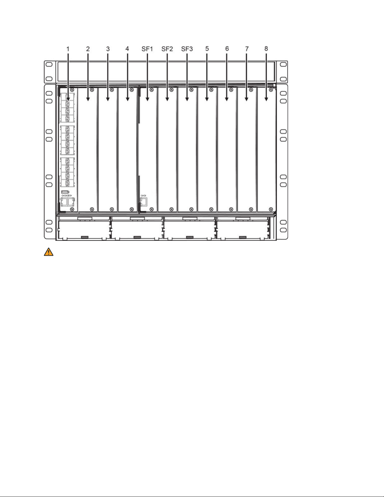
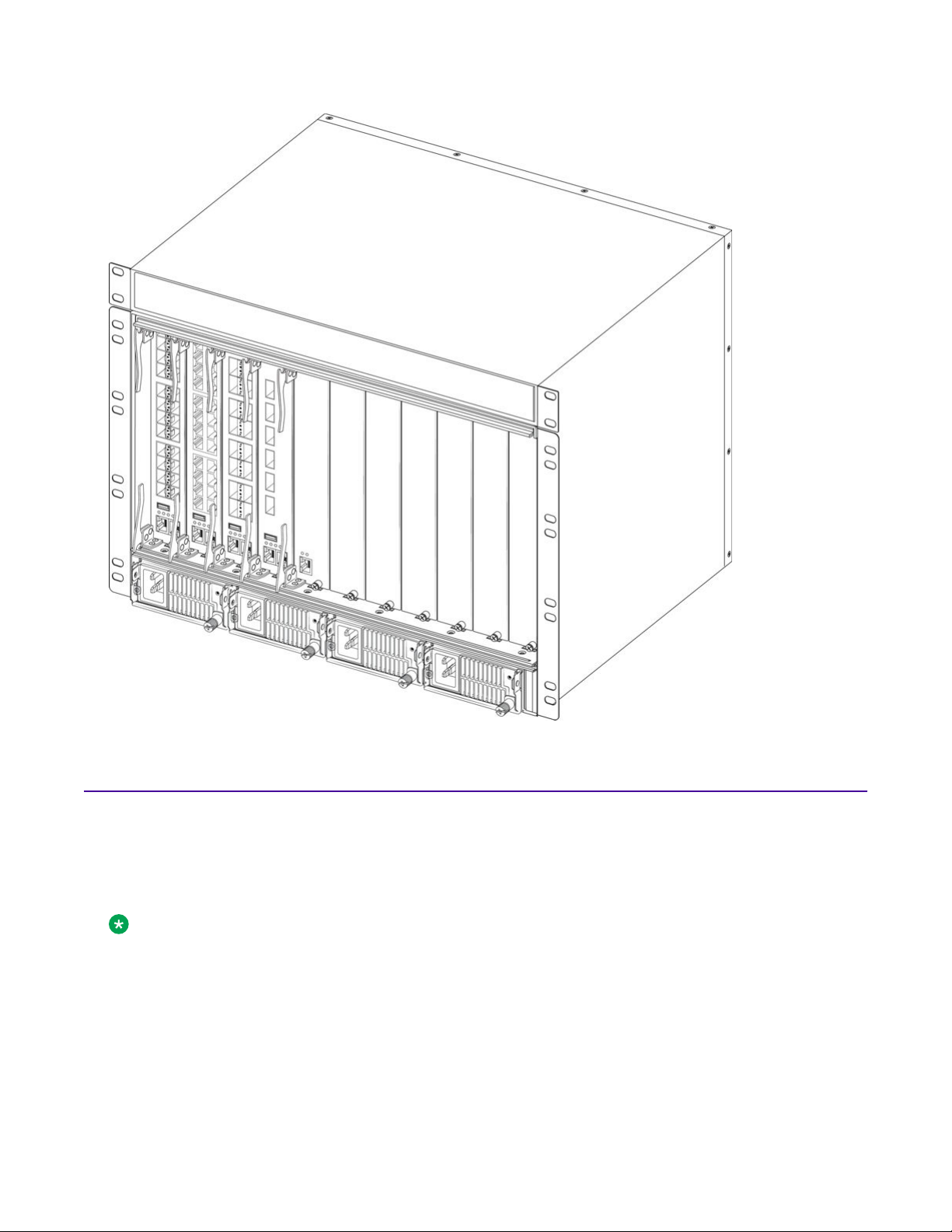
The following figure shows the slot designations for the VSP 8608 chassis. From left-to-right, slots 1
through 4 are designated for I/O and control (IOC) modules, followed by slots SF1 through SF3 for
switch fabric modules, and then slots 5 through 8 for IOC modules.
Hardware Component Specifications and Part Numbers on page 12.
September 2018 Installing the VSP 8600 15
Hardware fundamentals
Warning:
Keep the metal cover plate in place over empty module slots. An empty module slot allows air
into the chassis, which reduces the negative pressure in the chassis. This reduces airflow to the
installed modules.
The following figure shows an example of a populated VSP 8608 chassis with four IOC modules in
slots 1 through 4, a switch fabric module in slot SF1, and four AC power supplies.
September 2018 Installing the VSP 8600 16
Cooling modules
Cooling modules
The chassis includes five cooling module slots. The cooling modules plug directly into the backplane
at the rear of the chassis. Each module contains 2 x 80 mm fans. The backplane connects the fan
control signals to the I/O and control (IOC) slots.
Note:
This document uses the term cooling module to refer to the cooling fans within the VSP 8608
chassis. The terms fan, fan tray, and cooling unit (CU) also refer to the cooling fans within the
chassis.
The following figure shows the rear of the chassis with five cooling modules. Facing the rear, the
cooling modules are numbered CU1 through CU5 from left-to-right. The airflow direction is from
September 2018 Installing the VSP 8600 17
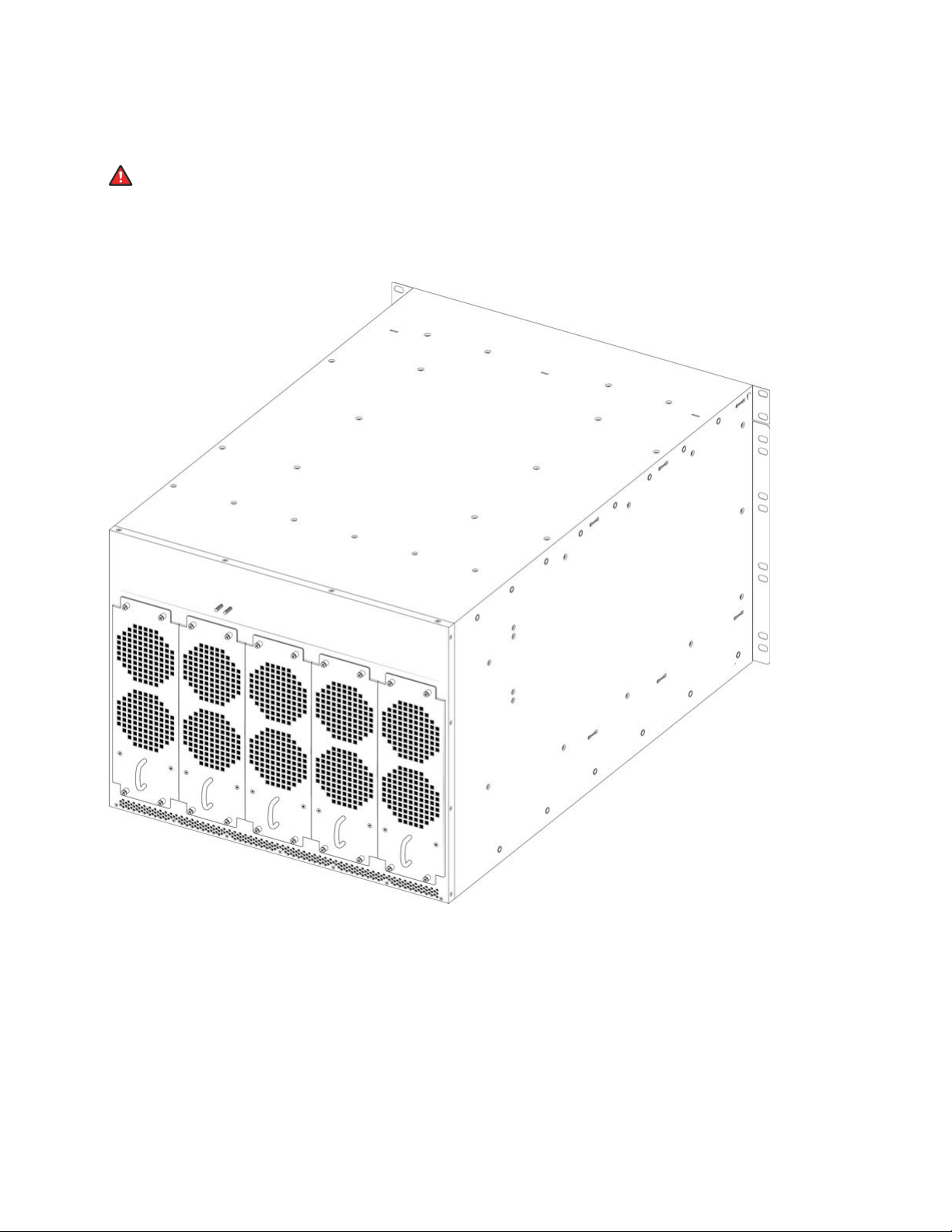
Hardware fundamentals
front-to-back. To ensure uniform airflow across all module slots, the fans in each cooling module
create a negative pressure that is evenly distributed across an internal plenum.
Danger:
Risk of personal injury
When you remove a cooling module, allow time for the fans to spin down before you fully
withdraw the cooling module. Be careful to keep your fingers out of the fan blades.
Fan speed
Inside the chassis, there are thermal sensors that monitor the temperature. The temperature
readings of the sensors send information to the central controller that automatically adjusts the
cooling module fan speed to maintain the proper temperature. For example, when the temperature
reading of the sensors decreases, the cooling module fan speed also decreases, which helps to
minimize fan noise. However, if one of the cooling modules fail or is temporarily removed, the speed
of the other cooling modules increase to their maximum rotational speed, which provides maximum
cooling to the chassis. The chassis can operate with a single cooling module failure and still
September 2018 Installing the VSP 8600 18
Cooling modules
maintain uniform airflow across all module slots. When all cooling modules are operational, the
internal temperature sensors determine the speed of the fans.
Warning:
Do not operate a chassis for more than a few minutes with a missing cooling module. To ensure
internal chassis air pressure is maintained and to avoid loss of traffic due to modules
overheating and shutting down, leave a failed cooling module installed until you have a
replacement.
Alarms are triggered when the temperature exceeds the following alarm thresholds—Warning,
Critical, and Shutdown.
Note:
%d represents a number for either a sensor, slot, or temperature.
The following list shows the log messages for the three threshold types:
• Warning—Temperature Sensor %d is (%d C) has exceeded the alarm threshold temperature
(%d C).
• Critical—Sensor %d slot %d temperature (%d C) exceeded the critical alarm threshold (%d C).
Module will be shut down at (%d C).
• Shutdown—Sensor %d in slot %d temperature (%d C) exceeded the shutdown threshold
temperature (%d C). Module has been powered down.
Alarms are cleared when the temperature cools by 2° below the threshold temperature. The
following list shows the log messages when an alarm is cleared:
• Critical threshold—Sensor %d in slot %d overheat critical alarm cleared
• Warning threshold—Temperature Sensor %d overheat temperature alarm cleared
You can use the following command to monitor current temperature, and view the threshold values
for Warning, Critical, and Shutdown.
show sys-info temperature
The following table provides a description of the various threshold limits:
Table 1: Alarm thresholds
Value
Sensor Index Specifies sensor IDs from 1 to 5. There are five sensors on each module.
Current temperature Specifies the current temperature sensor reading.
Warning threshold Specifies the temperature at which an alarm is raised.
Critical threshold Specifies the point at which a log message is generated. Action must be taken at
Shutdown threshold Specifies the critical maximum value where the module shuts down.
Description
this point otherwise the module is at risk of reaching the shutdown threshold.
Table continues…
September 2018 Installing the VSP 8600 19
Hardware fundamentals
Value Description
Note:
If a module enters a shutdown state, upon return to normal state, the
module must be powered on.
Normal state is when the temperature is below the Warning threshold value,
and there is no alarm on the system.
Important:
In a situation where there is a single module in either IOC slot 1 or 2 that
runs the control plane (CP) software and the module reaches the maximum
value, the switch shuts down. If redundancy is in place where there are
modules in both IOC slots 1 and 2, and one of these modules reaches the
maximum value, the switch remains operational.
Example
The following table shows an example of the threshold values for each temperature sensor in
degrees Celsius (° C):
VSP8608-1:1>show sys-info temperature
Temperature Info :
Card Card Sensor Sensor Current Warning Critical Shutdown
Index Description Index Description Temperature Threshold Threshold Threshold
1 8624XT 1 CPU 47 90 100 105
1 8624XT 2 MAC 49 100 105 110
1 8624XT 3 PHY/POLL 50 60 65 70
1 8624XT 4 MAC2 64 100 105 110
1 8624XT 5 CPU2 58 90 100 105
2 8624XS 1 CPU 42 90 100 105
2 8624XS 2 MAC 42 100 105 110
2 8624XS 3 PHY/POLL 45 60 65 70
2 8624XS 4 MAC2 54 100 105 110
2 8624XS 5 CPU2 53 90 100 105
4 8606CQ 1 CPU 36 90 100 105
4 8606CQ 2 MAC 46 100 105 110
4 8606CQ 3 PHY/POLL 34 60 65 70
4 8606CQ 4 MAC2 62 100 105 110
4 8606CQ 5 CPU2 49 90 100 105
SF 1 8600SF 1 CPU 34 90 100 105
SF 1 8600SF 2 MAC 58 100 105 110
SF 1 8600SF 3 PHY/POLL 43 70 75 80
SF 1 8600SF 4 MAC2 77 100 105 110
SF 1 8600SF 5 CPU2 44 90 100 105
SF 2 8600SF 1 CPU 34 90 100 105
SF 2 8600SF 2 MAC 58 100 105 110
SF 2 8600SF 3 PHY/POLL 43 70 75 80
SF 2 8600SF 4 MAC2 78 100 105 110
SF 2 8600SF 5 CPU2 44 90 100 105
Each cooling module contains two fans. Use the following command to monitor the status of each
fan in all five cooling modules:
show sys-info fan
VSP8608-1:1>show sys-info fan
Tray Unit CurrSpeed AirflowType Temperature Status
1 1 REGULAR F2B 27 OK
September 2018 Installing the VSP 8600 20
1 2 REGULAR F2B 27 OK
2 1 REGULAR F2B 27 OK
2 2 REGULAR F2B 27 OK
3 1 REGULAR F2B 28 OK
3 2 REGULAR F2B 28 OK
4 1 REGULAR F2B 29 OK
4 2 REGULAR F2B 29 OK
5 1 REGULAR F2B 29 OK
5 2 REGULAR F2B 29 OK
IOC Modules
The input/output and control (IOC) modules occupy slots 1 through 4 and slots 5 through 8.
The front panel on each IOC contains an RJ–45 console port, OOB Ethernet management port,
USB port, and status LED indicators.
Electrostatic alert:
ESD can damage electronic circuits. Do not touch electronic hardware unless you wear a
grounding wrist strap or other static-dissipating device.
IOC Modules
Warning:
Keep the metal cover plate in place over empty module slots. An empty module slot allows air
into the chassis, which reduces the negative pressure in the chassis. This reduces airflow to the
installed modules.
You can power on the chassis before or after the modules are installed. However, you must have an
IOC module in either slot 1 or slot 2 for the system to operate. For redundancy purposes, you must
have an IOC module in both slots 1 and 2. The IOC modules in slots 1 and 2 run control plane (CP)
software, as well as I/O software for the local ports on the IOC module. The modules are hot
swappable. Install a filler panel in any unpopulated IOC slot.
Note:
For part numbers (including Trade Agreement Act (TAA) compliant part numbers), see
Hardware Component Specifications and Part Numbers on page 12.
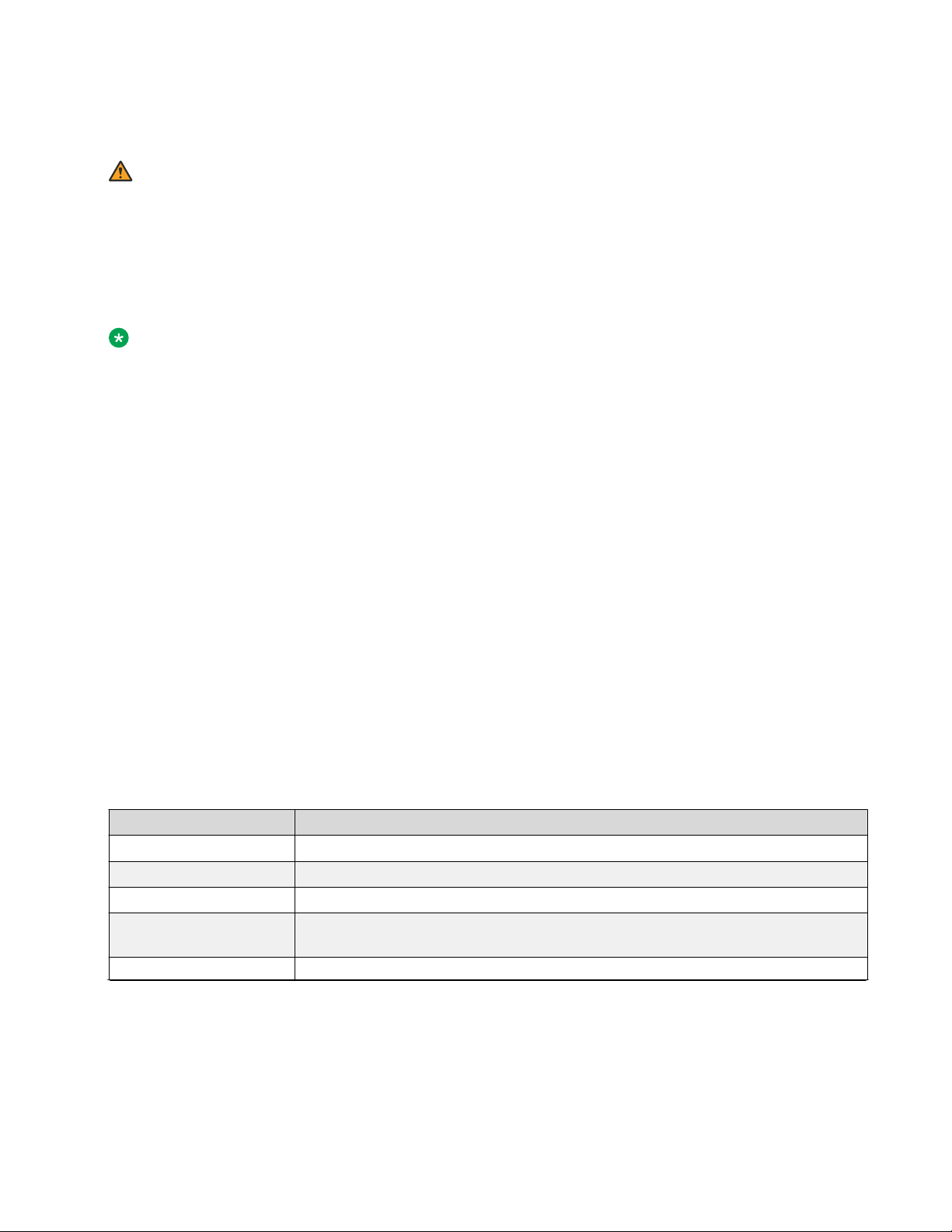
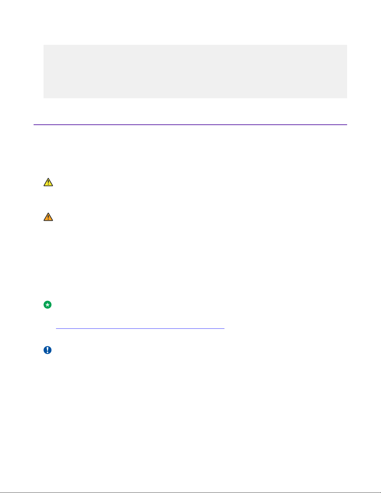
The chassis supports the following IOC modules:
Important:
The IOC modules in the following figures are shown in a horizontal position for description
purposes only. The IOC modules install vertically in the chassis.
September 2018 Installing the VSP 8600 21
Hardware fundamentals
8624XS
8624XT
8616QQ
8606CQ
The following table provides a description of the ports and LED indicators for all IOC models, as
shown in the preceding figures:
No.
1 8624XS: 24 port 1/10 Gbps SFP+ fiber ports
September 2018 Installing the VSP 8600 22
Model numbers and description
8624XT: 24 port 100 Mbps/1 Gbps/10 Gbps RJ–45 copper ports
Table continues…
IOC Modules
No. Model numbers and description
8616QQ: 16 port 40 Gbps QSFP+ ports, ports 1–4 support channelization
8606CQ: 6 port 100 Gbps QSFP28 ports, 40 Gbps QSFP+ ports, all 6 ports support channelization
2 USB port. The USB port is only active on the primary IOC module.
3 LED status indicators:
• PWR—system power
• Status—switch status
• RPS—redundant power supply
• Fan—cooling modules
Note:
LEDs are only operational on the primary IOC module.
4 RJ–45 out-of-band (OOB) management port. The management port is only active on the primary
IOC module.
5 RJ–45 serial console port. Default baud rate is 115200 bps.
MACsec Support for IOC Modules
The following table identifies the IOC modules that offer hardware and software MACsec support.
IOC Module
8624XS Yes Yes 128bit
8624XT No Yes 128bit
8616QQ No No N/A
8606CQ Yes Yes
Software MACsec
Support
Hardware MACsec
support
Note:
MACsec is not
supported on
channelized ports.
Encryption Support
128bit and 256bit
Channelization support
Channelization allows to configure a single port to operate as four individual ports. Channelization
can apply to the following port speeds:
• 40 Gbps (QSFP+) — when channelized, operates as four 10 Gbps ports
• 100 Gbps (QSFP28) — when channelized, operates as four 25 Gbps ports
Channelization on the 8616QQ module
The 8616QQ module supports channelization on the first four ports only. By default, the ports are
not channelized, which means that the 40 Gbps QSFP+ ports operate as 40 Gbps ports. You can
September 2018 Installing the VSP 8600 23

Hardware fundamentals
enable or disable channelization on any of the first four ports. Ports 5-16 do not support
channelization.
Channelization enables you to configure 40 Gbps QSFP+ ports to operate as four separate 10 Gbps
ports. You can use either 40GBASE-CR4 (copper) or 40GBASE-SR4 (fiber) breakout cables to
connect the 10 Gigabit Ethernet ports to other servers, storage devices, and switches. For breakout
cable details, see Installing Transceivers and Optical Components on VSP Operating System
Software.
Channelization on the 8606CQ module
The 8606CQ module supports channelization on all six 100 Gbps ports. The channelized port can
operate as four 25 Gbps ports if QSFP28 cables are used or four 10 Gbps ports if QSFP+ cables
are used. This allows the 100 Gbps port to operate as a 40 Gbps port with the sub-ports operating
at 10 Gbps speed. You can use 40GBASE-CR4 (copper) or 40GBASE-SR4 (fiber) or 100GBASECR4 (copper) or 100GBASE-SR4 (fiber) breakout cables to connect the 40/100 Gigabit Ethernet
ports to other servers, storage devices, and switches.
By default, the ports are not channelized. If channelization is not enabled, the ports display the
existing port format as “slot/port”. Once channelization is enabled, ports display the format as “slot/
port/sub-port” in the input/output.
MACsec is not currently supported on the channelized 10G/25G ports on the 8606CQ. If a MACsec
enabled port is channelized, then the MACsec configuration on that port will be lost.
Considerations
• 10 Gbps ports may indicate a link up state error, which represents a misconfiguration and can
create a black hole for packets. This can only happen if all of the following conditions are true:
- A QSFP+ with a fiber breakout cable is installed in a 40 Gbps port.
- The 40 Gbps port connected to the breakout cable is not yet channelized.
- The 40 Gbps port is administratively up.
- Any, or all, of the 10 Gbps ports connected to the other end of the breakout cable are
administratively up.
To avoid this error, set the 40 Gbps port to administratively down prior to installing the
channelization breakout cable.
FEC configuration support
Configure Forward Error Correction (FEC) on a port to obtain error control in data transmission over
an unreliable or noisy channel. You can configure FEC on 100 Gbps ports or on channelized 100
Gbps ports operating at 25 Gbps speed.
The following FEC options are supported:
• Clause 91
• Clause 108
• Clause 74
September 2018 Installing the VSP 8600 24

Switch fabric modules
FEC configuration on the 8606CQ module
The 8606CQ module supports FEC configuration on all six 100 Gbps ports and on channelized 100
Gbps ports operating at 25 Gbps speed. On a 100 Gbps port, only the Clause 91 and Clause 108
options are supported. On the channelized ports, you can configure either Clause 108 for extra
latency or Clause 74 for reduced latency.
FEC is not supported on a 100 Gbps port operating at 40 Gbps speed or on a management port.
Important:
On ports that support FEC configuration, ensure that you configure the same option at both endpoints. Otherwise, the link does not come up.
For more information on FEC, see Administering.
MACsec Encryption Cipher Suites
The 8606CQ module supports configuration of a cipher suite for MACsec encryption. You can
configure either the GCM-AES-128 cipher suite with a maximum key length of 128 bits, or the GCMAES-256 with a maximum key length of 256 bits. The default cipher suite is the GCM-AES-128. The
256-bit algorithm provide enhanced security and includes the security provided by the 128-bit
algorithm.
Note:
You cannot configure a MACsec cipher suite on a channelized port of the 8606CQ module.
For more information on how to configure a cipher suite on a port, see Configuring Security.
Switch fabric modules
The three center slots are dedicated to switch fabric (SF) modules. Two SF modules provide enough
switching bandwidth to accommodate all the populated modules (including the highest speed
modules). The control processors (CP) on the SF modules provide functions such as fabric
initialization and multicast table updates on the SF.
The processors located in IOC slots 1 and 2 use a gibabit-Ethernet connection to communicate with
the switch fabric modules in slots SF1 through SF3. The modules are hot swappable.
The number of SF modules that you require for redundancy depends on the types of modules
installed. Use the following examples to provide a guide for redundancy:
• If you have installed only 24 port, 10 Gbps IOC modules, you require two SF modules to
provide 1+1 redundancy, where one SF module supports the bandwidth and the second SF
module provides redundancy.
• If you have higher speed IOC modules (40 Gbps and 100 Gbps), you require two SF modules
to support the bandwidth and a third SF module to provide 2+1 redundancy.
September 2018 Installing the VSP 8600 25
Hardware fundamentals
Note:
For the part number (including Trade Agreement Act (TAA) compliant part number), see
Hardware Component Specifications and Part Numbers on page 12.
Electrostatic alert:
ESD can damage electronic circuits. Do not touch electronic hardware unless you wear a
grounding wrist strap or other static-dissipating device.
Warning:
Keep the metal cover plate in place over empty module slots. An empty module slot allows air
into the chassis, which reduces the negative pressure in the chassis. This reduces airflow to the
installed modules.
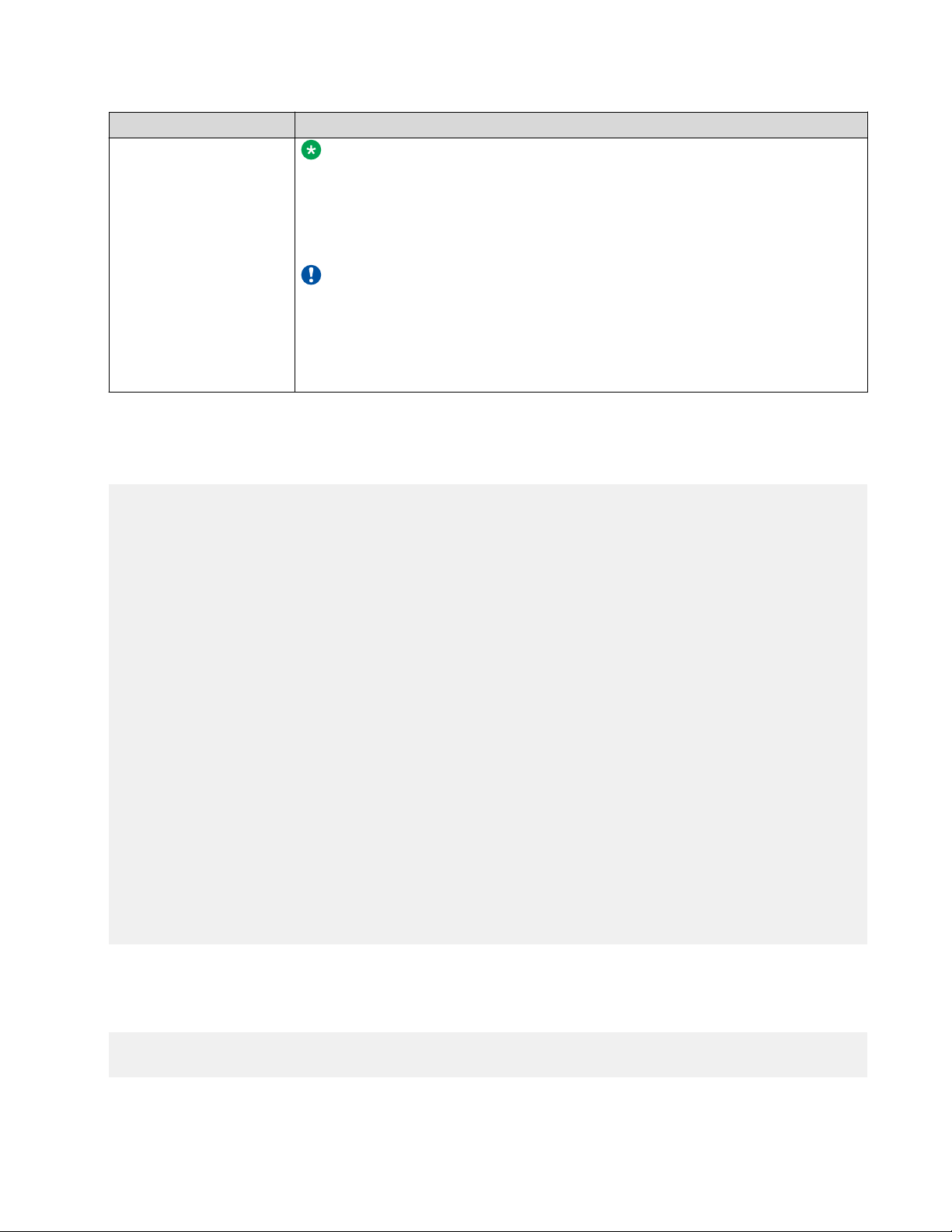
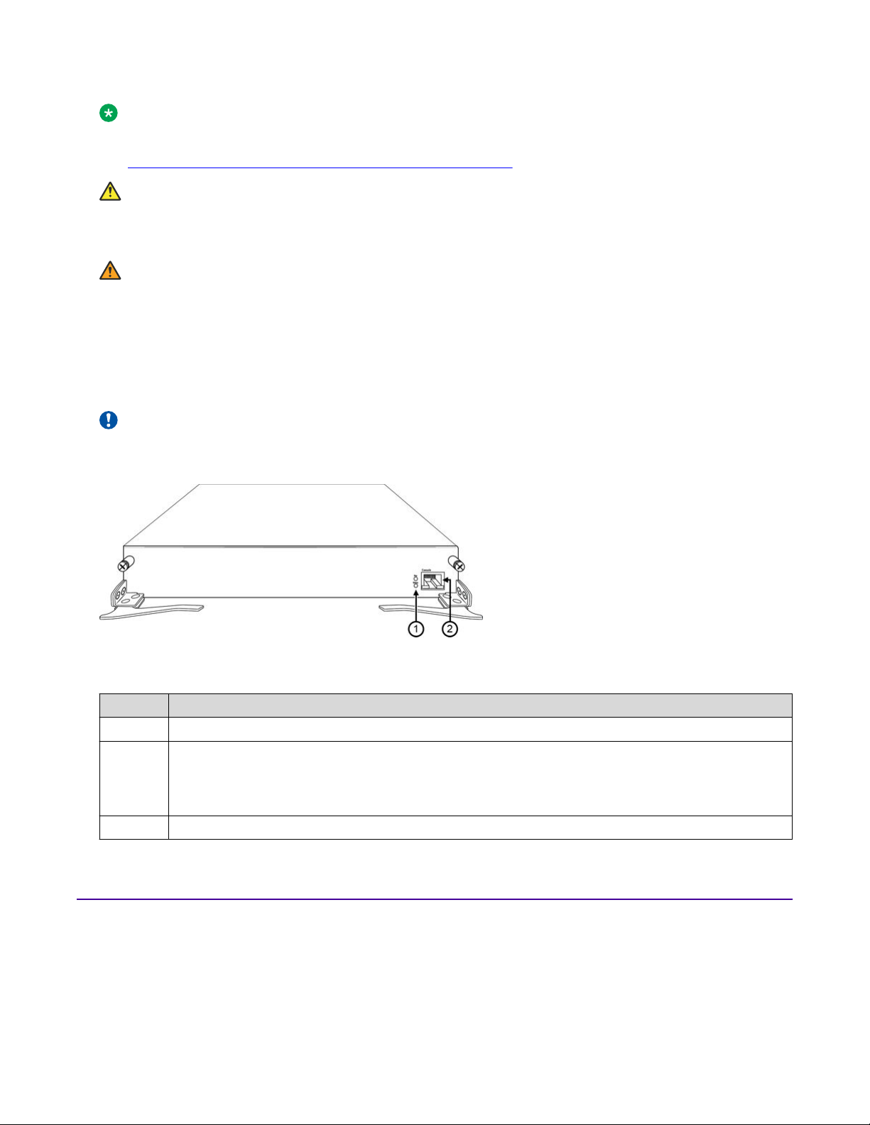
8600SF
The chassis supports the following switch fabric module:
Important:
In the following figure, the switch fabric module is shown in a horizontal position for description
purposes only. The switch fabric modules install vertically in the chassis.
The following table provides a description of the LED indicator and port for the switch fabric module,
as shown in the preceding figure:
No.
1 LED status indicators:
2 RJ–45 serial console port
Model number and description
8600SF: 3.6 Tbps of fabric bandwidth
• Pwr—system power
• Status—switch status
Pluggable transceivers and DACs
For information about supported optical transceivers, see Installing Transceivers and Optical
Components on VSP Operating System Software.
September 2018 Installing the VSP 8600 26
AC and DC power supply fundamentals
Port channelization
For ports that use channelization, use only breakout cables (copper direct attach cables (DAC) or
fiber). Otherwise, the link behavior can be unpredictable due to mismatched link status between link
partners, which can lead to additional network issues.
For non-channelized ports, do not use breakout cables.
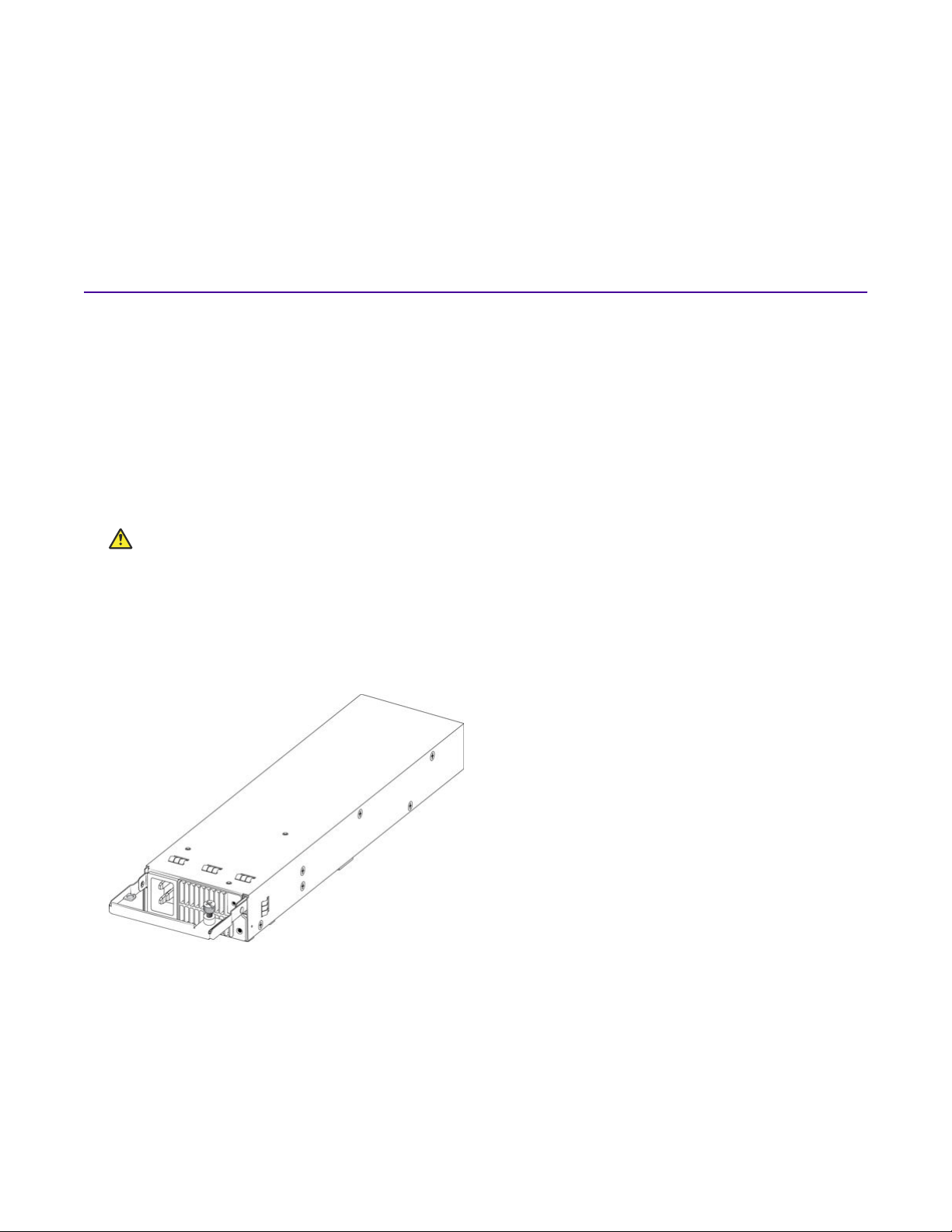
AC and DC power supply fundamentals
The chassis supports four 3,000 watt AC power supply units or 2,500 watt DC power supply units.
Each power supply is self enclosed and vents directly to the rear of the chassis; therefore, empty
power supply bays do not need a filler panel. If the chassis has more than one power supply
installed, you can hot swap a power supply on an operational switch.
You require one power supply to operate the chassis; however, the system software prevents some
of the IOC modules from entering a fully operational state if there is insufficient power available. As
you populate the chassis with more modules, additional power supplies might be required. Use the
Power Calculator tool to assist with calculating the power available versus the power load.
Caution:
Use the power calculator to determine if your AC power supply units (PSU) provide the correct
power capacity for your chassis configuration. In situations when your switch is heavily
populated, it is preferred that you connect to a 240–VAC power source to provide each AC PSU
with up to 3,000 watts. Or, in situations when your switch is lightly populated, you can connect to
a 120–VAC power source to provide each AC PSU with approximately 1,400 watts.
AC power supply
September 2018 Installing the VSP 8600 27
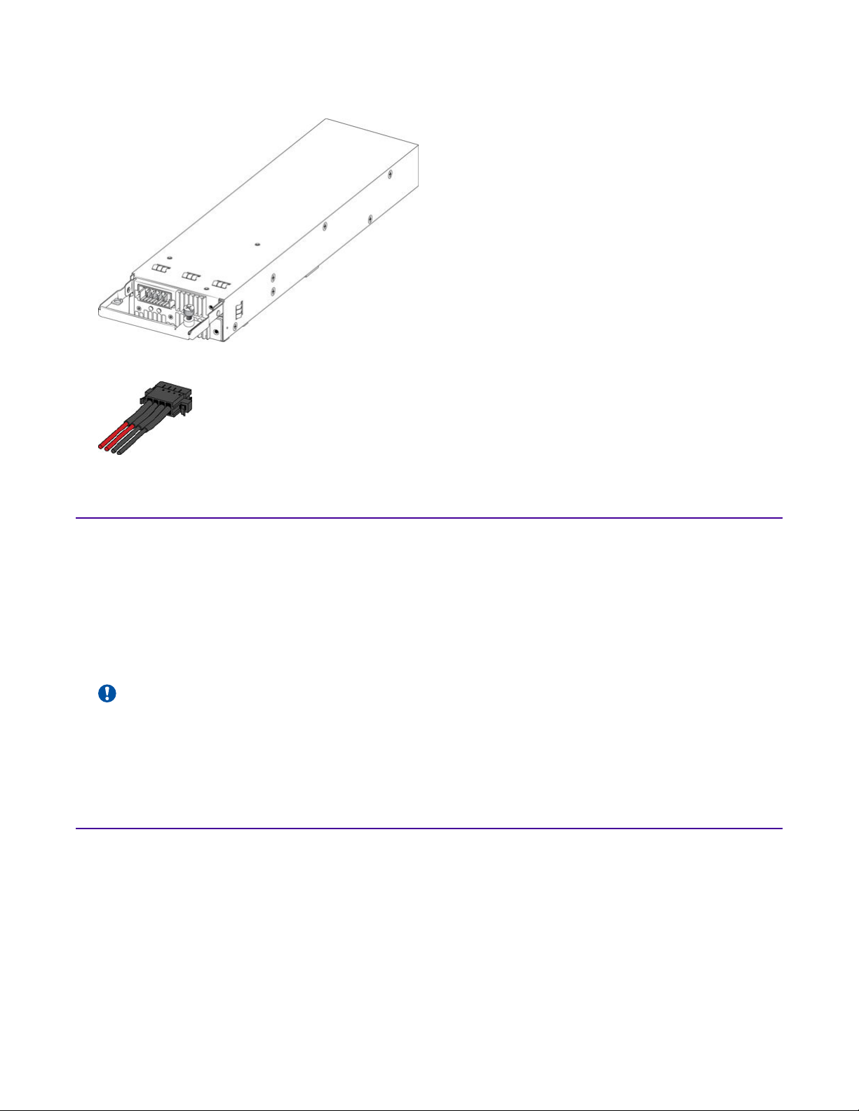
Hardware fundamentals
DC power supply
DC power cable:
Power calculator tool
Use the power supply calculator tool to help you determine the power requirement when configuring
the chassis, I/O and control (IOC) modules, switch fabric modules, optical transceivers, and power
supplies. This tool can be used to calculate the available power from the power supplies and the
power consumption for each IOC and each populated port. The results provide typical and
maximum power consumption, which helps you to determine your power reserve (power margin) to
ensure you do not exceed the maximum power allotted for all power supplies.
Important:
You require a basic knowledge of the various transceiver types and quantities used with each
line card. This tool does not alert you if port devices are incorrectly selected for a card or if
incorrect quantities of port devices are selected.
Console port pin assignments
The following table provides the supported console port pin assignments for the RJ-45 connectors.
September 2018 Installing the VSP 8600 28
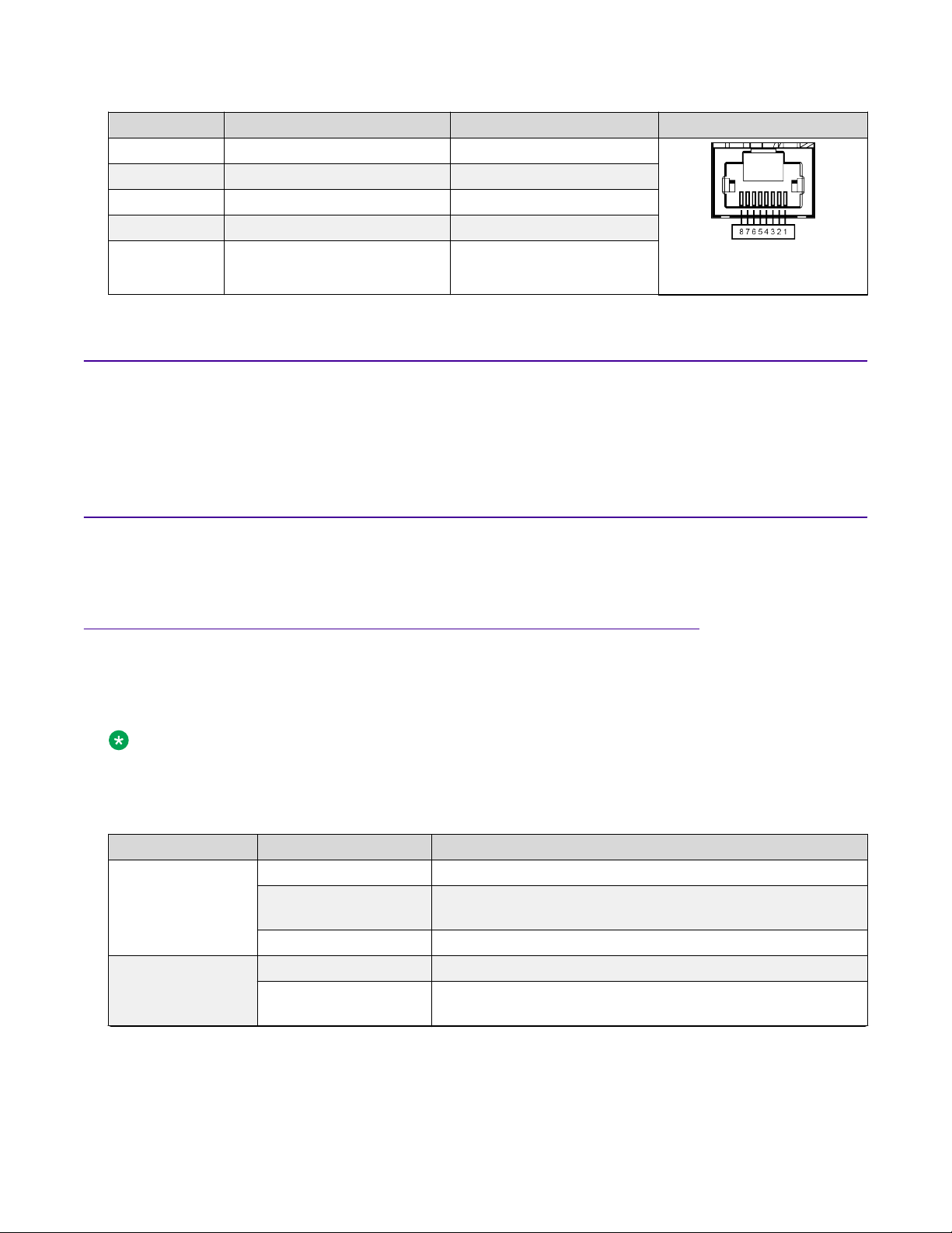
Pin number Signal Requirement Connector
1 Ready to send (RTS) Optional
3 Transmit data (TXD) Mandatory
5 Ground (GND) Mandatory
6 Receive data (RXD) Mandatory
8 Clear to send (CTS) Optional
(can swap or link with pin 1)
Airflow direction
The airflow direction is front-to-back. Air enters through the front panel on each module and is
exhausted through the rear of the chassis.
Airflow direction
Status LEDs
The following section provides information about the LED states for the various modules.
System status LEDs
The primary I/O and control (IOC) module provides the overall system status LEDs for the chassis,
switch fabric modules, and IOC modules.
Note:
Although all the modules contain LEDs, only the primary module in slot 1 reports on the overall
system state. If the primary module in IOC slot 1 fails, the standby module in slot 2 provides
failover, and takes the role as the primary module.
LED State Description
PWR Off No power and not operational.
Green (steady) Power is provided to the switch through either the primary or
secondary power supply.
Green (blinking) The switch is resetting.
Status Off No power and not operational.
Amber (steady) The diagnostic software is running and an error has been
encountered.
Table continues…
September 2018 Installing the VSP 8600 29
 Loading...