

Extreme Networks Summit X670-G2-72x, Summit X670-G2-48x-4q Quick Reference
X670-G2 Series Switch Quick Reference
The full Extreme Networks Summit Family Hardware Installation
Guide is available for download at the support website at:
www.extremenetworks.com/documentation
Hardware Components
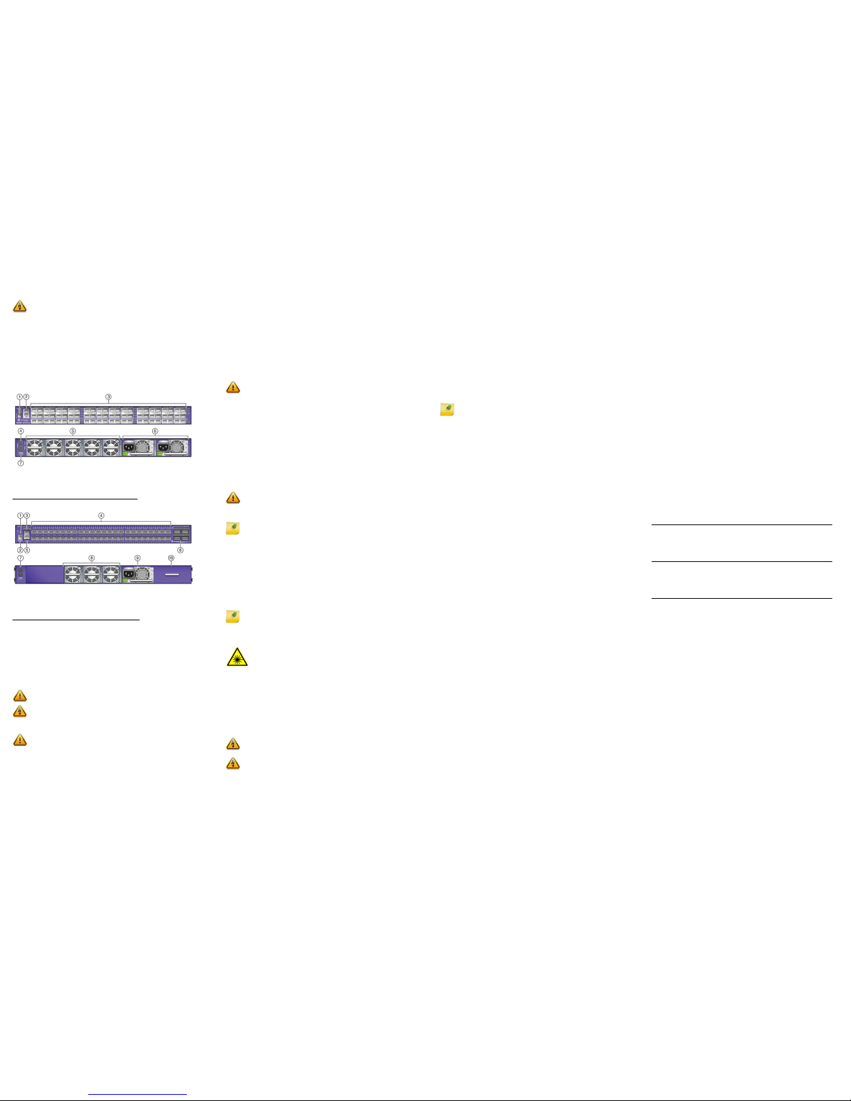
Figure 1 displays the panel ports, LEDs, and hardware components
on the X670-G2-72x switch. Figure 2 displays the panel ports,
LEDs, and hardware components on the X670-G2-48x-4q switch.
See the Extreme Networks Summit Family Hardware Installation
Guide for component details.
Figure 1 X670-G2-72x Front and Rear Panels
Figure 2 X670-G2-48x-4q Front and Rear Panels
Installation Site Requirements
The installation site must be within reach of the network cabling
and meet the requirements listed below:
• Appropriate grounded power receptacles must be located
within 6 feet of the site.
• A temperature of between 0°C (32°F) and 45°C (113°F) must be
maintained at the installation site with fluctuations of less than
10°C (18°F) per hour.
Handling the Switch
To prevent electrostatic damage, attach an electrostatic discharge
(ESD) wrist strap to your wrist before handling the switch.
Unpack the switch as follows:
1 Remove the packing material protecting the switch.
2 Remove the tape seal on the non-conductive bag to remove the
switch.
Electrical Hazard: Only qualified personnel should perform
installation procedures.
1 Stack LED 5 Fans
2 Console/Management ports 6 Power Supplies
3 SFP+ ports 7 USB port
4 Clock Output
1 USB port 6 QSFP+ ports
2 Stack LED 7 Clock Output
3 Console Port 8 Fans
4 SFP+ ports 9 Power Supply
5 Management port 10 Power Supply bay
cover
Caution: To ensure proper ventilation and prevent overheating,
leave a minimum clearance space of 5.1 cm (2.0 in.) on both sides of
the device.
Warning: A readily accessible disconnect device shall be
incorporated in the building installation wiring.
Caution: The switch can be damaged by electrostatic discharge.
3 Perform a visual inspection of the switch for any signs of
physical damage. Contact Extreme Networks if there are any
signs of damage. See “Getting Help” for more information on
contacting Extreme Networks.
Installing the Summit X670-G2 Series Switch
You can install a Summit X670-G2 Series switch in a rack. There are
four possible rack mounting configurations, depending upon
whether:
• The switch I/O ports or the power supply side of the device face
front
• The device is mounted flush with the rack posts or mid-mounted
Verify Fan Module and Power Supply Air Flow
Air flow direction is always from the perspective of the cool air
intake aisle (front of rack) to the hot air exhaust aisle (rear of rack).
Air flow can be either from:
• The switch I/O port side to the power supply side (front to
back)
• The power supply side to the switch I/O port side (back to
front)
Before installing the power supply into the Summit X670-G2 Series
switches, perform a visual verification that both power supply and
fan module air flows agree with the intended configuration.
Secure the Summit X670-G2 Series switches to the
Rack
To secure the Summit X670-G2 Series switches to the rack:
1 Attach the mounting brackets to the sides of the switch using
six screws for each bracket.
2 Align the rack mount ear holes with the front rack post holes.
3 Secure the Summit X670-G2 Series switches to each rack post
with at least two screws or fasteners appropriate to the rack.
Install SFP+ and QSFP+ Pluggable Transceivers
To install a transceiver in a Summit X670-G2 Series switch:
1 Attach the anti-static wrist strap. Refer to the instructions on
the anti-static wrist strap package.
2 Carefully align the transceiver with the port slot and push the
transceiver into the port slot until the transceiver clicks and
locks into place.
Connect Power to the Switch
After you have installed the power supply modules, you can
connect to a single, primary source of power, or to two sources of
power for redundancy. To power-up your X670-G2 Series switch:
1 Attach the power cord from your redundant power supply into
the X670-G2 Series switch’s power supply receptacle.
Caution: Ensure that the power supply and fan module air
flow are in the same direction in order to properly cool the
installed X670-G2 system.
Caution: Before rack-mounting the device, ensure that the
rack can support it without compromising stability.
Otherwise, personal injury and/or equipment damage may
result.
Note: The rack mounting brackets provide two holes for
securing the Summit X670-G2 Series switch to the rack.
Use two screws or fasteners appropriate to your rack on
each side when securing the X670-G2 Series switch to the
rack.
It is recommended that power supplies be installed after
Summit X670-G2 Series switches have been secured to the
rack to minimize weight that must be supported when
installing rack screws.
Note: If using one power supply, it can be installed in either of the
two power supply bays. If only one power supply is used, be sure to
insert a blank cover on the unused power supply bay. The blank
cover is provided with the switch.
Warning: Fiber-optic SFP+ and QSFP+ ports use Class 1 or Class 1M
lasers.
LASER RADIATION
DO NOT EXPOSE USERS OF TELESCOPIC OPTICS
CLASS 1 OR 1M LASER PRODUCT
Do not use optical instruments to view the laser output. The use of
optical instruments to view laser output increases eye hazard.
Warning: Extreme Networks power supplies do not have switches
for turning the unit on and off. Disconnect all power cords to remove
power from the device. Make sure that these connections are easily
accessible.
Warning: A dedicated Listed circuit breaker rated at 15A is to be
used for each power supply connection.
2 Once power is connected, verify that the PSU LED (P1 and/or
P2) turns green. If the PSU LED does not turn green, refer to the
Extreme Networks Summit Family Hardware Installation Guide
for troubleshooting information.
Selection of Power Cords
Extreme Networks does not include any AC power input cords. To
purchase the correct power cord for your specific country, refer to
www.extremenetworks.com/product/powercords/ for power cord
details to purchase a cord from Extreme Networks or your local
supplier.
Initial Network Connection and Configuration
Once you have connected power to the switch and verified LED
activity, complete the setup process as follows:
1 Connect a management station (your PC) to the console port
using either an Ethernet to serial adapter or DB-9 serial cable.
2 Verify that the switch system LEDs are on (solid green or
blinking green).
3 Using PuTTY, TeraTerm, or other terminal emulator, connect to
the switch using the serial port connection. Be sure that your
serial connection is set properly:
– 9600 baud
– 8 data bits
– 1 stop bit
4 Using the terminal emulator window connected through the
console port, perform the following:
a At the password prompt, press ENTER (RETURN) twice.
b Enter user: admin
c For the initial password, simply press ENTER.
d Follow the screen prompts for initial configuration. Press
ENTER to retain defaults or make changes as needed.
e Enter the show version command. Record the switch serial
number. The following is example output with the serial
number in bold:
Transit.3 # show version
Switch : 800444-00-05 0723G-01234 Rev 5.0 BootROM:
f Enter the command show switch. If the software image on
the switch is the version you need, then proceed to “Optional
CLI Commands”. If it is not the version you need, then
proceed to the next step to download the version you need.
5 Go to Extreme Networks e-support at
https://esupport.extremenetworks.com
If you are not already registered with the support site, create a
new account. After registering, you will be taken back to the
main eSupport web page.
6 After logging in, go to the product registration page:
http://extrwebapps.extremenetworks.com/Webapps/Public/
ProductReg/
7 Select your switch from the list and enter the serial number of
the switch. exactly as it appeared in the show switch command
output.
8 Using your eSupport login credentials, download the software
to your PC from the software download page at
https://extremeportal.force.com/ExtrDownloadLanding
9 Save the downloaded file to your PC. Be sure it is saved as a .xos
file type.
10 Using the terminal session, connect back to the switch via the
console session, and connect an Ethernet cable to the
management port on the switch to the Ethernet port on your
PC.
You might need to reset the IP address on your PC to some
address (for example, 10.10.10.10 255.255.255.0).
11 At the switch using the console session, set the IP address of the
switch (for example, enter: con mgmt ipa 10.10.10.9/24).
12 Enter save config to save your configuration.
13 Start a TFTP session using a program such as TFTPD64. Point
the TFTP server to your PC IP address and EXOS image file
saved on your PC.
14 At the switch, download the new software to the switch.
(example: download image 10.10.10.10 summitX-
15.4.1.3-patch1-9.xos). Press Enter.
15 Install the software after it loads by typing Y when prompted if
you want to install the load.
16 When the download and install finishes, accept the default
prompts.
17 Instruct the switch to reboot when prompted by entering:
reboot.
Note: If your PC does not have a serial port, you will need a
USB to serial adapter. to connect to the console port of the
switch.
Optional CLI Commands
Once logged into the switch you can create new VLANs by issuing
the following two commands:
• create vlan <vlan name>
• configure vlan <vlan name> tag XXXX (replace XXXX with
the VLAN tag number - options are 1-4096)
These two commands will create a VLAN, give it a logical name,
and assign a tag number.
To configure a Default Gateway in the Extreme Networks CLI enter:
configure iproute add default <IP Address>
Port Configuration CLI Commands
For additional port configuration CLI commands, refer to the
Extreme Networks XOS Command Reference Guide at:
www.extremenetworks.com/documentation
Specifications
Temperature and Humidity
Operating: 0° C (32°F) to 45° C (113° F)
Storage: -40° C to 70° C (-40° F to 158° F)
Operating relative humidity: 10% to 95% (non-condensing)
Switch Dimensions and Weight
X670-G2-72x Dimensions:
4.4 cm (1.73”) Height x 44.cm (17.4”) Width
x 48.7 cm (19.20”)
Length.
Packaged Weight: 9.43 kg (20.79 lbs.)
X670-G2-48x-4q Dimensions:
4.4 cm (1.73”) Height x 44 cm (17.4”)
Width x 48.7 cm (19.20”)
Length.
Packaged Weight: 9.08 kg (20.12 lbs.)
Interfaces
Each X670-G2 switch has a USB, console, and management port.
The following table lists the specific data interfaces for each model.
Power Supply Options
Table 1 X670-G2 Series Interface Descriptions
X670-G2-72x
(Part # 17300)
72 10GBASE-X SFP+ ports, ExtremeXOS
Advanced Edge License, unpopulated
dual PSU power slot and five
unpopulated fan module slots
X670-G2-48x-4q
(Part # 17310)
48 10GBASE-X SFP+ ports and 4
40GBASE-X QSFP+ ports, ExtremeXOS
Advanced Edge License, unpopulated
dual PSU power slot, and 3 unpopulated
fan module slots
X670-G2-72x (Part # 17300)
550 W AC Front to Back and
Back to Front Power Supply
550 W DC Front to Back and
Back to Front Power Supply
Part #: 10925 550W AC PS
FB (front to back),
Model #: DS550HE-3
Part #: 10927 550W AC PS
BF (back to front)
Model #:DS550HE-3-002
Part #: 10926 550W DC PS
FB (front to back),
Model #: DS550DC-3
Part #: 10928 550 W DC PS
BF (back to front)
Model #: DS550DC-3-003
100-240V~50/60 Hz, 2.75A,
max per PS
-48VDC, 6.75A max per PS
X670-G2-48x-4q (Part # 17310)
550 W AC Front to Back and
Back to Front Power Supply
550 W DC Front to Back and
Back to Front Power Supply
Part #: 10925 550W AC PS
FB (front to back),
Model #: DS550HE-3
Part #: 10927 550W AC PS
BF (back to front)
Model #:DS550HE-3-002
Part #: 10926 550W DC PS
FB (front to back),
Model #: DS550DC-3
Part #: 10928 550 W DC PS
BF (back to front)
Model #: DS550DC-3-003
100-240V~50/60 Hz, 2.25A
max per PS
-48VDC, 5.75A max per PS
Getting Help
For additional support related to X670-G2 series switches or this document,
contact Extreme Networks using one of the following methods:
Notice
Copyright © 2014-2017 Extreme Networks, Inc. All Rights Reserved.
Legal Notices
Extreme Networks, Inc., on behalf of or through its wholly-owned subsidiary,
Enterasys Networks, Inc., reserves the right to make changes in
specifications and other information contained in this document and its
website without prior notice. The reader should in all cases consult
representatives of Extreme Networks to determine whether any such
changes have been made.
The hardware, firmware, software or any specifications described or referred
to in this document are subject to change without notice.
Trademarks
Extreme Networks and the Extreme Networks logo are trademarks or
registered trademarks of Extreme Networks, Inc. in the United States and/or
other countries.
All other names (including any product names) mentioned in this document
are the property of their respective owners and may be trademarks or
registered trademarks of their respective companies/owners.
For additional information on Extreme Networks trademarks, please see:
www.extremenetworks.com/company/legal/trademarks/
Warranty
Warranty information for X670-G2 series switches is located online at
www.extremenetworks.com/go/warranty
Regulatory and Compliance Information
Federal Communications Commission (FCC) Notice
This device complies with Part 15 of the FCC rules. Operation is subject to
the following two conditions: (1) this device may not cause harmful
interference, and (2) this device must accept any interference received,
including interference that may cause undesired operation.
NOTE: This equipment has been tested and found to comply with the limits
for a class A digital device, pursuant to Part 15 of the FCC rules. These limits
are designed to provide reasonable protection against harmful interference
when the equipment is operated in a commercial environment. This
equipment uses, generates, and can radiate radio frequency energy and if
not installed in accordance with the operator’s manual, may cause harmful
interference to radio communications. Operation of this equipment in a
residential area is likely to cause interference in which case the user will be
required to correct the interference at his own expense.
WARNING: Changes or modifications made to this device which are not
expressly approved by the party responsible for compliance could void the
user’s authority to operate the equipment.
Industry Canada Notice
This digital apparatus does not exceed the class A limits for radio noise
emissions from digital apparatus set out in the Radio Interference
Regulations of the Canadian Department of Communications.
Le présent appareil numérique n’émet pas de bruits radioélectriques
dépassant les limites applicables aux appareils numériques de la class A
prescrites dans le Règlement sur le brouillage radioélectrique édicté par le
ministère des Communications du Canada.
Product
Documentation
https://www.extremenetworks.com/documentation/
Global Technical
Assistance Center
(GTAC)
Phone: 1-800-998-2408 (toll-free in U.S. and Canada)
or +1-408-579-2826. For the support phone number in
your country, visit:
http://www.extremenetworks.com/support/contact/
GTAC Knowledge
Get on-demand and tested resolutions from the GTAC
Knowledgebase, or create a help case if you need more
guidance.
Visit: https://gtacknowledge.extremenetworks.com/
The Hub
A forum for Extreme customers to connect with one
another, get questions answered, share ideas and
feedback, and get problems solved. The community is
monitored by Extreme Networks employees, but is not
intended to replace specific guidance from GTAC.
Visit: https://community.extremenetworks.com
Support Portal
Manage cases, downloads, service contracts, product
licensing, and training and certifications.
Visit: http://support.extremenetworks.com/
Class A ITE Notice
WARNING: This is a Class A product. In a domestic environment this
product may cause radio interference in which case the user may be
required to take adequate measures.
Product Safety
This product complies with the following: UL 60950-1, FDA 21 CFR 1040.10
and 1040.11, CAN/CSA-C22.2 No. 60950-1, EN 60950-1, EN 60825-1,
EN 60825-2, IEC 60950-1, 2006/95/EC.
Korea EMC Statement
Electromagnetic Compatibility (EMC)
This product complies with the following: FCC 47 CFR Part 15 (Class A),
ICES-003 (Class A), EN 55022 (Class A), EN 55024, EN 61000-3-2,
EN 61000-3-3, AS/NZS CISPR 22 (Class A), VCCI V-3, 2004/108/EC
(EMC Directive)
VCCI Notice
This is a class A product based on the standard of the Voluntary Control
Council for Interference by Information Technology Equipment (VCCI). If this
equipment is used in a domestic environment, radio disturbance may arise.
When such trouble occurs, the user may be required to take corrective
actions.
BSMI EMC Statement — Taiwan
This is a class A product. In a domestic environment this product may cause
radio interference in which case the user may be required to take adequate
measures.
Battery Warning — Taiwan
Battery Notice
This product contains a battery used to maintain product information. If the
battery should need replacement it must be replaced by Service Personnel.
Please contact Technical Support for assistance.
Caution: Risk of explosion if battery is replaced by an incorrect
type. Dispose of expended battery in accordance with local
disposal regulations.
Hazardous Substances - EU
This product complies with the requirements of Directive 2011/65/EU of the
European Parliament and of the Council of 8 June 2011 on the restriction of
the use of certain hazardous substances in electrical and electronic
equipment.
European Waste Electrical and Electronic Equipment (WEEE)
Notice
In accordance with Directive 2012/19/EU of the European Parliament on
waste electrical and electronic equipment (WEEE):
1 The symbol above indicates that separate collection of electrical and
electronic equipment is required.
2 When this product has reached the end of its serviceable life, it cannot be
disposed of as unsorted municipal waste. It must be collected and treated
separately.
3 It has been determined by the European Parliament that there are
potential negative effects on the environment and human health as a
result of the presence of hazardous substances in electrical and electronic
equipment.
4 It is the users’ responsibility to utilize the available collection system to
ensure WEEE is properly treated.
For information about the available collection system, please contact
Extreme Customer Support at +353 61 705500 (Ireland).
Extreme Networks
Summit X670-G2
Series Switches
Quick Reference
Summit X670-G2-72x
Summit X670-G2-48x-4q
P/N 120948-00
Hazardous Substances- China and Taiwan BSMI RoHS
Guidance concerning the China and Taiwan BSMI RoHS (Restriction of
Hazardous Substances) directive for this Extreme Networks® product can be
found on the following web page:
www.extremenetworks.com/support/documentation/restriction-hazardoussubstances/
The page contains tables detailing the presence of 10 substances defined by
the RoHS directive.
 Loading...