

Extreme Networks GBX, SummitGbX Installation And User Manual

™
SummitGbX
Installation
and User Guide
Extreme Networks, Inc.
3585 Monroe Street
Santa Cl ara, Cali fornia 950 51
(888) 257-3000
http://www.extremenetworks.com
Published: Septembe r 1999
Part number : 120040-0 0 rev. A

Copyright © Extreme Networks, Inc., 1998. All rights reserved. No part of this documentation may be
reproduced in any form or by any means or used to make any derivative work (such as translation,
transformation, or adaptation) without permission from Extreme Networks, Inc.
Extreme Networks, Summit, SummitGbX, and the Extreme Networks logo are trademarks of Extreme
Networks.
All other brand and product names are registered trademarks or trademarks of their respective
holders.
ii

SummitGbX
™
Installation and
User Guide
This document describes the features and installation of the Summit™ Gigabit Ethernet
Fiber-Optic Extender (GbX).
UMMIT
S
The SummitGbX Gigabit Ethernet Fiber Optic Extender greatly increases the maximum
single mode fiber interconnect distance between Gigabit Ethernet switches from the
standard IEEE 802.3z distance of 500 meters to 80 km (50 miles), or more. The
attenuation characteristics of t he installed fiber plant determine the maximum distan ce
that can be achieved. Links beyond 100 km are possible using an optical amplifier
option.
The SummitGbX is fully compatible with the Gigabit Ethernet IEEE 802.3z standard for
fiber optic interfaces.
Network manageme nt and loopback cont rol functions are provided by an RS-232 c port.
The SummitGbX supports full duplex operation as defined in IEEE 802.3x. This results
in 2 Gbps of actual link bandwidth, and provides lower latency, due to simultaneous
transmit and receive operations.
Figure 1 shows how the SummitGbX Extender offers network planners an important,
and fundamentally different, way to configure Gigabit Ethernet network by g iving users
interconnect distances up to 100 km. In m ost cases, the SummitGbX a llows much
greater freedom in the use of Summit and BlackDiamond
limitations cease to be a factor.
GbX O
VERVIEW
™
switches, as distance
Summit GbX Installation and User Guide 1
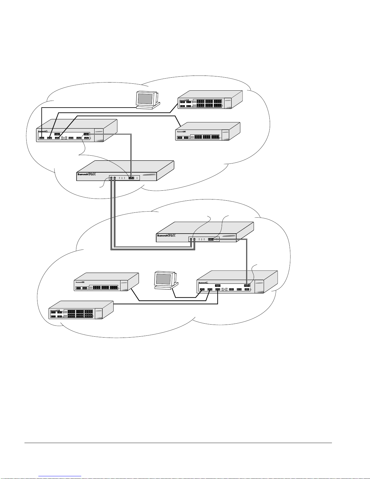
SummitGbX Overview
Building 1
SX Ports
MMF
LDI Port
Figure 1:
LDI Port
SMF
SummitGbX us ed in a typical co nfiguration
SX Port
Building 2
SX Port
GbX_cnx
2 Summit GbX Installation and Us er Guide
Summary of Features
UMMARY OF FEATURES
S
The SummitGbX extends the distance of Gigabit Ethernet links on Summit and
BlackDiamond switches to 8 0 kilometers using si ngle mode fiber. Depending on the
quality of fiber, distances of 100 kilometers, or more, can be achieved. The summary of
features is as follows:
• One full-duplex Gigabit Ethernet fiber optic interface and one full-duplex
long-distance fiber interfac e
• Full-duplex bandwidth operation with 2 Gbps throughput
• Highly reliable performance and a very low Bit Error Rate (BER) of 10
-12
• Standard duplex SC optical connector interface to Summit switches
• Standard SC optical connector for long-distance fiber interface
• Graphical user interface for management, using an RS-232c port
— Loopback diagnostic control
— Signal
— Loss of synch ronization
— Over-tem peratu re warnin g
• Low profile, 1U (1.75 inches)
• Standard 19-inch rack mount
• Dual, redundant, load sharing power supplies
UMMIT
S
GbX F
RONT VIEW
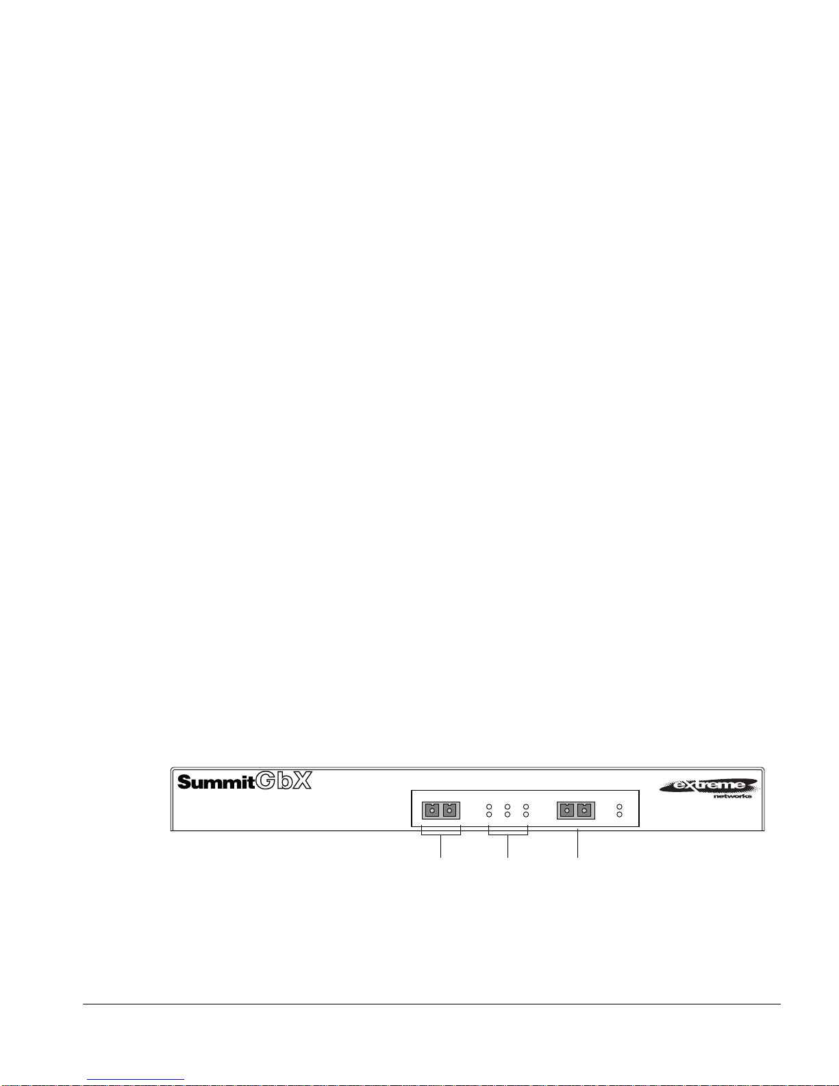
Figure 2 shows the front panel vi ew of the Summ itGbX.
RX
SYNC
FLT
LOSS
Status
LEDs
LOOP
BACK
Figure 2:
SummitGbX front pane l
LDI OPTICAL PORT
TX RX
CLASS 1 LASER
GBE
LDI
LDI ports Gigabit
GBE OPTICAL PORT
TX RX
CLASS 1 LASER
port
POWER
TEMP
LDI OPTICAL PORT
TX RX
CLASS 1 LASER
GbX_fr
Summit GbX Installation and User Guide 3

SummitGbX Front View
ORTS
P
The SummitGbX has one 1000BASE-SX port for connecting the SummitGbX to a
Summit or BlackDiamond switch, and one single mode long -distance interface (LDI) for
connecting between two SummitGbX units. Each 1000BASE-SX and LDI port has one
optical transmitter interface (TX) and one optical receiver interface (RX).
S
LED
Table 1 describes the LED behavior on the SummitGbX.
Table 1:
LED Color Indicates
RX FLT
(Receive F ault)
SYNC LOSS
(Synchronization Loss)
LOOP BACK Green
POWER Green Power on
TEMP Green
EDIA TYPES AND DISTANCES
M
SummitGbX LEDs
Green
Yellow
Green
Yellow
Yellow
Yellow
Signal received
No signal received
Receive clock detected
Receive cl ock not det ected
In normal mode (no loopback)
Loopback mode
SummitGbX temperature normal
SummitGbX indicating an overheat condition
Supported media types and distances are described in Table 2.
Table 2:
Media Types and Distances
Media Type Standard Media Guaranteed Distance
850nm Multimode
Optics
4 Summit GbX Installation and Us er Guide
1000BASE-SX 50/125um Multimode Fiber
(500/500 MH z–km)
62.5/125um Multimode Fiber
(160/500 MH z–km)
62.5/125um Multimode Fiber
(200/500 MH z–km)
550 Meters
220 Meters
275 Meters

SummitGbX Front View
Table 2:
Media Types and Distances (continued)
Media Type Standard Media Guaranteed Distance
1550nm Single mode
10u Single mode Fiber 100 Kilometers
Optics
ONG DISTANCE INTERFACES
L
Table 3 describes the Long Distance Interface (LDI) specifications.
Table 3:
Parameter Minimum Typical Maximum
LDI Optical Transceiver
Optical Output Power 0dBm 1dBm See Note 1
Optical ExtinctionRatio 7dB
Center Wavelength 1530nm 1550nm 1565nm
Optical Rise/Fall Time 0.5ns
LDI Specificat ions
LDI Optical Receiver
Optical Input Power Sensitivity -34dBm -32dBm
Optical Input Power Maximum -8dBm
Operating Wavelength 1200nm 1550nm 1600nm
Optical Return Loss 27dB
Note 1:
receiver input power level is -8dBm. Therefore, there is a minimum of 9dB loss required for the link
to operate error-free. This minimum required loss can be achieved using a fiber length of 40 km
(0.25 dB/km provides 10dB loss), or by adding 10dB of fixed optical attenuator at the receiver end.
The transmitter output power level for the SummitGbX is +1dBm. The maximum allowable
Summit GbX Installation and User Guide 5
 Loading...