

Extreme Networks BlackDiamond 6804, Summit Summit48, BlackDiamond 6808, BlackDiamond 6816, Summit1i Hardware Manual
...
Extreme Networks, Inc.
3585 Monroe Street
Santa Clara, California 95051
(888) 257-3000
http://www.extremenetworks.com
Extreme Networks
Consolidated Hardware
Guide
Published: August 2 003
Part number: 10 0093-00 Rev. 04

2
©2003 Extreme Networks, Inc. All rights reserved. Extreme Networks, ExtremeWare, BlackDiamond, and Alpine are
registered trademarks of Extreme Networks, Inc. in the United States and certain other jurisdictions. ExtremeWare Vista,
ExtremeWorks, ExtremeAssist, ExtremeAssist1, ExtremeAssist2, PartnerAssist, Extreme Standby Router Protocol, ESRP,
SmartTraps, Summit, Summit1i, Su mmit4, Su mmit4/FX, Sum mit5i, Summ it7i, Summ it24, Summit 48, Summit 48i,
Summit Virtual Chassis, SummitLink, SummitGbX, SummitRPS and the Extreme Networks logo are trademarks of
Extreme Networks, Inc., which may be registered or pending registration in certain jurisdictions. The Extreme
Turbodrive logo is a service mark of Extreme Networks, which may be registered or pending registration in certain
jurisdictions. All other registered trademarks, trademarks and service marks are property of their respective owners.
Specifications are subject to change without notice.
All other registered trademarks, trademarks, and service marks are property of their respective owners.
For safety compliance information, see Appendix A.
Authors: Megan Mahar
Production: Megan Mahar

Extreme Networks Consolidated Hardware Guide 3
Contents
Preface
Introduction 13
Conventions 14
Related Publications 14
About This Guide 15
How To Use This Guide 15
Part 1 Common Features
Chapter 1 Summary of Common Switch Features
Software Im ages 19
Full-Duplex Support 20
Management Ports 20
Mini-GBIC Type and Hardware/Software Support 20
Mini-GBIC Types and Specifications 20
Safety Information 22
Preparing to Install or Replac e a Mini-GBIC 22
Installing and Re moving a Mini-GB IC 23
GBIC Type and Hardware/Software Support 24
GBIC Media Types and Distances 24
GBIC Specifications 25
Long Range GBIC System Budgets 28
Safety Information 29
Preparing to Install or Repla ce a GBIC 29
Installing or Replacin g a GBIC 30

4 Extreme Networks Consolidated Hardware Guide
Part 2 Site Planning
Chapter 2 Site Preparation
Planning Your Site 36
Step 1: Meeting Site Requirements 36
Step 2: Evaluating and Meeting Cable Requirements 36
Step 3: Meeting Power Requirements 36
Meeting Site Requirements 36
Operating Environment Requirements 36
Rack Specifications and Recommendations 45
Evaluating and Meeting Cable Requirements 47
Cabling Standards 47
Cable Labeling and Record Keeping 48
Installing Cable 48
RJ-45 Connector Jackets 51
Radio Frequency Interference 51
Making Network Interface Cable Connections 52
Meeting Power Requirements 52
Power Supply Requirements 53
AC Power Cable Requirements 53
Uninterruptable Power Supply Requirements 54
Applicable Industry Standards 55
Part 3 Summit Switch
Chapter 3 Summit Switch Overview
Summit Switch Models 59
Summary of Feature s 60
Summit “i” series and non-”i” series switches 60
Summit24e2 61
Summit24e3 61
SummitPx1 61
Summit 200 Series 62
Memory Req uirements 63
Port Connections 63
Following Safety Information 64
Chapter 4 Summit Switch Models
Switch Models 65

Extreme Networks Consolidated Hardware Guide 5
Summit1i Switch Front View 66
GBIC Ports 66
LEDs 67
Summit1i Switch Rear View 68
Power Sockets 68
Label 68
Reset Button 68
Console Port 68
Summit5i Switch Front View 69
GBIC Ports 70
LEDs 71
Summit5i Switch Rear View 71
Power Sockets 71
Label 72
Reset Button 72
Console Port 72
Management Port 72
Summit7i Switch Front View 73
GBIC Ports 74
LEDs 75
Reset Button 75
Console Port 75
Modem Port 76
Management Port 76
PCMCIA Slot 76
Summit7i Switch Rear View 76
Power Sockets 76
Label 77
Summit48i Switch Front View 77
GBIC Ports 77
LEDs 78
Summit48i Switch Re ar View 79
Power Sockets 79
Label 79
Reset Button 79
Console Port 79
Summit48si Switch Front View 80
Mini-GBIC Ports 80
Console Port 81
LEDs 81
Summit48si Switch R ear View 81
Power Supplies 81
Reset Button 82

6 Extreme Networks Consolidated Hardware Guide
Summit48si Power Supply LEDs 82
Summit48si Switch Bottom View 83
Labels 83
Summit1i, Summit5i, Summit7i, Summit48i, and Summit48si Switch LEDs 84
Summit4 Switch Front View 85
LEDs 85
Summit4/FX Switch Front View 86
LEDs 86
Summit4 Switch Rear View 87
Power Socket 87
Label 87
Console Port 87
Redundant Power Supply Port 87
Reset Button 88
Summit4 Switch LEDs 88
Summit24e2 Switch Front View 89
Console Port 89
GBIC Ports 89
LEDs 90
Summit24e2 Switch Rear View 90
Power Socket 90
Summit24e2 Switch LEDs 91
Summit24e3 Switch Front View 91
Mini-GBIC Ports 92
LEDs 92
Console Port 92
Reset Button 93
Software Requirements 93
Summit24e3 Switch Rear View 93
Power Socket 93
Label 93
Summit24e3 Switch LEDs 94
SummitPx1 Application Switch Front View 95
GBIC Network Interface 95
LEDs 95
Ethernet Man agement Port 95
Serial Managem ent Console Por t 95
Serial Managem ent Modem Port 96
Software Requirements 96

Extreme Networks Consolidated Hardware Guide 7
SummitPx1 Application Switch Rear View 96
Power Socket 96
Label 96
SummitPx1 Application Switch LEDs 97
Summit 200-24 Switch Front View 97
Console Port 98
Port Connections 98
LEDs 98
Software Requirements 98
Summit 200-24 Switch Rear View 99
Power Socket 99
Label 99
Summit 200-24 Switch LEDs 99
Summit 200-48 Switch Front View 101
Console Port 101
Port Connections 101
LEDs 102
Software Requirements 102
Summit 200-48 Switch Rear View 102
Power Socket 102
Label 102
Summit 200-48 Switch LEDs 103
Chapter 5 Summit Switch Installation
Mounting the Switch in a Rack 105
Placing the Switch on a Table or Shelf 109
Verifying a Successful Installation 109
Removing and Installing Summit48si Power Supplies 109
Installing the AC Power Cable Retaining Bracket 111
Removing the AC Power Cable Retaining Bracket from a Power Cable 112
Removing the Switch from a Rack 113
Part 4 Alpine Sw itch
Chapter 6 Alpine 3800 Series Switch Overview
Summary of Features 117
Port Connections 118
Switch Components 119
Alpine 3808 Switch 119

8 Extreme Networks Consolidated Hardware Guide
Alpine 3804 Switch 119
Alpine 3802 Switch 120
Power Supply 120
Following Safety Information 120
Chapter 7 Alpine 3800 Series Switch Chassis
Alpine 3800 Series Architecture 123
Alpine 3808 Switch Front View 123
Alpine 3808 Switch R ear View 125
Alpine 3804 Switch Front View 125
Alpine 3804 Switch R ear View 127
Alpine 3802 Switch Front View 127
Alpine 3802 Switch R ear View 130
Installing the Chassis 132
Rack Installation 133
Grounding the Alpine 3800 Series Chassis 135
Removing the Chassis 136
Chapter 8 Alpine 3800 Series Switch Power Supplies
Power Supply LEDs 138
Installing the Alpine 3808 and the Alpine 3804 AC Power Supply 139
Verifying a Successful Installation 141
Removing the Alpine 3808 and the Alpine 3804 AC Power Supply 141
Supplying Power to the Alpine 3802 AC Power Supply 142
Verifying a Successful Installation 143
Installing the Alpine 3808 and the Alpine 3804 DC Power Supply 143
Selecting the Cabling 144
Installing the Power Supply 144
Attaching the Cabling an d Supplying Power 147
Verifying a Successful Installation 148
Removing the Alpine 3808 and the Alpine 3804 DC Power Supply 148
Supplying Power to the Alpine 3802 DC Power Supply 149
Selecting the Cabling 150
Attaching the Cabling an d Supplying Power 150
Verifying a Successful Installation 151
Chapter 9 Alpine 3800 Series Switch Management Module
SMMi Memory 154
SMMi LEDs 154
Installing SMMi Modules 155
Verifying the SMMi Module Installation 156

Extreme Networks Consolidated Hardware Guide 9
Removing SMMi Modules 156
Chapter 10 Alpine 3800 Series I/O Modules
Configuring I/O Modules 159
GM-4Ti Module 161
GM-4Xi Module 162
GM-4Si Modu le 165
GM-WDMi Module 166
GM-16X
3
Module 168
GM-16T
3
Module 170
FM-32Ti Module 172
FM-24Ti Module 173
FM-24SFi Module 175
FM-24MFi Module 177
FM-8Vi Module 179
WM-4T1i Module 181
WM-4E1i Module 182
WM-1T3i Module 183
I/O Module LEDs 183
Installing I/O Modules 185
Verifying the I/O Module Installation 186
LED Indicators 186
Displaying Slot Statu s Information 186
Removing I/O Modules 187
Chapter 11 Alpine 3800 Series Switch Fan Tray
Alpine 3808 Fan Tray 189
Alpine 3804 Fan Tray 190
Alpine 3802 Fan Tray 190
Removing the Alpine 3808 or Alpine 3804 Fan Tray 191
Installing the Alpine 3808 or Alpine 3804 Fan Tray 192
Part 5 BlackDiamond Switch
Chapter 12 BlackDiamond 6800 Series Switch Overview
Summary of Features 197
Port Connections 198
Switch Components 199
BlackDiamond 6816 Switch 199
BlackDiamond 6808 Switch 200

10 Extreme Networks Consolidated Hardware Guide
BlackDiamond 6804 Switch 200
BlackDiamond Power Supplies 200
Switch Connectivity and the Backplane 200
Packet Switching and Rou ting 201
Following Safety Information 201
Chapter 13 BlackDiamond 6800 Series Switch Chassis
BlackDiamond 6800 Series Architecture 203
BlackDiamond 6816 Switch Front View 203
BlackDiamond 6816 Switch Rear View 205
BlackDiamond 6808 Switch Front View 206
BlackDiamond 6808 Switch Rear View 208
BlackDiamond 6804 Switch Front View 209
BlackDiamond 6804 Switch Rear View 211
Installing the Chassis 211
Rack Installation 212
Grounding the BlackDiamond 6800 Series Chassis 216
Removing the Chassis 216
Chapter 14 BlackDiamond 6800 Series Switch Power Supplies
220 VAC Power Supplies 220
110 VAC Power Sup plies 2 21
DC Power Supplies 222
Installing a BlackDiamond 6800 Series Power Supply 223
AC Power Cable and Plug 227
Selecting the DC Cabling 227
Preparing the DC Cabling 228
Attaching the DC Cabling 228
Verifying a Successful Installatio n 229
Removing a BlackDiamond 6800 Series Power Supply 229
Chapter 15 BlackDiamond 6800 Series Management Switch Module
MSM64i Activity 235
MSM64i Memory 235
MSM64i LEDs 236
Installing MSM64i Modules 237
Verifying the MSM64i Module Installation 239
Removing MSM64i Modules 240
Chapter 16 BlackDiamond 6800 Series I/O Modules
Configuring I/O Modules 241
G8Ti Module 243

Extreme Networks Consolidated Hardware Guide 11
G8Xi Module 244
G12SXi Module 246
G16X
3
Module 247
G24T
3
Module 250
WDMi Module 252
10GLRi Module 254
F48Ti Module 257
F96Ti Module 258
F32Fi Module 2 62
P3cSi, P3cMi, P12cSi, and P12cMi Modules 263
ARM 267
MPLS Module 270
A3cSi and A3cMi Modules 273
I/O Module LEDs 277
Installing I/O Modules 278
Verifying the I/O Module Installation 279
LED Indicators 279
Displaying Slot Statu s Information 280
Removing I/O Modules 280
Chapter 17 BlackDiamond 6800 Series Switch Fan Tray
BlackDiam ond 6816 Fa n Tr ays 283
BlackDiamond 6808 Fan Tray 284
BlackDiamond 6804 Fan Tray 285
Removing a BlackDiamond 6800 Series Fan Tray 286
Installing a BlackDiamond 6800 Series Fan Tray 288
Part 6 Switch Operation
Chapter 18 Initial Switch and Management Access
Connecting Equipment to the Console Port 293
Logging In for t he First Time 295
Part 7 Appendixes
Appendix A Safety Information
Important Saf ety Informa tion 2 99
Power 299
Power Cable 300

12 Extreme Networks Consolidated Hardware Guide
Fuse 300
Connections 301
Lithium Battery 301
Appendix B Switch Technical Specifications
Appendix C Module Technical Specifications
Alpine Modules 318
BlackDiamond Modules 327
Common Module Specifications 339
Index

Extreme Networks Consolidated Hardware Guide 13
Preface
This preface provides an overview of this guide, describes guide convent ions, and lists other
publications that might be useful.
NOTE
To e nsure proper op eration of your Extrem e Networks equipm ent, read this guid e before you instal l any
Extreme Networks equ ipment.
Introduction
This guide provides the required information to install an Extreme Networks® Summit™ switch, Alpine
®
switch, or BlackDiamond® switch. It al so contains in formation ab out site loc ation, swit ch functional ity,
and switch oper ation.
This guide is intended for use by net work administrators who a re responsible for installing and setting
up network equipment. It assu mes a basic working knowled ge of:
• Local Area Networks (LANs)
• Ethern et conc epts
• Ethernet switching and bridging concepts
• Routing concepts
• Simple Network Management Protocol ( SNMP)
See the ExtremeWare Software User Guide for information about configuring an Extreme Networks switch.
NOTE
If the information in t he Release Notes that ship ped with your switch di ffers from the informatio n in this
guide, follow the Release Notes.

14 Extreme Networks Consolidated Hardware Guide
Preface
Conventions
Table 1 and Table 2 list conventions used throughout this guide.
Related Publications
The Extreme Networks switch documentation set i ncludes:
• Extreme Networks Consolidated Hardware Guide (this guide)
• ExtremeWare Software User Guide
• ExtremeWare Quick Reference Guide
• ExtremeWare Software Command Reference Guide
• ExtremeWare Release Notes
Table 1: Notice icons
Icon Notice Type Alerts you to...
Note Important features or instructions.
Caution Risk of perso nal injury , system damage,
or loss of dat a.
Warning Risk of severe pe rsonal injury .
Table 2: Text conventions
Convention Description
Screen displays This typeface represents information as it appears on the screen,
or command syntax.
Screen displays bold This typeface represents commands that you type.
The words “enter”
and “type”
When you see the word “enter” in this guide, you must type
something, and then press the Return or Enter key. Do not press
the Return or En ter key when an instruct ion simply sa ys “type.”
[Key] names Key names appear in text in one of two ways:
• Referenc ed by thei r labels, s uch as “the Return key” or “the
Escape key”
• Written with brackets, such as [Return] or [Esc]
If you must press two or more keys simultaneously, the key names
are linked with a plus sign (+). Example:
Press [Ctrl]+[Alt]+[Del].
Words in italicized type Italics emphasize a point of information or denote new terms at the
place where they are defined in the text.

About This Guide
Extreme Networks Consolidated Hardware Guide 15
Documentation for Extreme Networks products is available from the Extreme Networks website a t the
following location:
http://www.extremenetworks.com/services/documentation/
You ca n select and download the follow ing Extreme Networks documentation from the Docum entation
section of the Services page:
• Release Notes (you must have a valid service contract to access the release notes)
• Software User Guides
• Hardware User Guides
• White Papers
• Troub leshooting Tools
• Preventative Maintenance
• Instructional Videos
• Archives
About This Guide
This guide describes how to prepare your site a nd how to install, maintain , and operate your Extreme
Networks switch. It contains informa tion on features that are common to all swi tches, as well as
switch-specific features. This guide contains seven parts:
• Common Features—Describes features that are shared by t he Extreme Networks family of switches.
This section describes software images, full- duplex support, management po rts, mini-GBIC and
GBIC modules and their installa tion.
• Site Planning—Describes how to evaluate, plan, and determine the location of your Extreme
Networks switch.
• Summit Switch—Describes the features that are specific to the Summit switch. This section provides
an overview of the Summit switch , information about mo del types, summary of feat ures, and
installation guidelines.
• Alpine Switch—Describes the features that are specific to the Alpine switch. This section provides an
overview of the Alpine switch, informa tion about model types, a su mmary of features, and
installation guidelines.
• BlackDiamond Switch—Describes th e features that are specific to the BlackDiamond switch. Th is
section provides an overview of the BlackDia mond switch, information a bout model types, a
summary of features, and insta llation guidelines.
• Switch Operation—Describes how to pow er on any Extreme Networks switch, verify the switch
installation, connect equipment to the con sole port, and log in to the switch for th e first time.
• Appendixes—Includes information abou t safety requirements and technical sp ecifications.
How To Use This Guide
Each chapter of this guid e contains information on how to success fully operate your Extreme Networ ks
switch. The Summit-, Alpine-, a nd BlackDiamond-specific ch apters contain informatio n that is
applicable to that family of sw itch only. All other chapters are applicable to any Extreme Networks
switch.

16 Extreme Networks Consolidated Hardware Guide
Preface
Switch-Specific Information
For switch-specific information, be sure to read the applicable switch-specific chapter. For example, if
you have a BlackDiamond swit ch and you need to remove and replace an I/O mo dule, see “Removing
I/O Modules” in Chapter 16 for details about how to remove and replace an I/O module in a
BlackDiamond chassi s.
Common Informa tion
For items applicable to any Extreme Networks s witch, make sure you read the appropriate chapter. For
example, to learn how to prepare your site for installing your Extreme Networks equipment, see
Chapter 2, “Site Preparation.”
This guide also contains appendices that describe:
• Switch safety issues
• Switch specifications
• Module specifications
Appendix A, “Safety Information” describes important safety issues such as power, power cables, and
fuses.
Appendix B, “Switch Technical Specifications” is organized according to th e family of switch: Summit,
Alpine, and BlackDiamond. This a ppendix describes switch specificatio ns such as physical dimensio ns,
weight, certifications, and power supply para meters.
Information that is comm on to all switches is described at the en d of the appendix.
Appendix C, “Module Tech nical Specifications ” is organized according to the fami ly of switch and
modules available for that swi tch, and describes module specifications such as physical dimensi ons,
weight, and standards.
Information that is comm on to all modules is described at t he end of the appendix.

Part 1
Common Features


Extreme Networks Consolidated Hardware Guide 19
1 Summary of Common Switch Features
This chapter describes the features that are shared in common by the Extreme Networks family of
switches. The following topics a re described in greater detail:
• Software Images on page 19
• Full-Duplex Support on page 20
• Management Ports on page 20
• Mini-GBIC Type and Hardware/Software Support on page 20
• GBIC Type and Hardware/Software Support on page 24
Software Images
When you receive a new Extreme Networks switch, be aware that an the ExtremeWare® software image
and a BootROM image has been preinstalled at the factory. To verify the software image you are
running on your switch, use the
show version command. The show version command displays the
hardware and software versions currently running on the switch . To ensure that you have the latest
software and BootROM image, go to the support login portion of the Tech Support page at:
http://www.extremenetworks.com/services/
If your switch is running ExtremeWare version 6.2 or later, the Power LED activity is different from
previous versions of ExtremeWare. All other LED activity is the same. See Table 3 for mo re information
about the Power LED activity on switches running ExtremeWare version 6.2 or later.
NOTE
If the information in t he Release Notes that ship ped with your switch di ffers from the informatio n in this
guide, follow the Release Notes.
Table 3: Power LED activity fo r switches running Ext remeWare version 6.2 or later
LED Color Indicates
Power LED Green
Amber
Off
The indicated power supply unit (PSU) is powered up.
A PSU is installed, but not connected to power.
The PSU is not receiving power or no PSU is present.

20 Extreme Networks Consolidated Hardware Guide
Summary of Common Switch Features
Full-Duplex Support
Extreme Networks switches provide full-duplex support for all ports. Th is means that frames can be
transmitted and received simultaneously, which, in effect, doubles the bandwidth that is available on a
link. Most ports on an Extreme Networks switch autonegotiat e for half-duplex or full-duplex operation.
Gigabit Ethernet and 100BASE-FX ports operate in full-duplex mode only i n accordance with technical
standards.
Management Ports
The 10/100BASE-TX Ethernet managem ent port allows you to communica te directly to the CPU of the
switch. You can plug an Ethernet cable directly from your lapto p into the management port. This
provides you with direct access into the switch and a llows you to view and locall y manage the switch
configurations.
Do not assign an in-band IP address to the management port VLAN. The management port VLAN is an
out-of-band VLAN, so if it is assigned an in-band IP address (an address where the source and
destination are in the same subnet), the switch will treat it as a normal VLAN and attempt to route
traffic through it.
The management port is located on the f ollowing Extreme Networks devices:
• Summit5i—The ma nagement port is located on th e back side of the switch
• Summit7i—The ma nagement port is located on th e front side of the switch
• Alpine—Switch Management Module (SMMi) for the Alpine series switch
• BlackDiamond—Management Switch Fabric Module (MSM64i) for the Bl ackDiamond series switch
Extreme Networks does not recommend that you use the managem ent port to route traffic to any front
panel port on the switch. The managemen t port is designed for switch managem ent purposes.
Mini-GBIC Type and Hardware/Software Support
The Summit48si, Summit24e3 and Summit series switches, the BlackDiamond G16X3 module, and the
Alpine GM-16X
3
module support the small form plugga ble (SFP) GBIC, also known as the mini-GBIC.
The switches and the modules identify the type of mini-GBIC th at is installed and verifies that the
mini-GBIC is an Extreme Networks-certified mini-GBIC.
Mini-GBIC Typ es and Specifications
There are three types of mini-GBIC interfaces:
• SX mini-GBIC , which confo rms to the 1000 BASE-SX sta ndard
• LX mini-GBIC, which conforms to the 1000BASE-LX standard
• ZX mini-GBIC, which conforms to the IEEE 802.3z standard
Use only Extreme Networks-certified mini-GBICs, available from Extreme Networks, into the
mini-GBIC port in the switch or module.

Mini-GBIC Type and Hardware /Software Sup port
Extreme Networks Consolidated Hardware Guide 21
Table 4 describes the specifications for the SX m ini-GBIC interface, Table 5 describes the specifications
for the LX mini-GBIC interface, and Table 6 describes the specifications for the ZX mini-GBIC interface.
Total optical system budget for the SX mini-GBIC is 11.5 dB. Extreme Networks recommends that 3 dB
of the total budget be reserved for losses induced by cab le splices/connectors and operating ma rgin.
While 8.5 dB remains available for cable induced attenuation, the 1000BASE-SX standard specifies
supported distances of 275 meters ove r 62.5 micron multimod e fiber and 550 m eters over 50 micron
multimode fiber. There is no minimum attenua tion or minimum cable length restriction.
Total optical system budget for the LX mini-GBIC is 13.5 dB. Measure cable plant losses with a 1310 nm
light source and verify this to be within budget. Wh en calculating the maximum distance attainable
using optical cable with a specified loss per kilo meter (for example 0.25 dB/km) Extreme Networks
recommends that 3 dBm of the total budget be reserved for losses induced by cable splices/connectors
and operating margin. Thus, 10.5 dB remains available for cable induced attenuatio n. There is no
minimum system budget or minimum cable length restriction because the maximum receive power is
the same as the maximum transmit power. There is no minimum attenuation or minimum cable length
restriction.
Table 4: SX mini-GBIC spec ifications
Parameter Minimum Typical Maximum
Transceiver
Optical output power -9.5 dBm -4 dBm
Center wavelength 830 nm 850 nm 860 nm
Receiver
Optical input power sensitivity -21 dBm
Optical input power maximum -4 dBm
Operating wavelength 830 nm 860 nm
General
Total system budget 11.5 dB
Table 5: LX mini-GBIC specifications
Parameter Minimum Typical Maximum
Transceiver
Optical output power -9.5 dBm -3 dBm
Center wavelength 1275 nm 1310 nm 1355 nm
Receiver
Optical input power sensitivity -23 dBm
Optical input power maximum -3 dBm
Operating wavelength 1270 nm 1355 nm
General
Total system budget 13.5 dB

22 Extreme Networks Consolidated Hardware Guide
Summary of Common Switch Features
The ZX mini-GBIC is compatible w ith and interoperates with long range GBICs. Fo r more information
about the budget requirements and minimum attenutation requirements of long range GBICs, see “Long
Range GBIC System Budgets” on page 28.
Safety Information
Before you begin the process of installing or replaci ng a mini-GBIC, read the safety inf ormation in this
section.
CAUTION
Mini-GBICs can emi t invisible lase r radiation. Avoid di rect eye exposure to beam.
Mini-GBICs are class 1 laser devices, and they operate at 3.3 V. Use only Extreme Networks-certified
mini-GBI C device s.
If you see an amber blinking mini-GBIC port status LED after you install a mini-GBIC into the
Summit48si, Summit24e 3 or Summit 200 series swi tch, BlackDiamond G16 X
3
module, or an Alpine
GM-16X
3
module, this means the mini-GBIC is not certified by Extreme Networks. To correct this
problem, install an Extreme Networks-certified mini-GBIC, available from Extreme Networks,
mini-GBIC port.
If you install a mini-GBIC n ot certified by Extreme Networks into an Alpin e GM-16X
3
module and
insert a cable to bring up the link , the port status LED remains “off” and an error specifying the use of a
non-Extreme Networks-certified mini-GBIC is sent to the sys log. To view the syslog and to determine
why the link is down, use the
show log command. To correct this problem, install an Extreme
Networks-certified mini-GBIC, available from Extreme Networks, into the m ini-GBIC slot in the
module.
Preparing to Install or Replace a Mini-GBIC
To ensure proper installation, complete the following five tasks before inserting the mini-GBIC:
1 Disable the port that is needed to install or replace the mini-GBIC.
2 Inspect and clean the fiber tips, coupler, and connectors.
3 Prepare and clean an external attenuator, if needed.
Table 6: ZX mini-GBIC specific ations
Parameter Minimum Typical Maximum
Transceiver
Optical output power -2 dBm 0 dBm 3 dBm
Center wavelength 1540 nm 1550 nm 1570 nm
Receiver
Optical input power sensitivity -23 dBm
Optical input power maximum -3 dBm
Operating wavelength 1540 nm 1550 nm 1570 nm
Mini-GBIC Type and Hardware /Software Sup port
Extreme Networks Consolidated Hardware Guide 23
4 Do not stretch the fiber.
5 Make sure the bend radius of the fiber is not less than 2 inches (5.08 cm).
In addition to the previously described tasks, Extreme Networks recommends the following when
installing or replacing mini- GBICs on an active net work:
• Use the same type of mini-GBIC at each end of the link .
• Connect one end of the link to the Tx port. Without an attenuator, measure the total loss from the Tx
port to the other site of the link. The total loss must not exceed the total optical sys tem budget.
After you complete these described tasks, you are ready to install or replace a mini- GBIC.
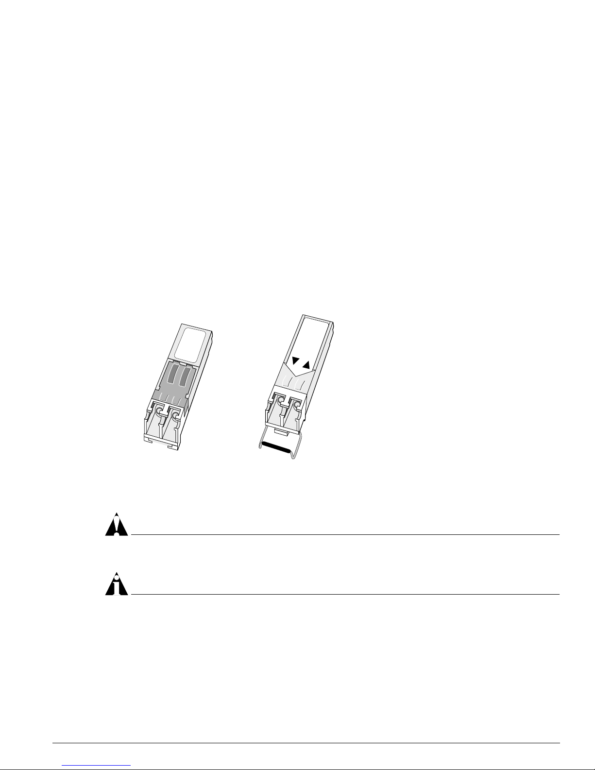
Installing and Removing a Mini-GBIC
You can add mini-GBICs into, or remove mini-GBICs from your Summit48si, Summit24e3, and Summit
200 series switches, Blac kDiamo nd G1 6X
3
module, or Alpine GM-16X3 module without powering off the
system. Figure 1 show s the two types of mini-GBIC connectors.
Figure 1: Mini -GBIC modules
Mini-GBICs are a 3.3 V Class 1 laser devices. Use only Extreme-approved devices.
CAUTION
Mini-GBICs can emi t invisible laser ra diation. Avoid direct eye exposure to beam.
NOTE
Remove the LC fiber-optic conn ector from the mini-GBIC prio r to removing the mini-G BIC from the
switch.
If you see an amber blinking mini- GBIC port status LED on your Summ it48si, Summit24e3, or Summ it
200 series swit ch, a Blac kDiamond G 16X
3
module, or an Alpine GM-16X3 module, the mini-GBIC
installed in your switch or mo dule is not approved, supported, or certified by Ext reme Networks. To
correct this problem, ensure that you install an Extreme Networks-certified mi ni-GBIC.
XM_024
Module A Module B

24 Extreme Networks Consolidated Hardware Guide
Summary of Common Switch Features
To remove a mini- GBIC similar to the one labeled “Module A” in Figure 1, gently depress and hold th e
black plastic tab at the bottom of the connector to release the mini-GBIC, and pull the mi ni-GBIC out of
the SFP receptacle.
To remove a mini-GBIC connector similar to the one labeled “Module B” in Figure 1, gently rotate the
front handle and pull the mini-GBIC out of the SF P receptacle.
To insert a m ini - GBIC c o nne c tor:
NOTE
Mini-GBICs can be ins talled in the SFP mini -GBIC receptacles onl y.
1 Holding the mini-GBIC by its side s, insert the mini-GBIC into the SFP receptacle on the switch or
module.
2 Slide the mini-GBIC into the S FP receptacle until you h ear an au dible click, indicating th e mini-GBIC
is securely seated into the SFP receptacle. If the mini-GBIC has a hand le, push up on the handle to
secure the mini-GBIC.
GBIC Type and Hardware/Software Support
Most Extreme Networks switches sup port two types of GBICs: the Pa rallel ID GBIC and the Serial ID
GBIC. The switch can identify the media type for the GBIC that is installed. Initial ExtremeWare
software versions do not support Serial ID GBICs. If Serial ID GBICs are installed in a switch with an
initial software release, the switch will not bring up the link on G BIC ports.
GBIC Media Types and Distances
Ta ble 7 des cribes the med ia types an d associated maximum di stances for e ach GBIC typ e.
Table 7: GBIC types and maximu m distances
Standard Media Type
Mhz•Km
Rating
Maximum
Distance (Meters)
SX
(850 nm optical window)
50/125 µm mu ltimode fi ber
50/125 µm mu ltimode fi ber
62.5/125 µm multimode fiber
62.5/125 µm multimode fiber
400
500
160
200
500
550
220
275
LX
(1310 nm optical window)
50/125 µm mu ltimode fi ber
50/125 µm mu ltimode fi ber
62.5/125 µm multimode fiber
10/125 µm single-mode fiber
10/125 µm single-mode fiber*
400
500
500
–
–
550
550
550
5,000
10,000
ZX
(1550 nm optical window)
10/125 µm single-mode fiber – 50,000
ZX Rev 03
(1550 nm optical window)
10/125 µm single-mode fiber 70,000

GBIC Type and Hardware/Software Support
Extreme Networks Consolidated Hardware Guide 25
*Extreme Networks proprietary. Connections between two Extreme Networks 1000BASE-LX interfaces can use a maximum distance of 10,000
meters.
GBIC Specifications
Table 8 through Ta ble 14 describe the specifications for each GBIC type.
LX70
(1550 nm optical window)
10/125 µm single-mode fiber – 70,000
LX100
(1550 nm optical window)
10/125 µm single-mode fiber 100,000
UTP Category 5 UTP cable – 80
Table 8: 1000BASE-SX specifi cations
Parameter Minimum Typical Maximum
Transceiver
Optical output power -9.5 dBm -4 dBm
Center wavelength 830 nm 850 nm 860 nm
Receiver
Optical input power sensitivity -17 dBm
Optical input power maximum 0 dBm
Operating wavelength 830 nm 860 nm
Table 9: 100BASE-LX s pecifications
Parameter Minimum Typical Maximum
Transceiver
Optical output power -11 dBm -3 dBm
Center wavelength 1270 nm 1310 nm 1355 nm
Receiver
Optical input power sensitivity -19 dBm
Optical input power maximum -3 dBm
Operating wavelength 1270 nm 1355 nm
Table 10: ZX GBIC specifications
Parameter Minimum Typical Maximum
Transceiver
Optical output power -4 dBm -3 dBm -1 dBm
Table 7: GBIC types and maxi mum distances (contin ued)
Standard Media Type
Mhz•Km
Rating
Maximum
Distance (Meters)

26 Extreme Networks Consolidated Hardware Guide
Summary of Common Switch Features
Identifying ZX GBIC Rev 03 Modules
To identi fy the type of ZX GBIC module you have, look at the label on the top of the ZX GBIC module.
If you see one of the followin g on the label, you have a ZX GBIC Rev 03 module:
• DVA-1203 sticker n ear the top of the label that covers the Extreme Networks logo
• ZX GBIC (1203) text near the top of the label
• ZX GBIC Rev 03 text near the center of the label
Center wavelength 1540 nm 1550 nm 1570 nm
Receiver
Optical input power sensitivity -23.5 dBm
Optical input power maximum -1 dBm
Operating wavelength 1540 nm 1550 nm 1570 nm
Table 11: ZX GBIC R ev 03 specifications
Parameter Minimum Typical Maximum
Transceiver
Optical output power -2 dBm 0 dBm 2 dBm
Center wavelength 1540 nm 1550 nm 1570 nm
Receiver
Optical input power sensitivity -23 dBm
Optical input power maximum -1 dBm
Operating wavelength 1540 nm 1550 nm 1570 nm
Table 12: LX70 GBIC specifications
Parameter Minimum Typical Maximum
Transceiver
Optical output power 0 dBm 3 dBm 5.2 dBm
Center wavelength 1540 nm 1550 nm 1570 nm
Receiver
Optical input power sensitivity -22 dBm
Optical input power maximum -3 dBm
Operating wavelength 1270 nm 1570 nm
Table 10: ZX GBIC specifications (continued)
Parameter Minimum Typical Maximum

GBIC Type and Hardware/Software Support
Extreme Networks Consolidated Hardware Guide 27
Requirements for the LX100 GBIC
This section describes the requirements for the LX100 GBIC. Read the information in this section before
you install an LX100 GBIC.
The Summit24 e2 switch does not support the LX100 G BIC. Do not ins tall an LX10 0 GBIC into t he
Summit24e2 switch.
If you have an Alpine 3800 series switch populated with a GM-4Xi module, do one of the following:
• Install a maximum of three LX100 GBICs per GM-4Xi module; the fourth GBIC slot must remain
empty
• Install two or less LX10 0 GBICs per GM-4Xi module a nd leave the remaining GBIC slo ts empty
• Install two or less LX 100 GBICs per GM-4Xi m odule and install an y combination of th e following
GBICs into the empty slots:
— 1000BASE-SX
— 1000BASE-LX
— ZX GBIC
— ZX Rev 03
— LX70
— UTP GBIC
To ensure correct operation of the LX100 GBIC, make sure that you run ExtremeWare 6.1.9 or later on
your switch.
Requirements for the UTP GBIC
The UTP GBIC operates in full-duplex mode only. The UTP GBIC does not operate in 10/100 Mbps
mode, and it does not suppo rt autonegotiation of li nk speed.
Table 13: LX100 GBIC specifications
Parameter Minimum Typical Maximum
Transceiver
Optical output power 1 dBm 3 dBm 5 dBm
Center wavelength 1546 nm 1551 nm 1557 nm
Receiver
Optical input power sensitivity -29 dBm
Optical input power maximum -7 dBm
Operating wavelength 1546 nm 1551 nm 1557 nm
Table 14: UTP GBIC specifications
Media Type
Bit Error Rate
(Errors per Second)
Data
Rate
Min Distance
(Meters)
Max Distance
(Meters)
Category 5 UTP cable 10
-12
1 Gbps 2 80
28 Extreme Networks Consolidated Hardware Guide
Summary of Common Switch Features
You need to dis able autonegotiation on the ports that use the UTP GBIC and manually configure the
port speed to 1000 Mbps.
The following example disables au tonegotiation, con figures a port speed of 1000 Mbps, and speci fies
full-duplex mode for port 4 on a stand-alone switch:
config ports 4 auto off speed 1000 duplex full
The following example disables au tonegotiation, con figures a port speed of 1000 Mbps, and speci fies
full-duplex mode for port 1 on a G8Xi module located in slot 1 of a modular switch:
config ports 1:1 auto off speed 1000 duplex full
The UTP GBIC is supported on “i” series products only.
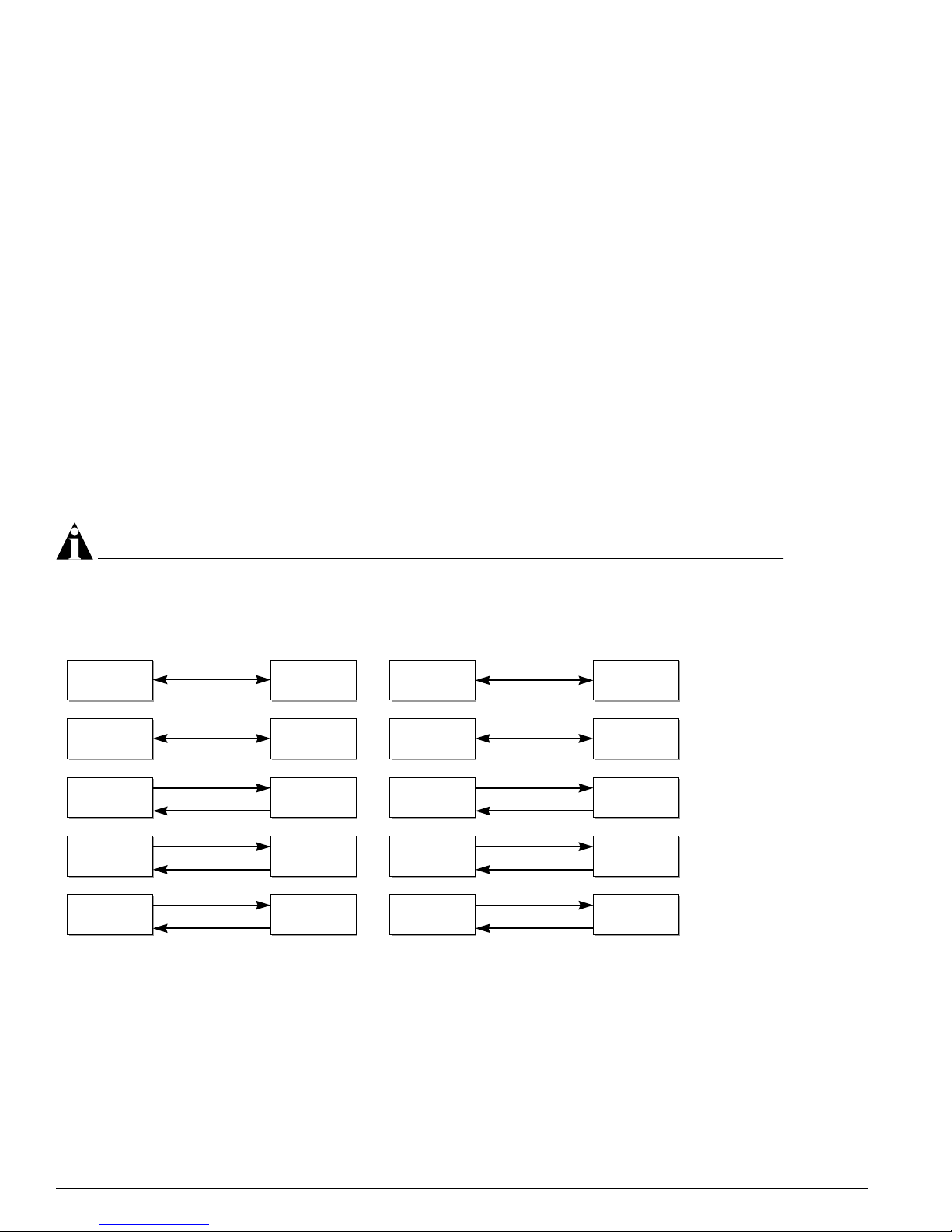
Long Range GBIC System Budgets
Measure cable plant losses with a 1550 nm ligh t source and verify this to be within bud get. When
calculating the maximum dis tance attainable, usi ng optical cable with a specified loss per kilometer (for
example, 0.25 db/km), Extreme Networks recommends that 3 dB of the total budget be reserved for
losses induced by cable splices, connectors, and o perating margin. Figure 2 shows the total optica l
system budget between long range GBICs.
NOTE
The fiber loss budget plus all other penalties mu st not exceed the total opti cal system budget.
Figure 2: Total optical system budgets for long rang e GBICs
The ZX mini-GBIC is equivalent to the ZX Rev 03 GBIC.
XM_041
ZX GBIC
ZX GBIC
Rev. 03
ZX GBIC
Rev. 03
ZX GBIC
Rev. 03
21.0 dB
19.5 dB
ZX GBIC ZX GBIC
LX70 LX70
18.0 dB
23.5 dB
ZX GBIC LX70
29.0 dB
23.0 dB
19.0 dB
21.5 dB
23.0 dB
20.0 dB
LX70 LX100
LX100
LX100
30.0 dB
ZX GBIC
ZX GBIC
Rev. 03
LX100 LX100
25.0 dB
24.5 dB
27.0 dB
24.0 dB
LX70
ZX GBIC
Rev. 03
22.0 dB

GBIC Type and Hardware/Software Support
Extreme Networks Consolidated Hardware Guide 29
Table 15 lists the minimum attenuations that are required by each long range GBIC to prevent saturation
of the receiver.
The ZX mini-GBIC is equivalent to the ZX Rev 03 GBIC.
Safety Information
Before you install or replace a GBIC, read the safety info rmation in this section.
CAUTION
GBICs can emit invisi ble laser radiation. Avoid direct eye exposure to be am.
GBICs are class 1 laser devices, and they operate at 5 V. Use only Extreme-approved devices.
Remove the SC fiber-optic or the RJ-45 connector from the GBIC prior to removing the GBIC f rom the
I/O module or the switch.
Preparing to Install or Replace a GBIC
This section describes the preparation steps that you must pe rform before inserting and securing a
GBIC.
CAUTION
GBICs can emit invisi ble laser radiation. Avoid direct eye exposure to be am.
To ensure proper installation, complete the following five tasks before inserting the GBIC:
1 Inspect and clean the fiber tips, coupler, and connectors.
2 Prepare and clean an external attenuator, if needed.
3 Calculate the link budget.
4 Do not stretch the fiber.
5 Make sure the bend radius of the fiber is not less than 2 inches.
Table 15: Minimum attenuation requir ements
Receivers
GBIC Type LX70
ZX (prior to
Rev 03)
ZX Rev 03 LX100
LX70 10 dB 10 dB 10 dB 11 dB
Transceivers ZX (prior to
Rev 03)
0 dB 0 dB 0 dB 8 d B
ZX Rev 03 8 dB 8 dB 8 dB 9 dB
LX100 11 dB 11 dB 11 dB 12 dB
30 Extreme Networks Consolidated Hardware Guide
Summary of Common Switch Features
In addition to the previously described tasks, Extreme Networks recommends the following when
installing or replacing GBICs on an active network:
• Use the same type of GBIC at each end of the link.
• Connect one end of the link to the Tx port. Without an attenuator, measure the total loss from the Tx
port to the other site of the link. The total loss must not exceed the total optical system budget listed
in Figure 2.
• Use dispersion shifted fiber whenever possible. This provides superior performance in the 1550 nm
range.
After you complete all of these described tasks, you are ready to install or replace a GBIC.
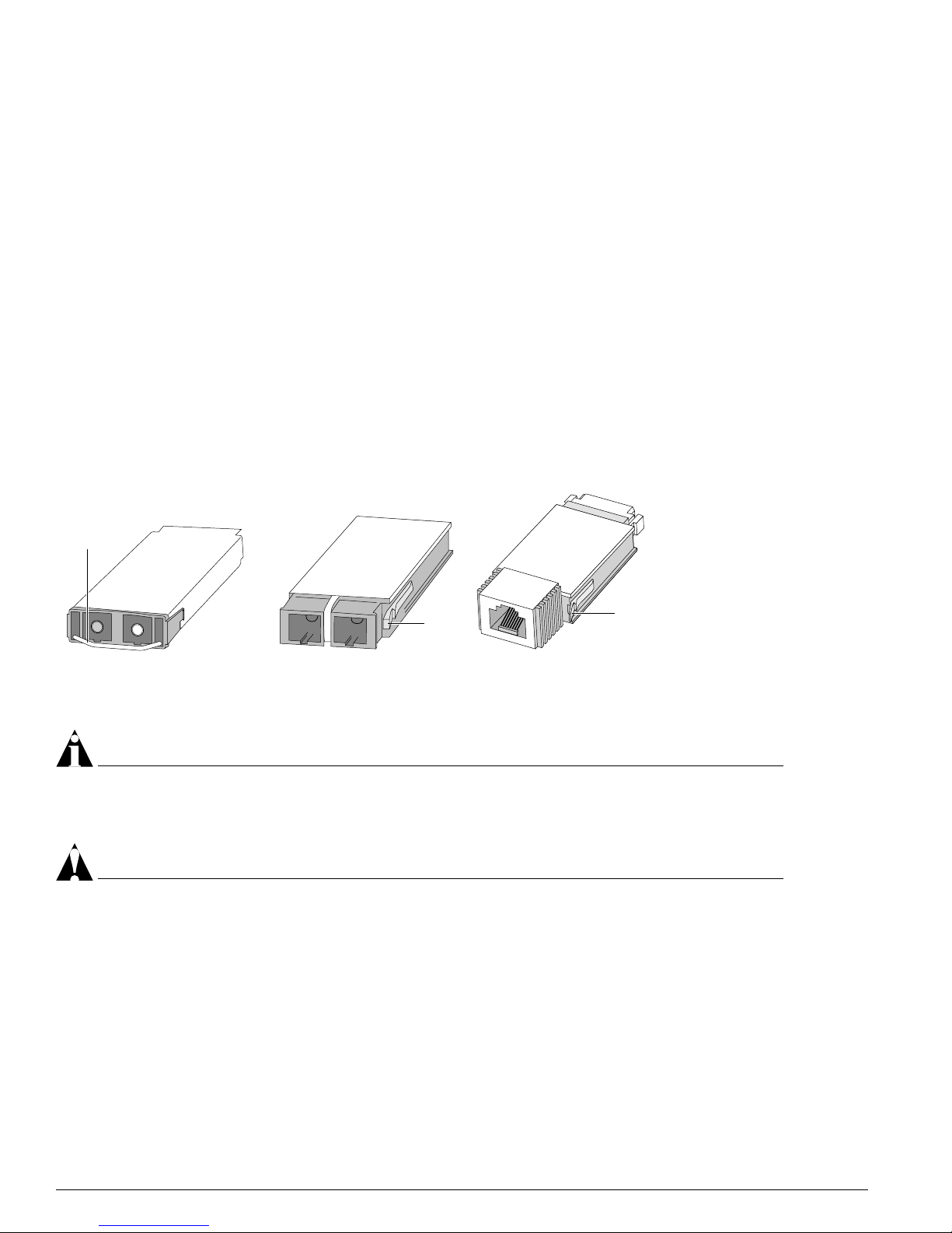
Installing or Replacing a GBIC
You ca n add and remove GBICs from your Extreme Networks switch without powering off the system.
Figure 3 shows the three types of GBIC connectors.
Figure 3: GBIC m odules
GBICs are a Cl ass 1 laser device. Us e only Ex treme-approved devices.
NOTE
Remove the SC fiber-optic or the RJ-4 5 connector from the GBIC pr ior to removing the GBIC from the
I/O module or the switch.
CAUTION
GBICs can emit invisi ble laser radiation. Avoid dir ect eye exposure to be am.
To remove a GBIC conn ector similar to the one labeled “Module A” in Figure 3, gently rotate the f ront
handle up and p ull the GBIC out of the slot.
To remove a GBIC connector similar to one labeled “Module B” or “Module C” in Figure 3, gently
squeeze the sides to release the GBIC, and pull the GBIC out o f the slot.
EW_GBIC
Module A Module B Module C
Handle
Tab
Tab
 Loading...