

Page 1

Summit Switch
Installation and User
Guide
Extreme Networks, Inc.
10460 Bandley Drive
Cupertino, California 95014
(888) 257-3000
http://www.extremenetworks.com
Published: June 1998
Part number: 100000-0 0 rev.B
Page 2

Copyright © Extreme Networks, Inc., 1998. All rights reserved. No part of this documentation may be
reproduced in any form or by any means or used to make any derivative work (such as translation,
transformation, or adaptation) without permission from Extreme Networks, Inc.
Extreme Networks, ExtremeWare, Summit, SummitLink, ExtremeWare Vista,Summit Virtual Chassis,
and the Extreme Networks logo are trademarks of Extreme Networks.
PACE is a trademark of 3Com Corporation. 3Com is a registered trademark of 3Com Corporation. All
other brand and product names are registered trademarks or trademarks of their respective holders.
ii
Page 3

Contents
Introduction xvii
Terminology xviii
Conventions xviii
Related Publications xix
UMMIT OVERVIEW
1S
About the Summit Family of S witches 1-1
Summit Switch Models 1-2
Summary of Fea tures 1-2
Port Connections 1-3
Media Types and Distanc es 1-4
Full-Duplex 1-5
Port Redundancy 1-5
Load Sharing 1-6
Virtual LANs (VLANs) 1-6
Spanning Tree Protocol (STP) 1-6
Quality of Service (QoS) 1-7
IP Unicast Routing 1- 7
IP Multicast Routing 1-7
Network Configuration Exam ple 1-8
Summit1 Front View 1-10
Summit2 Front View 1-11
Summit3 Front View 1-12
Summit4 Front View 1-13
Summit4/FX Front View 1-14
iii
Page 4

Summit48 Front View 1-15
LEDs 1-16
Summit Rear View 1-17
Power Socket 1-17
Serial Number 1-17
Console Port 1-17
Redundant Power Supply Port 1-17
MAC Address 1-18
Factory Defaults 1-18
NSTALLATION AND SETUP
2I
Following Safety Inform ation 2-1
Determining the Switch Location 2-1
Media Types and Distanc es 2-2
Installing the Summi t 2-3
Rack Mounting 2-3
Free-Standing 2-4
Stacking the Switch and Other Devices 2-4
Connecting Equipment to the Console Port 2-4
Powering On the Switch 2-6
Checking the Installation 2-6
Logging In for the First Time 2-6
CCESSING THE SWITCH
3A
Understanding the Command Syntax 3-2
Syntax Helper 3-2
Command Completion with Syntax Helper 3-2
Abbreviated Syntax 3-3
Command Shortcuts 3-3
Numerical Ranges 3-3
Names 3-3
Symbols 3-4
Line-Editing Keys 3-5
Command History 3-5
Common Commands 3-6
iv
Page 5

Configuring Management Access 3-8
Default Accounts 3-9
Changing the Default Pa ssword 3-9
Creating a Management Account 3-10
Viewing Switch Accounts 3- 10
Deleting a Switch Account 3-11
Methods of Managing th e Summit 3-11
Using the Console Interface 3-11
Using Telnet 3-12
Connecting to Another Host Using Telnet 3-12
Configuring Switch IP Parameters 3-12
Using a BOOTP Server 3-12
Manually Configuring the IP Settings 3-13
Disconnecting a Telnet Session 3-15
Disabling Telnet Access 3-15
IP Host Configuration Com mands 3-16
Using ExtremeWare Vista 3-17
Disabling Web Access 3-17
Using SNMP 3-18
Accessing Switch Agents 3- 18
Supported MIBs 3-18
Configuring SNMP Settings 3-19
Displaying SNMP Settin gs 3-21
Resetting and Disablin g SNMP 3-21
Checking Basic Connectivity 3-22
Ping 3-22
Traceroute 3-22
Mtrace 3-23
v
Page 6

ONFIGURING PORTS
4C
Enabling and Disabling Ports 4-1
Configuring Port Speed and Duplex Setting 4-2
Turning Off Autonegotiation for a Gigabit Ethernet Port 4-2
Port Commands 4-3
Load Sharing 4-5
Configuring Load Sharing 4-6
Verifying the Load S haring Configurati on 4-8
Port-Mirroring 4-8
Port-Mirroring Commands 4-9
Port-Mirroring Example 4-9
Summit Virtual Chassis 4-10
Summit Switch Port Connections 4-10
Extreme Discovery Protocol 4-11
Summit Virtual Chassis Commands 4-12
Configuring the Summit for User with the Summit Virtual
Chassis 4-12
VLANs and Summit Switches Usin g the Virtual Chassis 4-13
IRTUAL
5V
Overview of Virtual LANs 5-1
Types of VLANs 5-2
LANS (VLANS)
Benefits 5-1
Port-Based VLANs 5-2
Spanning Switches with Port-Based VLANs 5-3
Tagged VLANs 5-5
Uses of Tagged VLANs 5-6
Assigning a VLAN Tag 5-6
Mixing Port-Based and Tagged VLANs 5-8
Generic VLAN Registration Protocol 5-8
GVRP Commands 5-10
Protocol-Based VLANs 5-11
Predefined Protocol Filters 5-12
Defining Protocol Filte rs 5-12
Deleting a Protocol Filter 5-13
Precedence of Tagged Packets Over Protocol Filters 5-13
vi
Page 7

VLAN Names 5-13
Default VLAN 5-14
Configuring VLANs on the Summit 5- 14
VLAN Configuration Examples 5-16
Displaying VLAN Settings 5-17
Deleting VLANs 5-1 8
WITCH FORWARDING DATABASE
6S
Overview of the FDB 6-1
FDB Conten ts 6-1
FDB Entry Typ es 6-1
How FDB Entries Get Added 6-2
Associating a QoS Profile with an FDB Entry 6-3
Configuring FDB Entries 6-3
FDB Configuration Examples 6-4
Displaying FDB Entries 6-5
Removing FDB Entries 6-6
PANNING TREE PROTOCOL
7S
Overview of the Spanning Tree Protocol 7-1
Spanning Tree Domains 7-1
Defaults 7-2
STP Configurations 7-2
Configuring STP on the Summit 7-5
Configuration Example 7-7
Displaying STP Settings 7-8
Disabling and Resetting STP 7-9
(STP)
(FDB)
vii
Page 8

UALITY OF SERVICE
8Q
Overview of Quality of Service 8-1
Building Blocks 8-1
QoS Mode 8-2
Default QoS Profiles 8-2
Traffic G roupings 8-3
Ingress Traffic Groupings 8-3
Egress Traffic Groupings 8-5
Precedence 8-5
Prioritization 8-6
Creating and Configuring a QoS P rofile 8-6
Assigning a QoS Profile 8-6
Port Queue Monitor 8-7
Configuring QoS 8-8
Sample Ingress Mode QoS Configu ration 8-9
Sample Egress Mode QoS Config uration 8-9
Displaying QoS Informa tion 8-10
Resetting QoS 8-10
(QOS)
viii
9IP U
NICAST ROUTING
Overview of IP Unicast Routing 9-1
Router Interfaces 9-2
Populating the Routing Table 9-3
Dynamic Routes 9-3
Static Routes 9-3
Multiple Routes 9-4
Proxy ARP 9-4
ARP-Incapable Devices 9-4
Proxy ARP Between Subnets 9-5
IP Multinetting 9-5
IP Multinetting Operation 9-6
IP Multinetting Examples 9-7
Configuring IP Unicast Rou ting 9-9
Verifying the IP Unica st Routing Configuration 9-10
Configuring DHCP/BOOTP Relay 9-10
Verifying the DHCP /BOOTP Relay Configuration 9-11
Routing Configuration Example 9-15
Page 9

Displaying Router Setti ngs 9-17
Resetting and Disabling R outer Settings 9-18
10 R
OUTING PROTOCOLS
Overview 10-1
RIP Versus OSPF 10-2
Overview of RIP 10-3
Routing Table 1 0-3
Split Horizon 10-3
Poison Reverse 10-3
Triggered Updates 10-4
Route Advertisement of VLANs 10-4
RIP Version 1 versus RIP Version 2 10-4
Overview of OSPF 10-5
Link State Database 10-5
Areas 10-5
Area 0 10-6
Stub Areas 10- 6
Vi r t u a l Li nks 1 0 -7
Configuring RIP 10-8
RIP Configuration Example 10-10
Displaying RIP Settings 10 -12
Resetting and Disablin g RIP 10-13
Configuring OSPF 10-14
OSPF Configuration Example 10-16
Configuration for ABR1 10-17
Configuration for IR1 10-18
Displaying OSPF Settin gs 10-18
Resetting and Disablin g OSPF Settings 10-19
ix
Page 10

11 IP M
ULTICAST ROUTING
Overview 11-1
DVMRP Overview 11-2
IGMP Overview 11-2
IGMP Snooping 11-2
Configuring IP Multicasti ng Routing 11-2
Configuration Example 11-6
Configuration for IR1 11-7
Displaying IP Multicast R outing Settings 11-7
Deleting and Resetting IP M ulticast Settings 11-8
12 S
TATUS MONITORING AND STATISTICS
Status Monito ring 12-1
Port Statistics 12-7
Port Errors 12-8
Port Monitoring Display K eys 12-9
Switch Logging 12-10
Local Logging 12-11
Real-time Display 12-11
Remote Logging 12-12
Logging Commands 12-12
RMON 12-14
About RMON 12-14
RMON Features of the Switch 12-15
Statistics 12-15
History 12-15
Alarms 12-16
Events 12-16
RMON and the S witch 12-16
Event Actions 12-17
x
Page 11

13 U
SING EXTREMEWARE VISTA
Enabling and Disabling Web Access 13-1
Setting Up You r Browser 13 -2
Accessing ExtremeWare Vista 13-3
Navigating ExtremeWare Vista 13-3
Task Frame 13-4
Content Frame 13-4
Browser Controls 13-4
Status Messages 13- 5
Standalone Buttons 13-5
Saving Changes 13-5
Do a GET When Conf iguring a VLAN 13 -6
Sending Screen Output to Extreme Networks 13-6
14 S
AS
BT
OFTWARE UPGRADE AND BOOT OPTIONS
Downloading a New Imag e 14-1
Rebooting the Switch 14-2
Saving Configurati on Changes 14-3
Returning to Factory Defaults 14-3
Using TFTP to Upload the Configura tion 14-4
Using TFTP to Download the Con figuration 14-4
Boot Option Commands 14-5
AFETY INFORMATION
Important Safety Information A-1
Power A-1
Power Cord A-2
Fuse A-3
Connections A-3
Lithium Battery A-4
ECHNICAL SPECIFICATIONS
xi
Page 12

ROUBLESHOOTING
CT
LEDs C-1
Using the Command-Line Interface C-2
VLANs C-4
STP C-5
NDEX
I
NDEX OF COMMANDS
I
xii
Page 13

Figures
1-1 Dual-homing configura tion 1-5
1-2 Network configuration usin g the Summit famil y of
switches 1-8
1-3 Summit1 front view 1-10
1-4 Summit2 front view 1- 11
1-5 Summit3 front view 1-12
1-6 Summit4 front view 1-13
1-7 Summit4/FX front view 1-14
1-8 Summit48 front view 1-15
1-9 Summit rear view 1-17
2-1 Fitting the mounting bracket 2-3
2-2 Null-modem cable pin-outs 2-5
2-3 PC-AT s erial null-modem cable pin-outs 2-5
5-1 Example of a port-based VLAN 5-3
5-2 Single port-based VLAN spanning two switches 5-4
5-3 Two port-based VLANs spanning two Switches 5-5
5-4 Physical diagram of tagged and untagged traffic 5-7
5-5 Logical diagram of tagged and untagged traffic 5-7
5-6 Network example using GVRP 5- 9
5-7 Protocol-based VLANs 5-11
7-1 Multiple Spanning Tree Domains 7-3
7-2 Tag-based STP co nfiguration 7-4
9-1 Routing between VLANs 9-2
9-2 Unicast routing configuration example 9-16
10-1 Stub area 10-6
10-2 Virtual link for stub area 10-7
xiii
Page 14

10-3 Virtual link providing redundancy 10-7
10-4 RIP configuration example 10-11
10-5 OSPF configuration example 10-16
11-1 IP multicast routing configuration example 11-6
xiv
Page 15

Tables
1 Notice Icons xviii
2 Text Conventions xviii
1-1 Summit Switch Port Conf igurations 1-3
1-2 Media Types and Distanc es 1-4
1-3 Summit LEDs 1-16
1-4 Summit Factory Defaults 1- 18
2-1 Media Types and Distanc es 2-2
2-2 Console Connector Pin-Outs 2-5
3-1 Command Syntax Symbols 3-4
3-2 Line-Editing Keys 3-5
3-3 Common Commands 3-6
3-4 Default Accounts 3-9
3-5 IP Host Configuration Com mands 3-16
3-6 Supported MIBs 3-18
3-7 SNMP Configura tion Command s 3-20
3-8 SNMP Reset and Disable Commands 3-21
3-9 Ping Command Parameters 3-22
4-1 Port Commands 4-3
4-2 Port Combinations f or the Summit1 4-6
4-3 Port Combinations f or the Summit2 4-6
4-4 Port Combinations f or the Summit3 4-6
4-5 Port Combinations f or the Summit4 and Summ it4/FX 4-7
4-6 Port Combinations for the Sum mit48 4-7
4-7 Port-Mirroring Configuration Comman ds 4-9
4-8 Summit Ports to Use to Connect to th e Summit Virtual
Chassis 4-10
xv
Page 16

4-9 Summit Virtual Chassis Commands 4-12
5-1 GVRP Commands 5-10
5-2 VLAN Configuration Commands 5-14
5-3 VLAN Delete and Reset Commands 5-18
6-1 FDB Configuration Comma nds 6-3
6-2 Removing FDB Entry Commands 6-6
7-1 STP Configuration Comma nds 7 -6
7-2 STP Disable and Reset Commands 7-9
8-1 Default QoS Profiles 8-3
8-2 802.1p Va lues and Associated QoS Profiles 8-4
8-3 PQM Commands 8-7
8-4 QoS Configuration Commands 8-8
9-1 Basic IP Commands 9-11
9-2 Route Table Configuration Commands 9-13
9-3 ICMP Configuration Commands 9-14
9-4 Router Show Commands 9-17
9-5 Router Reset and Disable Commands 9-18
10-1 RIP Configuration Commands 10-8
10-2 RIP Show Commands 10-12
10-3 RIP Reset and Disable Commands 10-13
10-4 OSPF Configuration Comman ds 10-14
10-5 OSPF Show Comma nds 10-18
10-6 OSPF Reset and Disable Commands 10-19
11- 1 IP Multicast Routing Config uration Commands 11-3
11- 2 IGMP Configuration Commands 11-4
11-3 IP M ulticast Routing Show Commands 11-7
11- 4 IP Multicast Routing Reset and Disa ble Commands 11-8
12-1 Switch Monitoring Commands 12-1
12-2 Port Monitoring D isplay Keys 12-9
12-3 Fault Levels Assigned by the Switch 12-10
12-4 Fault Log Subsystems 12-10
12-5 Logging Commands 12- 13
12-6 Event Actions 12-17
13-1 Multi-Select List Box Key Definitions 13-4
14-1 Boot Option Commands 14-5
xvi
Page 17

Preface
This Preface provides an overview of this guide, describes guide conventions, and lists
other publications that may be useful.
NTRODUCTION
I
This guide provides the required information to install and configure the Summit
Family of Gigabit Ethernet Switches.
This guide is intended for use by network administrators who are responsible for
installing and setting up network equi pment. It assumes a basic working k nowledge of
• Local Area Networks (LANs)
• Ethernet concepts
• Ethernet switching and bridging concepts
• Routing concepts
• Simple Network Management Protocol (SNMP)
If the information in the Release Notes shippe d with your switch differs from the
information in this gu ide, follow the Release Notes.
UMMIT SWITCH INSTALLATION AND USER GUIDE XVII
S
Page 18

REFACE
P
ERMINOLOGY
T
When features, functionality, or operation is specific to a particular model of the
Summit family, the model name is used (for example, Summit1 or Summit4).
Explanations about features and operations that are the same among all members of the
Summit family simply refer to the product as the Summit.
ONVENTIONS
C
Table 1 and Table 2 list conventions that are used throughout this guide.
Table 1:
Icon Notice Type Alerts you to...
Table 2:
Convention Description
Screen displays
The words “enter”
and “type”
[Key] names Key names appear in text in one of two ways:
Notice Icons
Note Important features or instructions.
Caution Risk of personal injury, system damage,
Warning Risk of severe personal injury.
or loss of dat a.
Text Conventions
This typeface represents information as it appears on the screen
When you see t he word “en ter” in th is guide, y ou must type
something, and then press the Return or Enter key. Do not press the
Return or Enter key when an in struction simply says “ type.”
■
Referred to by their labels, such as “the Return key” or “the
Escape key”
■
Written with brackets, such as [Return] or [Esc]
If you must press two or more keys simultaneously, the key names
are linked with a plus sign (+). Example:
Press [Ctrl]+[Alt]+[Del].
.
XVIII
UMMIT SWITCH INSTALLATION AND USER GUIDE
S
Page 19

ELATED PUBLICATIONS
R
Table 2:
Convention Description
Words in
Text Conventions (continued)
italicized
type Italics emphasize a point or denote new terms at the place where
they are defined in the text.
The command syntax is explained in Chapter 3.
ELATED PUBLICATIONS
R
The Summit documentation s et includes the following:
• Summit Quick Reference Guide
• Summit Release Notes
You may f ind the following Web site of interest:
• Extreme Networks Home Page: http://www.extremenetworks.com/
UMMIT SWITCH INSTALLATION AND USER GUIDE XIX
S
Page 20

REFACE
P
XX
UMMIT SWITCH INSTALLATION AND USER GUIDE
S
Page 21

1
Summit Overview
This chapter describes the following:
• Summit switch models
• Summit feat ures
• How to use the Summit famil y of switches in your netw ork configuration
• Summit front views
• Summit rear view
• Summit LEDs
• Factory default settings
BOUT THE SUMMIT FAMILY OF SWITCHES
A
Network managers are currently faced with the challenge of creating networks that can
provide ultra-fast speed and high performance to serve the needs of today’s network
users, while simultaneously preserving the investment they have made in Ethernet and
Fast Ethernet tech nology.
By addressing the entire spectrum of Ethernet data rates (10/100/1000 Mbps), the
Summit family of LAN switches enables you to introduce high-speed Gigabit Ethernet
backbones into your exist ing network, w hile maintaining established connecti ons to the
10 Mbps and 100 Mbps segments that already exist.
UMMIT SWITCH INSTALLATION AND USER GUIDE
S
1-1
Page 22

UMMIT OVERVIEW
S
UMMIT SWITCH
S
The Summit family of switches i s comprised of six models, as fo llows:
• Summit1
• Summit2
• Summit3
• Summit4
• Summit4/FX
• Summit48
UMMARY OF FEATURES
S
Summit switches support the f ollowing features:
• Fully nonblocking opera tion
— All ports transmit a nd receive packets at wire speed
• Optional redundant power supply
• 128K addresses in the switch forwarding database in bridging mode
• Redundant physical Gigabit Et hernet backbone connection
M
ODELS
• Autonegotiation for half- or full-duplex operation (Fast Ethernet ports, only)
• Load-sharing on multiple ports
• Virtual local area networks (VLANs) including suppo rt for 802.1Q
• Spanning Tree Protocol (STP) (IEEE 802.1D) with multiple STP domains
• Policy-based Quality of Service (QoS)
• Wire-speed Internet Protocol (IP) routing
• IP Multinetting using the Intern et Group Multicast Protocol (IGMP)
• DHCP/BOOTP Relay
• Routing Information Protocol (RIP) version 1 and RIP version 2
• Open Shortest Path First (OSPF) routing protocol
• Wire-speed IP multicast routing support
• IGMP snooping to control IP multicast traffic
1-2 S
UMMIT SWITCH INSTALLATION AND USER GUIDE
Page 23

UMMARY OF FEATURES
S
• Distance Vector Multicast Routing Protocol (DVMRP)
• Console command line interface (CLI) connection
• Telnet CLI connection
™
• ExtremeWare
Vi s t a™ Web-based management interface
• Simple Network Management Protocol (SNMP) support
ORT CONNECTIONS
P
The major difference between the models of the Summit switch is the port
configurations on each switch model. Summit switches use a combination of the
following types of ports:
• Fixed 1000BASE-SX ports using 850nm duplex SC connectors
• Modular 1000BASE-LX and 1000BASE-LX10 using Gigabit Interface Connectors
(GBICs)
• 10BASE-T/100BASE-TX ports using standard RJ-45 connectors
• 100BASE-FX ports using st andard SC connectors
Table 1-1 describes port configurations available on the different Summit switch models.
Table 1-1:
Switch Model
Summit1 6 2
Summit2 2 1 16
Summit3 1 1 24
Summit4 6 16
Summit4/FX 6 16
Summit48 2 2 48
Summit Switch Port Con figurations
Gigabit Ethernet Ports
Fixed
1000BASE-SX GBIC
Redundant
GBIC
10BASE-T/
100BASE-TX 100BASE-FX
UMMIT SWITCH INSTALLATION AND USER GUIDE
S
1-3
Page 24

UMMIT OVERVIEW
S
M
EDIA TYPES AND DISTANCES
Table 1-2 describes the media types and distances for the different types of Summit
ports.
Table 1-2:
Standard Media Type
1000BASE-SX 50/125um Multimode Fiber
1000BASE-LX 50/125um Multimode Fiber
Media Types and Distances
50/125um Multimode Fiber
62.5/125um Multimode Fiber
62.5/125um Multimode Fiber
50/125um Multimode Fiber
62.5/125um Multimode Fiber
10u Single-mode Fiber
Mhz/Km
Rating
400
500
160
200
400
500
500
Maximum
Distance
500 Meters
550 Meters
220 Meters
275 Meters
550 Meters
550 Meters
550 Meters
5,000 Mete rs
1000BASE-LX10* 10u Single-mode Fiber 10,000 Meters
100BASE-FX 50/125um Multimode Fiber
400 Meters
(half-duplex operation
50/125um Multimode Fiber
2000 Meters
(full-duplex operation)
62.5/125um Multimode Fiber
400 Meters
(half-duplex operation)
52.5/125um Multimode Fiber
2000 Meters
(full-duplex operation)
100BASE-TX
10BASE-T
Category 5 UTP Cable (100Mbps)
Category 3 UTP Cable (10Mbps)
100 Meters
100 Meters
XTREME NETWORKS PROPRIETARY
*E
OF
5,000 M
ETERS
.
. CAN BE
CONNECTED TO
1000BASE-LX ON
SINGLE-MODE FIBER USING A MAXIMUM DISTANCE
For more information on 1000B ASE-SX and 1000B ASE-LX link character istics,
refer to IEEE Draft P802.3z/D4.2, Ta ble 38-2 and Table 38-6.
1-4 S
UMMIT SWITCH INSTALLATION AND USER GUIDE
Page 25

UMMARY OF FEATURES
S
ULL-DUPLEX
F
The Summit switch provides full-duplex support for all ports. Fu ll-duplex allows
frames to be transmitted and received simultaneously and, in effect, doubles the
bandwidth av ailable on a l ink. All 10 /100 Mbps p orts on the S ummit auton egotiate fo r
half- or full-duplex operation.
ORT REDUNDANCY
P
The Summit2, Summit3, and Summit48 have an optional redundant Gigabit Ethernet
port. Using the redundant port, you can dual-home these models to one or two
switches. Figure 1-1 illustrates a Summit2 dual-homed to two different switches.
Dual-homed
Active
Figure 1-1:
Backup
Dual-homing confi guration
In the event that the active port fails or loses link status, the redundant port is
automatically activated. When the primary port resumes operation, the redundant port
becomes inactive. This feature can be disabled.
The redundant port cannot be used for load sharing when the primary port is active. If
the primary port becomes inactive, the redundant port is activated in the load sharing
configuration.
UMMIT SWITCH INSTALLATION AND USER GUIDE
S
1-5
Page 26
UMMIT OVERVIEW
S
OAD SHARING
L
Load sharing with Summi t switches allows the user to increase bandwidth and
resilience between switches by using a group of ports to carry traffic in parallel between
switches. The sharing algorithm a llows the switch to use mu ltiple ports as a single
logical port. For example, VLANs see the load-sharing group as a single virtual port.
The algorithm also guarantees packet sequencing between clients.
For information on load shar ing, refer to Chapter 4.
IRTUAL
V
LANS (VLANS)
The Summit has a VLAN feature that enables you to const ruct your broadcast domains
without being restricted by physical conn ections. Up to 255 VLANs can be defined on
the Summit. A VLAN is a group of location- and topology-independent devices that
communicate as if they were on the same physica l local area network (LAN).
Implementing VLAN s on your networ k has the followin g three advantages :
• It helps to control broadcast traffic. If a device in VLAN marketing transmits a
broadcast frame, only VLAN marketing devices receive the frame.
• It provides extra security. Devices in VLAN marketing can only communicate with
devices on VLAN sales using a device that provides routing services.
• It eases the change and movement of devices on networks. If a device in VLAN
marketing is moved to a port in another part of the network, all you must do is
specify that the new port belongs to VLA N marketing.
For more infor mation on VLANs, refer to Chapter 5.
PANNING TREE PROTOCOL
S
(STP)
The Summit supports the IEEE 802.1D Spanning Tree Protocol (STP), which is a
bridge-based mechanism for providing fault tolerance on ne tworks. STP enables you to
implement parallel paths for ne twork traffic, and ensure the following:
• Redundant paths are disabled when the main paths are operational.
• Redundant paths are enabled if the main traffic paths fail.
1-6 S
UMMIT SWITCH INSTALLATION AND USER GUIDE
Page 27
UMMARY OF FEATURES
S
The Summit supports up to 64 Spann ing Tree Domains ( STPDs).
For more information on STP, refer to Chapter 7.
UALITY OF SERVICE
Q
(QOS)
The Summit has policy-based Qual ity of Service (QoS) features that enable you to
specify service levels for different traffic groups. By default, all traffic is assigned with
the “normal” QoS policy profile. If needed, you can create other QoS policies and apply
them to different traffic types so that they have different guaranteed minimum
bandwidth, maximum bandwidth, and priority.
For more information on Qualit y of Serv ice, refer to Chapter 8.
NICAST ROUTING
IP U
The Summit can route IP traffic between the VLANs that are configured as virtual
router interfaces. Both dynamic and static IP routes are maintained in the routing table.
The following routing protocols are supported:
• RIP version 1
• RIP version 2
• OSPF
For more information on IP uni cast routing, refer to Cha pter 9.
ULTICAST ROUTING
IP M
The Summit can use IP multicastin g to allow a single IP hos t to transmit a packet to a
group of IP hosts. The Summit supports statically configured IP multicast routes, and
multicast routes that are learned by way of the D istance Vector Multica st Routing
Protocol (DVMRP).
For more information on IP multicast rou ting, refer to Chapter 11.
UMMIT SWITCH INSTALLATION AND USER GUIDE
S
1-7
Page 28
UMMIT OVERVIEW
S
ETWORK CONFIGURATION EXAMPLE
N
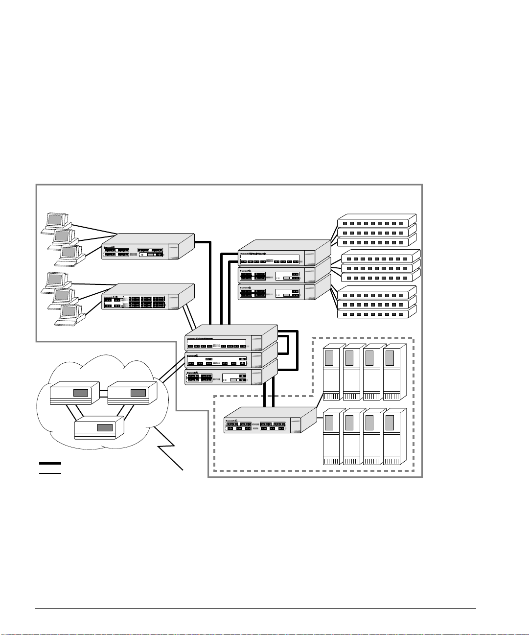
As shown in Figure 1-2 , the family of Summit switches offer a unique end-to-end LAN
system solution. From the desktop, to the gigabit core, to the data center/server farm,
there are Summit switches with an optimized hardware configuration to match the
requirements. ExtremeWare software is common to all Summit switches, and allows for
the same services to operate across the entire product family. All Summit switches
deliver wire-speed throughput and end-to-end policy based Quality of Service.
Intranet Switching Architecture
Gigabit
10/100 Mbps
Figure 1-2:
Desktop switches
Desktop switches
Routers
Segment switches
Data Center
Integrated Server switch
L2/L3
Network configuration usi ng the Summit family of switches
1-8 S
UMMIT SWITCH INSTALLATION AND USER GUIDE
Page 29

ETWORK CONFIGURATION EXAMPLE
N
In the gigabit core of the network, the Sum mit1 and Summit2 act as a ggregators of
Gigabit Ethernet links from the edge and data center switches, as well as Ethernet and
Fast Ethernet links from legacy routers and hubs. In the core of the network, the
Summit1 and Summit2 ca n scale in port density and performa nce by connecting to a
Summit Virtual Chassis to support up to 32 non- blocking Gigabit Ethernet po rts at 48
million packets per second (pps), or 128 non-blocking 10/100BASE-TX ports at 19
million pps.
In the data center or server farm, the Summit4 offers the right mix of ports and features
for servers. Data centers and server farms require integrated wire-speed routing to
eliminate the performance penalty associated with legacy routers when servers had to
be separated into different subnets. In addition, the Summit4 supports trunking of
either Ethernet, Fast Ethernet, or Gigabit Ethernet ports to match the performance of the
LAN connection to the performance of the server. The goal is to only buy the amount of
bandwidth that is needed and can be used. This is ideal for servers that can drive 400
Mbps on trunk Fast Ethernet ports, but would not be capable of more than 400 Mbps
performance on a Gigabit Ethernet port. The port density and performance of the
Summit4 can be scaled with the Summit Virtual Chassis to 16 Gigabit Ethernet ports,
and 128 10/100BASE-T X ports at 43 million pps.
At the edge of the network, higher-performance desktops need dedicated throughput,
while other devices can use small, shared segments. For higher-performance
connections, use the Summit3 and Summit48 switches (which offer 24 10/100BASE-TX
ports) and a single Gigabit Ethernet port, or 48 10/100BASE-TX ports and two Gigabit
Ethernet ports, respectively. For shared desktop segments, the Summit2 offers 16
10/100BASE-TX ports and two Gigabit Ethernet ports. Combining the Summit3 and the
Summit48 with the Summi t Virtual Chassis, desktop switching port densities can scale
to 192 10/100BASE-TX ports at 28 million pps, and 384 10 /100BASE-TX ports at 28
million pp s, respe ctively.
UMMIT SWITCH INSTALLATION AND USER GUIDE
S
1-9
Page 30
UMMIT OVERVIEW
S
UMMIT
S
RONT VIEW
1 F
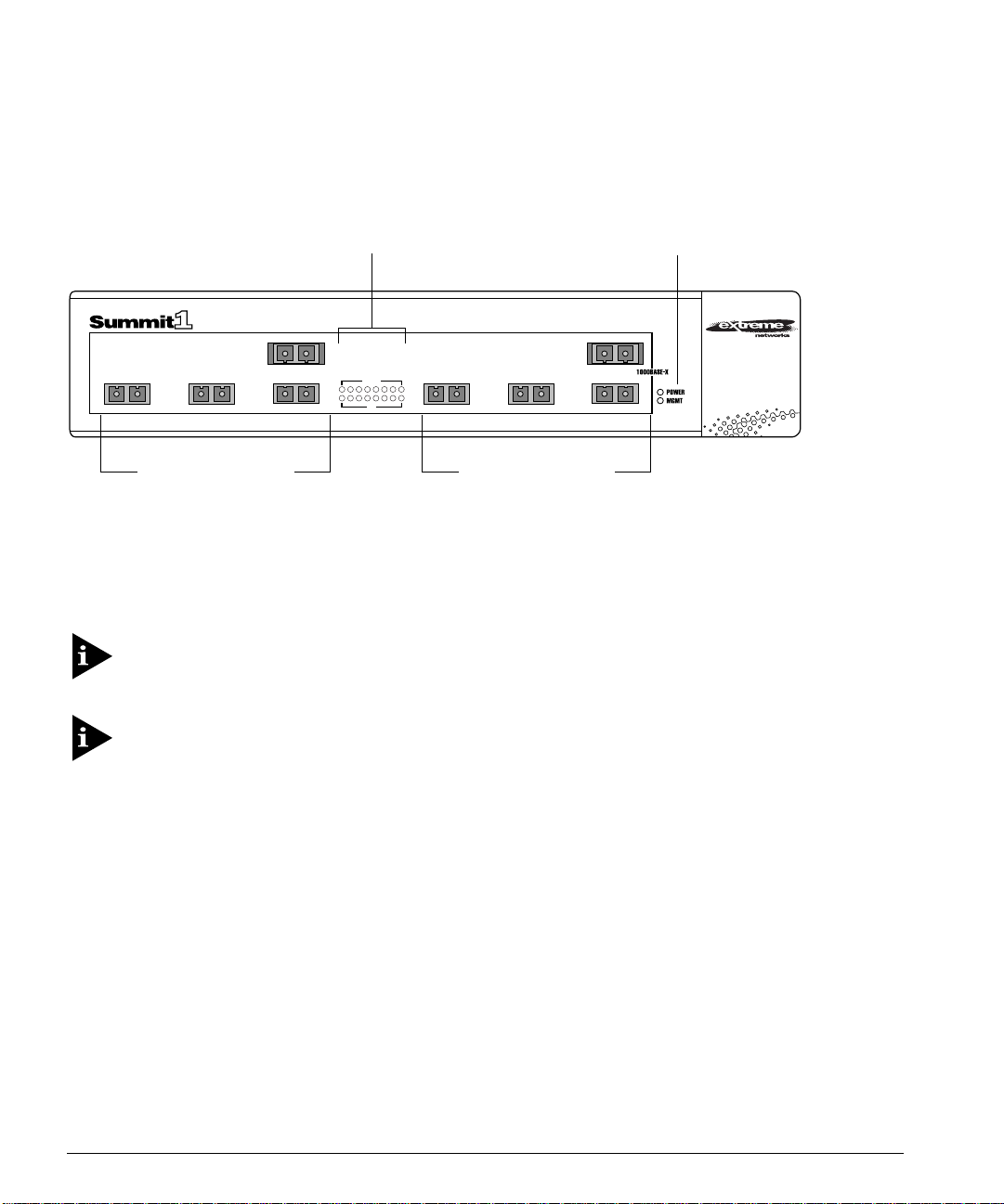
Figure 1-3 shows the Summit1 front view.
Gigabit Ethernet ports
Figure 1-3:
Port status LEDs
1
32
4
Summit1 front view
AMBER
=
ACTIVITY
GREEN
=
LINK OK
FLASHING GREEN
=
DISABLED
ACTIVITY
12345678
910111213141516
LINK
65
Gigabit Ethernet ports
Unit status LEDs
8
7
The Summit1 has eight Gigabit Ethernet ports. Six of the ports use SC connectors and
support 1000BASE-SX over multimode fiber-optic cable. Ports 1 and 8 use modular
GBIC connectors.
For information on suppor ted media types a nd distances, refer to Table 1-2.
For information on Summit LEDs, refer to “LEDs,” on page 1-16.
1-10 S
UMMIT SWITCH INSTALLATION AND USER GUIDE
Page 31

UMMIT
S
RONT VIEW
2 F
UMMIT
S
RONT VIEW
2 F
Figure 1-4 shows the Summit2 front view.
10/100 Mbps ports
Figure 1-4:
4321
1211109
8765
16151413
Summit2 front view
Port status LEDs
AMBER
=
ACTIVITY
GREEN
=
LINK OK
FLASHING GREEN
=
DISABLED
12345678
910111213141516
Gigabit Ethernet ports
Unit status LEDs
18
1717R
The Summit2 has 16 auto sensing 10BASE-T/1 00BASE-TX ports and two G igabit
Ethernet ports, one of which has a redundant Gigabit Ethernet port.
For information on suppor ted media types a nd distances, refer to Table 1-2.
For information on Summit LEDs, refer to “LEDs,” on page 1-16.
UMMIT SWITCH INSTALLATION AND USER GUIDE
S
1-11
Page 32

UMMIT OVERVIEW
S
UMMIT
S
RONT VIEW
3 F
Figure 1-5 shows the Summit3 front view.
Unit status LEDs
10/100 Mbps ports
1234 5678
9 101112 13141516
10/100 Mbps ports
Figure 1-5:
Summit3 front view
AMBER
GREEN
FLASHING GREEN
12345678
9101112131415 16
17 18 19 20 21 22 23 24
17 18 19 20 21 22 23 24
=
ACTIVITY
=
LINK OK
=
DISABLED
25 25
ACTIVITY
25
25
LINK
R
Gigabit Ethernet portsPort status LEDs
2525R
The Summit3 has 24 autosensing 10BASE-T/100BASE-TX ports, one Gigabit Ethernet
port, and one redundant Gigabit Ethernet port.
For information on suppor ted media types a nd distances, refer to Table 1-2.
For information on Summit LEDs, refer to “LEDs,” on page 1-16.
1-12 S
UMMIT SWITCH INSTALLATION AND USER GUIDE
Page 33

UMMIT
S
RONT VIEW
4 F
UMMIT
S
RONT VIEW
4 F
Figure 1-6 shows the Summit4 front view.
1234 5678
17
Gigabit Ethernet ports
Figure 1-6:
Summit4 front view
Port status
LEDs
AMBER
=
ACTIVITY
GREEN
=
LINK OK
FLASHING GREEN
=
DISABLED
12345678
91011121314
15 16
ACTIVITY
17 18 19 20 21 22
17 18 19 20 21 22
LINK
10/100 Mbps ports10/100 Mbps ports
9 101112 13141516
21
Gigabit Ethernet ports
Unit status LEDs
22201918
The Summit4 has 16 autosensing 10BASE-T/100BASE-TX ports and 6 Gigabit Ethernet
ports. The Gigabit Ethernet ports use standard SC connectors and support 1000BASE-SX
over multimode fiber-optic cable.
For information on suppor ted media types a nd distances, refer to Table 1-2.
For information on Summit LEDs, refer to “LEDs,” on page 1-16.
UMMIT SWITCH INSTALLATION AND USER GUIDE
S
1-13
Page 34

UMMIT OVERVIEW
S
UMMIT
S
4/FX F
RONT VIEW
Figure 1-7 shows the Summit4/FX front view.
100 Mbps ports
1234
9 101112
Gigabit Ethernet ports
Figure 1-7:
Summit4/FX front view
321
Port status
LEDs
FLASHING AMBER
=
TRAFFIC
SOLID AMBER
=
DISABLED
GREEN
=
ENABLED, LINK OK
12345678
91011121314
15 16
LINK
123456
123456
ACTIVITY
100 Mbps ports
5678
13 14 15 16
Gigabit Ethernet ports
Unit status LEDs
654
The Summit4/FX has 16 10 0BASE-FX ports and 6 Gigabit Ethe rnet ports. All ports use
standard SC connectors. The Gigabit Ethernet ports support 1000BASE-SX over
multimode fiber-optic cable.
For information on suppor ted media types a nd distances, refer to Table 1-2.
For information on Summit LEDs, refer to “LEDs,” on page 1-16.
1-14 S
UMMIT SWITCH INSTALLATION AND USER GUIDE
Page 35

UMMIT
S
48 F
RONT VIEW
UMMIT
S
48 F
RONT VIEW
Figure 1-8 shows the Summit48 front view.
10/100 Mbps ports
1234 5678 9101112
22 23 24
13
=
=
=
DISABLED
ACTIVITY
LINK OK
14 15 16 17 18 19 20 21 22 23 24
25 26 27 28 29 30 31 32 33 34 35 36
37 38 39 40 41 42 43 44 45 46 47 48
10/100
BASE-X
MDI-X
Power
Mgmt.
Unit status
LEDs
1000
BASE-X
Gigabit Ethernet
Figure 1-8:
123456
7 8 9 10 11 12
49R
13 14 15 16 17 18
49
A
49R
19 20 21
49
L
49R49
AMBER
GREEN
FLASHING GREEN
25 26 27 28 29 30
31 32 33 34 35 36
50R
A
37 38 39 40 41 42
50
50R
50
43 44 45 46 47 48
L
50R50
Port status
ports
LEDs
Summit48 front view
The Summit48 has 48 autosensing 10BASE-T/100BASE-TX ports, 2 Gigabit Ethernet
ports, and 2 redundant Gigabit Ethernet ports. All the Gigabit Ethernet ports use GBIC
connectors.
For information on suppor ted media types a nd distances, refer to Table 1-2.
For information on Summit LEDs, refer to “LEDs,” on page 1-16.
UMMIT SWITCH INSTALLATION AND USER GUIDE
S
1-15
Page 36

UMMIT OVERVIEW
S
LED
S
Table 1-3 describes the light emitting diode (LED) behavior on the Summit.
Table 1-3:
LED Color Indicates
Power Green
MGMT Green flashing
10/100Mbps Port Status LEDs
Gigabit Ethernet Port Status LEDs
Packet Yellow
Status Green on
Summit LEDs
Yellow
Slow
■
Fast
■
Yellow
Green
Yellow
Green flashing
Off
Off
Green flashing
Off
The Summit is powered up.
The Summit is indicating a power, overheat, or fan failure.
The Summit is operating normally.
Power On Self Test (POST) in progress, or software download
in progress.
The Summit has failed its POST.
Link is present; port is enabled.
Frames are being transmitted/received on this port.
Link is present; port is disabled.
Link is not present.
Frames are being transmitted/received on this port.
No activity on this port.
Link is present; port is enabled;
full-duplex operation.
Link is present; port is disabled.
Link is not present.
1-16 S
UMMIT SWITCH INSTALLATION AND USER GUIDE
Page 37

UMMIT REAR VIEW
S
Figure 1-9 shows the rear view for the Summit switch.
ULU
C
L
!
MADE IN USA
130001-00 Rev.03
MODEL/NUMBER
PART NUMBER
SERIAL NUMBER
MAC ADDRESS
UMMIT REAR VIEW
S
Console portRPS portPower socket and fuse
Figure 1-9:
OWER SOCKET
P
Summit rear view
The Summit automatically adjusts to the supply volt age. The power supply operates
down to 90 V. Th e fuse is suitab le for both 110 V AC and 220- 240 V AC oper ation.
ERIAL NUMBER
S
Use this serial number for fault-reporting purposes.
ONSOLE PORT
C
Use the console port (9-pin, “D” type connector) for connecting a terminal and carrying
out local out-of-ban d management.
EDUNDANT POWER SUPPLY PORT
R
The redundant power supply (RPS) port is used to connect to a Summit RPS or a
Summit Virtual Chassis. Both the Summit RPS and the Summ it Virtual Chassis provide
a redundant, load-shared power source to the Summit. If the primary power source for
the switch fails, the RPS in either the S ummit RPS or the Summit Virtual Chassis takes
over, ensuring uninterrupted network operation.
UMMIT SWITCH INSTALLATION AND USER GUIDE
S
1-17
Page 38

UMMIT OVERVIEW
S
In addition, when connected to a Summit R PS or Summit Virtual Chassis, the Summit
switch can provide status on power and fan operation of the RPS through SNMP, the
command-line interface, and the Web interface (power supply status only).
The Summit RPS and Summit Virtual Chassis can simultaneously provide power for as
many as two Summit s witches.
MAC A
DDRES S
This label shows the unique Ethernet MAC address assigned to this device.
ACTORY DEFAULTS
F
Table 1-4 shows factory defaults for the Summit features.
Table 1-4:
Item Default Setting
Port status Enabled on all ports.
Serial or Telnet user account
Console port configuration 9600 baud, eight data bits, one stop bit, no parity,
Web network management Enabled.
SNMP read community string public.
SNMP write community string private.
RMON history session Enabled.
RMON alarms Disabled.
BOOTP Enabled on the default VLAN (
QoS All traffic is part of the default queue in ingress mode.
802.1p priority Recognition enabled.
802.3x flow control Enabled.
Virtual LANs One VLAN named
802.1Q tagging All packets are untagged on the default VLAN (
Spanning Tree Protocol Disabled for the switch; enabled for each port in the STPD.
IP Routing Disabled.
Forwarding database aging period 30 0 seconds (5 minutes).
Summit Factory Defaults
admin
XON/XOFF flo w control enabl ed.
VLAN. The default VLAN belongs to the STPD named
with no password and
default
; all ports b elong to t he defaul t
user
with no password.
default
).
s0
default).
.
1-18 S
UMMIT SWITCH INSTALLATION AND USER GUIDE
Page 39

ACTORY DEFAULTS
F
Table 1-4:
Summit Factory Defaults (continued)
Item Default Setting
RIP Disabled for the switch; enabled on each VLAN
configured with an IP address.
OSPF Disabled for the switch; enabled for each VLAN
configured with an IP address. All VLANs belong to the
backbone area.
IP multicast routing Disabled.
DVMRP Disabled for the switch; enabled for each VLAN
configured with an IP address.
IGMP snooping Disabled.
GVRP Disabled.
UMMIT SWITCH INSTALLATION AND USER GUIDE
S
1-19
Page 40

UMMIT OVERVIEW
S
1-20 S
UMMIT SWITCH INSTALLATION AND USER GUIDE
Page 41

2
Installation and Setup
This chapter describes the following:
• How to decide where to install the Summit
• Gigabit Ethernet configuration rules
• How to install the swi tch in a rack or free-standing
• How to connect equipment to the console po rt
• How to check the installation using the Power On Self-Test (POST)
OLLOWING SAFETY INFORMATION
F
Before installing or removing any component s of the switch, or before carrying out any
maintenance procedures, you must read the safety information provided in Appendix A
of this guide.
ETERMINING THE SWITCH LOCATION
D
The Summit is suited for use in the office, where it can be free-standing or mounted in a
standard 19-inch equipment rack. Alternatively, the device can be rack-mounted in a
wiring closet or equipment room. Two mounting brackets are supplied with the switch.
UMMIT SWITCH INSTALLATION AND USER GUIDE
S
2-1
Page 42

NSTALLATION AND SETUP
I
When deciding where to install the switch, ensure that:
• The switch is accessible and cables can be connected easi ly.
• Water or moisture cannot enter the case of the unit.
• Air-flow around the unit and through the vents in the side of the case is not
restricted. You should provide a minimum of 25mm (1-inch) clearance.
• No objects are placed on top of the unit.
• Units are not stacked more than four high if the sw itch is free-standing.
EDIA TYPES AND DISTANCES
M
The connectors, media types, and maximum distances are described in Table 2-1.
Table 2-1:
Standard Media Type
1000BASE-SX 50/125um Multimode Fiber
1000BASE-LX 50/125um Multimode Fiber
Media Types and Distances
50/125um Multimode Fiber
62.5/125um Multimode Fiber
62.5/125um Multimode Fiber
50/125um Multimode Fiber
62.5/125um Multimode Fiber
10u Single-mode Fiber
Mhz/Km
Rating
400
500
160
200
400
500
500
Maximum
Distance
500 Meters
550 Meters
220 Meters
275 Meters
550 Meters
550 Meters
550 Meters
5,000 Mete rs
1000BASE-LX10* 10u Single-mode Fiber 10,000 Meters
100BASE-FX 50/125um Multimode Fiber
400 Meters
(half-duplex operation
50/125um Multimode Fiber
2000 Meters
(full-duplex operation)
62.5/125um Multimode Fiber
400 Meters
(half-duplex operation)
52.5/125um Multimode Fiber
2000 Meters
(full-duplex operation)
100BASE-TX
10BASE-T
Category 5 UTP Cable (100Mbps)
Category 3 UTP Cable (10Mbps)
100 Meters
100 Meters
XTREME NETWORKS PROPRIETARY
*E
OF
2-2 S
5,000 M
ETERS
.
. CAN BE
CONNECTED TO
1000BASE-LX ON
SINGLE-MODE FIBER USING A MAXIMUM DISTANCE
UMMIT SWITCH INSTALLATION AND USER GUIDE
Page 43

NSTALLING THE SUMMIT
I
For more information on 1000BASE- SX and 1000BASE-LX l ink characteristics,
refer to IEEE Draft P802.3z/D4.2, Ta ble 38-2 and Table 38-6.
NSTALLING THE SUMMIT
I
The Summit can be mounted in a rack, or placed free-standing on a tabletop.
ACK MOUNTING
R
The switch is 2U high and w ill fit in most stan dard 19-inch racks.
The rack mount kits must not be used to sus pend the switch from under a table
or desk, or attach it to a wall.
To rack mount the Summit, follow these steps:
1 Place the switch the right way up on a hard flat surface, with the front facing toward
you.
2 Remove the existing screws from the sides of the chassis and retain for Step 4.
3 Locate a mounting bracket over the mounting holes on one side of the uni t.
4 Insert the four screws and fully tighten with a suitable screwdriver, as shown in
Figure 2-1.
Figure 2-1:
Fitting the mounting bracket
UMMIT SWITCH INSTALLATION AND USER GUIDE
S
2-3
Page 44

NSTALLATION AND SETUP
I
5 Repeat the three previous steps for the other side of the switch.
6 Insert the switch into the 19-inch rack and secure with suitable s crews (not
provided). Ensure that ventilation holes are not obstructed.
7 Connect the Summit to the redundant power supply (if applicable).
8 Connect cables.
REE-STANDING
F
The Summit is supplied with four self-adhesive rubber pads. Apply the pads to the
underside of the device by sticking a pad in the marked area at each corner of the
switch.
TACKING THE SWITCH AND OTHER DEVICES
S
Up to four Summit switches can be placed on top of one another.
This section relate s only to physically placi ng the devices on top of one an other.
Apply the pads to the underside of the device by sticking a pad at each corner of the
switch. Place the devices on top of one another, ensuring that the corners align.
ONNECTING EQUIPMENT TO THE CONSOLE POR T
C
Connection to the console port is used for direct local management. The switch console
port settings are set as follows:
• Baud rate — 9600
• Data bits — 8
•Stop bit — 1
•Parity — None
• Flow control — XON/XOFF
The terminal connected to the console port on the switch must be configured with the
same settings. This procedure will be described in the documentatio n supplied with the
terminal.
2-4 S
UMMIT SWITCH INSTALLATION AND USER GUIDE
Page 45

ONNECTING EQUIPMENT TO THE CONSOLE PORT
C
Appropriate cables are available from your local supplier. In order to make your own
cables, pin-outs for a DB-9 male console connector are described in Table 2-2.
Table 2-2:
Console Connector Pin-Outs
Function Pin Number
TXD (transmit data) 3
RXD (receive data) 2
GND (ground) 5
Figure 2-2 shows the pin-outs for a 9-pin to RS-232 25-pin null-modem cable.
Summit
Cable connector: 9-pin female
Screen
TxD
RxD
Ground
RTS
CTS
DSR
DCD
DTR
Figure 2-2:
Shell
3
2
5
7
8
6
1
4
Null-modem cable pin-outs
PC/Terminal
Cable connector: 25-pin male/female
1
Screen
3
2
7
4
20
5
6
8
RxD
TxD
Ground
RTS
DTR
CTS
DSR
DCD
Figure 2-3 shows the pin-outs for a 9-pin to 9-pin PC-AT null-m odem serial cable.
Summit
Cable connector: 9-pin female
Screen
DTR
TxD
RxD
CTS
Ground
DSR
RTS
DCD
Figure 2-3:
UMMIT SWITCH INSTALLATION AND USER GUIDE
S
Shell
4
3
2
8
5
6
7
1
PC-AT serial null -modem cable pin-outs
PC-AT Serial Port
Cable connector: 9-pin female
Shell
Screen
1
2
3
4
5
6
7
8
DCD
RxD
TxD
DTR
Ground
DSR
RTS
CTS
2-5
Page 46

NSTALLATION AND SETUP
I
OWERING ON THE SWITCH
P
To turn on power to the switch, connect the AC power cable to the switch and then to
the wall outlet, and turn the on/off switch to th e on position.
HECKING THE INSTALLATION
C
After turning on power to the Summit, the device performs a Power On Self-Test
(POST).
During the POST, all ports are temporarily disabled, the packet LED is off, the power
LED is on, and the MGMT LED flashes. The MGMT LED flashes until the switch has
successfully passed the POST.
If the switch passes the POST, the MGMT LED blinks at a slow rate (1 blin k per
second). If the switch fails the PO ST, the MGMT LED shows a solid yellow light.
For more information on the LEDs, refer to Chapter 1.
OGGING IN FOR THE FIRST TIME
L
After the Summit has completed the POST, it is operational. Once operational, you can
log in to the switch and configure an IP address for the default VLAN (named default).
To manually co nfigure the IP settings, perform the following steps:
1 Connect a terminal or workstation running terminal-em ulation software to the
console port.
2 At your terminal, press [Return] one or more times until you see the log in prompt.
3 At the login prompt, enter the default user name admin to log on with administrator
privileges. For example:
login: admin
Administrator capabilities allo w you to access all switch functi ons.
For more information on switch security, refer to Chapter 3.
2-6 S
UMMIT SWITCH INSTALLATION AND USER GUIDE
Page 47

OGGING IN FOR THE FIRST TIME
L
4 At the password prompt, press [Return].
The default name, admin, has no password assigned. When you have successfully
logged on to the switch, the comm and-line prompt displays the name of th e switch
(for example, Summit1) in its prompt.
5 Assign an IP address and subnetwork mask for VLAN default by typing
config vlan default ipaddress 123.45.67.8 255.255.255.0
Your changes take effect immediately.
6 Save your configuration changes so that they will be in effect after the next switch
reboot, by typing
save
For more information on saving configuration changes, refer to Chapter 14 .
7 When you are finished using the facility, logout of the switch by typi ng
logout
After two incorrect logi n attempts, the Summit locks you out of the login facility.
You must wait a few minutes before attempting to log in again.
UMMIT SWITCH INSTALLATION AND USER GUIDE
S
2-7
Page 48

NSTALLATION AND SETUP
I
2-8 S
UMMIT SWITCH INSTALLATION AND USER GUIDE
Page 49

3
Accessing The Switch
This chapter provides the following required information to begin man aging the
Summit:
• Understanding the command syntax
• Line-editing commands
• Command history substitution
• Configuring the switch for ma nagement
• Switch management me thods
• Configuring SNMP
• Checking basic connectivity
In order for configuration changes to be retained thro ugh a switch power cycle or
reboot, you must issue a SAVE command after you have made the change. For
more information on the SAVE command, refer to Chapter 14.
UMMIT SWITCH INSTALLATION AND USER GUIDE
S
3-1
Page 50

CCESSING THE SWITCH
A
NDERSTANDING THE COMMAND SYNTAX
U
This section describes the steps to take when entering a command. Refer to the sections
that follow for detailed information on using the command-line interface.
To use the command-line interface, follow these steps:
1 When entering a command at the prompt, ensure that you have the appropriate
privilege level.
Most configuration comma nds require you to have the administrator privilege level.
2 Enter the command name.
If the command does not include a parameter or values, skip to Step 3. If the
command requires more information, or if you want to include opti onal arguments,
continue to Step 2a.
a If the command has additional options, include them after the command name.
b If the command includes a parameter, enter the parameter name and values.
The value part of the command specifies how you want the parameter to be set.
Values include numerics, strings, or addresses, depending on the parameter.
3 After entering the complete command, press [Return].
If an asterisk (* ) appears in front of the co mmand-line prompt, it indicates that
you have outstanding configuration changes tha t have not been saved. For more
information on saving c onfiguration changes, refer to Chapter 1 4.
YNTAX HELPER
S
The command-line interface has a built-in syntax helper. If you are unsure of the
complete syntax for a particular comma nd, enter as much of the command as possib le.
The syntax helper provides a list of options for the remainder of the command.
The syntax helper also provides assistance if you have entered an incorrect command.
OMMAND COMPLETION WITH SYNTAX HELPER
C
The Summit provides command completion by way of the [Tab] key. If you enter a
partial command, pressing the [Tab] key posts a list of available options, and places the
cursor at the end of the command.
3-2 S
UMMIT SWITCH INSTALLATION AND USER GUIDE
Page 51

NDERSTANDING THE COMMAND SYNTAX
U
BBREVIATED SYNTAX
A
Abbreviated syntax is the shortest, most una mbiguous, allowable abbreviation of a
command, parameter, or value. Typically, this is the first three letters of the command.
OMMAND SHORTCUTS
C
All named components o f the switch configuratio n must have a unique na me.
Components are named using the
create
command. When you enter a command to
configure a named component, you do not need to use the keyword of the component.
For example, to create a VLAN, you must enter a unique VLAN name:
create vlan engineering
Once you have created the VLAN with a unique name, you can then eliminate the
vlan
keyword
from all other commands that require the name to be entered. For
example, instead of entering the command
config vlan engineering delete port 1-3,6
you could enter the following shortcu t:
config engineering delete port 1-3, 6
UMERICAL RANGES
N
Commands that require you to enter one or more port numbers use the parameter
<portlist>
port 1-3
in the syntax. A portlist can be a rang e of numbers, for example:
You can add additio nal port numbers to the list, separated by a comma:
port 1-3,6,8
AMES
N
All named components o f the switch configuratio n must have a unique na me. Names
must begin with an alphabetical character delimited by whitespace, unless enclosed in
quotation marks.
UMMIT SWITCH INSTALLATION AND USER GUIDE
S
3-3
Page 52

CCESSING THE SWITCH
A
YMBOLS
S
You may see a variety of symbols shown as part of the command syntax. These symbols
explain how to enter the command, and you do not type them as part of the command
itself. Table 3-1 summariz es command syntax symbols .
Table 3-1:
Command Syntax Symbo ls
Symbol Description
angle brackets < > Enclose a variable or value. You must specify the variable or value. For
example, in the synta x
config vlan <name> ipaddress <ip_address>
you must supply a VLAN name for
<ip_address>
when entering the command. Do not type the angle
<name>
and an address for
brackets.
square brack ets [ ] Enclose a required value or list of required arguments. One or more
values or arguments can be specified. For example, in the syntax
disable vlan [<name> | all]
you must specify either the VLAN name for
<name>
, or the keyword
all
when entering the command. Do not type the square brackets.
vertical bar | Separates mutually exclusive items in a list, one of which must be
entered. For example, in the syntax
config snmp community [read | write] <string>
you must specify either the read or write community string in the
command. Do not type the vertical bar.
braces { } Enclose an optional value or a list of optional arguments. One or more
values or arguments can be specified. For example, in the syntax
show vlan {<name> | all}
you can specify either a particular VLAN or the keyword
. If you do
all
not specify an argument, the command will show all VLANs. Do not type
the braces.
3-4 S
UMMIT SWITCH INSTALLATION AND USER GUIDE
Page 53

INE-EDITING KEYS
L
INE-EDITING KEYS
L
Table 3-2 describes the line-editing keys available using the command-line interface.
Table 3-2:
Key(s) Description
Backspace Deletes character to the left of cursor and shifts remainder of line to left.
Delete or [Ctrl] + D Deletes character under cursor and shifts remainder of line to left.
[Ctrl] + K Deletes characters from under cursor to the end of the line.
Insert Toggles on and off. When toggled on, inserts text and pushes previous
Left Arrow Moves cursor to left.
Right Arrow Moves cursor to right.
Home or [Ctrl] + A Moves cursor to first character in line.
End or [Ctrl] + E Moves cursor to last character in line.
[Ctrl] + L Clears the screen and movers the cursor to the beginning of the line.
[Ctrl] + U Clears all characters typed from the cursor to the beginning of the line.
[Ctrl] + W Deletes the previous word.
Up Arrow Displays the previous co mmand in t he command h istory bu ffer, and
Down Arrow Displays the next command in the command history buffer, and places
OMMAND HISTORY
C
Line-Editing Keys
text to right.
places cursor at end of command.
cursor at end of command.
The Summit “remembers” the last 49 commands you enter. Yo u can display a list of
these commands by using the following command:
history
UMMIT SWITCH INSTALLATION AND USER GUIDE
S
3-5
Page 54

CCESSING THE SWITCH
A
OMMON COMMANDS
C
Table 3-3 describes common commands used to manage the switch. Commands specific
to a particular feature are described in the other chapters of this guide.
Table 3-3:
Common Commands
Command Description
create account [admin | user] <username>
Creates a us er accoun t.
{<password>}
create vlan < name> Creates a VLAN.
config account <username> {<password>} Configures a user account password.
config banner Configures the banner string. You can
enter up to 24 rows of 80-column text that
is displayed before the login prompt of
each session . Press [ Return] at the
beginning of a line to terminate the
command and apply the banner. To clear
the banner, press [Return] at the beginning
of the first line.
config devicemode [bridging | iprouting | ipmc |
ipqos]
Configures the operating mode of the
switch. Specify the following:
■
bridging
— Layer 2 bridging
functions on ly
■
iprouting
— Bridging and IP unicast
routing functions
■
— Bridgin g, IP unic ast routi ng,
ipmc
and IP multicast routing functions
■
— IP flow-based QoS functions
ipqos
If this command is used to change the
operating mode of the Summit once it is
up and running, it causes the switch to
save the configuration and reboot. The
config port <portlist> auto off {speed [10 | 100]}
duplex [half | full]
default operating mode is
Manually configures the port speed and
duplex setting of one or more ports.
ipmc
.
3-6 S
UMMIT SWITCH INSTALLATION AND USER GUIDE
Page 55

OMMON COMMANDS
C
Table 3-3:
Common Commands (cont inued)
Command Description
config time <date> <time> Configures the system date and time. The
format is as follows:
mm/dd/yyyy hh:mm:ss
The time uses a 24-hour clock format. You
cannot set the year past 2023.
config vlan <name> ipaddress <ip_address>
{<mask>}
Configures an IP address and subnet
mask for a VLAN.
enable bootp vlan [<name> | all] Enables BOOTP for one or more VLANs.
enable idlet imeout Enables a fixed value timer that
disconnects all sessions (both Telnet and
console) after 20 minutes of inactivity.
The default setting is disabled.
clear session <number> Terminates a Telnet session from the
switch.
disable bootp vlan [<name> | all] Disables BOOTP for one or more VLANs.
disable idletimeout Disables the fixed valu e timer tha t
disconnects all sessions. Once disabled,
console sessions remain open until the
switch is rebooted. Telnet session remain
open until you close the Telnet client.
disable port <portlist> Disables a port.
disable telnet Disabl es Telnet a ccess to the switch.
disable web Disables Web access to the switch.
delete account <username> Deletes a user account.
delete vlan <name> Deletes a VLAN.
unconfig swi tch {all} Resets all switch parameters (with the
exception of defined user accounts) to the
factory defaults. If you specify the
keyword
, the user account information
all
is reset as well.
show banner Displays the user-configured banner.
UMMIT SWITCH INSTALLATION AND USER GUIDE
S
3-7
Page 56

CCESSING THE SWITCH
A
ONFIGURING
C
ANAGEMENT ACCESS
M
The Summit supports the following t wo level levels of managem ent:
• User
• Administrator
A user-level account has viewing access to all manageable parameters, with the
exception of the following:
• User account database
• SNMP community strin gs
ping
A user-level account can use the
command to test device reachability, and cha nge
the password assigned to the account name. If you have lo gged on with user
capabilities, the command-line prompt will end with a (>) sign. For example:
Summit1:2>
An administrator-level account can view and change all switch parameters. It can also
add and delete users, and change the password associated with any account name. The
administrator can disconnect a mana gement session that has been established by way of
a Telnet connection. If this happens, the user logged on by way of the Telnet connection
is notified that the session has been termina ted.
If you have logged on with administrator capabilities, the command-line prompt will
end with a (#) sign. For example:
Summit1:18#
The prompt text is taken from the SNMP
sysname
setting. The number that follows the
colon indicates the sequential line/command number.
If an asterisk (*) appears in front of the comm and-line prompt, it indicates that you
have outstanding configuration changes that have not been saved. For example:
*Summit1:19#
For more information on saving configuration changes, refer to Chapter 14 .
3-8 S
UMMIT SWITCH INSTALLATION AND USER GUIDE
Page 57

ONFIGURING MANAGEMENT ACCESS
C
EFAULT ACCOUNTS
D
By default, the switch is configured with two accounts, as shown in Table 3-4.
Table 3-4:
Account Name Access Level
admin This user can access and change all manageable
user This user can view (but not change) all manageable
C
HANGING THE DEFAULT PASSWORD
Default Accounts
parameters. The admin account cannot be deleted.
parameters, with the following exceptions:
This user cannot view the user account database.
■
This user cannot view the SNMP community strings.
■
This user has access to the
ping
command.
Default accounts do not have passw ords assigned to them. Passwords must have a
minimum of 4 characters and can have a maximum of 12 characters.
User names and passwords are case- sensitive.
To add a password to the default adm in account, follow these steps:
1 Log in to the switch using the name admin.
2 At the password prompt, press [Return].
3 Add a default admin password by typing the following:
config account admin
4 Enter the new password at the prompt.
5 Re-enter the new password at the prompt.
To add a password to the default user account, follow these steps:
1 Log in to the switch using the name admin.
2 At the password prompt, press [Return].
3 Add a default user password by typing the following:
config account user
4 Enter the new password at the prompt.
UMMIT SWITCH INSTALLATION AND USER GUIDE
S
3-9
Page 58

CCESSING THE SWITCH
A
5 Re-enter the new password at the prompt.
If you forget your password while logged out of the command-lin e interface,
contact your local techn ical suppor t representative, who will advise on your next
course of action.
REATING A MANAGEMENT ACCOUNT
C
The switch can have a total of sixteen ma nagement accounts. You can use the default
names (admin and user), or you can create new names and passwords for the accounts.
Passwords must have a minimum of 4 characters and can have a maximum of 12
characters.
The account name “admi n” cannot be deleted.
To create a new account, follow these steps:
1 Log in to the switch as admin.
2 At the password prompt, press [Return].
3 Add a new user by using the following command:
create account [admin | user] <username>
4 Enter the password at the prompt.
5 Re-enter the password at the prompt.
V
IEWING SWITCH ACCOUNTS
To view the accounts that have been created, you must have administrator privileges.
Enter the following to see the accounts:
show account
Output from the show accounts command is as follows:
#show account
User Name Access LoginOK Failed Session
------------- ------ ------- ------ --------
admin R/W 0 0
user RO 0 0
3-10 S
UMMIT SWITCH INSTALLATION AND USER GUIDE
Page 59

ETHODS OF MANAGING THE SUMMIT
M
D
ELETING A SWITCH ACCOUNT
To delete a switch account, you must have administrator privileges. Use the following
command to delete an account:
delete account <username>
ETHODS OF
M
You can ma nage the Summit using the follo wing methods:
• Access the command-line interface by connecting a terminal (or workstation with
terminal-emulation software) to the Summit console port.
• Access the command-line interface over a TCP/IP network using a Telnet
connection.
• Access the Web interface over a TCP/IP network, using a standard Web browser
(such as Netscape Navigator™ 3.0 or greater, or Microsoft Internet Explorer™ 3.0 or
greater).
• Use an SNMP Network Manager over a network running the IP protocol.
The switch can support up to seven user sessio ns concurrently (for example, one
console port, one Web session, and five Telnet connections).
SING THE CONSOLE INTERFACE
U
The command-line interface built into the sw itch is accessible by way of the 9-pin ,
RS-232 console port located on the rear of the unit.
ANAGING THE SUMMIT
M
For more information on the console port pi n-outs, refer to Chapter 2.
Once the connection is established, you w ill see the system prompt and you may log in.
UMMIT SWITCH INSTALLATION AND USER GUIDE
S
3-11
Page 60

CCESSING THE SWITCH
A
SING TELNET
U
Any workstation with a Telnet facility should be able to communicate with the switch
over a TCP/IP network.
Up to eight active Telnet sessions can access the switch concurrently. The Telnet
connection will time out after twenty m inutes of inactivity. If a connection to a Telnet
session is lost inadvertently, the switch terminates the session with in two hours.
Before you can start a Telnet session, you must set up the IP parameters described in
the section “Configuring Switch IP Parameters,” later in this chapter. Telnet is enabled
by default.
To open the Telnet session, you must specify the IP address of the device that you want
to manage. Check the user manual supplied with the Telnet facility if you are unsure of
how to do this.
Once the connection is established, y ou will see the system prompt and you may log in.
ONNECTING TO ANOTHER HOST USING TELNET
C
You can Telnet from the current command-line interface session to another host using
the following command:
telnet <ipaddress> {<port_number>}
If the TCP port number is not specified, the Telnet session defaults to port 23. Only
VT100 emulation is supported.
ONFIGURING SWITCH
C
IP P
ARAMETERS
In order to manage the switch by way of a Telnet connection or by using an SNMP
Network Manager, you must first configure the switch IP parameters.
SING A
BOOTP S
ERVER
U
If you are using IP and you have a BOOTP server set up correctly on your network, you
must add the following information to the BOOTP server:
• Switch Media Access Control (MAC) address
• IP address
• Subnet address mask (optional)
3-12 S
UMMIT SWITCH INSTALLATION AND USER GUIDE
Page 61

SING TELNET
U
The switch MAC address is found on the rear label of the switch.
Once this is done, the IP address and subnetwork mask for the switch will be
downloaded automatically. You can then start managing the switch without further
configuration.
You can ena ble BOOTP on a per-VLAN basis by using the foll owing command:
enable bootp vlan [<name> | all]
By default, BOOTP is enabled on the default VLAN.
If you configure the switch to use BOO TP, the switch IP address is not retained through
a power cycle, even if the configuration has been saved. To retain the IP address
through a power cycle, you must configure the IP address of the VLAN using the
command-line interface (CLI), Telnet, or Web interface.
All VLANs within a switch that are configured to use BOOTP to get their IP address
use the same MAC address. Therefore, if you are using BOOTP relay through a router,
the BOOTP server must be capable of differentiating its replay based on the gateway
portion of the BOOTP packet.
For more information on DHCP/BOOTP relay, refer to Chapter 9.
M
ANUALLY CONFIGURING THE
IP S
ETTINGS
If you are using IP without a BOOTP server, you must enter the IP parameters for the
switch in order for the SNMP Network Manager or Telnet software to communicate
with the device. To assign IP parameters to the switch, you must do the following:
• Log in to the switch with administrator privileges.
• Assign an IP address and subnetwork mask to a VLAN.
The switch comes configured with a default VLAN named de fault. To use Telnet or
an SNMP Network Mana ger, you must have at least one VLAN on the sw itch, and it
must be assigned an IP address and subnetwork mask. IP addresses are always
assigned to a VLAN. The Summit can be assi gned multiple IP addresses.
For information on creating and con figuring VLANs, refer to Chapter 5.
UMMIT SWITCH INSTALLATION AND USER GUIDE
S
3-13
Page 62

CCESSING THE SWITCH
A
To manually co nfigure the IP settings, perform the following steps:
1 Connect a terminal or workstation running terminal emulation software to the
console port.
2 At your terminal, press [Return] one or more times until you see the log in prompt.
3 At the login prompt, enter your user name and password. Note that they are both
case-sensitive. Ensure that you have entered a user name and password with
administrator privileges.
— If you are logging in for the first time, use the default user name admin to log in
with administrator privileges. For exampl e:
login: admin
Administrator capabilities enable you t o access all switch functions. The default
user names have no passwords assigned.
— If you have been assigned a user name and password with administrator
privileges, enter them at the login prompt.
4 At the password prompt, enter the password and press [Return].
When you have successfully logged in to th e switch, the command-line prompt
displays the name of the switch i n its prompt.
5 Assign an IP address and subnetwork mask for the default VLAN by using the
following comma nd:
config vlan <name> ipaddress <ipaddress> {<subnet_mask>}
For example:
config vlan default ipaddress 123.45.67.8 255.255.255.0
Your changes take effect immediately.
6 Configure the default route for the switch using the following command:
config iproute add default <ipaddress> {<metric>}
For example:
config iproute add default 123.45.67.1
7 Save your configuration changes so that they wil l be in effect after the next switch
reboot, by typing
save
For more information on saving configuration changes, refer to Chapter 14 .
3-14 S
UMMIT SWITCH INSTALLATION AND USER GUIDE
Page 63

SING TELNET
U
8 When you are finished using the facility, log out of the switch by typing
logout
ISCONNECTING A TELNET SESSION
D
The administrator-level accoun t can disconnect a management sessio n that has been
established by way of a Telnet connection. If this happens, the user log ged in by way of
the Telnet connection is notified that the session has been terminated.
To terminate a Telnet session, follow these steps:
1 Log in to the switch with administrator privileges.
2 Determine the session number of the session you want to term inate by typing
show session
Sample output from the
show session:
0 Wed Sep 17 20:48:38 1997 admin console serial
4 Wed Sep 17 21:52:16 1997 admin telnet 192.208.37.26
show session
command is as follows:
3 Terminate the session by usin g the following comman d:
clear session <session_number>
ISABLING TELNET ACCESS
D
By default, Telnet services are enabled on the switch. You can choose to disable Telnet
by entering
disable telnet
To re-enable Telnet on the switch, at the console port enter
enable telnet
You must be lo gged in as an administrator to enabl e or disable Te lnet.
UMMIT SWITCH INSTALLATION AND USER GUIDE
S
3-15
Page 64

CCESSING THE SWITCH
A
IP H
OST CONFIGURATION COMMANDS
Table 3-5 describes the commands that are used to configure IP settings on the switch.
Table 3-5:
Command Description
config iparp add <ipaddress> <mac_address> Adds a permanent entry to the ARP table.
config iparp delete <ipaddress> Deletes an entry from the ARP table.
clear iparp [<ipaddress> | vlan <name> | all] Removes dynamic entries in the IP ARP
config iproute add <ipaddress> <mask> <gateway>
{<metric>}
config iprou te delete <ipaddres s> <mask>
<gateway>
config iprou te add de fault <gat eway> {< metric>} Adds a default gateway to the routing
config iprout e delete defau lt <gateway> Deletes a default gateway from the
show ipconfig {vlan <name> | all} Displays conf iguratio n informat ion for one
show ipstat s {vlan [<nam e> | all]} Displays IP statistics for the CPU of the
show iparp {< ipaddress | vlan <name> | all |
permanent}
IP Host Configuration Comma nds
Specify the IP address and MAC address
of the entry .
Specify the IP address of the entry.
table. Permanent IP ARP entries are not
affected.
Adds a static address to the routing table.
Use a value of 255.255.255.255 for
to indicate a host entry
Deletes a static address from the routing
table.
table. A default gateway must be located
on a configu red IP i nterf ace. I f no met ric is
specified, the default metric of 1 is used.
routing table.
or more VLANs.
switch.
Displays the IP ARP table. You can filter
the display by IP address, VLAN, or
permanent entries.
mask
3-16 S
UMMIT SWITCH INSTALLATION AND USER GUIDE
Page 65

SING EXTREMEWARE VISTA
U
SING EXTREMEWARE VISTA
U
ExtremeWare™ Vi s t a™ is device-management software running in t he Summit that
enables you to access the s witch over a T CP/IP n etwork, u sing a sta ndard Web browser.
Any properly configured standard Web browser that supports frames (such as Netscape
Navigator 3.0 or Microsoft Internet Explorer 3.0) can manage the switch over a TCP/IP
network.
For more information on assigning an IP address, refer to “Configuring Switch IP
Parameters,” on p age 3-12 .
The default home page of the switch can be a ccessed using the following command:
http://<ipaddress>
When you access the home page of the switch, you are presented with the Logon
screen.
For more information on using Extrem eWare Vista, refer to Chapter 13.
ISABLING WEB ACCESS
D
By default, Web access is enabled on the Summit. To disable it, enter the following
command:
disable web
To re-enable Web access, enter the following command:
enable web
Reboot the switch in order for these changes to take effect.
For more information on rebooting th e switch, refer to Chapter 14.
UMMIT SWITCH INSTALLATION AND USER GUIDE
S
3-17
Page 66

CCESSING THE SWITCH
A
SING
U
Any Network Manager running the Simple Network Ma nagement Protocol (SNMP) can
manage the switch, provided the Management Information Base (MIB) is installed
correctly on the management station. Each Network Manager provides its own user
interface to the management facilities.
The following sections describe how to get started if you want to use an SNMP
manager. It assumes you are already familiar with SNM P management. If not, refer to
the following publication :
CCESSING SWITCH AGENTS
A
In order to have access to the SNMP agent residing in the switch, at least one VLAN
must have an IP address assigned to it.
SNMP
“The Simpl e Book”
by Marshall T. Rose
ISBN 0-13-8121611-9
Published by Prentice Hall
For more information on as signing IP address es, refer to Table 3-3.
UPPORTED
S
Any Network Manager running SNMP can manage the Summit, provided the MIB is
installed correctly on the management station. In addition to private MIBs, the Summit
supports the standard MIBs listed in Table 3-6.
Table 3-6:
Description RFC Number
MIB II 1213
IP Forwarding Table MIB 1354
Bridge MIB 1493
Evolution of Interfaces 1573
RIP2 MIB 1724
RMON (Etherstats, History,
Alarms, and Events)
Support ed MIBs
MIB
S
1757
3-18 S
UMMIT SWITCH INSTALLATION AND USER GUIDE
Page 67

U
SING
SNMP
Table 3-6:
Description RFC Number
OSPF2 MIB 1850
RMON II Probe Configur ation 2021
802.3 MAU MIB 2239
Suppor ted MIBs (continued )
The IEEE Bridge MIB dot1dTpPortEntr y PortInDiscards and d ot1dBasePortEntr y
counters are not in cremented.
ONFIGURING
C
SNMP S
ETTINGS
The following SNMP parameters can be configured on the switch:
• Authorized trap receivers — An authorized trap receiver can be one or more
network management stations on yo ur network. The switch sends SN MP traps to all
trap receivers. You can have a maximum of six trap receivers configured for each
Summit. Entries in this list can be created, modified, and deleted using the RMON2
trapDestTable MIB variable, as described in RFC 2021.
• Authorized managers — An authorized manager can be either a single network
management station, or a range of addresses (for example, a complete subnet)
specified by a prefix and a mask. The Summit can have a maximum of thirty-two
authorized managers.
• Community strings — The community strings allow a si mple method of
authentication between the switch and the remote Network Manager. There are two
types of community strings on t he Summit. Read community s trings provide
read-only access to the switch. The default read community st ring is public .
Read-write community strings provide read and write access to the switch. The
default read-write community string is private. A total of eight co mmunity strings
can be configured on the switch. The community string for all authorized trap
receivers must be configured on the switch for the trap receiver to receive
switch-generated traps.
• System contact (optional) — The system contact is a text field that enables you to
enter the name of the person(s) responsible for managing the switch.
• System name — The system name is the name t hat you ha ve assigned to this sw itch.
The default name is the model name of the Summit (for example, Summit1).
• System location (optional) — Using the system location field, you can enter an
optional location for this swi tch.
UMMIT SWITCH INSTALLATION AND USER GUIDE
S
3-19
Page 68

CCESSING THE SWITCH
A
Table 3-7 describes SNMP configuration commands.
Table 3-7:
SNMP Configuration Com mands
Command Description
enable snmp ac cess Turns on SNMP support for the switch.
enable snmp trap Turns on SNMP trap support.
config snmp add <ipaddress> {<mask>} Adds the IP address of an SNMP
management station to the access list. Up
to 32 addresses can be specified.
config snmp add trapreceiver <ipaddress>
community <s tring>
Adds the IP address of a specified trap
receiver. The IP address can be a
unicast, multicast, or broadcast. A
maximum of 6 trap receivers is allowed.
config snmp ad d communit y [read | re adwrite]
<string>
Adds an SNMP read and write community
string. Each community string can have a
maximum of 127 characters.
config snmp de lete [<ip address> { <mask>} | al l] Deletes the IP address of a specified
SNMP management station or all SNMP
management stations. If you delete all
addresses, any machine can have SNMP
management access to the switch.
config snmp delete trapreceiver [<ip_address>
community <s tring> | a ll]
config snmp de lete comm unity [read | readwri te]
Deletes the IP address of a specified trap
receiver or all authorized trap receivers.
Deletes an SNMP community string.
<string>
config snmp syscon tact <string> Configures the name of the system
contact. A maximum of 255 characters is
allowed.
config snmp sy sname <str ing> Configures the name of the switch. A
maximum of 255 character s is allowe d.
The default sysname is the model name of
the Summit, such as
Summit3
, and so on. The sysname
Summit1, Summit2,
appears in the Summit prompt.
config snmp sy slocation <string> Configures the location of the switch. A
maximum of 255 character s is allowe d.
3-20 S
UMMIT SWITCH INSTALLATION AND USER GUIDE
Page 69

U
SING
SNMP
ISPLAYING
D
SNMP S
ETTINGS
To display the SNMP settings configu red on the Summit, enter the following comm and:
show management
This command displays the follow ing information:
• Enable/disable state for telnet, SNMP, and Web access
• SNMP community strin gs
• Authorized SNMP station lis t
• SNMP trap receiver list
• Login statistics
ESETTING AND DISABLING
R
SNMP
To reset and disable SNMP settings, use the commands in Table 3-8.
Table 3-8:
Command Description
disable snmp access Disables SNMP on the switch.
disable snmp trap Prevents SNMP traps from being sent from the switch.
unconfig management Restores de fault val ues to al l SNMP-rel ated entr ies.
SNMP Reset and Disable Command s
Does not clear the SNMP trap receivers that have been
configured.
UMMIT SWITCH INSTALLATION AND USER GUIDE
S
3-21
Page 70

CCESSING THE SWITCH
A
HECKING BASIC CONNECTIVITY
C
The Summit offers the following two commands for checking basic connectivity:
ping
•
traceroute
•
mtrace
•
ING
P
ping
The
messages to a remote IP device. The
command enables you to send Internet Control Message Protocol (ICMP) echo
ping
command is available for both the user and
administrator privilege level.
ping
The
ping {continuous} {size <n>} <ip_address>
command syntax is
Options for the ping command are described in Table 3-9.
Table 3-9:
Parameter Description
continuous
size <n>
ping
If a
Press any key to interrupt a
RACEROUTE
T
traceroute
The
a destination endstation. The
traceroute <ip_address>
where
Ping Command Parameters
Specifies ICMP echo messages to be sent continuously.
This option can be interrupted by pressing any key.
Specifies the size of the packet.
request fails, the switch continues to se nd
ping
command enables you to trace the routed path between the switch and
traceroute
ip_address
is the IP address of the destination endstation.
requ est .
ping
messages until interrupted.
command syntax is
3-22 S
UMMIT SWITCH INSTALLATION AND USER GUIDE
Page 71

TRACE
M
mtrace
The
commands displays the multicast pa th from a source to a receiver. The
mtrace command syntax is
mtrace <group> <source> {<ttl>}
where the following is true:
group
•
— Is the IP multicast group address.
HECKING BASIC CONNECTIVITY
C
•
•
source
ttl
—Is the IP source address.
— Is the time to live attribute.
UMMIT SWITCH INSTALLATION AND USER GUIDE
S
3-23
Page 72

CCESSING THE SWITCH
A
3-24 S
UMMIT SWITCH INSTALLATION AND USER GUIDE
Page 73

4
Configuring Por ts
Ports on the Summit switch can be configured in the following ways:
• Enabling and disabling individual ports
• Configuring the port speed (Fast Ethernet ports only)
• Configuring half- or full-duplex mode
• Creating load-sharing groups on multiple ports
• Configuring a port to connect to th e Summit Virtual Chassis
• Changing the Quality or Service (QoS) setting for individual ports
For more information on QoS, refer to Chapter 8.
NABLING AND DISABLING PORTS
E
By default, all ports are enabled. To enable or disable one or more ports, use the
following comma nd:
[enable | disable] port <portlist>
For example, to disable ports 3, 5, and 12 through 15 on the Summit2, enter the
following:
disable port 3,5,12-15
Even though a port is disabled, the link remains enabled for diagnostic purposes.
UMMIT SWITCH INSTALLATION AND USER GUIDE
S
4-1
Page 74

ONFIGURING PORTS
C
ONFIGURING POR T SPEED AND DUPLEX SETTING
C
By default, the Summit is configured to use autonegotiation to determine the port speed
and duplex setting for each port. You can select to manually configure the duplex
setting and the speed of 10/100 Mbps ports, and you can m anually configure the
duplex setting on Gigabit Ethernet ports.
Fast Ethernet ports can connect to either 10Base-T or 100Base-T networks. By default,
the ports autonegotiate port speed. You can also configure each port for a particular
speed (either 10 Mbps or 100 Mbps).
Gigabit Ethernet ports are statically set to 1 Gbps, and their speed cannot be modified.
All ports on the Summit can be con figured for half-duplex or full-duplex operation. By
default, the ports autonegotiate the duplex setting.
To configure port speed and duplex setting, use the following command:
config port <portlist> auto off {speed [10 | 100]} duplex [half | full]
To configure the switch to a utonegotiate, use the following com mand:
config port <portlist> auto on
URNING OFF AUTONEGOTIATION FOR A GIGABIT ETHERNET PORT
T
In certain interoperability situations, it is necess ary to turn autonegotia tion off on a
Gigabit Ethernet port. Even though a Gigabit Ethernet port runs only at full duplex and
gigabit speeds, the command that turns off autonegotiation must still in clude the
duplex setting.
The following example turns autonegotiation off for port 49 (a Gigabit Ethernet port);
config port 49 auto off duplex full
4-2 S
UMMIT SWITCH INSTALLATION AND USER GUIDE
Page 75

OR T COMMANDS
P
Table 4-1 describes the port commands.
ORT COMMANDS
P
Table 4-1:
Port Commands
Command Description
enable learning port <portlist> Enables MAC address learning on one or more
ports. The default setting is enabled.
enable port <portlist> Enables a port.
enable sharing <master_port> grouping
<portlist>
Defines a load-sharing group of ports. The ports
specified in <
portlist
> are grouped to the
master port.
enable smartredundancy <portlist> Enables the smart redundancy feature on the
redundant Gigabit Ethernet port. When the smart
redundancy feature is enabled, the switch
always uses the prim ary link wh en the prim ary
link is available. The default setting is enabled.
config port <portli st> auto on Enables autonegotiation for the particular port
type; 802.3u for 10/100 Mbps ports or 802.3z for
Gigabit Ethernet ports.
config port <portlist> auto off {speed [10 |
100]} duplex [half | full]
Changes the configuration of a group of ports.
Specify the following:
■
auto off
— the port will not au tonegot iate
the settings
■
— the speed of the port (for 10/100
speed
Mbps ports only)
■
duplex
— the duplex setting (half- or
full-duplex)
config port <portlist> qosprofile <qosname> Configures one or more ports to use a particular
QoS profile .
disable learning port <portlist> Disables MAC address learning on one or more
ports for secu rity purp oses. If M AC address
learning is disabled, only broadcast traffic and
packets destined to a permanent MAC address
matching that port number, are forwarded. The
default se tting is en abled.
disable port <portlist> Disables a port. Even when disabled, the link is
available for diagnostic purposes.
disable sharing <master_port> Disables a load-sharing group of ports.
UMMIT SWITCH INSTALLATION AND USER GUIDE
S
4-3
Page 76

ONFIGURING PORTS
C
Table 4-1:
Port Commands (continued)
Command Description
disable smartredundancy <portlist> Disables the smart redundancy feature. If the
feature is disabled, the switch changes the
active link only when the current active link
becomes inoperable.
show port {<portlist>} collisions Displays real-time collision statistics.
show port {<p ortlist> } config Displays the port configuration, including the
following:
Port state
■
Link state
■
Link speed
■
Duplex mode
■
Flow control
■
Load sharing information
■
Link media information
■
show port {<p ortlist >} inform ation Displays det ailed syste m-related i nformatio n,
including t he follow ing:
Port state
■
Link state
■
Autonegoti ation st ate
■
Link speed
■
Duplex mode
■
Load sharing information
■
EDP status
■
SummitLink mode stat us
■
VLAN information
■
QoS information
■
show port {<p ortlist> } packet Displays a histogram of packet statistics.
show port {<p ortlist >} qosmoni tor Displays real-time QoS statistics. For more
information on QoS, refer to Chapter8.
show port {<portlist>} rxerrors Displays real-time receive error statistics. For
more information on error statistics, refer to
Chapter 12.
show port {<portlist>} stats Displays real-time port statistics. For more
information on port statistics, refer to Chapter 12.
4-4 S
UMMIT SWITCH INSTALLATION AND USER GUIDE
Page 77

OAD SHARING
L
Table 4-1:
Command Description
show port {<portlist>} txerrors Displays real-time transmit error statistics. For
show port {<portlist>} utilization Displays real-time port utilization information. Use
OAD SHARING
L
Port Commands (continued)
more information on error statistics, refer to
Chapter 12.
the [Spacebar] to toggle between packet, byte,
and bandwidth utilization information.
Load sharing with Summi t switches allows you to in crease bandwidth and resilience
between switches by using a group of ports to carry traffic in parallel between switches.
The sharing algorithm allows the switch to use multiple ports as a single logical port.
For example, VLANs see the load-sharing group as a single logical port. The algorithm
also guarantees packet sequencing between clients.
If a port in a load-sharing group fail s, traffic is redistributed to the remaining ports in
the load-sharing group. If the failed port becomes active again, traffic is redistributed to
include that port.
Load sharing is most useful in cases where the traffic transmitted from the switch to the
load-sharing group is sourced from an equal or greater number of ports on the switch.
For example, traffic transmitted to a 2-port load-sharing group should originate from a
minimum of two ot her ports on the s ame switch.
This feature is supported between Summit switches only, but may be compatible with
third-party “trunking” or sharing algorithms. Check with an Extreme Networks
technical representative for more information.
UMMIT SWITCH INSTALLATION AND USER GUIDE
S
4-5
Page 78

ONFIGURING PORTS
C
ONFIGURING LOAD SHARING
C
To set up the Sum mit to load share among ports, you must create a load-sharing g roup
of ports. Load-sharing groups are defined according to the following rules:
• Ports on the switch are divided into groups of two or four.
• Ports in a load-sharing group must be contiguous.
• Follow the outlined boxes in Table 4-2 through Table 4-6 to determine the valid port
combinations.
• The first port in the load-sharing group is configured to be the “master” logical port.
This is the reference port used in configuration comman ds. It can be thought of as
the logical port representing the entire port group.
Table 4-2, Tab le 4-3, Table 4-4, Table 4-5, and Table 4-6 show the possibl e load-sharing
port group combinations for the Summi t1, Summit2, Summit3, Sum mit4 and
Summit4/FX, and Summit48 , respectively.
Table 4-2:
Load-Sharing
Group 1 2 3 4 5 6 7 8
4-port groups x x x x
2-port groups x x x x x x
Table 4-3:
Load-Sharing
Group
4-port groups x x x x x x x x x x x x x x x x
2-port groups x x x x x x x x x x x x x x x x x x
Table 4-4:
Load-Sharing
Group
4-port groups x x x x x x x x x x x x x x x x x x x x x x x x
2-port groups x x x x x x x x x x x x x x x x x x x x x x x x
Port Combinations for the Summi t1
Port Combinations for the Summi t2
1 2 3 4 5 6 7 8 9 10 11 12 13 14 15 16 17 18
Port Combinations for the Summi t3
1011121314151617181920212223242
1 2 3 4 5 6 7 8 9
5
4-6 S
UMMIT SWITCH INSTALLATION AND USER GUIDE
Page 79

OAD SHARING
L
Table 4-5:
Port Combinations for the Summit4 and S ummit4/FX
Load-Sharing
Group
1 2 3 4 5 6 7 8 910111213141516171819202122
4-port groups x x x x x x x x x x x x x x x x x x x x
2-port groups x x x x x x x x x x x x x x x x x x x x x x
Table 4-6:
Load-Sharing
Group
Port Combinations for the Summit48
10111213141516171819202122232
1 2 3 4 5 6 7 8 9
4-port groups x x x x x x x x x x x x x x x x x x x x x x x x
2-port groups x x x x x x x x x x x x x x x x x x x x x x x x
Load-Sharing
25262728293031323334353637383940414243444546474
Group
4-port groups x x x x x x x x x x x x x x x x x x x x x x x x
2-port groups x x x x x x x x x x x x x x x x x x x x x x x x
Load-Sharing
Group
495
0
4-port groups
2-port groups x x
4
8
To define a lo ad-sharing group, you assign a group of ports to a sin gle, logical port
number. To enable or disable a load-sharing group, use the following commands:
enable sharing <master_port> grouping <portlist>
disable sharing <master_port>
The following example defines a load-sharing group that contains ports 9 through 12,
and uses the first port in the group as the master logical port 9:
enable sharing 9 grouping 9-12
In this example, logical port 9 represents physical ports 9 through 12.
UMMIT SWITCH INSTALLATION AND USER GUIDE
S
4-7
Page 80

ONFIGURING PORTS
C
When using load s haring, you should a lways reference the master logical por t of
the load-shar ing group (por t 9 in the previous example) when configuri ng or
viewing VLANs. VLANs conf igured to use other p orts i n the load-shari ng group
will have those ports delet ed from the VLAN when lo ad sharing becom es enabled.
ERIFYING THE LOAD SHARING CONFIGURATION
V
The screen output resulting from the
show port config
command indicates the ports
are involved in load sharing and the master logical port ident ity.
OR T-MIRRORING
P
Port-mirroring configures the switch to copy all traffic associ ated with one or more
ports to a monitor port on the switch. The monitor port can be connected to a network
analyzer or RMON probe for packet ana lysis. The switch uses a traffic filter that copies
a group of traffic to the monitor port. The traffic filter can be defined based on one of
the following criteria:
• MAC source address/destination address — All data sent to or received from a
particular source or destination MAC address is copied to the monitor port.
• Physical port — All data that traverses the port, regardless of VLAN configuration,
is copied to the monitor port.
• VLAN — All data to and from a particular VLAN, regardless of the physical port
configuration, is copied to the monitor port.
• Virtual port — All data specific to a VLAN on a specific port is copied to the
monitor port.
Up to 8 mirroring filters and one monitor port can be configured on the switch. Once a
port is specified as a monitor port, it cannot be used for any other function.
Frames that contain errors are not mirrore d.
4-8 S
UMMIT SWITCH INSTALLATION AND USER GUIDE
Page 81

ORT-MIRRORING COMMANDS
P
Port-mirroring commands are described in Table 4-7.
ORT-MIRRORING
P
Ta ble 4 -7 :
Command Description
enable mirroring port <port> Dedicates a port on the switch to be the mirror port.
config mirroring add [mac <mac_address>
| vlan <name> | port <port> | vlan
<name> port <port>]
config mirroring delete [mac
<mac_address> | vlan <name> | port
<port> | vlan <name> port <port> | all}
disable mirroring Disables port-mirroring.
show mirroring Displays the port-mirroring configuration.
ORT-MIRRORING EXAMPLE
P
Port-Mirroring Confi guration Commands
Adds a single mirroring filter definition. Up to eight
mirroring definitions can be added. You can mirror
traffic from a MAC address, a VLAN, a physical
port, or a sp ecific V LAN/port c ombinati on.
Deletes a particular mirroring filter definition, or all
mirroring filter definitions.
The following example selects port 3 as the mirror port, and sends all traffic coming
into or out of the switch on port 1 to the mirror port:
enable mirroring port 3
config mirroring add port 1
The following example sends all tra ffic coming into or out of the switch on port 1 and
the VLAN default to the mirror port:
config mirroring add port 1 vlan default
UMMIT SWITCH INSTALLATION AND USER GUIDE
S
4-9
Page 82

ONFIGURING PORTS
C
UMMIT VIRTUAL CHASSIS
S
The Summit Virtual Chassis is an ultra-high performance, low-cost external backplane
that connects up to eight stacked or distribu ted Summit switches into one cohesi ve
system.
Features of the Summit Virtual Chassis include the following:
• Increased port density
• Policy-based Quality of Service (QoS)
• Load-sharing links
• Extensive fault-tolerant capabilities
— Redundant power supplies
— Hot-swappable switches
• How-swappable virtual chassis
— Environmental sensors
The Summit Virtual Chassis has eight SummitLink ports. A S ummitLink port is a
proprietary backplane channel used to connect Summit switches to the Summit Virtual
Chassis.
For detailed information abou t the Summit Vir tual Chassi s, refer to the
Virt ual Chassis Design a nd Installation Gui de
UMMIT SWITCH PORT CONNECTIONS
S
.
Summit
Table 4-8 describes the Summit switch ports that can be used to connect to one, two, or
four Summit Virtual Chassis units.
Table 4-8:
Summit1
Summit2
Summit3
4-10 S
Summit Ports to Use to Conne ct to the Summit Vir tual Chassis
One Virtual Chassis Two Virtual Chassis Four Virtual Chassis
Any of ports 1 - 8 Ports 2 and 3, or
Ports 4 and 5, or
Ports 6 and 7
Port 17 or Port 18 Ports 17 and 18
Port 25
Ports 4, 5, 6, and 7
UMMIT SWITCH INSTALLATION AND USER GUIDE
Page 83

UMMIT VIRTUAL CHASSIS
S
Table 4-8:
Summit4
Summit4/FX
Summit48
XTREME DISCOVERY PROTOCOL
E
Summit Ports to Use to Conne ct to the Summit Vir tual Chassis (continued)
One Virtual Chassis Two Virtual Chassis Four Virtual Chassis
Any of ports 17 - 22 Ports 17 and 18, or
Ports 19 and 20, or
Ports 21 and 22
Any of ports 17 - 22 Ports 17 and 18, or
Ports 19 and 20, or
Ports 21 and 22
Port 49 or Port 50 Ports 49 and 50
Ports 19, 20, 21, and 22
Ports 19, 20, 21, and 22
The Extreme Discovery Protocol (EDP) is used to locate neighbor Extreme Networks
switches connected to the Summit Virtual Chassis. When running on a normal switch
port, EDP is used to by the Summit sw itches to exchange topology inf ormation with
each other. Information communicated using EDP includes the following:
• Switch MAC address (switch ID)
• Switch software version informa tion
• Switch IP address
• Switch VLAN-IP information
• Switch port number
• Summit Virtual Chassis identifier and port number
• Listing of all virtual chassis identifiers
EDP cannot be disabled on por ts tha t are connected to a Summ it Virtual
Chassis.
When a Gigabit Ethernet port is configured to be connected to a SummitLink port on a
Summit Virtual Chassis, the Activity LED on the Summit fla shes once per second, even
when no traffic is present on the network. The flashing Activity LED indicates that EDP
is running successfully between all of the Summit switches connected to t he Summit
Virtual Chassis.
UMMIT SWITCH INSTALLATION AND USER GUIDE
S
4-11
Page 84

ONFIGURING PORTS
C
UMMIT VIRTUAL CHASSIS COMMANDS
S
Table 4-9 lists comm ands that are used on the Summit switch t o connect it to a Summi t
Virtual Chassis.
Ta ble 4 -9 :
Command Description
show edp Displays connectivity information for neighboring
enable summitlink port <portlist> Enables the port to connect to a SummitLink port
disable summitlink port <portlist> Disables the connection to the SummitLink port on
enable edp port <portlist> Enables the generation and processing of Extreme
disable edp port <portlist> Disables the Extreme Discovery Protocol on one or
ONFIGURING THE SUMMIT FOR USER WITH THE SUMMIT VIRTUAL
C
HASSIS
C
Summit Vir tual Chassis Comma nds
Summit switches.
on the Summit Virtual Chassis. SummitLink cannot
be enabled if multiple STPDs are configured on
the port. The default setting is disabled.
the Summit Virtual Chassis.
Discovery Protocol message on one or more ports.
The default setting is enabled.
more ports. EDP cannot be disabled on a port that
has SummitLInk enabled.
You must configure the Summit switch port(s) prior to connecting the switch to the
Summit Virtual Chassis. Each connected port must be configured as a Su mmitLink port,
using the following command:
enable summitlink port <portlist>
If you are using a parallel Virtual Chassis stack, you must configure load-sharing on the
Summit after the ports are designated as Sum mitLink ports. This is do ne using the
following comma nd:
enable sharing <master port> grouping <portlist>
4-12 S
UMMIT SWITCH INSTALLATION AND USER GUIDE
Page 85

UMMIT VIRTUAL CHASSIS
S
VLANS
AND SUMMIT SWITCHES USING THE VIRTUAL CHASSIS
Summit switches exchange info rmation using EDP across Virtual Chassis links. The
information exchanged allow s the switches to automa tically join VLANs . A VLAN is
automatically joined between Summit switches that are members of the same Virtual
Chassis stack if the VLAN nam e and configured 802.1Q tag values are identical.
The VLAN
Summit Vir tual Chassi s stack. This is because th e VLAN name
default
is joined by all Summit switches t hat are connected to a
default
exists on
all Summits, and the explicit 8 02.1Q tag value is 1 on each switch.
UMMIT SWITCH INSTALLATION AND USER GUIDE
S
4-13
Page 86

ONFIGURING PORTS
C
4-14 S
UMMIT SWITCH INSTALLATION AND USER GUIDE
Page 87

5
Vir tual LANs (VLANs)
Setting up Virtual Local Area Networks (VLANs) on the Summit eases many
time-consuming tasks of n etwork administration w hile increasing efficiency in network
operations.
This chapter describes the concept of VLANs and explains how to implement VLANs
on the Summit.
VERV IEW OF VIRTUAL
O
The term VLAN is used to refer to a collection of devices that communicate as if they
were on the same physical LAN. Any set of ports (including all po rts on the switch) is
considered a VLAN. LAN segments are not restricted by the hardware that physically
connects them. The segments are defined by flexible user groups you create with the
command-line interface.
ENEFITS
B
Implementing VLAN s on your network s has the follow ing advantages :
• VLANs help to control traffic.
With traditional networks, conges tion can be caused by broadcast traffic that is
directed to all network devices, regardless of whether they require it. VLANs
increase the efficiency of your network because each VLAN can be set up to contain
only those devices that must communicate with each other.
UMMIT SWITCH INSTALLATION AND USER GUIDE
S
LAN
S
5-1
Page 88

IRTUAL
V
LANS (VLANS)
• VLANs provide extra security.
Devices within each VLAN can only communicate with member devices in the same
VLAN. If a device in VLAN Marketing must communicate with devices in VLAN
Sales, the traffic must cross a routing device.
• VLANs ease the change and movement of devices.
With traditional networks, network administrators spend mu ch of their time deal ing
with moves and changes. If users move to a different subnetwork, the addresses of
each endstation must be updated manually.
For example, with a VLAN, if an endstation in VLAN Marketing is moved to a port
in another part of the network, and retains its original subnet membership; you must
only specify that the new port is in VLAN Marketing .
YPES OF
T
The Summit supports a maximum of 25 6 VLANs. Summit VLANs can be created
according to the following criteria:
• Physical port
• 802.1Q tag
• Ethernet, LLC SAP, or LLC/SNAP Ethernet protocol type
• A combination of these crit eria
ORT-BASED
P
In a port-based VLAN, a VLAN name is given to a group of one or more ports on the
switch. A switch port can be a member of only one port-based VLAN.
VLAN
VLAN
S
S
5-2 S
UMMIT SWITCH INSTALLATION AND USER GUIDE
Page 89

YPES OF
T
VLAN
For example, in Figure 5 -1, ports 1, 2, and 5 are part of VLAN Marketing; ports 3, 4, and
6 are part of VLAN Sales; and ports 7 and 8 are in VLAN Finance.
S
Marketing
1
4
32
8
7
65
Finance
Sales
Figure 5-1:
Even though they are physically connected to the same swit ch, for the members of the
different VLANs to communicate, the traffic must go through the IP routing
functionality provided in the Summit. This means that each VLAN must be configured
as a router interface with a unique IP address.
Example of a por t-based VLAN
S
PANNING SWITCHES WITH PORT-BASED
To create a port-based VLAN that spans two switches, you must do two things:
• Assign the port on each switch to the VLAN.
• Cable the two switches together using one port on each switch per VLAN.
UMMIT SWITCH INSTALLATION AND USER GUIDE
S
VLAN
S
5-3
Page 90

IRTUAL
V
LANS (VLANS)
Figure 5-2 illustrates a sin gle VLAN tha t spans tw o switches. A ll ports on both switch es
belong to VLAN Sales. The two switches are connected using port 2 on Switch 1, and
port 6 on Switch 2.
Sales
1
4
32
8
7
65
Switch 1
1
4
32
8
7
65
Switch 2
Figure 5-2:
Single por t-based VLAN sp anning two switches
In a port-based VLAN, to create multiple VLANs that span two switches, a port on
Switch 1 must be cabled to a port on Switch 2 for each VLAN you want to have span
across the switches. At least one port on each switch must be a member of the
corresponding VLANs, as well.
5-4 S
UMMIT SWITCH INSTALLATION AND USER GUIDE
Page 91

YPES OF
T
VLAN
Figure 5-3 illustrates two VLANs spanning tw o sw itches. On Switch 1 , ports 1-4 are part
of VLAN Accounting; ports 5 - 8 are part of VLAN Engineering. On Swit ch 2, po rts 1-4
are part of VLAN Accounting; ports 5 - 8 are part of VLAN Engineering. VLAN
Accounting spans Switch 1 and Switch 2 by way of a connection between Switch 1 port 2
and Switch 2 p ort 4. VL AN Engineering spans Switch 1 and Switch 2 by way of a
connection between Switch 1 port 5 and Switch 2 port 8.
Accounting Engineering
S
1
4
32
8
7
65
Switch 1
1
4
32
8
7
65
Switch 2
Figure 5-3:
Two por t-based VLA Ns spanning two Switches
Using these steps, you can create multiple VLAN s that span multiple swi tch es, in a
daisy-chained fashion. Each switch must have a dedicated port for each VLAN. Each
dedicated port must be connected to a port that is a member its VLAN on the next
switch.
AGGED
T
VLAN
S
Tagging is a process that inserts a marker (called a tag) into the Ethernet frame. The tag
contains the identification number of a specific VLAN, called the VLANid .
The use of 802.1Q tagged p ackets may lead to the appearance of packets
slightly bigger than th e current IEEE 802.3/E thernet maximum of 1518 bytes.
This may affect packet error counters in other devices, and may also lead to
connectivity problems i f non-802.1Q bri dges or routers are placed in the path.
UMMIT SWITCH INSTALLATION AND USER GUIDE
S
5-5
Page 92

IRTUAL
V
LANS (VLANS)
U
SES OF TAGGED
VLAN
S
Tagging is m ost commonly used to create VLANs th at span switches. The
switch-to-switch connections are typically called trunks. Using tags, multiple VLANs
can span multiple switches usi ng one or more trunks. In a port-based VLAN , each
VLAN requires its own pair of trunk ports, a s shown in Figure 5-3. Using tags, multiple
VLANs can span two sw itches with a single trunk.
Another benefit of tagged VLANs is the ability to have a port be a memb er of multiple
VLANs. This is particularly useful if yo u have a device (such as a server) that must
belong to multiple VLANs. The device must hav e a NIC that supports 802.1Q tagging.
A single port can be a member of only one port-based VLAN. All additional VLAN
membership for the port must be accompanied by tags. In addition to configuring the
VLAN tag for the port, the server must have a Network Interface Card (NIC) that
supports 802.1Q tagging.
A
SSIGNING A
VLAN T
AG
Each VLAN may be assigned an 802.1Q VLAN tag. As ports are added to a VLAN with
an 802.1Q tag defined, you decide whether each port will use tagging for that VLAN.
The default mode of the switch is to ha ve all ports assigned to the VLAN named
“default,” with an 802.1Q VLAN tag (VLANid) of 1 assigned.
Not all ports in the VLAN must be tagged. As traffic from a port is forwarded out of
the switch, the switch determines (in real time) if each destination port should use
tagged or untagged packet formats for that VLAN. The switch adds and strips tags, as
required, by the port configuration for that VLAN.
Packets arriving tagge d with a VLANid that is not con figured in the switch will be
discarded.
5-6 S
UMMIT SWITCH INSTALLATION AND USER GUIDE
Page 93

YPES OF
T
Figure 5-4 illustrates the physica l view of a network that uses tagged and untagged
traffic.
M S
VLAN
S
MM
Switch 1
802.1Q
Tagged server
M
M S
M
Switch 2
Figure 5-4:
Physical diagram of tagged and untagged traffic
Figure 5-5 shows a logi cal diagram of th e same network.
Marketing
Switch 1
Port 2
Port 4
Switch 2
Port 1
Port 4
Switch 1
Port 1 *
Port 7 *
Switch 2
Port 2 *
Switch 1
Port 1
Port 6
S
Sales
M S
S
S
Switch 2
Port 7
Port 8
M
= Marketing
S
= Sales
= Tagged port
Figure 5-5:
UMMIT SWITCH INSTALLATION AND USER GUIDE
S
Logical diagram of tagged and u ntagged traffic
*Tagged Ports
5-7
Page 94

IRTUAL
V
LANS (VLANS)
In Figure 5 -4 and Figure 5-5 :
• The trunk port on each switch carries traffic for both VLAN Marketing and VLAN
Sales.
• The trunk port on each switch is tagged.
• The server connected to port 1 on Switch 1 has a NIC that supports 802.1Q tagging.
• The server connected to port 1 on Switch 1 is a member of both VLAN Marketing
and VLAN Sale s.
• All other stations use unta gged traffic.
As data passes out of the switch, the switch determines if the destination port requires
the frames to be tagged or untagged. All traffic coming from and going to the server is
tagged. Traffic coming from and going to the trunk ports is tagged. The traffic that
comes from and goes to the other stations on this network is not t agged.
M
IXING PORT-BASED AND TAGGED
VLAN
S
You can configure the Summit using a combination of port-based and tagged VLANs. A
given port can be a member of multiple VLANs, with the stipula tion that only on e of its
VLANs uses untagged traffic. In other w ords, a port can s imulta neously be a member of
one port-based VLAN and multiple tag-based VLANs.
For the purposes of VL AN classification, packets arriv ing on a por t with an
802.1Q tag containin g a VLANid of zero are treate d as untagged.
ENERIC
G
VLAN R
EGISTRATION PROTOCOL
The Generic VLAN Registration Protocol (GVRP) allo ws a LAN device to signal other
neighboring devices that it wishes to receive packets for one or more VLANs. The
GVRP protocol is defined as part of the IEEE 802.1Q Virtual LANs draft standard. The
main purpose of the protocol is to allow switches to au tomatically discover some of the
VLAN information that would otherwise have to be manually configured in each
switch. GVRP can also be run by netw ork servers. These servers are usually conf igured
to join several VLANs, and then signal the network switches of the V LANs of which
they want to be part.
5-8 S
UMMIT SWITCH INSTALLATION AND USER GUIDE
Page 95

Figure 5-6 illustrates a network u sing GVRP.
YPES OF
T
VLAN
S
VLAN Red,
Untagged
Figure 5-6:
VLAN Red,
Untagged
Network example using GVRP
Switch A VLAN Red, Tag 10
GVRP: "Send
me traffic for
VLAN tag 10."
GVRP: "Send
me traffic for
VLAN tag 10."
GVRP: "Send
me traffic for
VLAN tag 10."
Switch B
In Figure 5-6, Switch A is a member o f VLAN Red. VLAN Red has the VLANid 10 . Port
1 and port 2 on Switch A are added to the VLAN as untagged.
The configuration for Switch A is as follows:
create vlan red
config vlan red tag 10
config vlan red add port 1-2 untagged
enable gvrp
Switch B does not need to be configured with VLAN or tagging information. Instead,
using GVRP, the server connected to Switch B, and the remainder of the network
connected to Switch B provide Switch B with the information it needs to forward traffic.
Switch A automatically a dds port 3 to VLAN Red becaus e Switch A now know s that
there are other devices on port 3 that need access to VLAN Red.
UMMIT SWITCH INSTALLATION AND USER GUIDE
S
5-9
Page 96

IRTUAL
V
LANS (VLANS)
VLANs that are automatically created using GVRP w ith the VLANid 10 are given
names in the following format:
gvrp vlan xxxx
where xxxx is the VLANid (in decimal) that is discovered by GVRP. These VLANs are
not permanently stored in NVRAM, and you cannot add or remove ports from these
VLANs.
GVRP assumes that the VLANs for which it carries information operate using VLAN
tags, unless explicitly configu red otherwise. Typically, you must configure any untagg ed
VLANs on the switches at the edges of the network, and the GVRP protocol is used
across the core of the network to automatical ly configure other switches using tagged
VLANs.
GVRP C
OMMANDS
Table 5-1 describes GVRP commands.
Table 5-1:
Command Description
enable gvrp Enables the Generic VLAN Registration
config gvrp {listen | send | both | none} {port
<portlist> | all}
disable gvrp Disables the GARP VLAN Registration
show gvrp Displays the current configuration and status
GVRP Commands
Protocol (GVRP). The default setting is
disabled.
Configures the sending and receiving GVRP
informatio n on one or mo re ports. Op tions
include the following:
■
■
■
■
listen
send
both
none
— Receive GVRP packets.
— Send GV RP packets .
— Send and receive GVRP packets.
— Disable the port from participating
in GVRP operation.
The default setting is
both
.
Protocol.
of GVRP.
5-10 S
UMMIT SWITCH INSTALLATION AND USER GUIDE
Page 97

YPES OF
T
VLAN
S
ROTO CO L-BASED
P
VLAN
S
Protocol-based VLANs enable you to define a packet filter that the Summit uses as the
matching criteria to determine if a particular packet belongs to a particular VLAN.
Protocol-based VLANs are most often used in sit uations where network segments
contain hosts running multip le protocols. For example, in Figure 5-7, the hosts are
running both the IP and NetBIOS protocols.
The IP traffic has been divided into two IP subnets, 192.207.35.0 and 192.207.36.0. The
subnets are internally routed by the Summit. The subnets are assigned different VLAN
names, Finance and Personnel, respectively. The remainder of the traffic belongs to the
VLAN named MyCompany. All ports are members of the VLAN MyCompany.
192.207.36.1192.207.35.1
My Company
Finance Personnel
192.207.36.0192.207.35.0
1
Figure 5-7:
UMMIT SWITCH INSTALLATION AND USER GUIDE
S
Protocol-based VLANs
234
= IP traffic
= All other traffic
5-11
Page 98

IRTUAL
V
LANS (VLANS)
P
REDEFINED PROTOCOL FILTERS
The following protocol filters are predefined on the Summit:
• IP
• IPX
• NetBIOS
• DECNet
• IPX_8022
• IPX_SNAP
• AppleTalk
D
EFINING PROTOCOL FILTERS
If necessary, you can define a customized protocol filter based on EtherType, LLC,
and/or SNAP. Up to six protocols may be part of a protocol filter. To define a protocol
filter, do the following:
• Create a protocol using the following command:
create protocol <protocol_name>
For example:
create protocol fred
The protocol name can have a maximum of 31 characters.
• Configure the protocol using the following command:
config protocol <protocol_name> add <protocol_type> <hex_value>
Supported protocol types include:
etype
—
— EtherType
The values for
etype
are four-digit hexadecimal numbers taken from a list
maintained by the IEEE. This list can be found at the foll owing URL:
http://standards.ieee.org/regauth/ethertype/index.html
llc
—
— LLC SAP
The values for
llc
are four-digit hexadecimal numbers that are created by
concatenating a two-dig it LLC Destination SAP (DSAP) a nd a two-digit LLC
Source SAP (SSAP). The list of LLC SAPs can be found at the following URL:
http://stdsbbs.ieee.org/pub/general/LLC_list.txt
5-12 S
UMMIT SWITCH INSTALLATION AND USER GUIDE
Page 99

—
snap
— Ethertype inside an IEEE SNAP packet encapsulation.
VLAN N
AMES
snap
The values for
config protocol fred add llc feff
config protocol fred add snap 9999
are the same as the values for
etype
, described previously.
A maximum of seven protocol filters, each containing a maximum of six protocols, can
be defined, however no more than seven protocol should be active and configured for
use.
For more information on SNAP proto col for Ethernet protocol typ es, see TR
11802-5:1997 (ISO /IEC) [ANSI/IEEE std. 80 2.1H, 1997 Edition].
D
ELETING A PROTOCOL FILTER
If a protocol filter is deleted from a VLAN, the VLAN is assigned a protocol filt er of
none
. You can continue to configure the VLAN, however no traffic is forwarded to the
VLAN until a protocol is assigned to it.
RECEDENCE OF TAGGED PACKETS OVER PROTOCOL FILTERS
P
If a VLAN is configured to accept tagged packets on a particular port, incoming packets
that match the tag configuration take precedence over any protocol filters t hat are
associated with the VLAN.
VLAN N
AMES
The Summit supports up to 256 different VLANs. Each VLAN is given a name that can
be up to 32 characters. VLAN names can use standard alphanumeric characters. The
following characters are not permitted in a VLAN name:
• Space
• Comma
• Quotation mark
VLAN names must begin with an a lphabetical letter. Quotation marks can be used to
enclose a VLAN name that does not begin with an alphabetical character, or that
contains a space, comma, or other special character.
UMMIT SWITCH INSTALLATION AND USER GUIDE
S
5-13
Page 100

IRTUAL
V
LANS (VLANS)
VLAN names are locally significant. That i s, VLAN names used on one switch are only
meaningful to that switch. If a nother switch is connected to it, t he VLAN names have
no significance to the other swit ch. The exception to this is when a sw itch is connected
to a Summit Virtual Chassis. In this case, the VLAN name is used as part of the
connectivity negotiation process. You should use VLAN names consistently across your
entire network.
EFAULT
D
The Summit ships with one defau lt VLAN that has the followin g properties:
• The VLAN name is default.
• It contains all the ports on a new or i nitialized switch.
• The default VLAN is untagged on all ports. It has an internal VLANid of 1.
VLAN
ONFIGURING
C
This section describes the commands as sociated with setting up VLANs on the S ummit.
Configuring a VLAN involves the fol lowing steps:
1 Create and name the VLAN.
2 Assign an IP address and mask (if applicable) to the VLAN, if needed.
VLANS ON
THE SUMMIT
Each IP address an d mask assigned to a VL AN must represent a unique IP
subnet. You cannot conf igure the same IP subnet on different VLANs.
3 Assign a VLA Nid, if any ports in this VLAN will u se a tag.
4 Assign one or more ports to the VLAN.
As you add each port to the VLAN, decide if the port will us e an 802.1Q tag.
Table 5-2 describes the commands used to configure a VLAN.
Table 5-2:
Command Description
create vlan < name> Creates a named VLAN.
create protocol <protocol_name> Creates a user-defined protocol.
VLAN Configuration Comm ands
5-14 S
UMMIT SWITCH INSTALLATION AND USER GUIDE
 Loading...