

Extreme Networks AP8533 operation manual
AP-8533
MN-002725-01
Access Point
Installation Guide

2 AP-8533 Access Point
Zebra and the Zebra head graphic are registered trademarks of ZIH Corp. The
Symbol logo is a registered trademark of Symbol Technologies, Inc., a Zebra
Technologies company.
© 2016 Symbol Technologies, Inc.

Installation Guide 3
1.0 Introduction ............................................................................................. 7
1.1 Document Conventions ....................................................................... 7
1.2 Warnings ............................................................................................. 7
1.3 Site Preparation ................................................................................... 8
1.4 AP-8533 Package Contents ................................................................ 8
1.4.1 Features ...................................................................................... 8
1.5 AP-8533 Antennas .............................................................................. 9
1.5.1 Dual Band 2.4 GHz / 5 GHz WIFI Antennas - US/Taiwan .......... 9
1.5.2 Dual Band 2.4 GHz / 5 GHz Internal Antennas - US/Taiwan .... 10
1.5.3 Single Band 2.4 GHz Bluetooth Antennas - US/Taiwan ........... 10
1.5.4 Dual Band 2.4 GHz / 5 GHz WIFI Antennas - Canada ............. 11
1.5.5 Dual Band 2.4 GHz / 5 GHz Internal Antennas - Canada ......... 12
1.5.6 Single Band 2.4 GHz Bluetooth Antennas - Canada ................ 12
1.5.7 Dual Band 2.4 GHz / 5 GHz WIFI Antennas - EU ..................... 13
1.5.8 Dual Band 2.4 GHz / 5 GHz Internal Antennas - EU ................ 13
1.5.9 Single Band 2.4 GHz Bluetooth Antennas - EU ........................ 14
2.0 Hardware Installation ........................................................................... 15
2.1 Installation Instructions ...................................................................... 15
2.2 Precautions ....................................................................................... 16
2.3 Access Point Placement .................................................................... 16
2.4 Power Injector System ...................................................................... 16
2.5 Wall Mount Instructions ..................................................................... 19
2.5.1 Wall Mount Procedure - New Installation .................................. 20
2.6 Suspended Ceiling T-Bar Mount Instructions .................................... 22
2.7 LED Indicators ................................................................................... 25
3.0 Basic Access Point Configuration ...................................................... 27
4.0 AP-8533 Access Point Specifications ................................................. 40
4.1 Electrical Characteristics ................................................................... 40
4.2 Physical Characteristics .................................................................... 40

4 AP-8533 Access Point
4.3 Radio Characteristics ........................................................................ 41
5.0 Regulatory Information ........................................................................ 42
5.1 Regulatory Information ...................................................................... 42
5.1.1 Bluetooth Wireless Technology ................................................ 42
5.2 Wireless Device Country Approvals .................................................. 42
5.2.1 Country Selection ...................................................................... 43
5.2.2 Frequency of Operation – IC ..................................................... 43
5.3 Warnings for Use of Wireless Devices .............................................. 44
5.3.1 Potentially Hazardous Atmospheres - Vehicle Installation ........ 44
5.3.2 Potentially Hazardous Atmospheres - Fixed Installations ......... 44
5.3.3 Safety in Aircraft ........................................................................ 44
5.3.4 Safety in Hospitals .................................................................... 44
5.4 RF Exposure Guidelines ................................................................... 45
5.4.1 Safety Information ..................................................................... 45
5.4.2 International .............................................................................. 45
5.4.3 EU ............................................................................................. 46
5.4.4 US and Canada ........................................................................ 46
5.5 Power Supply .................................................................................... 47
5.6 Radio Frequency Interference Requirements—FCC ........................ 47
5.6.1 Radio Transmitters (Part 15) ..................................................... 47
5.6.2 Radio Frequency Interference Requirements - Canada ........... 48
5.7 CE Marking and European Economic Area (EEA) ............................ 49
5.8 Statement of Compliance .................................................................. 49
5.9 Japan (VCCI) - Voluntary Control Council for Interference ............... 49
5.10 Korea Warning Statement for Class B ITE ...................................... 50
5.11 Other Countries ............................................................................... 50
5.12 Waste Electrical and Electronic Equipment (WEEE) ....................... 53
5.13 TURKISH WEEE Statement of Compliance .................................... 54
6.0 Support .................................................................................................. 55

Installation Guide 5
7.0 Zebra Technologies Inc. End-User Software License Agreement ... 56
8.0 AP-8533 Access Point China ROHS Compliance .............................. 61

6 AP-8533 Access Point

Installation Guide 7
!
1 Introduction
The AP-8533 external antenna and internal antenna Access Point's are
high-tier Access Point's for dependable and efficient network performance.
The AP-8533 is a tri-radio Wave 2 802.11ac Access Point utilizing one 5GHz
802.11ac radio, one 2.4GHz 802.11n radio and a dual-band unlock
2.4GHz/5GHz 802.11ac radio for sensor functionality.
The Access Point’s unique WiNG 5 software enables the Access Point to
function as either a Standalone Access Point, an Adaptive Access Point, or a
Virtual Controller.
If new to Access Point technology, refer to the WiNG Access Point System
Reference Guide to familiarize yourself with Access Point technology and the
feature set supported by the WiNG operating system. The guide is available at
www.zebra.com/support
This document is written for the qualified network device installer.
1.1 Document Conventions
The following graphical alerts are used in this document to indicate notable
situations:
.
Note • Tips, hints, or special requirements that you should take note of.
Caution • Care is required. Disregarding a caution can result in data loss or
equipment malfunction.
1.2 Warnings
• Read all installation instructions and site survey reports, and verify
• Remove jewelry and watches before installing this equipment.
• Verify any device connected to this unit is properly wired and
• Verify there is adequate ventilation around the device, and that
correct equipment installation before connecting the AP-8533 Access
Point.
grounded.
ambient temperatures meet equipment operation specifications.

8 AP-8533 Access Point
1.3 Site Preparation
• Consult your site survey and network analysis reports to determine
specific equipment placement, power drops, and so on.
• Assign installation responsibility to the appropriate personnel.
• Identify and document where all installed components are located.
• Ensure adequate, dust-free ventilation to all installed equipment.
• Identify and prepare Ethernet and console port connections.
• Verify cable lengths are within the maximum allowable distances for
optimal signal transmission.
1.4 AP-8533 Package Contents
An AP-8533 Access Point is available in both external antenna (AP-8533) and
internal antenna (AP-8533I) configurations. An AP-8533 ships with the
following:
• AP-8533 Access Point
• AP-8533 Installation Guide (This Guide)
• Wall mount screws and mounting bracket
1.4.1 Features
An AP-8533 Access Point supports the following feature set:
• Two RJ-45 connectors (GE1/POE and Console)
• Two LED indicators with dual lights for each
• One 2.4GHz 802.11n radio
• One 5GHz 802.11ac radio,
• One dual band unlock 2.4GHz/5GHz 802.11ac sensor radio
• One Bluetooth/BLE radio
• Wave 2
• Baud rate: 115200
The GE1/POE accepts 802.3at or 802.3af compliant power from an external
source
.
Note • When operating in a Gigabit Ethernet environment, CAT-5e or
CAT-6 cable is recommended for Gigabit operation. The equipment is to
be connected only to PoE networks. Zebra does not recommend routing
network cables outside.

Installation Guide 9
1.5 AP-8533 Antennas
1.5.1 Dual Band 2.4 GHz / 5 GHz WIFI Antennas - US/Taiwan
Note • Per FCC requirement, the use of the Access Point on UNII-1 of 5GHz
band requires installers to input antenna elevation gain during configuration if
the AP placement is outdoors. This information can be found in Zebra
antenna guide located at
An AP-8533 external antenna Access Point supports the following antenna
options:
www.zebra.com/support.
2.4
GHZ
Antenna
Part Number
ML-2452-HPAG4A6-01 Dipole 4 7.3 5.7 50
ML-2452-APAG2A1-01 Dipole 2.7 1.7 N/A 50
ML-2452-HPA6-01 Dipole 5.3 6.1 4.09 50
ML-2452-APA2-01 Dipole 3.17 4.85 N/A 50
ML-2452-PNA5-01R Panel 5.5 6 5.2 50
ML-2452-SEC5M4-N36 Polarized
ML-2452-PTA4M4-036 Patch 5 6.6 N/A 50
Type
Panel
Gain
(dBi)
6.92 7.23 3.95 50
5
GHZ
Gain
(dBi)
Elevation
Gain
Impedance
(Ohms)

10 AP-8533 Access Point
1.5.2 Dual Band 2.4 GHz / 5 GHz Internal Antennas - US/Taiwan
An AP-8533 internal antenna Access Point supports the following dual band
antenna:
Antenna
Type
Mono pole 5.2 6.8 Radio 2: 3.4
2.4 GHZ
Gain (dBi)
5 GHZ
Gain (dBi)
Elevation Gain
(dBi)
Radio 3: 4.1
1.5.3 Single Band 2.4 GHz Bluetooth Antennas - US/Taiwan
Antenna
Part Number
ML-2452-APA2-01 Dipole 3.17 50
ML-2452-HPA6-01 Dipole 5.3 50
ML-2452-PNA7-01R Panel 8 50
ML-2452-PNL3M3-1 Panel 9.7 50
ML-2452-PNL9M3-N36 Panel 11 50
AP-8533 Internal Mono pole 7.7 N/A
Type
2.4 GHZ
Gain (dBi)
Impedance
(Ohms)

Installation Guide 11
1.5.4 Dual Band 2.4 GHz / 5 GHz WIFI Antennas - Canada
Note • Per FCC requirement, the use of the Access Point on UNII-1 of 5GHz
band requires installers to input antenna elevation gain during configuration if
the AP placement is outdoors.This information can be found in Zebra antenna
guide located at
An AP-8533 external antenna Access Point supports the following dual band
antenna options:
Part Number
ML-2452-HPAG4A6-01 Dipole 4 7.3 50
ML-2452-APAG2A1-01 Dipole 2.7 1.7 50
ML-2452-HPA6-01 Dipole 5.3 6.1 50
ML-2452-APA2-01 Dipole 3.17 4.85 50
ML-2452-PNA5-01R Panel 5.5 6 50
www.zebra.com/support.
2.4
GHZ
Antenna
Type
Gain
(dBi)
5 GHZ
Gain
(dBi)
Impedance
(Ohms)
ML-2452-SEC5M4-N36 Polarized
Panel
ML-2452-PTA4M4-036 Patch 5 6.6 50
6.92 7.23 50

12 AP-8533 Access Point
1.5.5 Dual Band 2.4 GHz / 5 GHz Internal Antennas - Canada
An AP-8533 internal antenna Access Point supports the following dual band
antenna:
Antenna
Type
Mono pole 5.2 6.8 N/A
2.4 GHZ
Gain (dBi)
5 GHZ
Gain (dBi)
Impedance
(Ohms)
1.5.6 Single Band 2.4 GHz Bluetooth Antennas - Canada
Antenna
Part Number
ML-2452-APA2-01 Dipole 3.17 50
ML-2452-HPA6-01 Dipole 5.3 50
ML-2452-PNA7-01R Panel 8 50
ML-2452-PNL3M3-1 Panel 9.7 50
ML-2452-PNL9M3-N36 Panel 11 50
AP-8533 Internal Mono pole 7.7 N/A
Type
2.4 GHZ
Gain (dBi)
Impedance
(Ohms)

Installation Guide 13
1.5.7 Dual Band 2.4 GHz / 5 GHz WIFI Antennas - EU
Note • Per FCC requirement, the use of the Access Point on UNII-1 of 5GHz
band requires installers to input antenna elevation gain during configuration if
the AP placement is outdoors. This information can be found in Zebra
antenna guide located at
An AP-8533 external antenna Access Point supports the following dual band
antenna options:
www.zebra.com/support.
2.4 GHZ
Antenna
Part Number
ML-2452-HPAG4A6-01 Dipole 4 7.3 50
ML-2452-APAG2A1-01 Dipole 2.7 1.7 50
ML-2452-HPA6-01 Dipole 5.3 6.1 50
ML-2452-APA2-01 Dipole 3.17 4.85 50
ML-2452-HPAG5A8-01 Dipole 7.5 8 50
ML-2452-PNA5-01R Panel 5.5 6 50
ML-2452-PNA7-01R Panel 8 12 50
ML-2452-PTA4M4-036 Patch 5 6.6 50
Type
Gain
(dBi)
5 GHZ
Gain
(dBi)
Impedance
(Ohms)
1.5.8 Dual Band 2.4 GHz / 5 GHz Internal Antennas - EU
An AP-8533 internal antenna Access Point supports the following dual band
antenna:
Antenna
Type
Mono pole 5.2 6.8 N/A
2.4 GHZ
Gain (dBi)
5 GHZ
Gain (dBi)
Impedance
(Ohms)

14 AP-8533 Access Point
1.5.9 Single Band 2.4 GHz Bluetooth Antennas - EU
Antenna
Part Number
ML-2452-APA2-01 Dipole 3.17 50
ML-2452-HPA6-01 Dipole 5.3 50
ML-2452-PNA7-01R Panel 8 50
ML-2452-PNL3M3-1 Panel 9.7 50
ML-2452-PNL9M3-N36 Panel 11 50
AP-8533 Internal Mono pole 7.7 N/A
Type
2.4 GHZ
Gain (dBi)
Impedance
(Ohms)

Installation Guide 15
2 Hardware Installation
2.1 Installation Instructions
An AP-8533 Access Point mounts either on a wall (with M 3.5 x 0.6 x 23 MM
pan head screws and mounting bracket or equivalent) or on a suspended
ceiling T-bar.
To prepare for the installation:
1. Match the part number on the purchase order with the part numbers in
the packing list and on the case of the Access Point.
2. Verify the contents of the box include the intended AP-8533 Access
Point, and the included hardware matches the package contents (see
AP-8533 Package Contents on page 8).
Part Number Description
AP-8533 Tri Radio 802.11AC Wave 2 Access Point,
AP-8533-68SB30-US
AP-8533-68SB30-WR
AP-8533-68SB30-EU
AP-8533-68SB40-US
AP-8533-68SB40-WR
AP-8533-68SB40-EU
Dedicated Sensor, BLE, Internal Antenna 2XGE, US
Version
AP-8533 Tri Radio 802.11AC Wave 2 Access Point,
Dedicated Sensor, BLE, Internal Antenna 2XGE,
International Version - WR
AP-8533 Tri Radio 802.11AC Wave 2 Access Point,
Dedicated Sensor, BLE, Internal Antenna 2XGE, EU
version
AP-8533 Tri Radio 802.11AC Wave 2 Access Point
Dedicated Sensor, BLE, External Antenna 2XGE, US
version
AP-8533 Tri Radio 802.11AC Wave 2 Access Point
Dedicated Sensor, BLE, External Antenna 2XGE,
International version -WR
AP-8533 Tri Radio 802.11AC Wave 2 Access Point
Dedicated Sensor, BLE, External Antenna 2XGE, EU
version
3. Review site survey and network analysis reports to determine the
location and mounting position for the AP-8533 Access Point.

16 AP-8533 Access Point
4. Connect a CAT-5 or better Ethernet cable to a compatible 802.3at or
802.3af power source and run the cable to the installation site. Ensure
there is sufficient slack on the cable to perform the installation steps.
Note • When operating in a Gigabit Ethernet environment, CAT-5e or CAT-6
cable is recommended for Gigabit operation.
2.2 Precautions
Before installing an AP-8533 Access Point, verify the following:
• Your are using the correctly rated power solution for the AP-8533
(either the AP-PSBIAS-2P3-ATR Power Injector or the
PWR-BGA48V45W0WW external power supply)
• Do not to install the AP-8533 in wet or dusty areas.
• Verify the environment has a continuous temperature range between
32° F to 122° or 0° C to 50° C.
2.3 Access Point Placement
For optimal performance, install the Access Point away from transformers,
heavy-duty motors, fluorescent lights, microwave ovens, refrigerators and
other industrial equipment. Signal loss can occur when metal, concrete, walls
or floors block transmission. Install the Access Point in an open area or add
Access Points as needed to improve coverage.
Antenna coverage is analogous to lighting. Users might find an area lit from far
away to be not bright enough. An area lit sharply might minimize coverage and
create dark areas. Uniform antenna placement in an area (like even
placement of a light bulb) provides even, efficient coverage.
Install the Access Point at an ideal height of 10 feet from the ground.
To maximize the Access Point’s radio coverage area, Zebra recommends
conducting a site survey to define and document radio interference obstacles
before installing the Access Point.
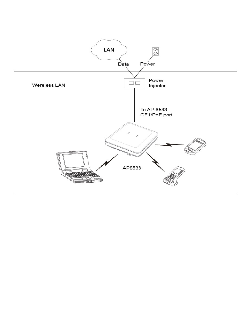
2.4 Power Injector System
An AP-8533 Access Point can receive power via an Ethernet cable connected
to the GE1/POE (LAN) port.
When users purchase a WLAN solution, they often need to place Access
Points in obscure locations. In the past, a dedicated power source was
Installation Guide 17
!
!
!
required for each Access Point in addition to the Ethernet infrastructure. This
often required an electrical contractor to install power drops at each Access
Point location. The Power Injector merges power and Ethernet into one cable,
reducing the burden of installation and allowing optimal Access Point
placement in respect to the intended coverage area.
Caution • Using a non-compliant injector, or an injector supporting legacy
modes prohibits the AP-8533 from functioning optimally.
Caution • Do not plug the AP-PSBIAS-2P3-ATR Power Injector into the
Access Point’s Console port. Connecting the Power Injector into the console
port can damage the port and void the AP-8533’s product warranty.
The AP-8533’s supported Power Injector (Part No. AP-PSBIAS-2P3-ATR) is a
high power POE Injector delivering up to 30 watts. The Access Point can only
use a Power Injector when connecting the unit to the Access Point’s GE1/POE
port. The Power Injector is separately ordered and not shipped with an
existing AP SKU.
The Access Point Power Supply (Part No. PWR-BGA48V45W0WW) is not
included with the Access Point and is orderable separately as an accessory. If
the Access Point is provided both POE power and PWR-BGA48V45W0WW
power concurrently, the Access Point will source power from the
PWR-BGA48V45W0WW supply only. Disconnecting the AC power from the
PWR-BGA48V45W0WW causes the Access Point to re-boot before sourcing
power from the POE Power Injector. If the AP is operating using injector
supplied power, the AP will not automatically reboot if an AC adapter is
connected. The Access Point continues to operate with power supplied from
the AC adapter without change to the Access Point operating configuration. If
using AC adapter supplied power and a change to the AP’s operating
configuration is warranted, the Access Point needs to be manually rebooted.
Caution • The Access Point supports any standards-based compliant power
source. However, using the wrong solution (including a POE system used on a
legacy Access Point) could either limit functionality or severely damage the
Access Point and void the product warranty.
18 AP-8533 Access Point
A separate Power Injector is required for each AP-8533 Access Point
comprising the network.
The Power Injector can be installed free standing, on an even horizontal
surface or wall mounted using the Power Injector's wall mounting key holes.
The following guidelines should be adhered to before cabling the Power
Injector to an Ethernet source and an Access Point:
• Do not block or cover airflow to the Power Injector.
• Keep the Power Injector away from excessive heat, humidity, vibration
and dust.

Installation Guide 19
!
!
• The Power Injector isn’t a repeater, and does not amplify the Ethernet
signal. For optimal performance, ensure the Power Injector is placed as
close as possible to the data port.
Caution • To avoid problematic performance and restarts, disable POE from a
wired switch port connected to an Access Point if mid-span power sourcing
equipment (PSE) is used between the two, regardless of the manufacturer of
the switch.
Caution • Ensure AC power is supplied to the Power Injector using an AC
cable with an appropriate ground connection approved for the country of
operation.
To install the Power Injector to an Ethernet data source and an Access Point:
1. Connect the Power Injector to an AC outlet (110VAC to 220VAC).
2. Connect an RJ-45 Ethernet cable between the Power Injector Data &
Power Out connector and the Access Point’s GE1/POE port.
3. Connect an RJ-45 Ethernet cable between the network data supply
(host) and the Power Injector Data In connector.
Ensure the cable length from the Ethernet source (host) to the Power
Injector and Access Point does not exceed 100 meters (333 ft).
The Power Injector has no On/Off power switch. The Injector receives
power and is ready for device connection and operation as soon as AC
power is applied. Refer to the Installation Guide shipped with the Power
Injector for a description of the device’s LEDs.
2.5 Wall Mount Instructions
A wall mount deployment requires hanging the AP-8533 Access Point with the
provided mounting bracket and two screws. The AP-8533 can be mounted on
to any plaster, wood or cement wall surface using the provided mounting
bracket.
The hardware required to install the AP-8533 on a wall consists of:
• Two wide-shoulder Phillips pan head self-tapping screws (M3.5 x 0.6 x
23 mm)
• Mounting bracket
Optional customer provided installation tools include:
• Phillips head screw driver, or drill and drill bit
 Loading...