

Extreme Networks AP-7522, AP-7532 Installation Manual

AP-7522 Access Point
Installation Guide
Published June 2017
9035076-01
9035076-01
Published June 2017
9035076-01

Copyright © 2017 Extreme Networks, Inc. All Rights Reserved.
Legal Notices
Extreme Networks, Inc. reserves the right to make changes in specifications and other
information contained in this document and its website without prior notice. The reader
should in all cases consult representatives of Extreme Networks to determine whether any
such changes have been made.
The hardware, firmware, software or any specifications described or referred to in this
document are subject to change without notice.
Trademarks
Extreme Networks and the Extreme Networks logo are trademarks or registered
trademarks of Extreme Networks, Inc. in the United States and/or other countries.
All other names (including any product names) mentioned in this document are the
property of their respective owners and may be trademarks or registered trademarks of
their respective companies/owners.
For additional information about Extreme Networks trademarks, go to:
www.extremenetworks.com/company/legal/trademarks/
Support
For product support, including documentation, visit: www.extremenetworks.com/support/

Contents
Introduction ...............................................................................................................3
AP-7522 Access Point Overview .................................................................................................................................3
Document Conventions ..................................................................................................................................................3
Warnings ...............................................................................................................................................................................3
Site Preparation ................................................................................................................................................................ 4
AP-7522 Package Contents ......................................................................................................................................... 4
Features ........................................................................................................................................................................................... 4
AP-7522 Antennas ...........................................................................................................................................................4
AP-7522 Dual Band 2.4 GHz / 5 GHz Antennas - US ....................................................................................................4
AP-7522 Dual Band 2.4 GHz / 5 GHz Antennas - EMEA .............................................................................................. 5
AP-7522 Internal Antenna Model .......................................................................................................................................... 6
AP-7522 Dual Band 2.4 GHz / 5 GHz Antennas - Canada .......................................................................................... 6
Hardware Installation ...............................................................................................7
Installation Instructions ...................................................................................................................................................7
Precautions ..........................................................................................................................................................................7
Access Point Placement ................................................................................................................................................ 8
Power Injector System ................................................................................................................................................... 8
Wall Mount Instructions ................................................................................................................................................10
Wall Mount Procedure - New Installation ........................................................................................................................ 10
Wall Mount Procedure - Existing Access Point Replacement ..................................................................................12
Suspended Ceiling T-Bar Mount Installation ........................................................................................................ 12
LED Indicators ...................................................................................................................................................................16
Basic Access Point Configuration......................................................................... 19
AP-7522 Access Point Specifications ..................................................................27
Electrical Characteristics ............................................................................................................................................. 27
Physical Characteristics ............................................................................................................................................... 27
Radio Characteristics .................................................................................................................................................... 28
................................................................................................................................................................................................28
Regulatory Information......................................................................................... 29
Regulatory Information ................................................................................................................................................29
Wireless Device Country Approvals ....................................................................................................................... 29
Country Selection ..................................................................................................................................................................... 30
Frequency of Operation – FCC and IC ............................................................................................................................. 30
Health and Safety Recommendations ...................................................................................................................30
Warnings for the use of Wireless Devices .......................................................................................................................32
Potentially Hazardous Atmospheres – Fixed Installations .......................................................................................32
Safety in Hospitals .....................................................................................................................................................................32
RF Exposure Guidelines ...............................................................................................................................................32
Safety Information .....................................................................................................................................................................32
Reducing RF Exposure - Use Properly ........................................................................................................................................... 32
International .................................................................................................................................................................................32
1

Contents
EU .....................................................................................................................................................................................................33
Remote and Standalone Antenna Configurations ..................................................................................................................... 33
US and Canada ...........................................................................................................................................................................33
Co-located statement ........................................................................................................................................................................... 33
Remote and Standalone Antenna Configurations .....................................................................................................................33
Power Supply ...................................................................................................................................................................34
Radio Frequency Interference Requirements—FCC ........................................................................................34
Radio Transmitters (Part 15) ..................................................................................................................................................34
Radio Frequency Interference Requirements - Canada ............................................................................................34
CE Marking and European Economic Area (EEA) ............................................................................................35
Statement of Compliance ...........................................................................................................................................36
Japan (VCCI) - Voluntary Control Council for Interference ..........................................................................36
Korea Warning Statement for Class B ITE ...........................................................................................................36
Other Countries ...............................................................................................................................................................36
Waste Electrical and Electronic Equipment (WEEE) ....................................................................................... 38
TURKISH WEEE Statement of Compliance ......................................................................................................... 39
End-User License Agreement................................................................................ 41
AP-7522 Access Point China ROHS Compliance............................................... 47
[Book Title]
2
Introduction
1
AP-7522 Access Point Overview
The AP-7522 external antenna and internal antenna Access Point’s are mid-tier Access
Point’s with a relatively small footprint which supports functionality for dependable and
efficient network performance.The AP-7522 is a 2x2:2 802.11ac Access Point utilizing one 2.4
GHz 802.11n radio and one 5 GHz 802.11ac radio. The Access Point housing is Plenum-rated
(UL2043).
The Access Point’s unique WiNG 5 software enables the Access Point to function as either a
Standalone Access Point, an Adaptive Access Point, or a Virtual Controller.
Updated versions of this guide could be periodically released to the Support site as new
product functionality is introduced. For more information, see http://extremenetworks.com/
support/documentation.
This document is written for the qualified network device installer.
Document Conventions
The following graphical alerts are used in this document to indicate notable situations:
NOTE
This is note text.
CAUTION
This is caution text.
WARNING
This is warning text.
Warnings
• Read all installation instructions and site survey reports, and verify correct equipment
installation before connecting the AP-7522 Access Point.
• Remove jewelry and watches before installing this equipment.
• Verify any device connected to this unit is properly wired and grounded.
AP-7522 Installation Guide
3

• Verify there is adequate ventilation around the device, and that ambient temperatures
meet equipment operation specifications.
Site Preparation
• Consult your site survey and network analysis reports to determine specific equipment
placement, power drops, and so on.
• Assign installation responsibility to the appropriate personnel.
• Identify and document where all installed components are located.
• Ensure adequate, dust-free ventilation to all installed equipment.
• Identify and prepare Ethernet and console port connections.
• Verify cable lengths are within the maximum allowable distances for optimal signal
transmission.
AP-7522 Package Contents
Introduction
An AP-7522 Access Point is available in external antenna (AP-7522) and internal antenna
(AP-7522I) configurations. An AP-7522 ships with the following:
• AP-7522 Access Point
• AP-7522 Installation Guide (This Guide)
• Wall mount screws and mounting bracket
Features
An AP-7522 Access Point supports the following feature set:
• Two RJ-45 connectors (GE1/POE and Console)
•Two LED indicators
• One 2.4 GHz 802.11n radio and one 5 GHz 802.11ac radio
• 2x2 MIMO, 2 spatial streams
• The GE1/POE accepts 802.3at or 802.3af compliant power from an external source.
NOTE
When operating in a Gigabit Ethernet environment, CAT-5e or CAT-6 cable is
recommended for Gigabit operation.
AP-7522 Antennas
AP-7522 Dual Band 2.4 GHz / 5 GHz Antennas - US
AP-7522 Installation Guide
4

Introduction
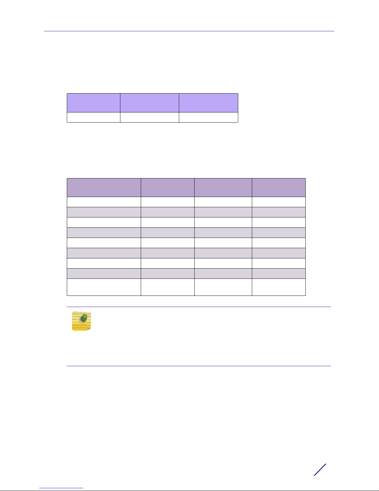
*An AP-7522 external antenna Access Point supports the following dual band antenna
options for the US:
NOTE
Per FCC requirement, the use of the Access Point on UNII-1 of 5GHz band
requires installers to input antenna elevation gain during configuration if the AP
placement is for outdoor coverage. This information can be found in Enterprise
Wireless LAN Antenna Specification Guide located at http://
extremenetworks.com/support/documentation
Elevation Gain
Antenna
Part Number
ML-2452-APA2-01 Dipole 3.17 4.85 na*
ML-2452-HPA5-036 Dipole 3 5 -2.56
ML-2452-APAG2A1-01 Dipole 2.7 1.7 na*
ML-2452-HPAG4A6-01 Dipole 4 7.3 5.7
ML-2452-HPA6-01 Dipole 5.3 6.1 4.09
ML-2452-PNL9M3-N36 Polarized-
ML-2452-PNA5-01R Panel 5.5 6 5.2
ML-2452-PTA3M3-036 Patch 5 4 na*
ML-2452-VMM5M3-
N72
Type
Panel
Patch 4.5 5.4 2.9
2.4 GHZ
Gain (dBi)
11 10.7 7. 3
5 GHZ Gain
(dBi)
for outdoor
placement (dBi
)
*This antenna is for indoor placement only.
AP-7522 Dual Band 2.4 GHz / 5 GHz Antennas - EMEA
*An external antenna AP-7522 supports the following dual band antenna options for the
EMEA:
Part Number Antenna Type
ML-2452-APA2-01 Dipole 3.17 4.85
ML-2452-HPA5-036 Dipole 3 5
ML-2452-APAG2A1-01 Dipole 2.7 1.7
ML-2452-HPAG4A6-01 Dipole 4 7.3
ML-2452-HPA6-01 Dipole 5.3 6.1
ML-2452-PNL6M3-N36 Polarized-Panel 6 6
ML-2452-PNA5-01R Panel 5.5 6
ML-2452-PTA3M3-036 Patch 5 4
ML-2452-VMM5M3-N72 Patch 4.5 5.4
AP-7522 Installation Guide
2.4 GHZ Gain
(dBi)
5 GHZ Gain
(dBi)
5
AP-7522 Internal Antenna Model
An AP-7522 internal antenna Access Point supports the following dual band antenna:
2.4 GHZ Gain
Antenna Type
PIFA 4.13 5.92
(dBi)
5 GHZ Gain
(dBi)
AP-7522 Dual Band 2.4 GHz / 5 GHz Antennas - Canada
*An external antenna AP-7522 supports the following dual band antenna options for
Canada:
Introduction
2.4 GHZ Gain
Part Number Antenna Type
ML-2452-APA2-01 Dipole 3.17 4.85
ML-2452-HPA5-036 Dipole 3 5
ML-2452-APAG2A1-01 Dipole 2.7 1.7
ML-2452-HPAG4A6-01 Dipole 4 7. 3
ML-2452-HPA6-01 Dipole 5.3 6.1
ML-2452-PNL9M3-N36 Polarized-Panel 11 10.7
ML-2452-PNA5-01R Panel 5.5 6
ML-2452-PTA3M3-036 Patch 5 4
ML-2452-VMM5M3 -
N72
Patch 4.5 5.4
(dBi)
5 GHZ Gain
(dBi)
NOTE
A professional installer must enter the antenna type, gain, and indoor/outdoor
placement using the CLI. The AP software uses this information and hardcode
maximum limits determined during testing to limit the EIRP. Please note, the
maximum EIRP in band 5.25-5.35GHz is limited to 23dBm. This limit is
hardcoded in the software for this band.
AP-7522 Installation Guide
6
Hardware Installation
2
Installation Instructions
An AP-7522 Access Point mounts either on a wall (with M 3.5 x 0.6 x 23 MM pan head
screws and mounting bracket- or equivalent) or on a suspended ceiling T-bar.
To prepare for the installation:
1 Match the part number on the purchase order with the part numbers in the packing list
and on the case of the Access Point.
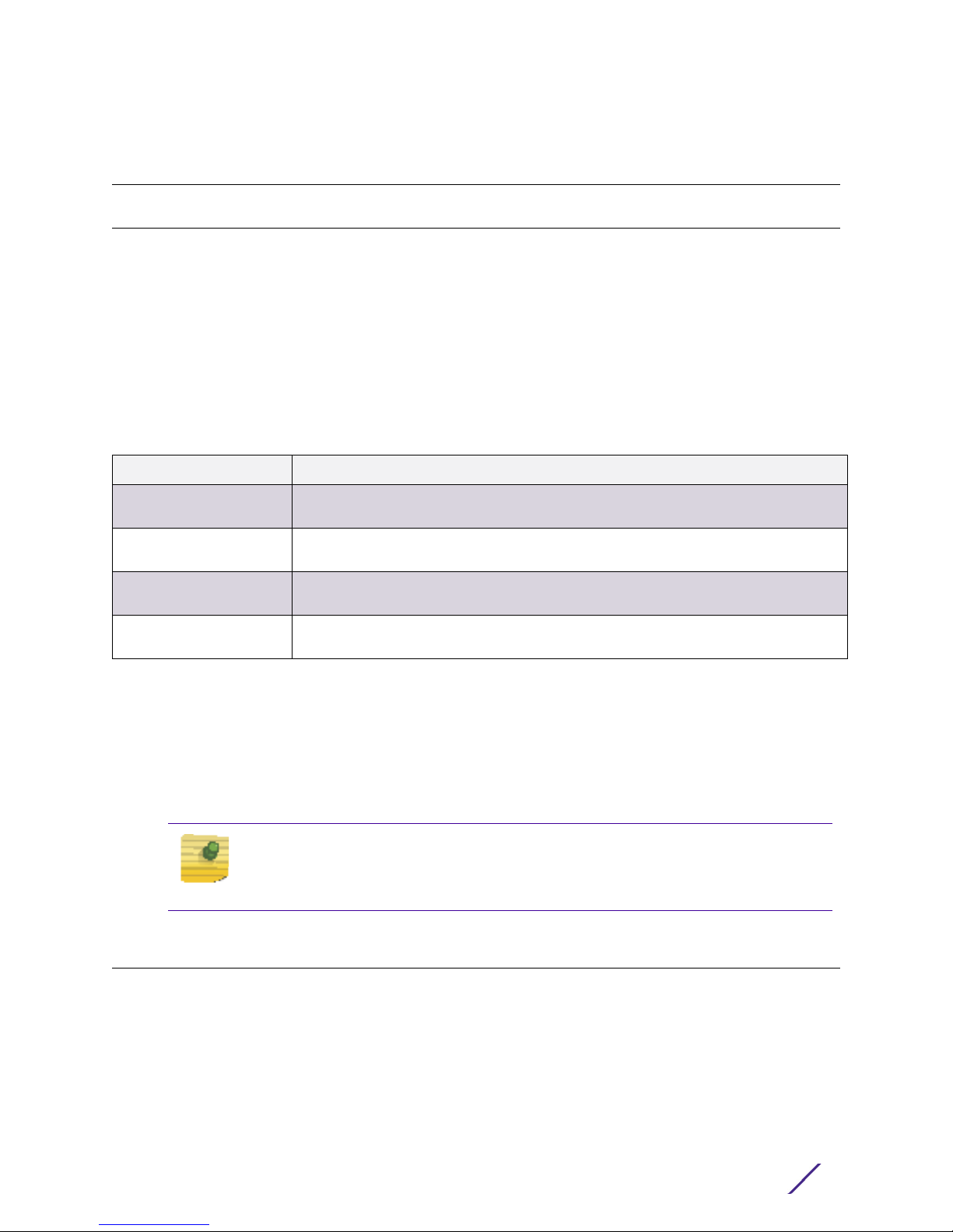
2 Verify the contents of the box include the intended AP-7522 Access Point, and the
included hardware matches the package contents (see AP-7522 Package Contents on
page 6).
Part Number Description
AP-7522-67040-US AP-7522 dual radio 802.11ac 2x2:2 MIMO Access Point external antenna
US version
AP-7522-67040-1-WR AP-7522 dual radio 802.11ac 2x2:2 MIMO Access Point external antenna
International version
AP-7522-67030-US AP-7522 dual radio 802.11ac 2x2:2 MIMO Access Point internal antenna
US version
AP-7522-67030-1-WR AP-7522 dual radio 802.11ac 2x2:2 MIMO Access Point internal antenna
International version
3 Review site survey and network analysis reports to determine the location and mounting
position for the AP-7522 Access Point.
4 Connect a CAT-5 or better Ethernet cable to a compatible 802.3at or 802.3af power
source and run the cable to the installation site. Ensure there is sufficient slack on the
cable to perform the installation steps.
NOTE
When operating in a Gigabit Ethernet environment, CAT-5e or CAT-6 cable is
recommended for Gigabit operation.
Precautions
Before installing an AP-7522 Access Point, verify the following:
• Your are using the correctly rated power solution for the AP-7522 (either the APPSBIAS-2P3-ATR power injector or the PWRS-14000-54R external power supply)
• Do not install the AP-7522 in wet or dusty areas.
• Verify the environment has a continuous temperature range between -4° F to 104° F/20° C to 40° C for external antenna Access Points and 32° F to 104° F/0° C to 40° C for
internal antenna Access Points.
AP-7522 Installation Guide
7

Access Point Placement
For optimal performance, install the Access Point away from transformers, heavy-duty
motors, fluorescent lights, microwave ovens, refrigerators and other industrial equipment.
Signal loss can occur when metal, concrete, walls or floors block transmission. Install the
Access Point in an open area or add Access Points as needed to improve coverage.
Antenna coverage is analogous to lighting. Users might find an area lit from far away to be
not bright enough. An area lit sharply might minimize coverage and create dark areas.
Uniform antenna placement in an area (like even placement of a light bulb) provides even,
efficient coverage.
Install the Access Point at an ideal height of 10 feet from the ground.
To maximize the Access Point’s radio coverage area, conduct a site survey to define and
document radio interference obstacles before installing the Access Point.
Power Injector System
Hardware Installation
An AP-7522 Access Point can receive power via an Ethernet cable connected to the GE1/
POE (LAN) port.
When users purchase a WLAN solution, they often need to place Access Points in obscure
locations. In the past, a dedicated power source was required for each Access Point in
addition to the Ethernet infrastructure. This often required an electrical contractor to install
power drops at each Access Point location. The Power Injector merges power and Ethernet
into one cable, reducing the burden of installation and allowing optimal Access Point
placement in respect to the intended coverage area.
CAUTION
Using a non-compliant injector, or an injector supporting legacy modes will not
allow the AP-7522 to function at optimum performance levels.
CAUTION
Do not plug the AP-PSBIAS-2P3-ATR Power Injector into the Access Point’s
Console port. Connecting the Power Injector into the console port can damage
the port and void the AP-7522’s product warranty.
The AP-7522’s supported Power Injector (Part No. AP-PSBIAS-2P3-ATR) is a high power
POE Injector delivering up to 30 watts. The Access Point can only use a Power Injector
when connecting the unit to the Access Point’s GE1/POE port. The Power Injector is
separately ordered and not shipped with an existing AP SKU.
The Access Point Power Supply (Part No. PWRS-14000-54R) is not included with the
Access Point and is orderable separately as an accessory. If the Access Point is provided
both POE power and PWRS-14000-54R power concurrently, the Access Point will source
AP-7522 Installation Guide
8
Hardware Installation
power from the PWRS-14000-54R supply only. Disconnecting the AC power from the
PWRS-14000-54R causes the Access Point to re-boot before sourcing power from the POE
power injector. If the AP is operating using injector supplied power, the AP will not
automatically reboot if an AC adapter is connected. The Access Point continues to operate
with power supplied from the AC adapter without change to the Access Point operating
configuration. If using AC adapter supplied power and a change to the AP’s operating
configuration is warranted, the Access Point needs to be manually rebooted by the
customer.
CAUTION
The Access Point supports any standards-based compliant power source.
However, using the wrong solution (including a POE system used on an Access
Point) could either limit functionality or severely damage the Access Point and
void the product warranty.
A separate Power Injector is required for each AP-7522 Access Point comprising the
network.
The Power Injector can be installed free standing, on an even horizontal surface or wall
mounted using the power injector’s wall mounting key holes. The following guidelines
should be adhered to before cabling the Power Injector to an Ethernet source and an
Access Point:
• Do not block or cover airflow to the Power Injector.
AP-7522 Installation Guide
9
Hardware Installation
• Keep the Power Injector away from excessive heat, humidity, vibration and dust.
The Power Injector isn’t a repeater, and does not amplify the Ethernet signal. For optimal
performance, ensure the Power Injector is placed as close as possible to the data port.
CAUTION
To avoid problematic performance and restarts, disable POE from a wired
switch port connected to an Access Point if mid-span power sourcing
equipment (PSE) is used between the two, regardless of the manufacturer of
the switch.
CAUTION
Ensure AC power is supplied to the Power Injector using an AC cable with an
appropriate ground connection approved for the country of operation.
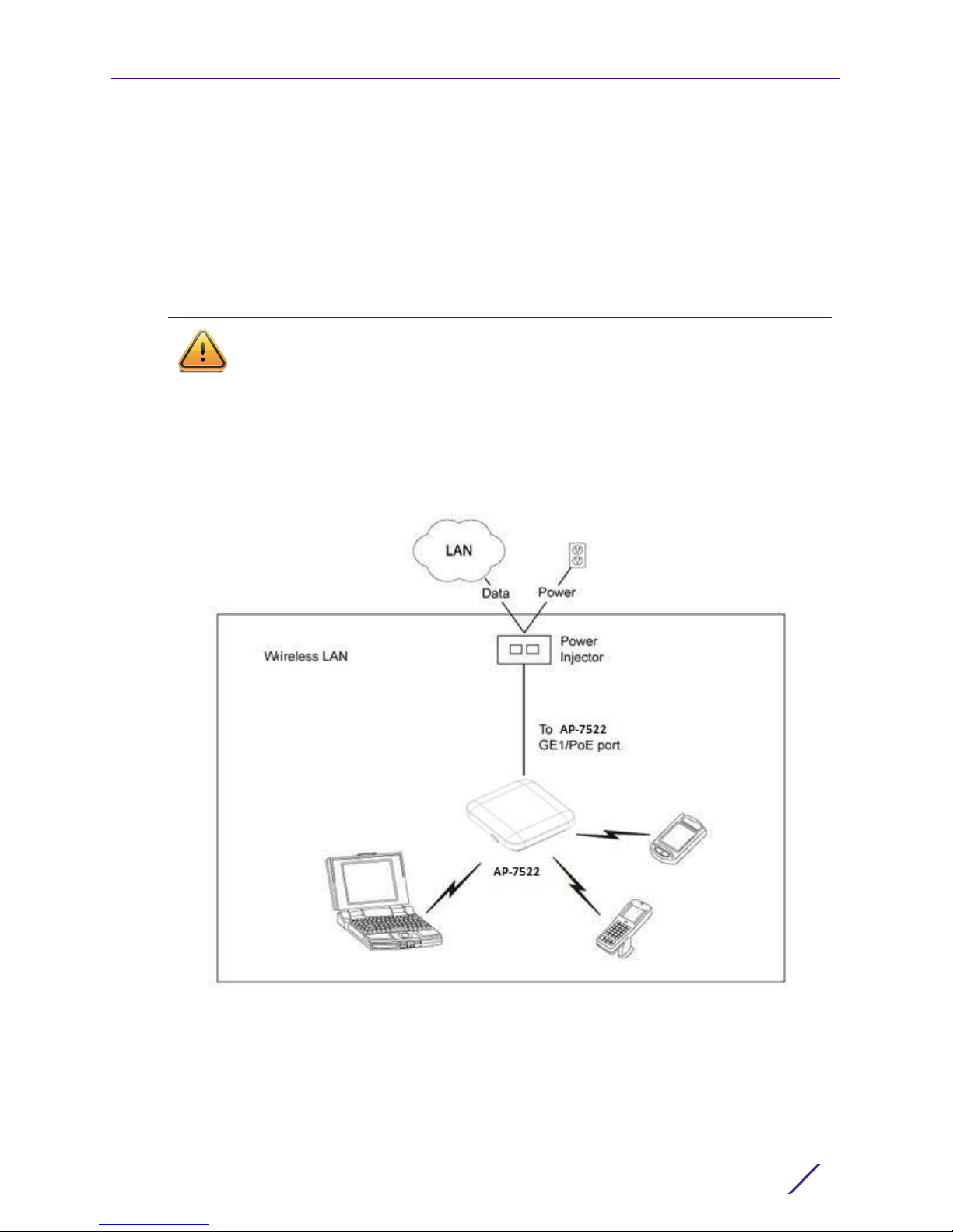
To install the Power Injector to an Ethernet data source and an Access Point:
1 Connect the Power Injector to an AC outlet (110VAC to 220VAC).
2 Connect an RJ-45 Ethernet cable between the Power Injector Data & Power Out
connector and the Access Point’s GE1/POE port.
3 Connect an RJ-45 Ethernet cable between the network data supply (host) and the
Power Injector Data In connector.
Ensure the cable length from the Ethernet source (host) to the Power Injector and Access
Point does not exceed 100 meters (333 ft).
The Power Injector has no On/Off power switch. The Injector receives power and is ready
for device connection and operation as soon as AC power is applied. Refer to the
Installation Guide shipped with the Power Injector for a description of the LEDs.
Wall Mount Instructions
A wall mount deployment requires hanging the AP-7522 Access Point with the provided
mounting bracket and two screws. The AP-7522 can be mounted on to any plaster, wood or
cement wall surface using the provided mounting bracket.
The hardware required to install the AP-7522 on a wall consists of:
• Two wide-shoulder Phillips pan head self-tapping screws (M3.5 x 0.6 x 23 mm)
• Mounting bracket
Optional customer provided installation tools include:
• Phillips head screw driver, or drill and drill bit
Wall Mount Procedure - New Installation
AP-7522 Installation Guide
10
Hardware Installation
This section describes a new AP-7522 installation with no previous Access Point existing on
the intended wall surface.
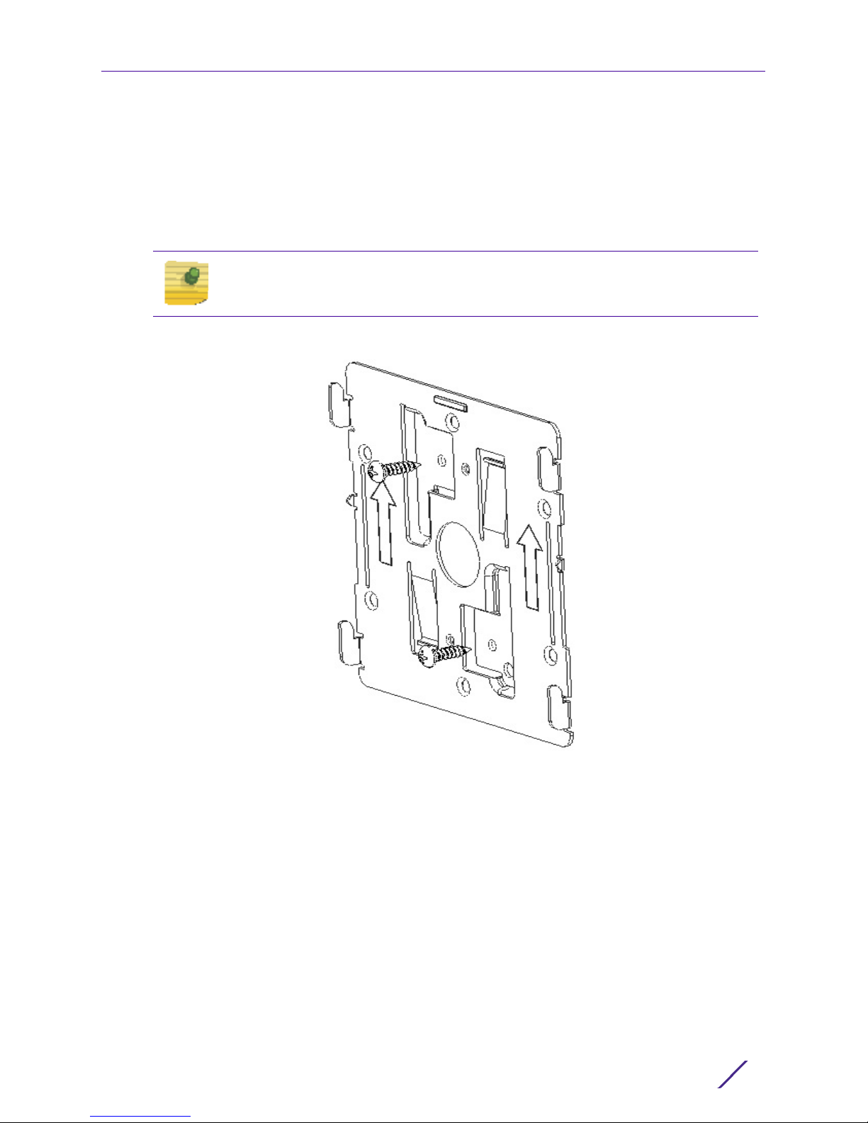
1 Place the mounting bracket against the wall.
2 Mark the screw hole locations depending on the intended deployment orientation of the
unit.
NOTE
When pre-drilling a hole the recommended hole size is 4mm (0.16in.).
3 At each point, drill a hole in the wall and attach the mounting bracket.
4 Place the Access Point on the mounting bracket.
5 Cable the Access Point using either the Power Injector solution (AP-PSBIAS-2P3-ATR) or
the approved AP-7522 power supply (PWRS-14000-54R).
For Power Injector installations:
a Connect a RJ-45 CAT5e (or CAT6) Ethernet cable between the Power Injector Data &
Power Out connector and the Access Point’s GE1/POE port.
b Connect a RJ-45 CAT5e (or CAT6) Ethernet cable between the network data supply
(host) and the Power Injector Data In connector.
c Ensure the cable length from the Ethernet source (host) to the Power Injector and
Access Point does not exceed 100 meters (333 ft). The Power Injector has no On/Off
power switch. The Power Injector receives power as soon as AC power is applied.
For standard power adapter (non Power Injector) and line cord installations:
AP-7522 Installation Guide
11

Hardware Installation
a Connect a RJ-45 Ethernet cable between the network data supply (host) and the
Access Point’s GE1/POE port.
b Verify the power adapter is correctly rated according to the country of operation.
c Connect the power supply line cord to the power adapter.
d Attach the power adapter cable into the power connector on the Access Point.
e Attach the power supply line cord to a power supply.
6 Verify the Access Point is receiving power by observing the LEDs are lit or flashing. For
more information on AP-7522 LED behavior, see
Indicators on page 16.
7 The Access Point is ready to configure.
<bl_blue><em_Emphasis>LED
CAUTION
If not using an AP-PSBIAS-2P3-ATR power injector, ensure only the AP-7522’s
designated power supply (PWRS-14000-54R) is used to supply power to the
Access Point. Using an incorrectly rated power supply could damage the
Access Point and void the product warranty. Do not actually connect to the
power source until the cabling portion of the installation is complete.
Wall Mount Procedure - Existing Access Point Replacement
An existing AP-7131 or AP-7131N Series Access Point installed on a wall can be replaced by
an AP-7522. Simply remove the existing AP-7131 or AP-7131N and install the new provided
mounting bracket for AP-7522 directly to the wall. The cabling procedure for such a
replacement is as described in the previous section.
Suspended Ceiling T-Bar Mount Installation
Ceiling mount requires holding the AP-7522 up against a T-bar of a suspended ceiling grid
and twisting the unit on to the T-bar. If deploying the AP-7522 on a sculpted ceiling T-Bar,
the Access Point mounting kit (Part No. KT-135628-01) can optionally be used as well.
AP-7522 Installation Guide
12
Hardware Installation
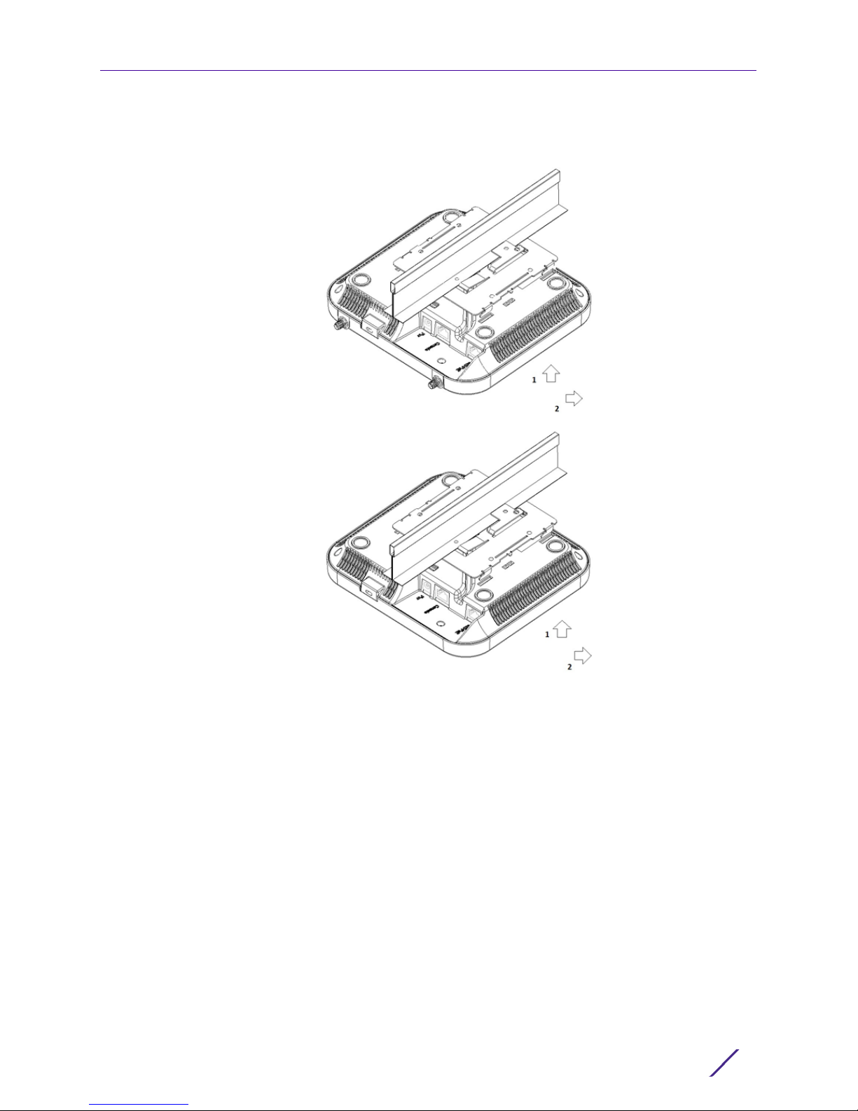
1 First install the mounting bracket on the T-bar then attach the mounting plate using the
mounting slots on the Access Point.
2 Cable the Access Point using either the Power Injector solution (AP-PSBIAS-2P3-ATR) or
the approved AP-7522 power supply (PWRS-14000-54R).
For Power Injector installations:
a Connect a RJ-45 CAT5e (or CAT6) Ethernet cable between the network data supply
(host) and the Power Injector Data In connector.
b Connect a RJ-45 CAT5e (or CAT6) Ethernet cable between the Power Injector Data &
Power Out connector and the Access Point’s GE1/POE port.
c Ensure the cable length from the Ethernet source (host) to the Power Injector and
Access Point does not exceed 100 meters (333 ft). The Power Injector has no On/Off
power switch, and receives power as soon as AC power is applied.
For standard power adapter (non Power Injector) and line cord installations:
a Connect a RJ-45 Ethernet cable between the network data supply (host) and the
Access Point’s GE1/POE port.
b Verify the power adapter is correctly rated according the country of operation.
c Connect the power supply line cord to the power adapter.
d Attach the power adapter cable into the power connector on the Access Point.
AP-7522 Installation Guide
13
 Loading...