

Extreme Networks Altitude 4760 Series Installation Manual

Altitude™ 4760 Series Access Point
Installation Guide
Extreme Networks, Inc.
3585 Monroe Street
Santa Clara, California 95051
(888) 257-3000
(408) 579-2800
http://www.extremenetworks.com
Published: September 2012
Part number: 120799-00 Rev 01

AccessAdapt, Alpine, Altitude, BlackDiamond, EPICenter, ExtremeWorks Essentials, Ethernet
Everywhere, Extreme Enabled, Extreme Ethernet Everywhere, Extreme Networks, Extreme Standby
Router Protocol, Extreme Turbodrive, Extreme Velocity, ExtremeWare, ExtremeWorks, ExtremeXOS, Go
Purple Extreme Solution, ExtremeXOS ScreenPlay, ReachNXT, Sentriant, ServiceWatch, Summit,
SummitStack, Triumph, Unified Access Architecture, Unified Access RF Manager, UniStack, the
Extreme Networks logo, the Alpine logo, the BlackDiamond logo, the Extreme Turbodrive logo, the
Summit logos, and the Powered by ExtremeXOS logo are trademarks or registered trademarks of
Extreme Networks, Inc. or its subsidiaries in the United States and/or other countries.
sFlow is a registered trademark of InMon Corporation.
Specifications are subject to change without notice.
All other registered trademarks, trademarks, and service marks are property of their respective
owners.
© 2012 Extreme Networks, Inc. All Rights Reserved.
2
Altitude™ 4760 Access Point Installation Guide

Table of Contents
Chapter 1: Introduction....................................................................................................5
Document Conventions...............................................................................................................7
Altitude 4760 Series Access Point Hardware ............................................................................. 8
Altitude 4760 Series Access Point Antennas..............................................................................9
Outdoor PoE Hardware and Mounting Accessories ................................................................. 10
Altitude 4760 Series Mounting Accessories ...................................................................... 10
Package Contents ....................................................................................................................11
Hardware Installation Guidelines .............................................................................................. 12
Precautions............................................................................................................................... 12
Warnings................................................................................................................................... 13
Chapter 2: Hardware Installation ..................................................................................15
Access Point Placement ........................................................................................................... 15
Altitude 4760 Hardware Overview ............................................................................................ 16
Altitude 4760 Series Access Point Ports and Connections....................................................... 16
Altitude 4760 Access Point Antenna Connectors .............................................................. 17
Altitude 4760 Series Access Point Console, GE1/POE and GE2 Ports ............................19
Altitude 4760 Series Access Point Grounding Screw........................................................ 21
Altitude 4760 Series Access Point Factory Reset Hardware Button ................................. 22
LED Indicators ..........................................................................................................................23
Two Radio LEDs................................................................................................................ 24
Three Radio LEDs............................................................................................................. 25
Altitude 4760 Series Access Point Hardware Mounting and Installation .................................. 26
Mounting Bracket Kit ......................................................................................................... 26
Extension Arm Kit .............................................................................................................. 28
Pole Mounted Installations ................................................................................................ 29
Vertical Pole Mount ........................................................................................................... 30
Wall Mounted Installations................................................................................................. 34
Altitude 4760 Series Access Point Power Options Using Power over Ethernet ....................... 37
Chapter 3: Initial Access Point Configuration .............................................................39
Antenna Type Configuration ..................................................................................................... 39
Automatic Channel Select Override.......................................................................................... 40
The Initial Setup Wizard............................................................................................................ 41
Altitude™ 4760 Series Access Point Installation Guide
3

Table of Contents
Chapter 4: Specifications ..............................................................................................63
Hardware Specifications ...........................................................................................................63
Environmental Specifications....................................................................................................64
Radio Specifications ................................................................................................................. 64
Networking and Software Specifications................................................................................... 65
Approvals.................................................................................................................................. 65
Optional Accessories ................................................................................................................ 66
Basic Troubleshooting .............................................................................................................. 66
Chapter 5: Regulatory Information ...............................................................................67
FCC Approval Statement ..........................................................................................................67
TDWR Location Information .............................................................................................. 71
Wireless Country Approvals......................................................................................................72
Health and Safety Recommendations ...................................................................................... 73
Warnings for the Use of Wireless Devices ........................................................................ 73
Potentially Hazardous Atmospheres.................................................................................. 73
Safety in Hospitals.............................................................................................................73
RF Exposure Guidelines...........................................................................................................73
Safety Information ............................................................................................................. 73
Reduce RF Exposure - Use Properly ................................................................................ 74
Remote and Standalone Antenna Configurations ............................................................. 74
Power Supply............................................................................................................................74
Wireless Devices - Countries....................................................................................................74
Country Selection .............................................................................................................. 74
Operation in the US ........................................................................................................... 74
Radio Frequency Interference Requirements - FCC ................................................................ 75
Radio Transmitters (Part 15) ............................................................................................. 75
Radio Frequency Interference Requirements - Canada.................................................... 75
Radio Transmitters ............................................................................................................ 76
CE Marking and European Economic Area (EEA).................................................................... 76
Statement of Compliance.......................................................................................................... 77
Other Countries .................................................................................................................77
Waste Electrical and Electronic Equipment (WEEE) ................................................................ 80
Chapter 6: Customer Support .......................................................................................82
Registration............................................................................................................................... 82
Documentation.......................................................................................................................... 83
4
Altitude™ 4760 Series Access Point Installation Guide

Introduction
1
CHAPTER
Perfect for extending network coverage to outside areas, the Altitude™ 4760 Series Access
Point brings the latest 802.11n 3x3 Multiple Input Multiple Output (MIMO) tri-radio design
together with rugged outdoor performance. True perimeter security is provided using either
a dedicated dual-band sensor or software mode for both 2.4 GHz and 5 GHz bands to
deliver 24x7 rogue detection and termination. The Altitude 4760 Series Access Point is
optimized with the Extreme Networks
security, and mobility services to the Access Point to support better capacity and
performance. The Altitude 4760 Series Access Point is ideal for industrial, enterprise
campus, video surveillance, public safety, and smartgrid utility deployments to extend to
the outdoors.
®
Wireless Mobility 5 intelligence, extending QoS,
Deployments can be managed using the Extreme Networks Wireless Mobility 5 architecture.
The Extreme Networks Wireless Mobility 5 architecture is a solution designed for 802.11n
networking. It leverages the best aspects of independent and dependent architectures to
create a smart network that meets the connectivity, quality, and security needs of each user
and their applications based on the availability of network resources including wired
networks. The Wireless Mobility 5 software is a Third Generation WLAN solution which
incorporates the best of both the first generation Autonomous Access Point WLAN and the
second generation Centralized Controller Based WLAN.
The control plane is now distributed between the Access Points and the controllers. The
network administrator has the flexibility of directing the data plane either being forwarded
directly from the Access Points, or through the controllers. By distributing intelligence and
control between the wireless controllers and APs, the Wireless Mobility 5 network can route
directly through the best path, as determined by factors including the user, location,
application, and available wireless and wired resources.
Once adopted by Summit
is managed as an Adaptive AP running the Wireless Mobility network management
®
WM3000 Series Controller, the Altitude 4760 Series Access Point
Altitude™ 4760 Series Access Point Installation Guide
5

protocol. Extreme Networks Wireless Mobility 5 networks extend the differentiation that
Adaptive APs offered to the next level by now having the services and security available at
every point in the network. The traffic flow is optimized to prevent wired congestion as
well as wireless congestion. Traffic flows dynamically, based on user and application, and
finds alternate routes to work around any possible network choke points. Mixed-media
application optimization is the hallmark of Extreme Networks Wireless Mobility 5 networks.
Extending the indoor network to the outdoors increases the need to guard against
unwanted intruders and attackers, and monitor network performance and availability. In
addition to industry standard security for clients and radio backhaul, the Altitude 4760
Series Access Point provides true perimeter security using either a dedicated dual band
sensor or software mode in the 2.4 GHz and 5 GHz bands. Concurrent around-the-clock
dual band Network Assurance sensing and wireless traffic is provided together with
spectrum analysis, eliminating the need for separate devices.
An Access Point can function as a Wireless Intrusion Protection System (WIPS) sensor and
upload sensor mode operation information to a dedicated WIPS server. WIPS protects your
wireless network, mobile devices, and traffic from attacks and unauthorized access. WIPS
provides tools for standards compliance and around-the-clock 802.11a/b/g/n wireless
network security in a distributed environment. WIPS allows administrators to identify and
accurately locate attacks, rogue devices, and network vulnerabilities in real time and
permits both a wired and wireless lockdown of wireless device connections upon
acknowledgement of a threat.
Capacity in video surveillance solutions is critical to the performance of many networks
designed to monitor and provide safety. To assist with the deployment of video surveillance
networks where the camera application resides, the Altitude 4760 Series Access Point offers
band unlocked radio flexibility. The user can choose between 2.4 GHz, 5 GHz, and 4.9 GHz
bands for the radio type. The AP4760 supports 3x3 MIMO technology, reaching a maximum
data rate of 300 Mbps to maintain high performance and better quality of transmission.
The Altitude 4760 Series Access Point is designed to optimize network availability through
preemptive intelligence which dynamically senses weak or failing signals, securely moves
mobile users to alternate APs, and boosts signal power to automatically fill RF holes and
ensure uninterrupted mobile user access.
The Altitude 4760 Series Access Point band unlocked radios allow flexibility and
deployment options for the public safety market. The powerful radio increases coverage,
performance, and obstruction penetration for outdoor use. Receiver sensitivity is increased
proportionally so users have an increased ability to maintain high performance access for
mobility and client devices in the network.
Altitude™ 4760 Series Access Point Installation Guide
6

Document Conventions
Document Conventions
The following graphical alerts are used in this document to indicate notable situations:
NOTE
Tips, hints, or special requirements that you should take note of.
CAUTION
Care is required. Disregarding a caution can result in data loss or equipment malfunction.
WARNING!
Indicates a condition or procedure that could result in personal injury or equipment damage.
Altitude™ 4760 Series Access Point Installation Guide
7

Altitude 4760 Series Access Point Hardware
Altitude 4760 Series Access Point Hardware
There are currently six models of the Altitude 4760 Series Access Point.
SKU Part Number Description
AP4762-US 15794 Altitude 4762 dual-radio Independent Outdoor Access Point for US
regulatory domain, 802.11a/b/g/n, 3x3 MIMO. External antennas.
Powered by 802.3at PoE.
AP4762-EU 15811 Altitude 4762 dual-radio Independent Outdoor Access Point for
European Union regulatory domain, 802.11a/b/g/n, 3x3 MIMO.
External antennas. Powered by 802.3at PoE.
AP4762-ROW 15795 Altitude 4762 dual-radio Independent Outdoor Access Point for Rest
of the World regulatory domain, 802.11a/b/g/n, 3x3 MIMO. External
antennas. Powered by 802.3at PoE.
AP4763-US 15796 Altitude 4763 dual-radio with sensor Independent Outdoor Access
Point for US regulatory domain, 802.11a/b/g/n, 3x3 MIMO. External
antennas. Powered by 802.3at PoE.
AP4763-EU 15812 Altitude 4763 dual-radio with sensor Independent Outdoor Access
Point for European Union regulatory domain, 802.11a/b/g/n, 3x3
MIMO. External antennas. Powered by 802.3at PoE.
AP4763-ROW 15910 Altitude 4763 dual-radio with sensor Independent Outdoor Access
Point for Rest of the World regulatory domain, 802.11a/b/g/n, 3x3
MIMO. External antennas. Powered by 802.3at PoE.
Altitude™ 4760 Series Access Point Installation Guide
8

Altitude 4760 Series Access Point Antennas
Altitude 4760 Series Access Point Antennas
The Altitude 4760 Series Access Point antenna suite includes the following options:
Altitude 4760 Series Access Point 2.4 GHz Antennas
Height
Antenna Description Band Gain
Outdoor, dipole, 8dBi, N-Male, 2.4GHz 2.4 8 19.5 ML-2499-HPA8-01
Outdoor, dipole, 4dBi, N-Male, 2.4GHz 2.4 4 9.0 ML-2499-HPA4-01
Downtilt, 8dBI, N-Male, 2.4 GHz 2.4 8 21 RAN4054A
Altitude 4760 Series Access Point 5 GHz Antennas
Antenna Description Band Gain
(inches) P/N
Height
(inches) P/N
Outdoor, dipole, 10dBi, N-Male, 5Ghz 4.9-5.8 10 19.5 ML-5299-HPA10-01
Outdoor, dipole, 5dBi, N-Male, 5GHz 5.2-5.8 5 6.75 ML-5299-HPA5-01
Altitude 4760 Series Access Point Dual Band Antenna
Height
Antenna Description Band Gain
Outdoor, dipole, 4.5dBi/7.5dBi,
N-Male, multi-band
NOTE
The multi-band antenna is suggested for use with model numbers 15796, 15812, and 15910
on ports R3-A and R3-B, respectively.
2.4-5.0 4.5/7.5 11 ML-2452-HPAG5A8-01
(inches) P/N
For a more exhaustive overview of the antennas supported by the Extreme Networks
Access Point family, refer to the Enterprise Wireless LAN Antenna Specification Guide and
Enterprise Wireless LAN Antenna Specification Guide Addendum documents available from
http://www.extremenetworks.com/go/documentation
.
Altitude™ 4760 Series Access Point Installation Guide
9

Outdoor PoE Hardware and Mounting Accessories
Outdoor PoE Hardware and Mounting
Accessories
The Altitude 4760 Series Access Point is a Power over Ethernet (PoE) device. When deployed,
the use of an outdoor rated PoE power supply and mounting bracket may be required. The
recommended Extreme Networks PoE accessories are listed in the following table. For more
information, see “Altitude 4760 Series Access Point Power Options Using Power over
Ethernet” on page 37
Part Number Hardware Accessory
AP-PSBIAS-7161-US IP66 802.3at gigabit Ethernet power injector 100-240VAC US regulatory
AP-PSBIAS-7161-EU IP66 802.3at gigabit Ethernet power injector 100-240VAC European Union
AP-PSBIAS-7161-WW IP66 802.3at gigabit Ethernet power injector 100-240VAC Rest of World
.
domain
regulatory domain
regulatory domain.
KT-153143-01 Altitude 4760 Series Access Point outdoor PoE mount kit
Altitude 4760 Series Mounting Accessories
The Altitude 4760 Series Access Point has a flexible three piece mounting kit, together with
an optional standoff extension arm for pole mounting. For more information, see “Altitude
4760 Series Access Point Hardware Mounting and Installation” on page 26.
Part Number Hardware Accessory
KT-147407-01 Altitude 4760 Series Access Point mounting hardware kit - 3 pieces
KT-150173-01 Altitude 4760 Series Access Point 12 inch extension arm for mounting kit
KT-153676-01 Altitude 4760 Series Access Point RJ45 weatherized connector plug
Altitude™ 4760 Series Access Point Installation Guide
10

Package Contents
Package Contents
Carefully remove all protective packing material from around the Altitude 4760 Series
Access Point and save the container for later storage and shipping. Refer to “Altitude 4760
Series Access Point Hardware” on page 8 when verifying that all Altitude 4760 Series
Access Point hardware has been received. Record the serial numbers on the shipping
cartons and Altitude 4760 Series Access Points for warranty claims and reference during
software download procedures. When opening the shipping cartons, inspect the equipment
for damage. If you find any damaged equipment or any equipment is missing, contact
Extreme Networks Support immediately.
Each Altitude 4760 Series Access Point model number (see “Altitude 4760 Series Access
Point Hardware” on page 8) includes the following parts:
●
Altitude 4760 Series Access Point
●
Weatherproof RJ45 plug kit
●
Altitude™ 4760 Series Access Point Installation Guide (this document)
The following items are not included with the Altitude 4760 Series Access Point models, but
can be ordered from Extreme Networks:
●
Antennas
●
Mounting brackets/kits
●
PoE power supply and accessories
●
Summit WM3000 Series controllers (if required)
The following items are not provided by Extreme Networks and can be sourced from local
hardware suppliers:
●
Lightning protection unit
●
Cat5E cable to connect power source
●
Band clamps, lag bolts, or U-bolts
●
Grounding wire
Altitude™ 4760 Series Access Point Installation Guide
11

Hardware Installation Guidelines
Hardware Installation Guidelines
CAUTION
All device wiring must comply with the National Electric Code (NEC) or regulations and
procedures defined by the regulatory bodies of the country or region where the devices are being
deployed. All local building and structure codes must be observed.
WARNING!
Strictly observe the following safety warnings and precautions when installing an Altitude
4760 Series Access Point.
Precautions
Before installing an Altitude 4760 Series Access Point verify the following grounding and
lightning protection notes:
●
The installation professional should be familiar with all grounding requirements and
regional codes and ensure that the Access Point and mounting asset are properly
grounded. The grounding cable for an Altitude 4760 Series Access Point must be at a
minimum a #10 gauge wire cross section. The cable can be attached to the unit using one
of the following methods:
●
Loosen the grounding screw, insert the grounding cable into the hole below it, and
tighten the screw.
●
Loosen the grounding screw, wind the grounding cable around it, and tighten the
screw.
●
Attach a ring lug to the grounding cable and secure it to the unit using the grounding
screw.
●
To properly attach the grounding cable to the Access Point, refer to “Altitude 4760 Series
Access Point Grounding Screw” on page 21.
●
For Ethernet and lightning protection, it is recommended that a commercially available
off-the-shelf Lightning Protection Unit (LPU) be used on all shielded CAT5E Ethernet
connections. The LPU should be rated for outdoor use.
Altitude™ 4760 Series Access Point Installation Guide
12

Warnings
●
For the best possible protection, each Access Point requires an LPU be installed
adjacent to the Access Point. If there is a LAN connection to an indoor network, a
second LPU is required at the cable entry point to the buliding.
CAUTION
Lightning damage is not covered under the conditions of a standard Extreme Networks
product warranty. When installed correctly, Lightning Protection Units (LPUs) provide the best
protection from the harmful effects of lightning. Observe all regional and national codes that apply for
lightning protection.
●
Verify that the deployment environment has a continuous temperature range compatible
with the operating temperature range of the device.
Warnings
●
Read all installation instructions and site survey reports, and verify correct equipment
installation before connecting the Access Point to its power source.
●
Remove jewelry and watches before installing this equipment.
●
Verify that the unit is grounded before connecting it to the power source.
●
Verify that any device connected to this unit is properly wired and grounded.
●
Connect all power cords to a properly wired and grounded electrical circuit. Verify that
the electrical circuits have appropriate overload protection.
●
Attach only approved power cords to the device.
●
Verify that the power connector and socket are accessible at all times during the
operation of the equipment.
●
Do not hold any component containing a radio such that it is very close to or touching
any exposed parts of the body, especially the face or eyes, while transmitting.
●
Do not work with power circuits in dimly lit spaces.
●
Do not install this equipment or work with its power circuits during thunderstorms or
other weather conditions that could cause a power surge.
●
Verify there is adequate ventilation around the device, and that ambient temperatures
meet equipment operation specifications.
●
Avoid contact with overhead power lines.
Altitude™ 4760 Series Access Point Installation Guide
13

Warnings
●
Take precautions to avoid injury from falling tools and equipment. Crews should wear
hard hats in and around the installation work site.
●
Be aware of vehicular traffic in and around the installation work site.
●
Do not operate a portable transmitter near unshielded blasting caps or in an
environment where explosives are present unless the transmitter is especially certified
for such use.
●
Refer to your site survey, network analysis reports to determine specific requirements for
each deployment.
●
Assign installation responsibility to the appropriate personnel.
●
Identify and document where all installed components are located.
●
Identify and prepare Ethernet and console port connections.
●
Verify that cable lengths are within the maximum allowable distances for optimal signal
transmission.
CAUTION
The maximum length allowed for PoE cables is 100 meters.
Altitude™ 4760 Series Access Point Installation Guide
14

Hardware Installation
2
CHAPTER
Altitude 4760 Series Access Point models can be purchased in a two or three radio
configuration (see “Altitude 4760 Series Access Point Hardware” on page 8). Each model
has two band unlocked radios that can operate across the 2.4 GHz, 4.9 GHz, and 5 GHz
bands, subject to country regulatory approval and outdoor/band use.
An Altitude 4760 Series Access Point must be installed by trained professionals familiar
with RF planning and regulatory limits defined by the regulatory bodies of the country
where the devices are being deployed. All common precautions for grounding and
Electrostatic Discharge (ESD) protection should be observed during deployment and
installation. Altitude 4760 Series Access Points must be installed such that no harmful
interference results from device operation.
Access Point Placement
Observe the following recommended guidelines to help ensure a successful network
deployment:
●
Identify all pieces of the mounting bracket and mounting extension arm hardware and
ancillary hardware (see “Altitude 4760 Series Access Point Hardware” on page 8 ).
●
Mount the device with the black gore vent down.
●
Mounting height for network devices should not exceed 30 to 35 feet. Mounting height
should vary to accommodate the topography of the deployment area, foliage, and other
obstructions.
●
Devices can be deployed using any of the recommended outdoor deployment
procedures.
●
Line of sight (LoS) guidelines should be given special consideration whenever devices
will not be installed in a straight line, such as deploying devices on alternating sides of a
roadway.
Altitude™ 4760 Series Access Point Installation Guide
15

Altitude 4760 Hardware Overview
Altitude 4760 Hardware Overview
Altitude 4760 series Access Points can be purchased in a two or three radio configuration
(see “Altitude 4760 Series Access Point Hardware” on page 8). Each model has two band
unlocked radios that can operate across the 2.4GHz, 4.9GHz, and 5GHz bands, subject to
country regulatory approval and outdoor/band use.
Altitude 4760 series Access Point must be installed by trained professionals familiar with RF
planning and regulatory limits defined by the regulatory bodies of the country where the
devices are being deployed. All common precautions for grounding and Electrostatic
Discharge (ESD) protection should be observed during deployment and installation. Altitude
4760 series Access Points must be installed such that no harmful interference results from
device operation.
Altitude 4760 Series Access Point Ports and
Connections
The Altitude 4760 Series Access Point has the following port designations:
●
Antenna ports R1-A, B and C, R2-A, B and C, and R3-A and B
●
Console Port
●
GE1/POE - LAN Port
●
GE2 - WAN Port
The following sections describe the ports and connections for the Altitude 4760 Series
Access Point.
Altitude™ 4760 Series Access Point Installation Guide
16
Altitude 4760 Series Access Point Ports and Connections
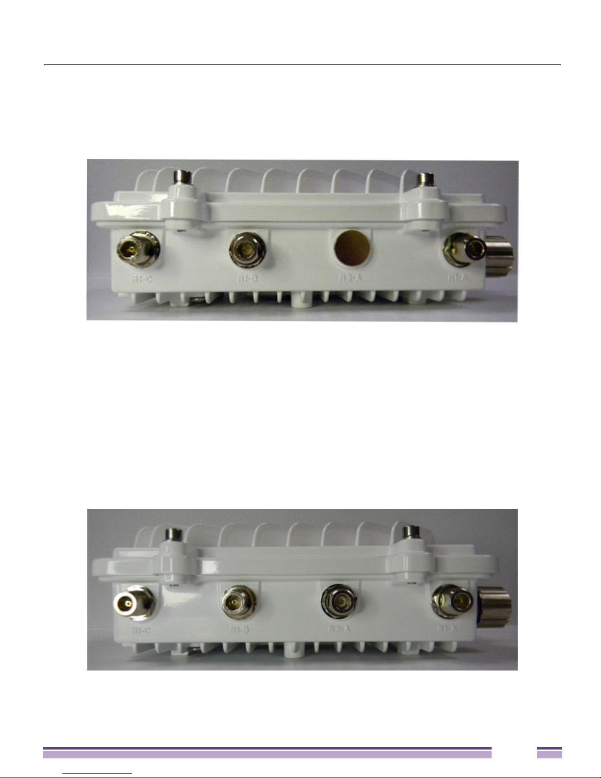
Altitude 4760 Access Point Antenna Connectors
The Altitude 4762 Series Access Point two radio models (15794, 15795, and 15811) are
configured with six N type male connectors to support two active WLAN data radios.
When mounting antennas to ports R1-A, R1-B, and R1-C, ensure that you have selected the
appropriate band for the configured radio that uses ports R1-A, R1-B, and R1-C. In this
instance, R1 ports relate to the software configured radio 1 settings.
When mounting antennas to connectors marked R2-A, R2-B and R2-C, these antenna ports
relate to the software settings of radio 2. Care must be taken to provide the correct antenna
for the operating band of each port.
Altitude 4763 Access Point three radio models (15796, 15910, and 15812) are configured with
eight N type connectors to support two active WLAN data radios and a dedicated sensor
radio as the third.
Altitude™ 4760 Series Access Point Installation Guide
17

Altitude 4760 Series Access Point Ports and Connections
As with the two radio models, R1 ports relate to the software configured radio 1 settings.
When mounting antennas to connectors marked R2-A, R2-B and R2-C, the antenna ports
relate to the software configured radio 2 settings. Care must be taken to provide the correct
antenna for the operating band of each port.
Ports R3-A and R3-B are reserved for the sensor radio. An appropriate multi-band antenna
should be mounted on the unit for sensor operation.
NOTE
The sensor radio does not function as a WLAN data radio.
WARNING!
Antenna ports where no antenna is mounted must be properly terminated using an approved
IP67 terminator.
Altitude™ 4760 Series Access Point Installation Guide
18
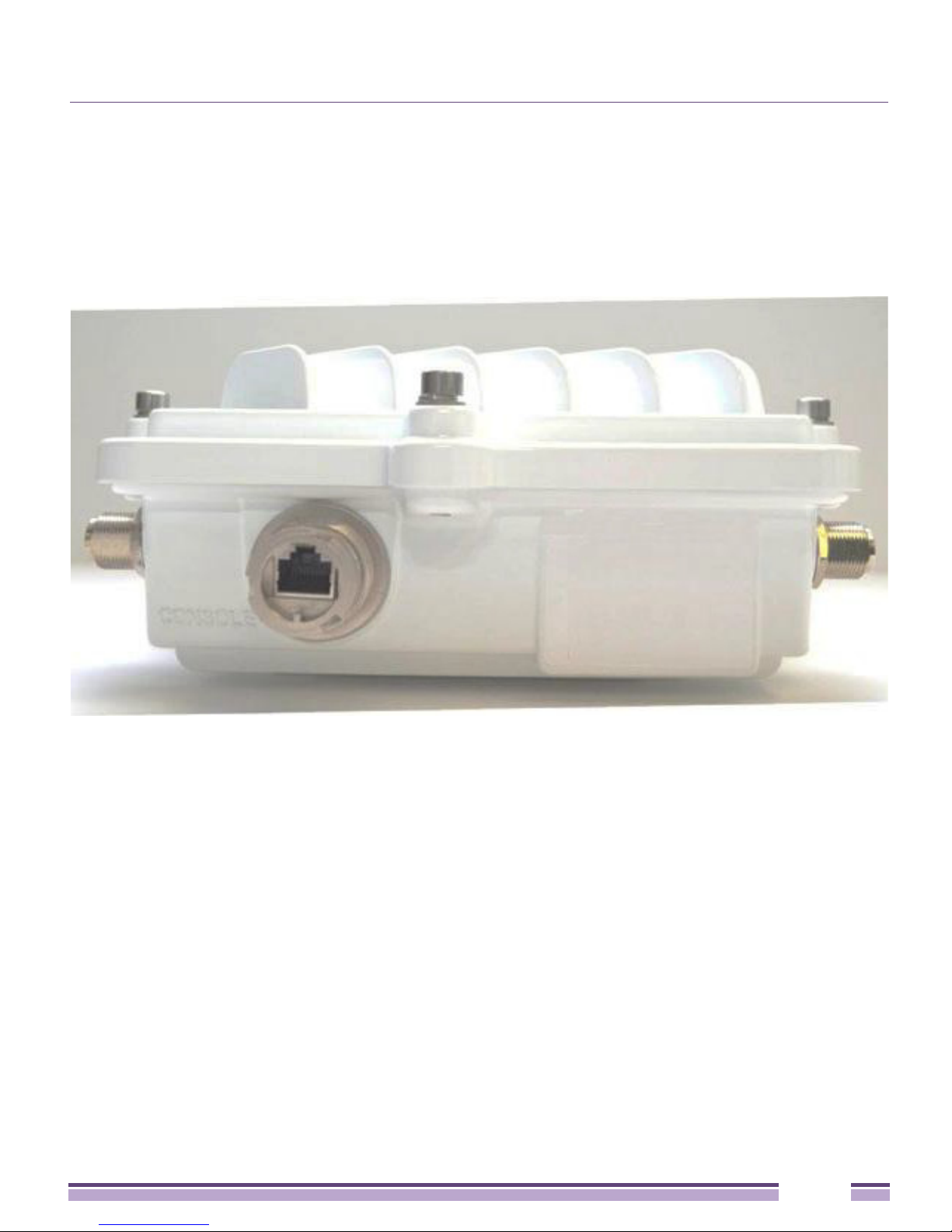
Altitude 4760 Series Access Point Ports and Connections
Altitude 4760 Series Access Point Console, GE1/POE
and GE2 Ports
The Altitude 4760 Series Access Point has Ethernet ports for external Console, GE1/POE,
and GE2 connections. To gain access to the ports you will need to remove the protective
caps.
Altitude™ 4760 Series Access Point Installation Guide
19
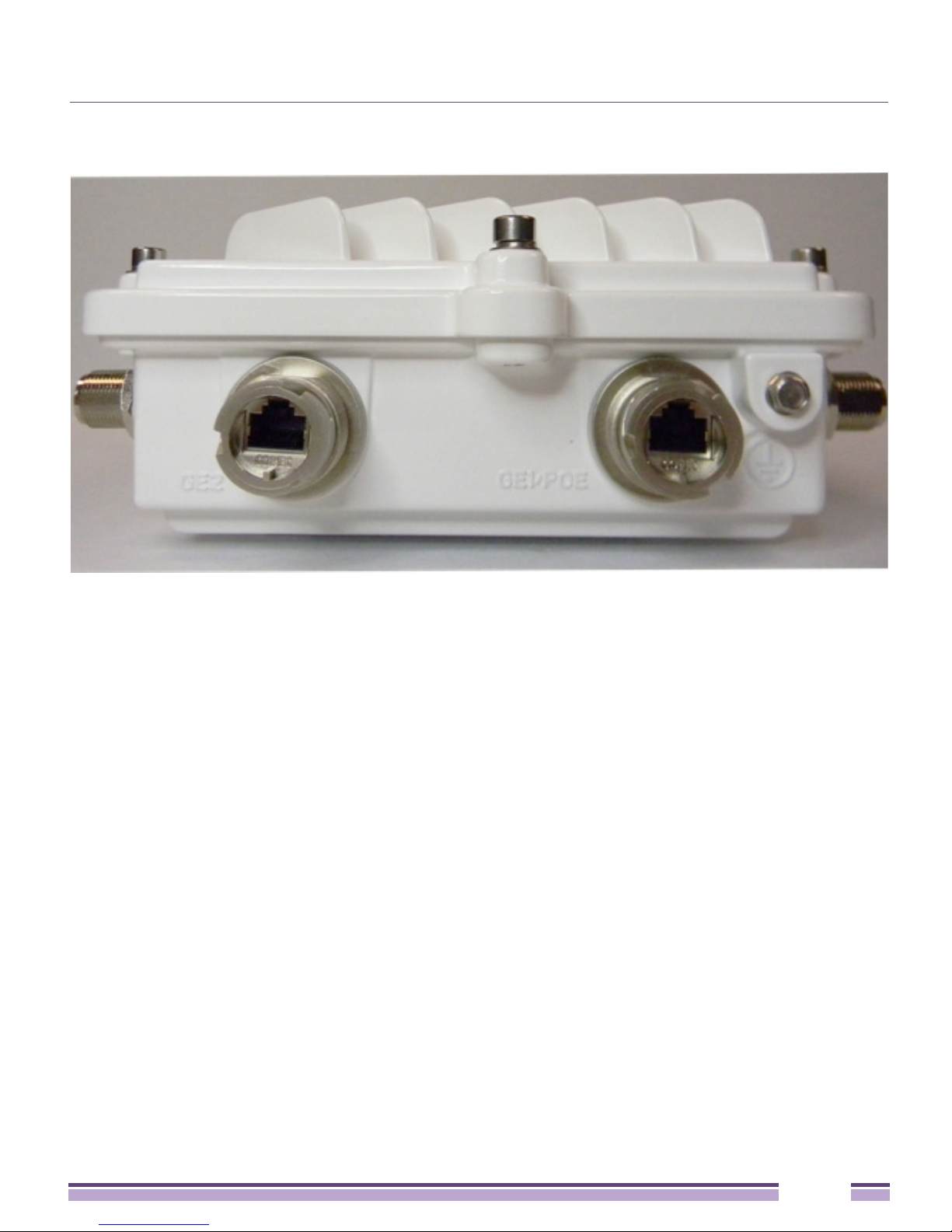
Altitude 4760 Series Access Point Ports and Connections
The Ethernet cable from the PoE device (if used) connects to the GE1/POE port on the unit.
The GE2 port on the unit can be used if a second data connection for an external device
(e.g. surveillance camera) is required. Ensure the GE2 WAN port has been configured to
permit an attached external device during the configuration process.
When making connections using these ports, a properly rated RJ45 connector is required.
One weatherproof RJ45 plug kit is provided with each Access Point. When connecting
cables to the Altitude 4760 Series Access Point Ethernet ports, follow the instructions in the
connector packaging and tighten the connectors to create a weatherproof seal. Shielded
cables are required.
Altitude™ 4760 Series Access Point Installation Guide
20
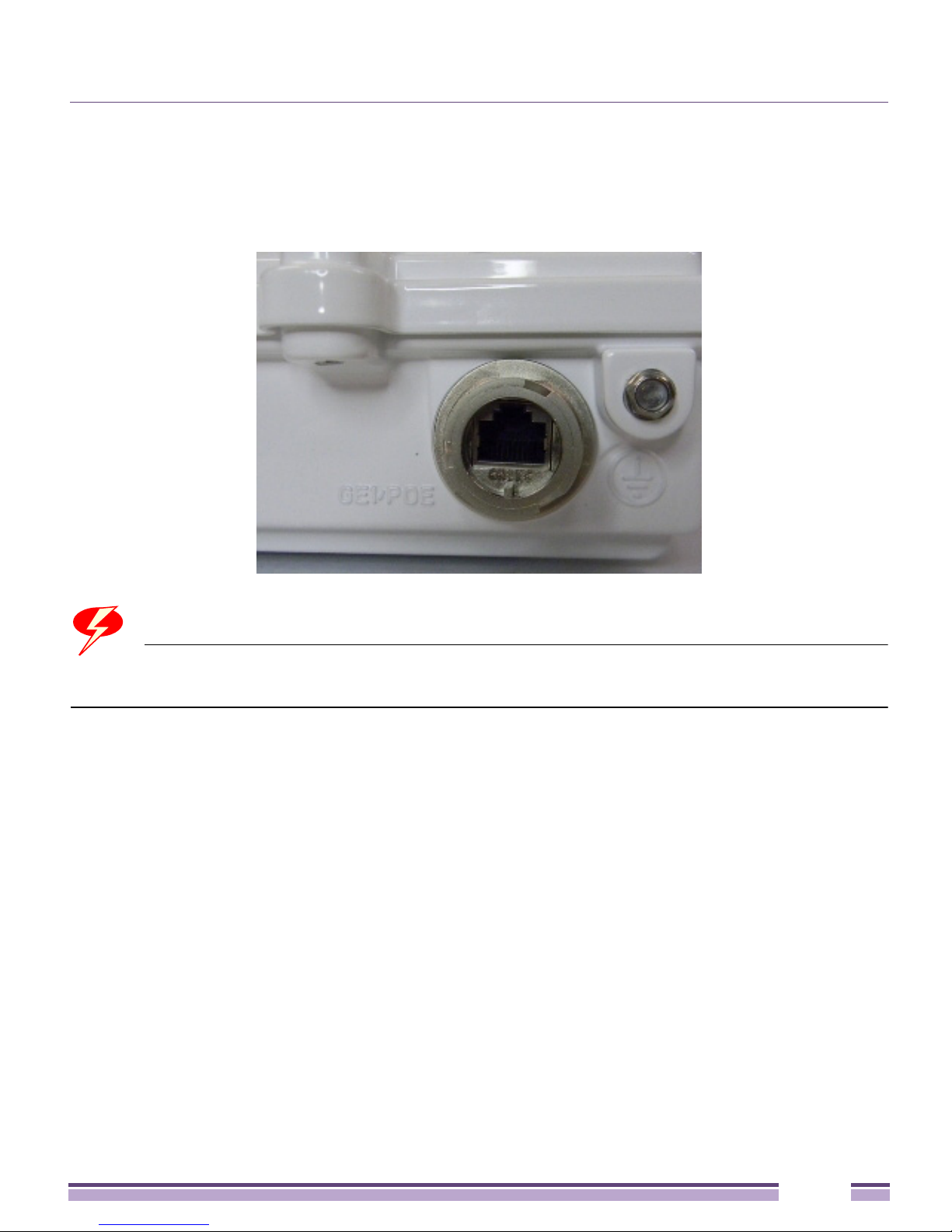
Altitude 4760 Series Access Point Ports and Connections
Altitude 4760 Series Access Point Grounding Screw
The grounding screw is located to the right of the GE1/POE port and above the GND
symbol.
WARNING!
The grounding cable for an Altitude 4760 Series Access Point must be at a minimum a #10
gauge wire cross section.
The grounding cable can be attached to the unit using one of three recommended methods.
Using an 8mm socket and driver:
●
Loosen the grounding screw and insert the grounding cable into the hole below it.
Tighten the grounding screw to 30 inch pounds (lbf-in).
●
Loosen the grounding screw and wind the grounding cable around the screw. Tighten
the grounding screw to 30 inch pounds (lbf-in).
●
Attach a ring lug to the grounding cable and remove the grounding screw to attach the
ring lug to the Access Point. Secure it to the unit by reinserting the grounding screw.
Tighten the grounding screw to 30 inch pounds (lbf-in).
Altitude™ 4760 Series Access Point Installation Guide
21

Altitude 4760 Series Access Point Ports and Connections
Altitude 4760 Series Access Point Factory Reset
Hardware Button
An Altitude 4760 Series Access Point can be physically reset using the hardware reset
button. The button is located inside the reset port on the bottom of the unit.
NOTE
This option is not supported by all Altitude 4760 Series Access Point software releases. Refer
to the release notes for the appropriate software.
The reset button is only enabled for a ten second interval as the unit boots up. It can be
accessed by removing the cover screw using a rachet driver and a #2 Phillips head adapter.
Push the button to reset the Access Point. Confirm that the reset cycle was completed and
replace the cover screw.
To perform an external hardware reset and restore the Access Point default settings:
1 Using a #2 phillips screwdriver, remove the cover screw from the external reset port.
2 Gently press and hold the reset button.
3 If any of LEDs 2 through 6 are active, it indicates that the unit has booted successfully
and the operational software is running.
Altitude™ 4760 Series Access Point Installation Guide
22

LED Indicators
LED Indicators
The Altitude 4760 Series Access Point has six LEDs on the top of the Access Point housing.
The Access Point utilizes two different colored lights below each LED. Only one light
displays within an LED at any given time. Every light within each LED is exercised during
startup to allow the user to see if an LED is not functioning. The LEDs turn on and off
while rotating in a circular pattern. Since two LEDs feed each light pipe, the pattern is from
left to right (LEDs 1 through 6), then right to left (LEDs 6 through 1).
The functionality and display of the top housing LEDs are shown in the following sections.
Altitude™ 4760 Series Access Point Installation Guide
23

LED Indicators
Two Radio LEDs
A dual-radio model Access Point (part numbers 15794, 15795, and 15811) has the following
unique LED behavior:
LED 1
(Sensor)
Not Used Blinking Emerald
LED 2
(2.4 GHz)
indicates
802.11b/g/n
activity.
Solid Emerald
indicates a radio
is present but not
configured.
LED 3
(5 GHz)
Blinking Amber
indicates
802.11a/n
activity.
Solid Amber
indicates a
radio is present
but not
configured.
LED 4
(GE2/WAN)
LED Off
indicates the
port is not
connected.
Blinking Green
indicates
normal
operation.
Rapidly
blinking Yellow
indicates a
port error.
LED 5
(GE1/LAN)
LED Off
indicates the
port is not
connected.
Blinking Green
indicates
normal
operation.
Rapidly
blinking Yellow
indicates a
port error.
LED 6
(System)
Solid Red
indicates
diagnostic
mode.
Blinking Red at
1 second
interval
indicates POST
failure.
Solid White
following
diagnostic mode
indicates
booting.
Blinking Red
and White at 1
second interval
indicates “no
adoption”.
WARNING!
If LED 6 remains blinking Red for longer than 10 minutes, cycle the power to the unit. If the
condition persists, contact the Extreme Networks support center.
Altitude™ 4760 Series Access Point Installation Guide
Solid White
indicates normal
operation.
24

LED Indicators
Three Radio LEDs
A tri-radio Access Point with sensor (part numbers 15796, 15910, and 15812) has the
following unique LED behavior:
LED 1
(Sensor)
Blinking
Emerald and
Amber at 2
second interval
indicates a
radio is present
but not
connected to a
server.
Solid Amber
indicates a
radio is present
and connected
to a server.
LED 2
(2.4 GHz)
Blinking
Emerald
indicates
802.11b/g/n
activity.
Solid Emerald
indicates a
radio is present
but not
configured.
LED 3
(5 GHz)
Blinking Amber
indicates
802.11a/n
activity.
Solid Amber
indicates a
radio is present
but not
configured.
LED 4
(GE2/WAN)
LED Off
indicates the
port is not
connected.
Blinking Green
indicates
normal
operation.
Rapidly
blinking Yellow
indicates a
port error.
LED 5
(GE1/LAN)
LED Off
indicates the
port is not
connected.
Blinking Green
indicates
normal
operation.
Rapidly
blinking Yellow
indicates a
port error.
LED 6
(System)
Solid Red
indicates
diagnostic
mode.
Blinking Red at
1 second
interval
indicates POST
failure.
Solid White
following
diagnostic
more indicates
booting.
Blinking Red
and White at 1
second interval
indicates “no
adoption”.
Altitude™ 4760 Series Access Point Installation Guide
Solid White
indicates
normal
operation.
25
Altitude 4760 Series Access Point Hardware Mounting and Installation
Altitude 4760 Series Access Point Hardware
Mounting and Installation
It is recommended to use the Altitude 4760 Series Access Point mounting bracket kit
(KT-147407-01) for most deployments. When a standoff distance is required for a pole
mounted or wall mounted installation, use the extension arm kit (KT-150173-01).
The following sections detail the installation procedure for deploying an
4760 Series Access Point
:
Altitude
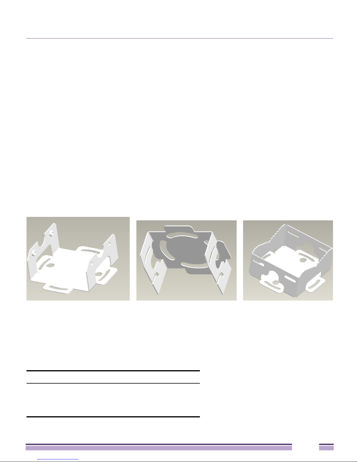
Mounting Bracket Kit
The Altitude 4760 Series Access Point mounting bracket kit (KT-147407-01) includes the
Access Point Bracket (left), Angle Adapter Bracket (center), and Pole Mount Bracket (right)
sections.
The Access Point Bracket and the Angle Adapter Bracket can be adjusted to rotate (plus or
minus 15 degrees) and tilt (up to 45 degrees) during installation to orient the unit for
optimal positioning.
The following ancillary hardware to assemble the mounting bracket sections is included in
the kit.
Description Quantity
M6 serrated hex flanged screws 8
1/2 inch hex head nut 2
1/2 inch x 3/4 inch hex head bolt 2
Altitude™ 4760 Series Access Point Installation Guide
26
 Loading...