

Extreme Networks Altitude 4532 Series Installation Manual

Altitude™ 4532 Series Access Point
Installation Guide
Extreme Networks, Inc.
3585 Monroe Street
Santa Clara, California 95051
(888) 257-3000
(408) 579-2800
http://www.extremenetworks.com
Published: October 2012
Part number: 120791-00 Rev 02

AccessAdapt, Alpine, Altitude, BlackDiamond, EPICenter, ExtremeWorks Essentials, Ethernet
Everywhere, Extreme Enabled, Extreme Ethernet Everywhere, Extreme Networks, Extreme Standby
Router Protocol, Extreme Turbodrive, Extreme Velocity, ExtremeWare, ExtremeWorks, ExtremeXOS, Go
Purple Extreme Solution, ExtremeXOS ScreenPlay, ReachNXT, Sentriant, ServiceWatch, Summit,
SummitStack, Triumph, Unified Access Architecture, Unified Access RF Manager, UniStack, the
Extreme Networks logo, the Alpine logo, the BlackDiamond logo, the Extreme Turbodrive logo, the
Summit logos, and the Powered by ExtremeXOS logo are trademarks or registered trademarks of
Extreme Networks, Inc. or its subsidiaries in the United States and/or other countries.
sFlow is a registered trademark of InMon Corporation.
Specifications are subject to change without notice.
All other registered trademarks, trademarks, and service marks are property of their respective
owners.
© 2012 Extreme Networks, Inc. All Rights Reserved.
2
Altitude™ 4532 Series Access Point Installation Guide

Table of Contents
Chapter 1: Introduction....................................................................................................5
Document Conventions...............................................................................................................6
Warnings..................................................................................................................................... 6
Site Preparation.......................................................................................................................... 7
Altitude 4532 Access Point Package Contents........................................................................... 7
External Antenna Model Package Contents........................................................................7
Integrated Antenna Model Package Contents.....................................................................7
Features...................................................................................................................................... 8
Chapter 2: Hardware Installation ....................................................................................9
Installation Instructions ............................................................................................................... 9
Precautions............................................................................................................................... 10
Access Point Placement ........................................................................................................... 11
Integrated Antenna Model Wall Mount Instructions .................................................................. 11
Wall Mount Hardware ........................................................................................................ 11
Wall Mount Procedure ....................................................................................................... 13
Integrated Antenna Model Suspended Ceiling
T-Bar Mount Instructions........................................................................................................... 15
Suspended Ceiling Mount Procedure................................................................................ 15
External Antenna Model Wall Mount Instructions ..................................................................... 16
Wall Mount Hardware ........................................................................................................ 16
Wall Mount Procedure ....................................................................................................... 17
External Antenna Model Suspended Ceiling Tile (Plenum) Mount Instructions........................ 18
Suspended Ceiling Mount Hardware................................................................................. 19
Ceiling Mount Procedure ...................................................................................................19
Antenna Options for Altitude 4532 Access Point External Antenna.......................................... 20
LED Indicators .......................................................................................................................... 21
Chapter 3: Defining A Basic Configuration..................................................................22
Using the Initial Setup Wizard...................................................................................................22
Chapter 4: Specifications ..............................................................................................45
Altitude 4532 Access Point External Antenna Model Electrical Characteristics ....................... 45
Altitude 4532 Access Point External Antenna Model Physical Characteristics......................... 45
Altitude™ 4532 Series Access Point Installation Guide
3

Table of Contents
Altitude 4532 Access Point Integrated Antenna Model Electrical Characteristics .................... 46
Altitude 4532 Access Point Integrated Antenna Model Physical Characteristics...................... 46
Radio Characteristics................................................................................................................ 47
Chapter 5: Regulatory Information ...............................................................................48
Regulatory Information.............................................................................................................. 48
Wireless Device Country Approvals.......................................................................................... 48
Country Selection .............................................................................................................. 49
Frequency of Operation – FCC and IC.............................................................................. 49
Health and Safety Recommendations ...................................................................................... 50
Warnings for Use of Wireless Devices .............................................................................. 50
Potentially Hazardous Atmospheres – Fixed Installations................................................. 50
Safety in Hospitals.............................................................................................................50
Pacemakers....................................................................................................................... 50
Other Medical Devices....................................................................................................... 51
RF Exposure Guidelines...........................................................................................................51
Safety Information ............................................................................................................. 51
International.............................................................................................................................. 51
Europe ...................................................................................................................................... 51
US and Canada ........................................................................................................................ 52
Power Supply............................................................................................................................52
Radio Frequency Interference Requirements – FCC................................................................ 53
Radio Frequency Interference Requirements – Canada ......................................................... 53
Radio Transmitters ............................................................................................................ 54
CE Marking and European Economic Area (EEA).................................................................... 54
Statement of Compliance.......................................................................................................... 55
Waste Electrical and Electronic Equipment (WEEE) ................................................................ 55
Japan (VCCI) - Voluntary Control Council for Interference....................................................... 57
Class B ITE ....................................................................................................................... 57
Korea Warning Statement for Class B ITE ............................................................................... 57
Other Countries ........................................................................................................................58
Australia............................................................................................................................. 58
Brazil.................................................................................................................................. 58
Chile ..................................................................................................................................58
China ................................................................................................................................. 59
Mexico ............................................................................................................................... 59
South Korea....................................................................................................................... 59
Taiwan .............................................................................................................................. 60
Chapter 6: Customer Support .......................................................................................61
Registration............................................................................................................................... 61
Documentation.......................................................................................................................... 62
4
Altitude™ 4532 Series Access Point Installation Guide

Introduction
1
CHAPTER
The Altitude™ 4532 Access Point, a component of the Extreme Networks® Wireless
Mobility System, links wireless 802.11a/b/g/n devices to the Summit
Controller, enabling growth of your wireless network with a cost effective alternative to
standard Access Points. The Altitude 4532 Access Point provides two placement options:
wall and ceiling. Wall mount slots fit onto two provided screws. Arrows on the case guide
the placement of the screws. For placement above a suspended ceiling, a safety wire tie
point on the case provides for a safety wire loop. The light pipe fits through a hole in the
ceiling tile to provide a view of the unit’s status lights.
The Altitude 4532 Access Point receives all power and transfers data through the same
CAT-5 or better Ethernet cable. There is no additional power supply required. An 802.3af
Ethernet controller or Power Injector is required.
®
WM3000 Series
Altitude™ 4532 Series Access Point Installation Guide
5

Chapter 1: Introduction
Document Conventions
The following graphical alerts are used in this document to indicate notable situations:
NOTE
Tips, hints, or special requirements that you should take note of.
CAUTION
Care is required. Disregarding a caution can result in data loss or equipment malfunction.
WARNING!
Indicates a condition or procedure that could result in personal injury or equipment damage.
Warnings
●
Read all installation instructions and site survey reports, and verify correct equipment
installation before connecting the Altitude 4532 Access Point.
●
Remove jewelry and watches before installing this equipment.
●
Verify that the unit is grounded before connecting it to the power source.
●
Verify that any device connected to this unit is properly wired and grounded.
●
Verify there is adequate ventilation around the device, and that ambient temperatures
meet equipment operation specifications.
6
Altitude™ 4532 Series Access Point Installation Guide

Site Preparation
Site Preparation
●
Consult your site survey and network analysis reports to determine specific equipment
placement, power drops, and so on.
●
Assign installation responsibility to the appropriate personnel.
●
Identify and document where all installed components are located.
●
Ensure adequate, dust-free ventilation to all installed equipment.
●
Identify and prepare Ethernet and console port connections.
●
Verify that cable lengths are within the maximum allowable distances for optimal signal
transmission.
Altitude 4532 Access Point Package Contents
The Altitude 4532 Access Point is available in integrated antenna and external antenna
models. The contents of the package differ between the integrated antenna and external
antenna model.
External Antenna Model Package Contents
●
Altitude 4532 Access Point with external antenna connectors (Plenum Rated)
●
Two wall mount screws
●
Two wall anchors
●
Light pipe
●
Badge for light pipe
●
Altitude 4532 Access Point Installation Guide (This Guide)
Integrated Antenna Model Package Contents
●
Altitude 4532 Access Point with integrated antennas
●
Two wall mount screws
●
Two wall anchors
●
Altitude 4532 Access Point Installation Guide (This Guide)
Altitude™ 4532 Series Access Point Installation Guide
7

Chapter 1: Introduction
Features
●
One RJ-45 connector
●
LED indicators
●
Safety wire tie point
●
Slots for wall mounting
●
Clips for mounting on a suspended ceiling T-bar
●
Lock port for Kensington® style Security Lock
The Altitude 4532 Access Point has one RJ-45 connector supporting an 10/100/1000
Ethernet port and requires 802.3af-compliant power from an external source.
NOTE
When operating in a Gigabit Ethernet environment, CAT-5e or CAT-6 cable is recommended
for Gigabit operation.
The Altitude 4532 Access Point comes with dual radios both supporting 802.11a/b/g/n.
The Access Point contains runtime firmware which enables the unit to boot after a power
up or watchdog reset. The runtime firmware on the Access Point and the firmware
downloaded from the controller can be updated via the Ethernet interface from the Wireless
Controller.
8
Altitude™ 4532 Series Access Point Installation Guide

Hardware Installation
2
CHAPTER
Installation Instructions
The Altitude 4532 Access Point mounts either on a wall (with wide-shoulder screws) or on a
suspended ceiling T-bar. This unit is not designed for mounting on a desk.
To prepare for the installation, perform the following:
1 Match the model number on the purchase order with the model numbers in the packing
list and on the case of the device shipped.
2 Verify the contents of the box include the intended Altitude 4532 Access Point and that
the included hardware matches the package contents on page 2.
Part
SKU
AP4532i-US 15764 Altitude AP4532i dual-radio Independent indoor Access Point for US
AP4532i-ROW 15765 Altitude AP4532i dual-radio Independent indoor Access Point for the
AP4532i-EU 15798 Altitude AP4532i dual-radio Independent indoor Access Point for the
AP4532e-US 15767 Altitude AP4532e dual-radio Independent indoor Access Point for US
Altitude™ 4532 Series Access Point Installation Guide
Number Description
regulatory domain, 802.11a/b/g/n, 2x3 MIMO, Includes internal
omnidirectional antennas, Powered by 802.3af/at PoE or by use of a
PoE injector.
Rest of the World regulatory domain, 802.11a/b/g/n, 2x3 MIMO,
Includes internal omni-directional antennas, Powered by 802.3af/at
PoE or by use of a PoE injector.
European Union regulatory domain, 802.11a/b/g/n, 2x3 MIMO,
Includes internal omni-directional antennas, Powered by 802.3af/at
PoE or by use of a PoE injector.
regulatory domain, 802.11a/b/g/n, 2x3 MIMO. External antennas not
included-must order separately up to 6 paddle antennas. Powered by
802.3af/at PoE or by use of a PoE injector.
9

Precautions
Part
SKU
AP4532e-ROW 15768 Altitude AP4532e dual-radio Independent indoor Access Point for the
AP4532e-EU 15799 Altitude AP4532e dual-radio Independent indoor Access Point for the
NOTE
In the above SKU numbers, "US" represents the United States regulatory model, and "ROW"
represents the Rest of World regulatory model.
Number Description
Rest of the World regulatory domain, 802.11a/b/g/n, 2x3 MIMO.
External antennas not included-must order separately up to 6 paddle
antennas. Powered by 802.3af/at PoE or by use of a PoE injector.
European Union regulatory domain, 802.11a/b/g/n, 2x3 MIMO. External
antennas not included-must order separately up to 6 paddle antennas.
Powered by 802.3af/at PoE or by use of a PoE injector.
3 Review site survey and network analysis reports to determine the location and mounting
position for the Altitude 4532 Access Point.
4 Connect a CAT-5 or better Ethernet cable to a compatible 802.3af power source and run
the cable to the installation site. Ensure there is sufficient slack on the cable to perform
the installation steps.
NOTE
When operating in a Gigabit Ethernet environment, CAT-5e or CAT-6 cable is recommended
for Gigabit operation.
Precautions
Before installing an Altitude 4532 Access Point, verify the following:
●
Extreme Networks recommends that you do not install the Altitude 4532 Access Point in
wet or dusty areas.
●
Verify that the environment has a continuous temperature range between 0° C to 50° C.
Altitude™ 4532 Series Access Point Installation Guide
10

Access Point Placement
Access Point Placement
For optimal performance, install the Access Point away from transformers, heavy-duty
motors, fluorescent lights, microwave ovens, refrigerators, and other industrial equipment.
Signal loss can occur when metal, concrete, walls, or floors block transmission. Install the
Access Point in an open area or add Access Points as needed to improve coverage.
Antenna coverage is analogous to lighting. Users might find an area lit from far away to be
not bright enough. An area lit sharply might minimize coverage and create dark areas.
Uniform antenna placement in an area (like even placement of a light bulb) provides even,
efficient coverage.
Place the Access Point using the following guidelines:
●
Install the Access Point at an ideal height of 10 feet from the ground.
●
Orient the Access Point antennas vertically for best reception.
To maximize the Access Point’s radio coverage area, Extreme Networks recommends
conducting a site survey to define and document radio interference obstacles before
installing the Access Point.
Integrated Antenna Model Wall Mount
Instructions
This mounting requires hanging the Altitude 4532 Access Point along its width or length
using the two slots on the bottom of the unit. The Altitude 4532 Access Point can be
mounted onto any plaster, wood, or cement wall surface using the provided wall anchors.
The following illustration displays a lengthwise mount.
Wall Mount Hardware
●
Two wide-shoulder Phillips pan head self-tapping screws
●
Two wall anchors
●
Security cable (optional)
Altitude™ 4532 Series Access Point Installation Guide
11

Integrated Antenna Model Wall Mount Instructions
NOTE
In the event that the original mounting screws are lost, the following screws can be used
instead: (ANSI Standard) #6-18 X 0.875in. Type A or AB Self-Tapping Screw, or (ANSI Standard
Metric) M3.5 X 0.6 X 20mm Type D Self-Tapping Screw.
Altitude™ 4532 Series Access Point Installation Guide
12
Integrated Antenna Model Wall Mount Instructions
Wall Mount Procedure
Integrated Antenna Wall Mount
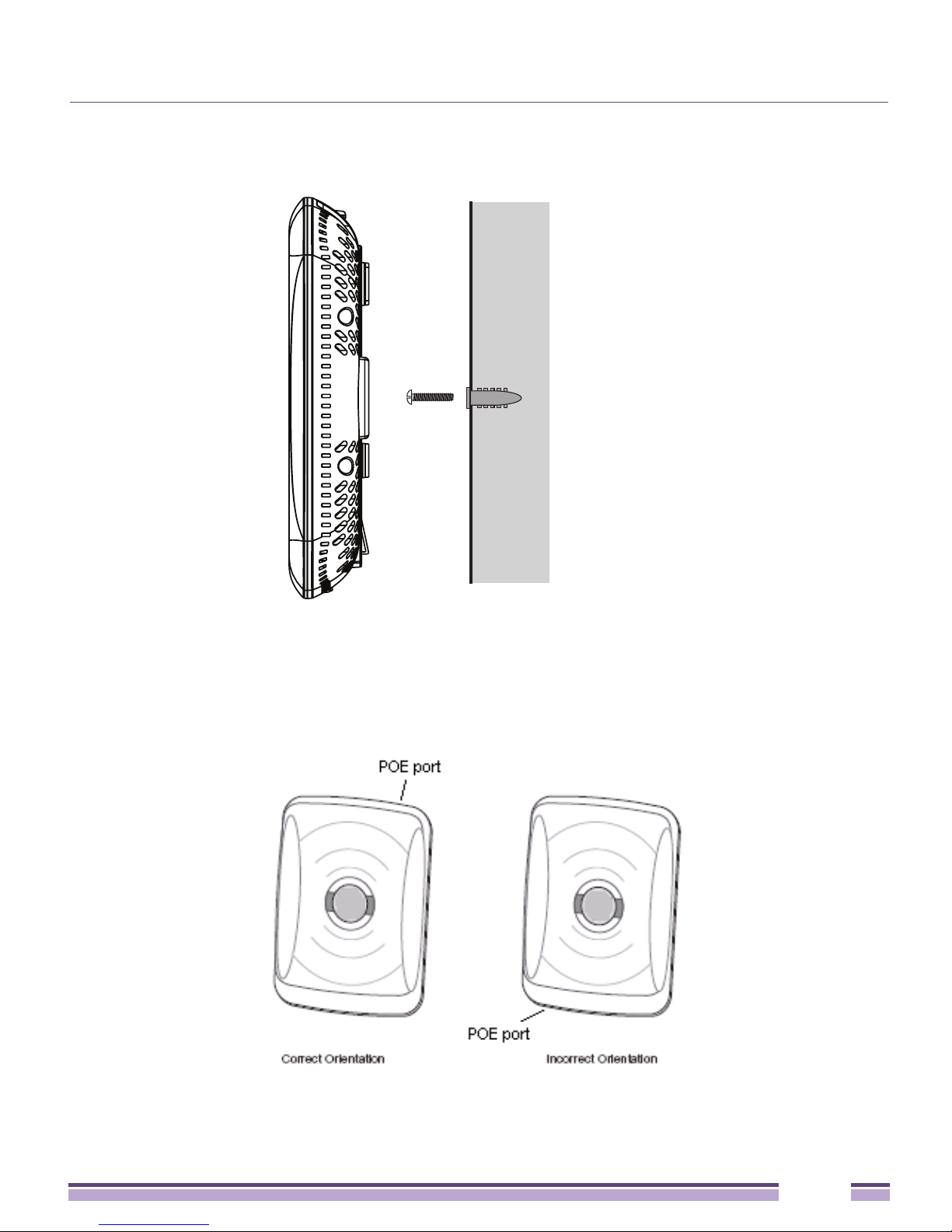
1 Orient the case on the wall by its width or length.
Altitude™ 4532 Series Access Point Installation Guide
13

Integrated Antenna Model Wall Mount Instructions
CAUTION
To ensure proper operation of the Altitude 4532 Access Point, ensure that it is mounted
with the logo facing upwards.
2 Using the arrows on one edge of the case as guides, move the edge to the midline of the
mounting area and mark points on the midline for the screws.
3 At each point, drill a hole in the wall, insert an anchor, screw into the anchor the wall
mounting screw and stop when there is 1mm between the screw head and the wall
NOTE
When pre-drilling a hole, the recommended hole size is 2.8mm (0.11in.) if the screws are
going directly into the wall and 6mm (0.23in.) if the provided wall anchors are being used.
.
4 If required, install and attach a security cable to the unit’s lock port.
5 Attach the Ethernet cable to the unit and to a controller with an 802.3af-compatible
power source.
6 Place the middle of each of the case’s mount slots over the screw heads.
7 Slide the case down along the mounting surface to hang the mount slots on the screw
heads.
8 Verify that the unit has power by observing that the LEDs are lit or flashing.
Altitude™ 4532 Series Access Point Installation Guide
14
Integrated Antenna Model Suspended Ceiling T-Bar Mount Instructions
Integrated Antenna Model Suspended Ceiling
T-Bar Mount Instructions
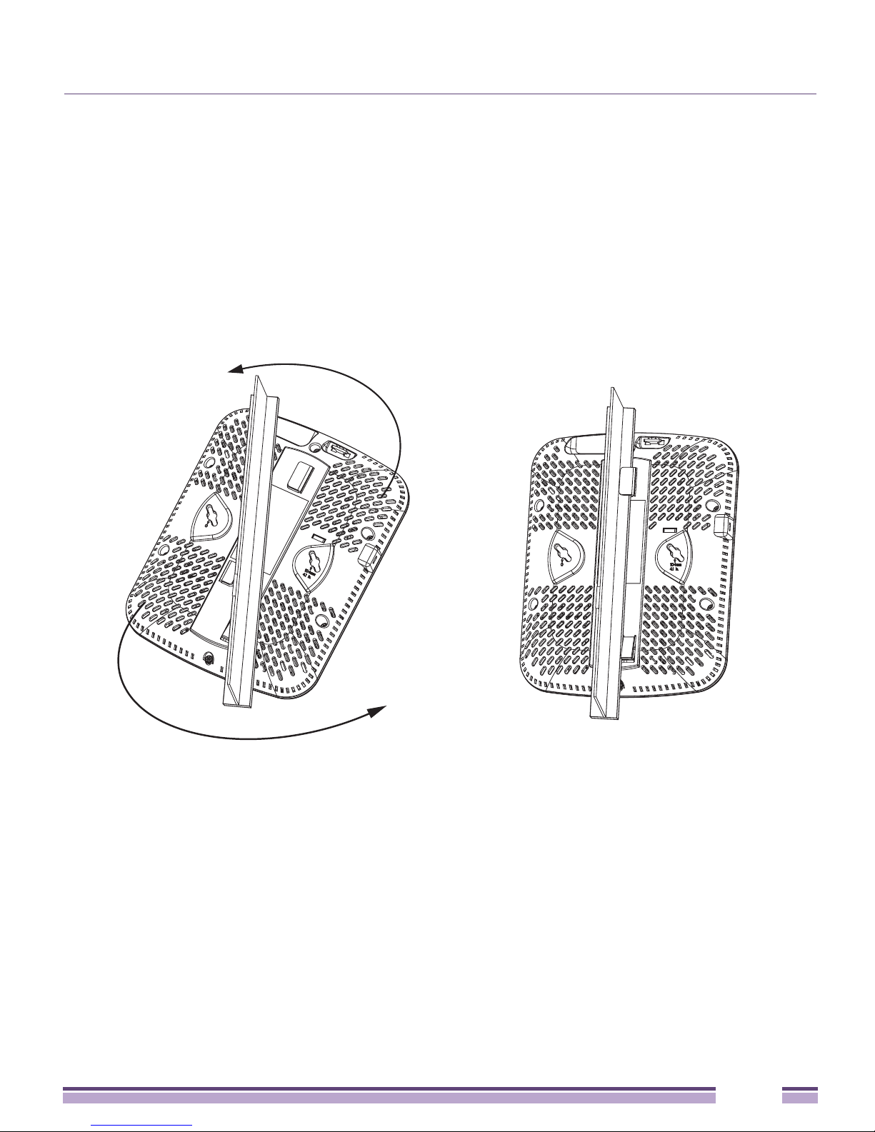
Ceiling mount requires holding the Altitude 4532 Access Point up against a T-bar of a
suspended ceiling grid and twisting the case onto the T-bar.
Suspended Ceiling Mount Procedure
1 If required, install and attach a security cable to the unit’s lock port.
2 Plug the Ethernet cable into the unit and to a controller with an 802.3af compatible
power source.
3 Align the bottom of the T-bar with the back of the case.
4 Orient the case by its length, and the length of the T-bar.
5 Rotate the case 45 degrees clockwise, or about 10 o’clock.
6 Push the back of the case onto the bottom of the T-bar.
7 Rotate the case 45 degrees counter-clockwise. The clips click as they fasten to the T-bar.
8 Verify the unit has power by observing the LEDs.
Altitude™ 4532 Series Access Point Installation Guide
15

External Antenna Model Wall Mount Instructions
External Antenna Model Wall Mount
Instructions
Wall mounting requires hanging the Altitude 4532 Access Point along its width or length
using the pair of slots on the bottom of the unit. The Altitude 4532 Access Point can be
mounted onto any plaster, wood, or cement wall surface using the provided wall anchors.
Wall Mount Hardware
●
Two wide-shoulder Phillips pan head self-tapping screws
●
Two wall anchors
●
Safety wire (recommended) and security cable (optional)
NOTE
In the event that the original mounting screws are lost, the following screws can be used:
(ANSI Standard) #6-18 X 0.875in. Type A or AB Self-Tapping Screw, or (ANSI Standard Metric) M3.5
X 0.6 X 20mm Type D Self-Tapping Screw.
Altitude™ 4532 Series Access Point Installation Guide
16
External Antenna Model Wall Mount Instructions
Wall Mount Procedure
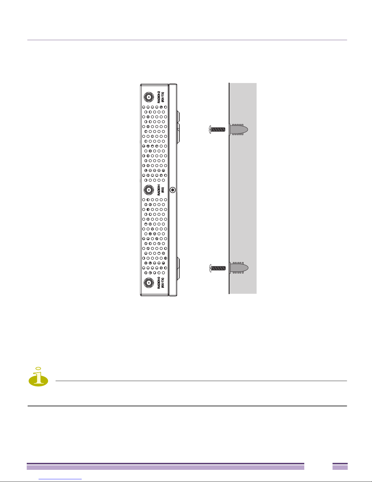
1 Orient the case on the wall by its width or length.
2 Using the arrows on one edge of the case as guides, move the edge to the midline of the
mounting area and mark points on the midline for the screws.
3 At each point, drill a hole in the wall, insert an anchor, screw into the anchor the wall
mounting screw and stop when there is 1mm between the screw head and the wall.
NOTE
The recommended hole size is 2.8mm (0.11in.) if the screws are going directly into the wall,
and 6mm (0.23in.) if the provided wall anchors are being used.
4 If required, loop a safety wire, between 1.5mm (.06in.) and 2.5mm (.10in.) in diameter,
around the tie post and secure the loop.
Altitude™ 4532 Series Access Point Installation Guide
17

External Antenna Model Suspended Ceiling Tile (Plenum) Mount Instructions
5 If required, install and attach a security cable to the unit’s lock port.
6 Place the large corner of each of the case’s mount slots over the screw heads.
7 Slide the case down along the mounting surface to hang the mount slots on the screw
heads.
8 Attach appropriate antennas to the connectors.
9 Attach the Ethernet cable to the unit and to a controller with an 802.3af compatible
power source.
10 Verify the unit has power by observing that the LEDs are lit or flashing.
External Antenna Model Suspended Ceiling Tile
(Plenum) Mount Instructions
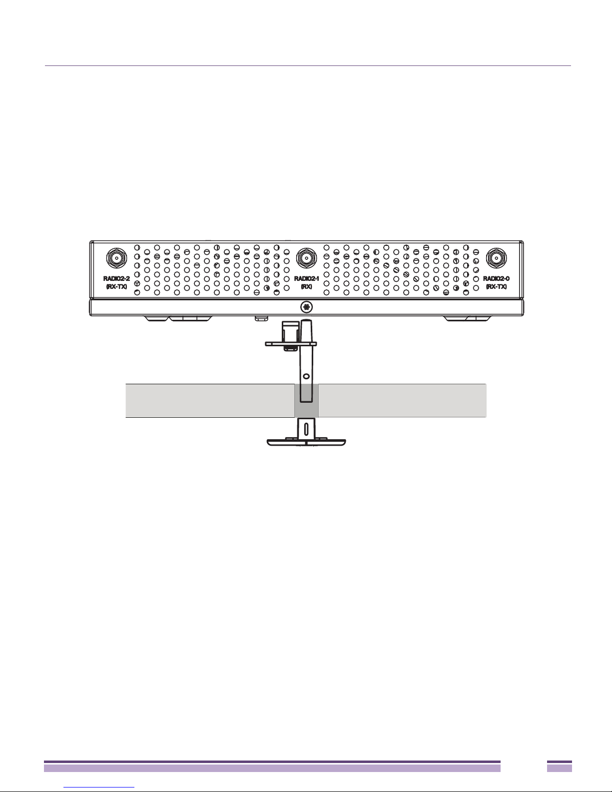
Ceiling mount requires placing the Altitude 4532 Access Point above a suspended ceiling
and installing the provided light pipe for viewing the status lights of the unit.
NOTE
Notes or warnings about suspended ceiling mounts apply to all installations where the unit is
placed on suspended ceiling tile. The case has a safety wire tie point for a standard safety wire.
CAUTION
Extreme Networks does not recommend mounting the Altitude 4532 Access Point directly to
any suspended ceiling tile with a thickness less than 12.7mm (0.5in.) or a suspended ceiling tile with
an unsupported span greater than 660mm (26in.). Extreme Networks strongly recommends fitting the
Altitude 4532 Access Point with a safety wire suitable for the specific installation. The safety wire
should be a standard ceiling suspension cable or equivalent steel wire between 1.59mm (.062in.) and
2.5mm (.10in.) in diameter.
This placement requires installation of the provided light pipe for viewing the status lights
of the unit.
Altitude™ 4532 Series Access Point Installation Guide
18
External Antenna Model Suspended Ceiling Tile (Plenum) Mount Instructions
Suspended Ceiling Mount Hardware
●
Light pipe
●
Badge for light pipe
●
Safety wire (recommended) and security cable (optional)
Ceiling Mount Procedure
Light Pipe
Ceiling Tile
Badge
1 If possible, remove the ceiling tile from its frame and place it, finished side down, on a
work surface.
2 If required, install a safety wire, between 1.5mm (.06in.) and 2.5mm (.10in.) in diameter,
in the ceiling space.
3 If required, install and attach a security cable to the unit’s lock port.
4 Mark a point on the upper or unfinished side of the tile.
5 Push the light pipe through the tile at the mark and remove the light pipe. If necessary,
use a drill to make a hole in the tile.
6 Attach appropriate antennas to the connectors.
7 Snap the clips of the light pipe into the bottom of the case.
8 Fit the light pipe into hole in the tile from its unfinished side.
9 Attach any safety wire to the safety wire tie point or security cable to the unit’s lock
port.
10 Bring the tile into the ceiling space.
Altitude™ 4532 Series Access Point Installation Guide
19
 Loading...