

Extreme Networks Altitude™ 4522 Series Installation Manual

Altitude™ 4522 Series Access Point
Installation Guide
Extreme Networks, Inc.
3585 Monroe Street
Santa Clara, California 95051
(888) 257-3000
(408) 579-2800
http://www.extremenetworks.com
Published: April 2013
Part number: 120795-00 Rev 01

AccessAdapt, Alpine, Altitude, BlackDiamond, EPICenter, ExtremeWorks Essentials, Ethernet
Everywhere, Extreme Enabled, Extreme Ethernet Everywhere, Extreme Networks, Extreme Standby
Router Protocol, Extreme Turbodrive, Extreme Velocity, ExtremeWare, ExtremeWorks, ExtremeXOS, Go
Purple Extreme Solution, ExtremeXOS ScreenPlay, ReachNXT, Sentriant, ServiceWatch, Summit,
SummitStack, Triumph, Unified Access Architecture, Unified Access RF Manager, UniStack, the
Extreme Networks logo, the Alpine logo, the BlackDiamond logo, the Extreme Turbodrive logo, the
Summit logos, and the Powered by ExtremeXOS logo are trademarks or registered trademarks of
Extreme Networks, Inc. or its subsidiaries in the United States and/or other countries.
sFlow is a registered trademark of InMon Corporation.
Specifications are subject to change without notice.
All other registered trademarks, trademarks, and service marks are property of their respective
owners.
© 2013 Extreme Networks, Inc. All Rights Reserved.
2
Altitude™ 4522 Series Access Point Installation Guide

Table of Contents
Chapter 1: Introduction....................................................................................................6
Document Conventions...............................................................................................................7
Warnings..................................................................................................................................... 7
Site Preparation.......................................................................................................................... 8
Package Contents ......................................................................................................................8
External Antenna Model Package Contents........................................................................8
Internal Antenna Model Package Contents.........................................................................8
Features .............................................................................................................................. 9
Chapter 2: Hardware Installation ..................................................................................10
Installation Instructions ............................................................................................................. 10
Precautions............................................................................................................................... 11
Access Point Placement ........................................................................................................... 11
Integrated Antenna Model Wall Mount Instructions .................................................................. 12
Wall Mount Hardware ........................................................................................................ 12
Wall Mount Procedure ..............................................................................................................13
Integrated Antenna Model Suspended Ceiling
T-Bar Mount.............................................................................................................................. 16
Suspended Ceiling T-Bar Mount Procedure...................................................................... 16
External Antenna Model Wall Mount Instructions ..................................................................... 17
Wall Mount Hardware ........................................................................................................ 17
Wall Mount Procedure - New Installation........................................................................... 18
Wall Mount Procedure - Existing Access Point Replacement ........................................... 19
External Antenna Model Suspended Ceiling T-Bar Mount ....................................................... 20
Suspended Ceiling T-Bar Mount Procedure - Using Mounting Kit..................................... 20
Suspended Ceiling T-Bar Mount Procedure - Using Ceiling Mount Hardware.................. 21
External Antenna Suspended Ceiling Tile (Plenum) Mount...................................................... 22
Suspended Ceiling Mount Hardware................................................................................. 23
Ceiling Mount Procedure ...................................................................................................23
Altitude 4522 Access Point External Antenna Model Antenna Options.................................... 23
LED Indicators .......................................................................................................................... 25
Altitude™ 4522 Series Access Point Installation Guide
3

Table of Contents
Chapter 3: Initial Access Point Configuration .............................................................27
Chapter 4: Specifications ..............................................................................................49
Altitude 4522 Access Point Integrated Antenna Model Electrical Characteristics .................... 49
Altitude 4522 Access Point Integrated Antenna Model Physical Characteristics...................... 49
Altitude 4522 Access Point External Antenna Model Electrical Characteristics ....................... 50
Altitude 4522 Access Point External Antenna Model Physical Characteristics......................... 50
Radio Characteristics................................................................................................................ 51
Chapter 5: Regulatory Information ...............................................................................52
Country Approvals .................................................................................................................... 52
Country Selection .............................................................................................................. 53
Frequency of Operation – FCC and IC.............................................................................. 53
Health and Safety Recommendations ...................................................................................... 54
Warnings for Use of Wireless Devices .............................................................................. 54
Potentially Hazardous Atmospheres - Fixed Installations.................................................. 54
Safety in Hospitals.............................................................................................................54
Pacemakers....................................................................................................................... 54
Other Medical Devices....................................................................................................... 55
RF Exposure Guidelines...........................................................................................................55
Safety Information ............................................................................................................. 55
International.............................................................................................................................. 55
EU............................................................................................................................................. 56
Remote and Standalone Antenna Configurations ............................................................. 56
US and Canada ........................................................................................................................ 56
Co-located statement ........................................................................................................ 56
Remote and Standalone Antenna Configurations ............................................................. 56
Power Supply............................................................................................................................56
Wireless Devices - Countries....................................................................................................57
Country Selection .............................................................................................................. 57
Operation in the US and Canada ...................................................................................... 57
Radio Frequency Interference Requirements—FCC................................................................ 57
Radio Transmitters (Part 15) ............................................................................................. 58
Radio Frequency Interference Requirements – Canada .................................................. 58
Radio Transmitters ............................................................................................................ 58
CE Marking and European Economic Area (EEA).................................................................... 59
Statement of Compliance .................................................................................................. 59
Korea Warning Statement for Class B .............................................................................. 59
Other Countries ........................................................................................................................ 59
Australia............................................................................................................................. 59
Brazil.................................................................................................................................. 60
Chile .................................................................................................................................. 60
Altitude™ 4522 Series Access Point Installation Guide
4

Table of Contents
Mexico ............................................................................................................................... 60
Taiwan ............................................................................................................................... 60
Korea ................................................................................................................................. 61
Turkish WEEE Statement of Compliance.......................................................................... 61
Waste Electrical and Electronic Equipment (WEEE) ................................................................ 62
Chapter 6: Customer Support .......................................................................................64
Registration............................................................................................................................... 64
Documentation.......................................................................................................................... 65
Chapter 7: AP4522 Series Access Point China ROHS Compliance...........................66
Altitude™ 4522 Series Access Point Installation Guide
5

Introduction
1
CHAPTER
The Altitude™ 4522 Access Point, a component of the Extreme Networks® Wireless
Mobility System, links wireless 802.11a/b/g/n devices to the Summit
Controller, enabling growth of your wireless network with a cost effective alternative to
standard Access Points. The Altitude 4522 Access Point provides multiple deployment
options.
The Altitude 4522 Access Point receives all power and transfers data through the same
CAT-5 or better Ethernet cable. An 802.3af Ethernet controller or power supply specifically
rated for the Altitude 4522 Access Point is required (Part No. PWRS-14000-148R).
®
WM3000 Series
An Altitude 4522 Access Point uses Extreme Networks Altitude
software as its onboard operating system. The Access Point’s unique software enables the
Access Point to function as either a Virtual Controller AP capable of adopting and
managing up to 24 additional Altitude 4522 Access Points, a standalone Access Point or a
dependent mode Access Point managed by its connected controller.
If new to Extreme Networks Access Point technology, refer to the Altitude Access Point
System Reference Guide to familiarize yourself with Access Point technology and the feature
set supported by the Altitude network management software. The guide is available, at
http://www.extremenetworks.com/go/documentation
This guide applies to Extreme Networks Model Number AP4522 Series Access Points. The
Altitude 4522 Access Point is approved under MODEL: AP-0622. This document is written
for the qualified network device installer.
.
®
network management
Altitude™ 4522 Series Access Point Installation Guide
6

Chapter 1: Introduction
Document Conventions
The following graphical alerts are used in this document to indicate notable situations:
NOTE
Tips, hints, or special requirements that you should take note of.
CAUTION
Care is required. Disregarding a caution can result in data loss or equipment malfunction.
WARNING!
Indicates a condition or procedure that could result in personal injury or equipment damage.
Warnings
●
Read all installation instructions and site survey reports, and verify correct equipment
installation before connecting the Access Point.
●
Remove jewelry and watches before installing this equipment.
●
Verify that the unit is grounded before connecting it to the power source.
●
Verify that any device connected to this unit is properly wired and grounded.
●
Verify that there is adequate ventilation around the device, and that ambient
temperatures meet equipment operation specifications.
7
Altitude™ 4522 Series Access Point Installation Guide

Site Preparation
Site Preparation
●
Consult your site survey and network analysis reports to determine specific equipment
placement, power drops, and so on.
●
Assign installation responsibility to the appropriate personnel.
●
Identify and document where all installed components are located.
●
Ensure adequate, dust-free ventilation to all installed equipment.
●
Identify and prepare Ethernet and console port connections.
●
Verify that cable lengths are within the maximum allowable distances for optimal signal
transmission.
Package Contents
An Altitude 4522 Access Point is available in integrated antenna and external antenna
models. Contents differ depending on the model ordered.
External Antenna Model Package Contents
●
Altitude 4522 Access Point with external antenna connectors (Plenum Rated)
●
2 customer installed mounting lugs
●
4 mounting lug retaining screws
●
Altitude™ 4522 Series Access Point Installation Guide (this guide)
Internal Antenna Model Package Contents
●
Altitude 4522 Access Point with internal antennas
●
Altitude™ 4522 Series Access Point Installation Guide (this guide)
Altitude™ 4522 Series Access Point Installation Guide
8
Chapter 1: Introduction
Features
●
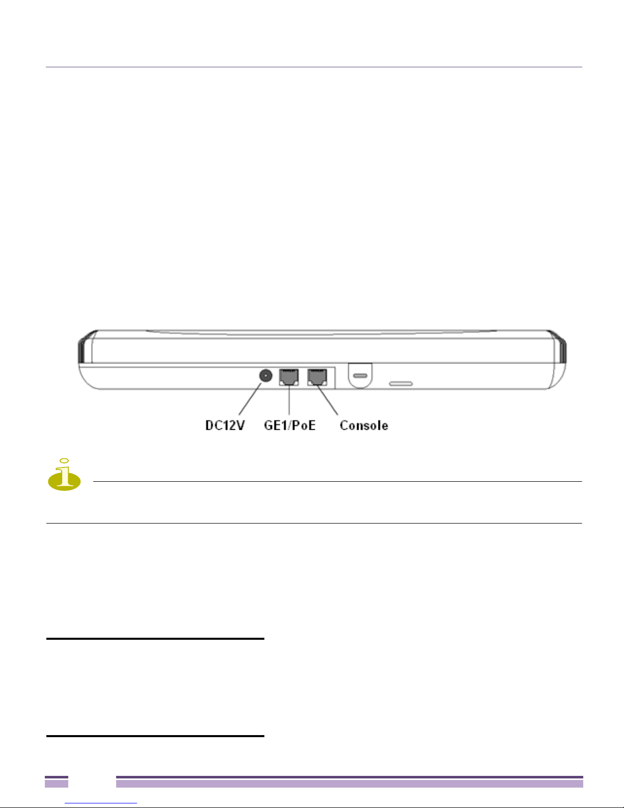
2 RJ-45 connectors, one for 10/100/1000 Ethernet and another for the serial/console
connector
●
LED indicators
●
Slots for wall mounting
●
Clips for mounting on a suspended ceiling T-bar (internal antenna model only) with
separately orderable accessories
●
Lock port for Kensington® style Security Lock
The Altitude 4522 Access Point has one RJ-45 connector supporting an 10/100/1000
Ethernet port and accepts 802.3af-compliant power from an external source. The following
illustration is of an integrated antenna model.
NOTE
When operating in a Gigabit Ethernet environment, CAT-5e or CAT-6 cable is recommended
for Gigabit operation.
The Altitude 4522 Access Point comes with dual radios supporting 802.11abgn. The Access
Point contains runtime firmware which enables the unit to boot after a power up. The
runtime firmware on the Access Point and the firmware downloaded from the connected
controller can be updated by using the Ethernet interface. The console port settings are
shown in the following table:
Bit Rate (bits/sec) 115000
Data Bits 8
Parity None
Stop Bits 1
Flow Control None
Altitude™ 4522 Series Access Point Installation Guide
9

Hardware Installation
2
CHAPTER
Installation Instructions
The Altitude 4522 Access Point mounts either on a wall (with customer supplied M4 x 25
pan head screws and wall anchor - or equivalent) or on a suspended ceiling T-bar. If you
are deploying an external antenna model, the Altitude 4522 Access Point on a suspended
ceiling T-bar, the Access Point mounting kit (Part No. KT-135628-01) is required. The
Altitude 4522 Access Point is not designed for mounting on a desk.
To prepare for the installation:
1 Match the model number on the purchase order with the model numbers in the packing
list and on the case of the Access Point.
SKU Part Number Description
4522i-US 15993 Dual 802.11n radio Altitude 4522 Access Point. Plastic enclosure with
internal antennas. For use in the US deployments only.
4522i-ROW 15994 Dual 802.11n radio Altitude 4522 Access Point. Plastic enclosure with
internal antennas. For use in non-US countries only.
4522i-EU 15815 Dual 802.11n radio Altitude 4522 Access Point. Plastic enclosure with
internal antennas. For deployment in European regulatory domain
only.
4522e-US 15995 Dual 802.11n radio Altitude 4522 Access Point. Metal enclosure with
external antenna connectors. For use in US deployments only.
4522e-ROW 15996 Dual 802.11n radio Altitude 4522 Access Point. Metal enclosure with
external antenna connectors. For use in non-US countries only.
4522e-EU 15816 Dual 802.11n radio Altitude 4522 Access Point. Metal enclosure with
external antenna connectors. For deployment in European regulatory
domain only.
Altitude™ 4522 Series Access Point Installation Guide
10

Precautions
NOTE
In the above part numbers,
is for use in the European Union regulatory domain. “US” defines the model as only legally
deployable in the United States.
a
country code of “ROW” represents a world wide model, “EU”
2 Verify that the contents of the box include the intended Altitude 4522 Access Point, and
the included hardware matches the package contents (see“Package Contents” on page 8).
3 Review site survey and network analysis reports to determine the location and mounting
position for the Altitude 4522 Access Point.
4 Connect a CAT-5 or better Ethernet cable to a compatible 802.3af power source and run
the cable to the installation site. Ensure that there is sufficient slack on the cable to
perform the installation steps.
NOTE
When operating in a Gigabit Ethernet environment, CAT-5e or CAT-6 cable is recommended
for Gigabit operation.
Precautions
Before installing an Altitude 4522 Access Point, verify the following:
●
You are using the correctly rated DC power supply for the Altitude 4522 Access Point
(Part No. PWRS-14000-148R)
●
Extreme Networks recommends that you do not install the Altitude 4522 Access Point in
wet or dusty areas.
●
Verify that the environment has a continuous temperature range between 0° C to 40° C.
Access Point Placement
For optimal performance, install the Access Point away from transformers, heavy-duty
motors, fluorescent lights, microwave ovens, refrigerators, or other industrial equipment.
Altitude™ 4522 Series Access Point Installation Guide
11

Integrated Antenna Model Wall Mount Instructions
Signal loss can occur when metal, concrete, walls, or floors block transmission. Install the
Access Point in an open area or add Access Points as needed to improve coverage.
Antenna coverage is analogous to lighting. Users might find an area lit from far away to be
not bright enough. An area lit sharply might minimize coverage and create dark areas.
Uniform antenna placement in an area (like even placement of a light bulb) provides even,
efficient coverage.
Place the Access Point using the following guidelines:
●
Install the Access Point at an ideal height of 10 feet from the ground.
●
Orient the Access Point antennas vertically for best reception (applies to external
antenna models only).
To maximize the Access Point’s radio coverage area, Extreme Networks recommends
conducting a site survey to define and document radio interference obstacles before
installing the Access Point.
Integrated Antenna Model Wall Mount
Instructions
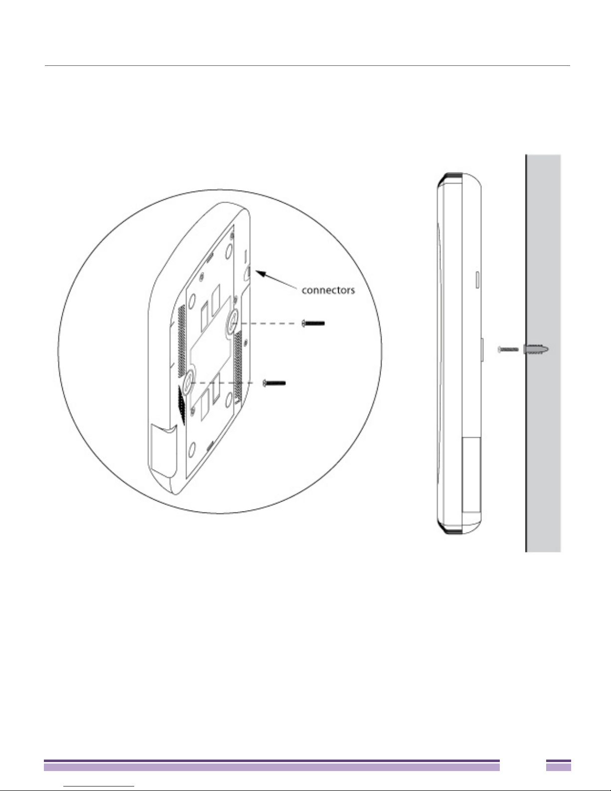
Wall mounting requires hanging the Altitude 4522 Access Point along its width or length
using the two slots on the bottom of the unit. The Altitude 4522 Access Point can be
mounted on to any plaster, wood, or cement wall surface using customer supplied screw
hardware (M3.5 x 0.6 x 20 mm- or equivalent).
Wall Mount Hardware
●
Two wide-shoulder Phillips pan head self-tapping screws (customer supplied)
●
Two wall anchors (custome r s up pl ie d)
●
Security cable (optional)
NOTE
The following screws are recommended: (ANSI Standard) #6-18 X 0.875in. Type A or AB
Self-Tapping Screw, or (ANSI Standard Metric) M3.5 X 0.6 X 20mm Type D Self-Tapping Screw.
Altitude™ 4522 Series Access Point Installation Guide
12
Wall Mount Procedure
Wall Mount Procedure
Altitude™ 4522 Series Access Point Installation Guide
13
Wall Mount Procedure
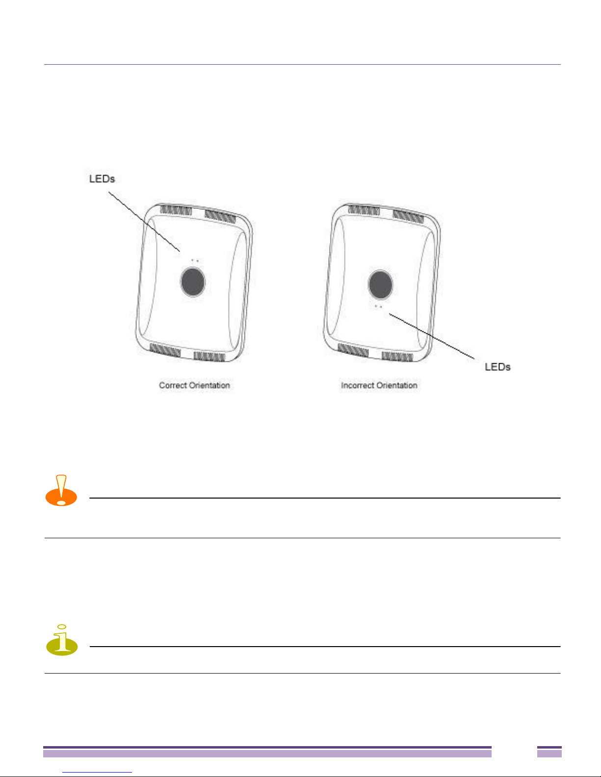
1 Orient the case on the wall by its width or length.
CAUTION
To ensure proper operation of an Altitude 4522 Access Point, ensure that it is mounted in the
correct orientation as shown above.
2 Mark two points (for drill holes) 4.08 inches (103.7 mm) apart on a horizontal line.
3 At each point, drill a hole in the wall, insert an anchor, screw into the anchor the wall
mounting screw and stop when there is 1mm between the screw head and the wall.
NOTE
When pre-drilling a hole, the recommended hole size is 2.8mm (0.11in.).
Altitude™ 4522 Series Access Point Installation Guide
14

Wall Mount Procedure
4 If required, install and attach a Kensington security cable (customer supplied) to the
unit’s lock port.
5 Attach an Ethernet cable from the Access Point to a controller with an 802.3af-compatible
power source or use the PWRS-14000-148R power supply to supply power to the
Altitude 4522 Access Point (once fully cabled).
6 Place the middle of each of the case’s mount slots over the screw heads.
7 Slide the case down along the mounting surface to hang the mount slots on the screw
heads.
8 Verify that the unit has power by observing that the LEDs are lit or flashing.
CAUTION
If you are not using a 802.3af capable controller to power the Altitude 4522 Access Point,
ensure that only the Altitude 4522 Access Point’s designated power supply (PWRS-14000-148R) is
used. Using an incorrectly rated power supply could damage the unit and void the product warranty.
Do not actually connect to the power source until the cabling portion of the installation is complete.
Altitude™ 4522 Series Access Point Installation Guide
15
Integrated Antenna Model Suspended Ceiling T-Bar Mount
Integrated Antenna Model Suspended Ceiling
T- B a r M o u n t
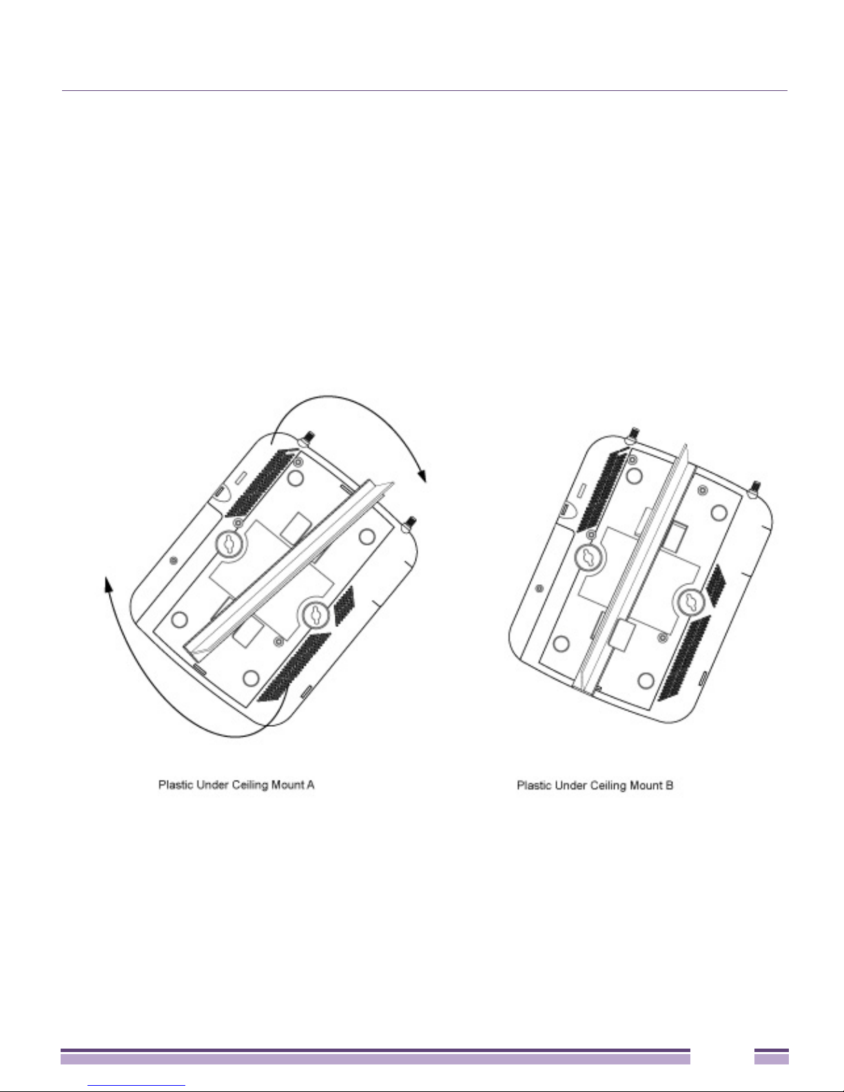
Ceiling mount requires holding the Altitude 4522 Access Point up against a T-bar of a
suspended ceiling grid and twisting the case onto the T-bar.
Suspended Ceiling T-Bar Mount Procedure
1 If required, install and attach a Kensington security cable (customer supplied) to the
unit’s lock port.
2 Attach an Ethernet cable from the Access Point to a controller with an 802.3af compatible
power source or use the PWRS-14000-148R power supply to supply power to the
Altitude 4522 Access Point (once fully cabled).
3 Align the bottom of the T-bar with the back of the case.
Altitude™ 4522 Series Access Point Installation Guide
16

External Antenna Model Wall Mount Instructions
4 Orient the case by its length, and the length of the T-bar.
5 Rotate the case 45 degrees clockwise, or about 10 o’clock.
6 Push the back of the case onto the bottom of the T-bar.
7 Rotate the case 45 degrees counter-clockwise. The clips click as they fasten to the T-bar.
8 Verify that the unit has power by observing the LEDs.
CAUTION
If you are not using a 802.3af capable controller to power the Altitude 4522 Access Point,
ensure that only the Altitude 4522 Access Point’s designated power supply (PWRS-14000-148R) is
used. Using an incorrectly rated power supply could damage the unit and void the product warranty.
Do not actually connect to the power source until the cabling portion of the installation is complete.
External Antenna Model Wall Mount
Instructions
A wall mount deployment requires hanging the Altitude 4522 Access Point along its width
or length using the pair of slots on the bottom of the unit. The Altitude 4522 Access Point
can be mounted on to any plaster, wood, or cement wall surface using the provided wall
anchors.
Wall Mount Hardware
●
Two customer provided wide-shoulder Phillips pan head self-tapping screws
(M3.5 x 0.6 x 20 mm)
●
Two wall anchors (customer supplied)
●
Security cable (optional)
NOTE
The following screws are recommended: (ANSI Standard) #6-18 X 0.875in. Type A or AB
Self-Tapping Screw, or (ANSI Standard Metric) M3.5 X 0.6 X 20mm Type D Self-Tapping Screw.
Altitude™ 4522 Series Access Point Installation Guide
17
External Antenna Model Wall Mount Instructions
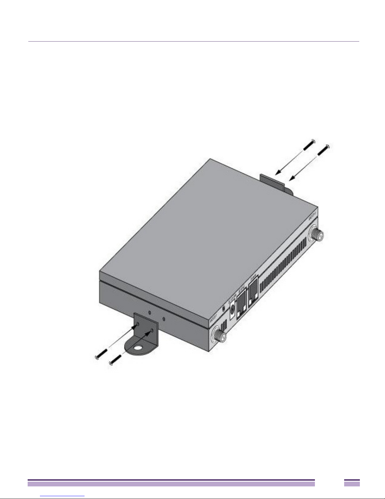
Wall Mount Procedure - New Installation
This section describes a new Altitude 4522 Access Point installation with no previous
Access Point existing on the intended wall surface.
1 Attach the two provided mounting ears (using four ear mounting screws) to the two
narrow ens of the Altitude 4522 Access Point. Align the ears using the built in ear
alignment pin on the Access Point housing. Torque the screws to 6 lb-in.
2 Place the Access Point against the wall, ensuring that the Access Point’s Extreme
Networks logo is oriented upward.
3 Mark the screw hole locations on a vertical axis using the ear’s mounting holes.
4 At each point, drill a hole in the wall and insert the anchor.
Altitude™ 4522 Series Access Point Installation Guide
18

External Antenna Model Wall Mount Instructions
NOTE
When pre-drilling a hole, the recommended hole size is 2.8mm (0.11in.).
5 Place the Access Point on the anchor. Insert screws through the Access Point’s mounting
ears and into the anchor.
6 If required, install and attach a Kensington security cable (customer supplied) to the
unit’s lock port.
7 Attach an Ethernet cable from the Access Point to a controller with an 802.3af-compatible
power source or use the PWRS-14000-148R power supply to supply power to the
Altitude 4522 Access Point (once fully cabled).
8 Attach appropriate antennas to the connectors.
9 Attach an Ethernet cable from the Access Point to a controller with an 802.3af compatible
power source.
10 Verify that the Access Point is receiving power by observing that the LEDs are lit or
flashing.
CAUTION
If you are not using a 802.3af capable controller to power the Altitude 4522 Access Point,
ensure that only the Altitude 4522 Access Point’s designated power supply (PWRS-14000-148R) is
used. Using an incorrectly rated power supply could damage the unit and void the product warranty.
Do not actually connect to the power source until the cabling portion of the installation is complete.
Wall Mount Procedure - Existing Access Point
Replacement
An external antenna Altitude 4600 Series Access Point, installed on a wall (plenum
installation), can be replaced by an Altitude 4522 Access Point. Simply remove the legacy
Access Point from its mounting screws, leave the mounting hardware in place and install
the new external antenna Altitude 4522 Access Point directly on to the existing mounting
hardware. The cabling procedure for such a replacement is the same as described in the
previous section.
Altitude™ 4522 Series Access Point Installation Guide
19

External Antenna Model Suspended Ceiling T-Bar Mount
External Antenna Model Suspended Ceiling TBar Mount
Ceiling mount requires holding the Altitude 4522 Access Point up against a T-bar of a
suspended ceiling grid and twisting the case onto the T-bar. If you are deploying an
external antenna model Altitude 4522 Access Point on a ceiling T-Bar, the Access Point
mounting kit (Part No. KT-135628-01) or ceiling mount hardware (SCT-2) is required.
Suspended Ceiling T-Bar Mount Procedure - Using
Mounting Kit
The following installation uses the Access Point mounting kit (Part No. KT-135628-01) to
deploy the Access Point on a ceiling T-Bar.
1 If required, install and attach a Kensington security cable (customer provided) to the
unit’s lock port.
2 Using only the mounting bracket from the mounting kit, rotate and click the mounting
bracket into the mounting slots on the Altitude 4522 Access Point.
3 Attach an Ethernet cable from the Access Point to a controller with an 802.3af compatible
power source or use the PWRS-14000-148R power supply to supply power to the
Altitude 4522 Access Point (once fully cabled).
4 With the ceiling tile raised, slip the T-Bar bracket on to the exposed T-Bar flange.
5 Lower the ceiling tile and verify the stability of the T-Bar mounting bracket connection.
There will be no stability in this assembly until the ceiling tile is lowered on to the T-Bar
to secure the mounting hardware.
6 Verify that the unit has power by observing the LEDs.
CAUTION
If you are not using a 802.3af capable controller to power the Altitude 4522 Access Point,
ensure that only the Altitude 4522 Access Point’s designated power supply (PWRS-14000-148R) is
used. Using an incorrectly rated power supply could damage the unit and void the product warranty.
Do not actually connect to the power source until the cabling portion of the installation is complete.
Altitude™ 4522 Series Access Point Installation Guide
20
External Antenna Model Suspended Ceiling T-Bar Mount
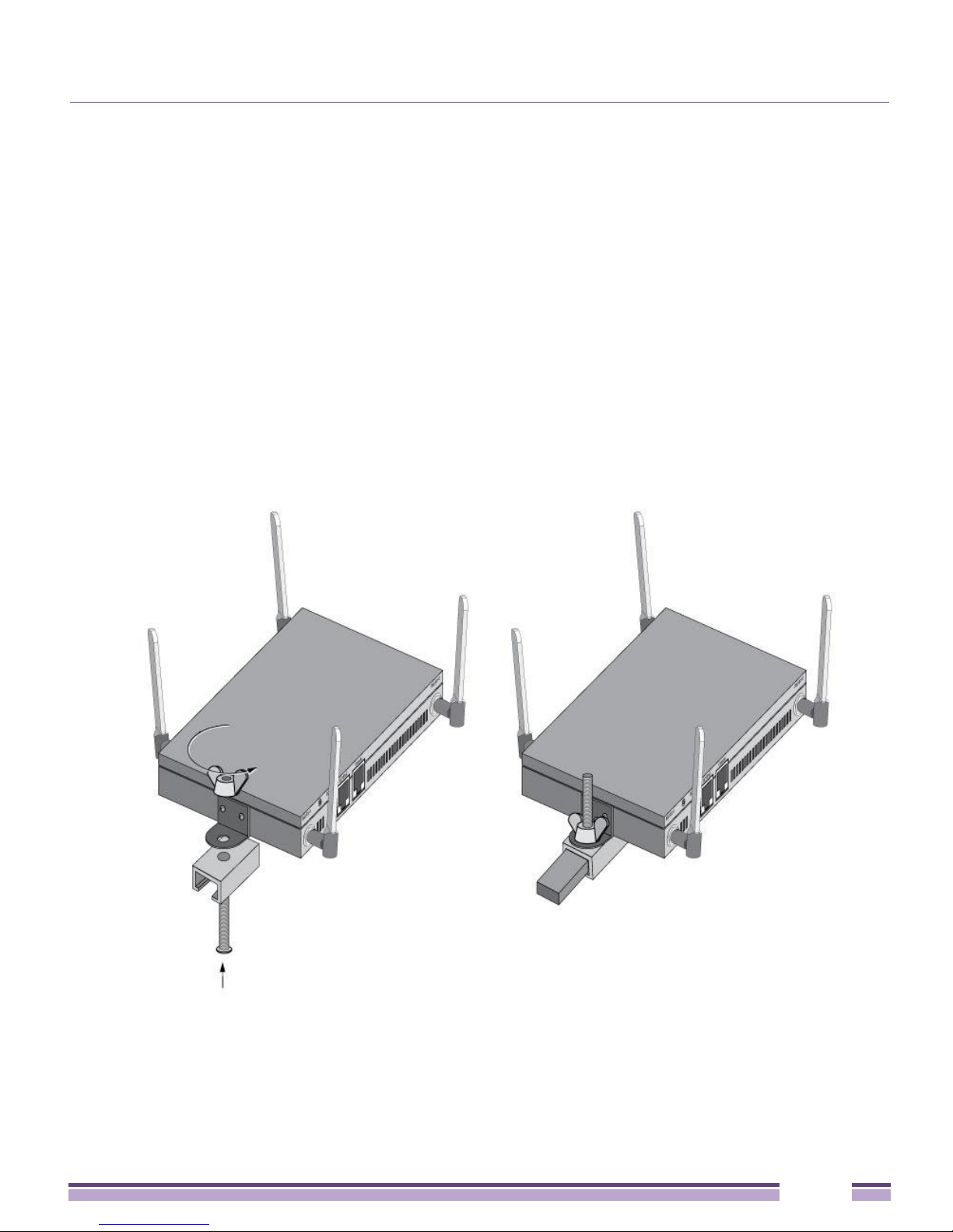
Suspended Ceiling T-Bar Mount Procedure - Using
Ceiling Mount Hardware
The following installation uses the Access Point ceiling mounting kit (Part No. SCT-2) to
deploy the Access Point on a ceiling T-Bar.
1 If required, install and attach a Kensington security cable (customer provided) to the
unit’s lock port.
2 Remove nut from the SCT-2 kit and place assembly and screw through Access Point
mounting ear.
3 Place the clips from the SCT-2 ceiling mount kit over ceiling T-Bar.
4 Tighten clips using provided nuts.
Altitude™ 4522 Series Access Point Installation Guide
21
 Loading...