

Extreme Networks Altitude 4521 Series Installation Manual

Altitude™ 4521 Series Access Point
Installation Guide
Extreme Networks, Inc.
3585 Monroe Street
Santa Clara, California 95051
(888) 257-3000
(408) 579-2800
http://www.extremenetworks.com
Published: October 2012
Part number: 120790-00 Rev 02

AccessAdapt, Alpine, Altitude, BlackDiamond, EPICenter, ExtremeWorks Essentials, Ethernet
Everywhere, Extreme Enabled, Extreme Ethernet Everywhere, Extreme Networks, Extreme Standby
Router Protocol, Extreme Turbodrive, Extreme Velocity, ExtremeWare, ExtremeWorks, ExtremeXOS, Go
Purple Extreme Solution, ExtremeXOS ScreenPlay, ReachNXT, Sentriant, ServiceWatch, Summit,
SummitStack, Triumph, Unified Access Architecture, Unified Access RF Manager, UniStack, the
Extreme Networks logo, the Alpine logo, the BlackDiamond logo, the Extreme Turbodrive logo, the
Summit logos, and the Powered by ExtremeXOS logo are trademarks or registered trademarks of
Extreme Networks, Inc. or its subsidiaries in the United States and/or other countries.
sFlow is a registered trademark of InMon Corporation.
Specifications are subject to change without notice.
All other registered trademarks, trademarks, and service marks are property of their respective
owners.
© 2012 Extreme Networks, Inc. All Rights Reserved.
2
Altitude™ 4521 Series Access Point Installation Guide

Table of Contents
Chapter 1: Introduction....................................................................................................5
Document Conventions...............................................................................................................6
Warnings..................................................................................................................................... 7
Site Preparation.......................................................................................................................... 7
Package Contents ......................................................................................................................7
Features...................................................................................................................................... 8
Chapter 2: Hardware Installation ....................................................................................9
Installation Instructions ............................................................................................................... 9
Precautions............................................................................................................................... 10
Access Point Placement ........................................................................................................... 10
Antenna Options................................................................................................................ 11
Power Injector System....................................................................................................... 12
Wall Mount Installation.............................................................................................................. 14
Suspended Ceiling T-Bar Installation........................................................................................16
Above the Ceiling (Plenum) Installation ................................................................................... 18
LED Indicator ............................................................................................................................ 20
Chapter 3: Defining a Basic Configuration ..................................................................23
Using the Initial Setup Wizard...................................................................................................23
Chapter 4: Specifications ..............................................................................................47
Electrical Characteristics........................................................................................................... 47
Physical Characteristics............................................................................................................ 47
Radio Characteristics................................................................................................................ 48
Chapter 5: Regulatory Information ...............................................................................49
Regulatory Overview................................................................................................................. 49
Wireless Device Country Approvals.......................................................................................... 49
Country Selection – Note for AP & Wireless Controller..................................................... 50
Frequency of Operation – FCC and IC.............................................................................. 50
Health and Safety Recommendations ...................................................................................... 51
Warnings for the use of Wireless Devices......................................................................... 51
Potentially Hazardous Atmospheres – Fixed Installations................................................. 51
Altitude™ 4521 Series Access Point Installation Guide
3

Table of Contents
Safety in Hospitals.............................................................................................................51
RF Exposure Guidelines...........................................................................................................52
Safety Information ............................................................................................................. 52
International.............................................................................................................................. 52
EU............................................................................................................................................. 52
US and Canada ........................................................................................................................ 53
Power Supply............................................................................................................................53
Radio Frequency Interference Requirements – FCC................................................................ 54
Radio Frequency Interference Requirements – Canada ......................................................... 54
Radio Transmitters ............................................................................................................ 55
CE Marking and European Economic Area (EEA).................................................................... 55
Statement of Compliance.......................................................................................................... 55
Waste Electrical and Electronic Equipment (WEEE) ................................................................ 56
Japan (VCCI) - Voluntary Control Council for Interference Class B ITE .................................. 58
Korea Warning Statement for Class B ITE ............................................................................... 58
Other Countries ........................................................................................................................59
Australia............................................................................................................................. 59
Brazil.................................................................................................................................. 59
Chile ..................................................................................................................................59
Mexico ............................................................................................................................... 59
Taiwan ............................................................................................................................... 60
Korea ................................................................................................................................. 61
Chapter 6: Customer Support .......................................................................................62
Registration............................................................................................................................... 62
Documentation.......................................................................................................................... 63
4
Altitude™ 4521 Series Access Point Installation Guide

Introduction
1
CHAPTER
Altitude™ 4521 Series Access Points are components of Extreme Networks® Wireless
Mobility System. An Altitude 4521 Series Access Point links wireless 802.11a/b/g/n devices
to the Summit
with a cost-effective alternative to standard Access Points. The Altitude 4521 Series Access
Point is an enterprise class 802.11n Access Point, installed in minutes anywhere a CAT-5e
(or better) cable is located. An Altitude 4521 Series Access Point utilizes a setup wizard to
define its operational mode as either a Dependent mode AP, Standalone AP or Virtual
Controller AP.
An Altitude 4521 Series Access Points ship with a single dual-band radio supporting the
802.11a/b/g/n radio bands. For more information on available SKUs, refer to the following:
®
WM3000 Series Controller, enabling the growth of your wireless network
Part
SKU
AP4521i-US 15789 Altitude AP4521i single-radio Independent indoor Access Point for US
AP4521i-ROW 15790 Altitude AP4521i single-radio Independent indoor Access Point for the
AP4521i-EU 15809 Altitude AP4521i single-radio Independent indoor Access Point for the
AP4521e-US 15791 Altitude AP4521e single-radio Independent indoor Access Point for
Altitude™ 4521 Series Access Point Installation Guide
Number Description
regulatory domain, 802.11a/b/g/n, 2x2 MIMO, Includes internal
omnidirectional antennas, Powered by 802.3af/at PoE or by use of a
PoE injector.
Rest of World regulatory domain, 802.11a/b/g/n, 2x2 MIMO, Includes
internal omni-directional antennas, Powered by 802.3af/at PoE or by
use of a PoE injector.
European Union regulatory domain, 802.11a/b/g/n, 2x2 MIMO,
Includes internal omni-directional antennas, Powered by 802.3af/at
PoE or by use of a PoE injector.
US regulatory domain, 802.11a/b/g/n, 2x2 MIMO. External antennas
not included-must order separately up to 2 paddle antennas. Powered
by 802.3af/at PoE or by use of a PoE injector.
5

Chapter 1: Introduction
AP4521e-ROW 15793 Altitude AP4521e single-radio Independent indoor Access Point for
the Rest of World regulatory domain, 802.11a/b/g/n, 2x2 MIMO.
External antennas not included-must order separately up to 2 paddle
antennas. Powered by 802.3af/at PoE or by use of a PoE injector.
AP4521e-EU 15810 Altitude AP4521e single-radio Independent indoor Access Point for
the European Union regulatory domain, 802.11a/b/g/n, 2x2 MIMO.
External antennas not included-must order separately up to 2 paddle
antennas. Powered by 802.3af/at PoE or by use of a PoE injector.
The Altitude 4521 Series Access Point is approved under MODEL: NCAP-500.
Extreme Networks recommends the Access Point receive power and transfer data through
the same CAT-5e (or better) Ethernet cable using an Extreme Networks approved Power
Injector. The Power Injector (Part No. AP-PSBIAS-2P2-AFR) is an 802.3af PoE injector. For
information, see “Power Injector System” on page 12.
A separate power supply (Part No. PWRS-147376-01R) is available if you do not wish to use
a Power Injector. This standard power supply just supplies power to the Access Point’s
power connector and does not converge power and Ethernet within a single cable
connection.
Document Conventions
The following graphical alerts are used in this guide to indicate notable situations:
NOTE
Tips, hints, or special requirements that you should take note of.
CAUTION
Care is required. Disregarding a caution can result in data loss or equipment malfunction.
WARNING!
Indicates a condition or procedure that could result in personal injury or equipment damage.
6
Altitude™ 4521 Series Access Point Installation Guide

Warnings
Warnings
●
Read all installation instructions and site survey reports, and verify correct equipment
installation before connecting the Access Point.
●
Verify any device connected to this unit is properly wired and grounded.
●
Verify there is adequate ventilation around the device, and ambient temperatures meet
equipment operation specifications.
Site Preparation
●
Consult your site survey and network analysis to determine specific equipment
placement, power drops etc.
●
Assign installation responsibility to the appropriate personnel.
●
Identify and document where all installed components are located.
●
Ensure adequate, dust-free ventilation to all installed equipment.
●
Prepare Ethernet port connections.
●
Verify cabling is within the maximum 100 meter allowable length.
Package Contents
The Access Point ships with the following:
●
One Altitude 4521 Series Access Point
●
Installation Guide (This Guide)
●
Rubber Wall Mount Spacers (4)
●
LED light pipe and badge
●
Wall mount screw and anchor kit
Altitude™ 4521 Series Access Point Installation Guide
7

Chapter 1: Introduction
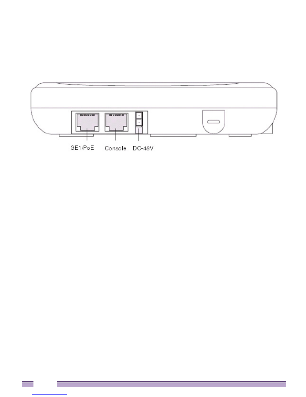
Features
●
One RJ-45 console connector
●
One RJ-45 Ethernet connector
●
LED Indicators
●
Safety wire tie point
●
Wal l mount s lots
●
Clips for suspended T-Bar mounting
●
DC power connector
An Altitude 4521 Series Access Point has one RJ-45 connector supporting an 10/100/1000
Ethernet port connection and requires 802.3af compliant power from an external source.
The Access Point contains runtime firmware which enables the unit to boot after either a
power up or a watchdog reset. The runtime firmware on the Access Point can be updated
via the Ethernet interface.
8
Altitude™ 4521 Series Access Point Installation Guide

Hardware Installation
2
CHAPTER
Installation Instructions
An Altitude 4521 Series Access Point can attach to a wall, mount under a suspended T-Bar
or mount above a ceiling. Selecting a mounting option based on the physical environment
of the coverage area. Do not mount the Access Point in a location that has not been
approved in a site survey.
To prepare for an installation, perform the following:
1 Verify the contents of the box includes the intended Access Point and accessory
hardware.
2 Review site survey and network analysis reports to determine the location and mounting
position for the Access Point.
3 Connect a CAT-5e or better Ethernet cable to a PoE compatible device and run the cable
to the installation site. Ensure there is sufficient cable slack to perform the installation
steps.
Altitude™ 4521 Series Access Point Installation Guide
9
Chapter 2: Hardware Installation
4 Determine whether the Access Point is powered using a Power Injector system,
combining data and power to the Access Point’s GE1/PoE port, or is powered from a
conventional power adapter providing power only to the Access Point’s DC-48V
connector.
Precautions
Before installing an Access Point:
●
Verify the intended deployment location is not prone to moisture or dust.
●
Verify the environment has a continuous temperature range between 0° C to 40° C.
Access Point Placement
For optimal performance, install the Access Point away from transformers, heavy-duty
motors, fluorescent lights, microwave ovens, refrigerators and other industrial equipment.
Signal loss can occur when metal, concrete, walls or floors block transmission. Install the
Access Point in an open area or add Access Points as needed to improve coverage.
Antenna coverage is analogous to lighting. Users might find an area lit from far away to be
not bright enough. An area lit sharply might minimize coverage and create dark areas.
Uniform antenna placement in an area (like even placement of a light bulb) provides even,
efficient coverage.
10
Altitude™ 4521 Series Access Point Installation Guide
Access Point Placement
Place the Access Point using the following guidelines:
●
Install the Access Point at an ideal height of 10 feet from the ground.
●
Orient the Access Point antennas vertically for best reception.
●
Point the Access Point antennas downward if attaching to the ceiling (external antenna
models only).
To maximize the Access Point’s radio coverage area, Extreme Networks recommends
conducting a site survey to define and document radio interference obstacles before
installing the Access Point.
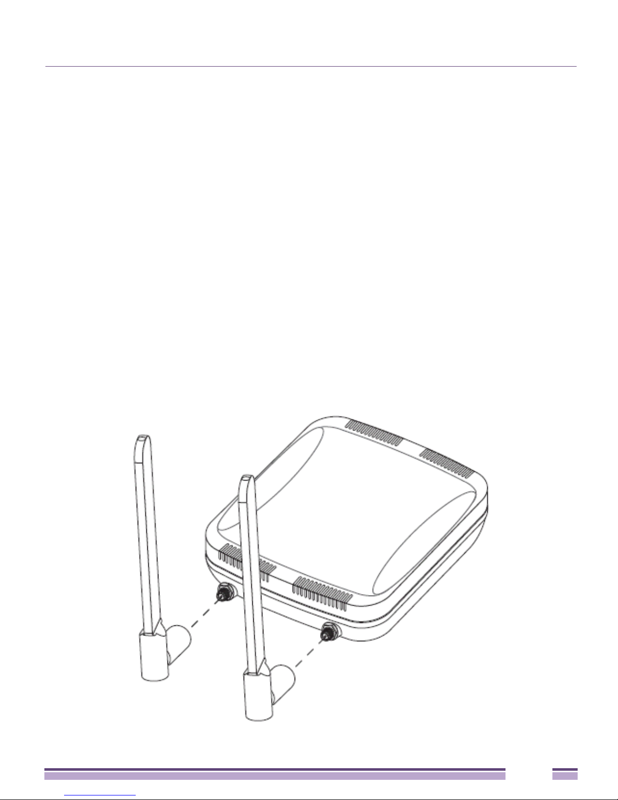
Antenna Options
Extreme Networks supports various antennas for the single radio, dual-band Altitude 4521
Series Access Point. These antennas support the 2.4 GHz band, the 5 GHz band, or both.
Select an antenna best suited to the intended operational environment of your Access Point.
For example, pictured below are two popular dual-band, omni-directional antennas for
typical indoor coverage (ML-2452-APA2-01 for Black and ML-2452-APAG2A1-02 for White).
Altitude™ 4521 Series Access Point Installation Guide
11

Chapter 2: Hardware Installation
For a more exhaustive overview of the antennas supported by the Extreme Networks
Access Point family, refer to the Enterprise Wireless LAN Antenna Specification Guide and
Enterprise Wireless LAN Antenna Specification Guide Addendum documents available from
http://www.extremenetworks.com/go/documentation
.
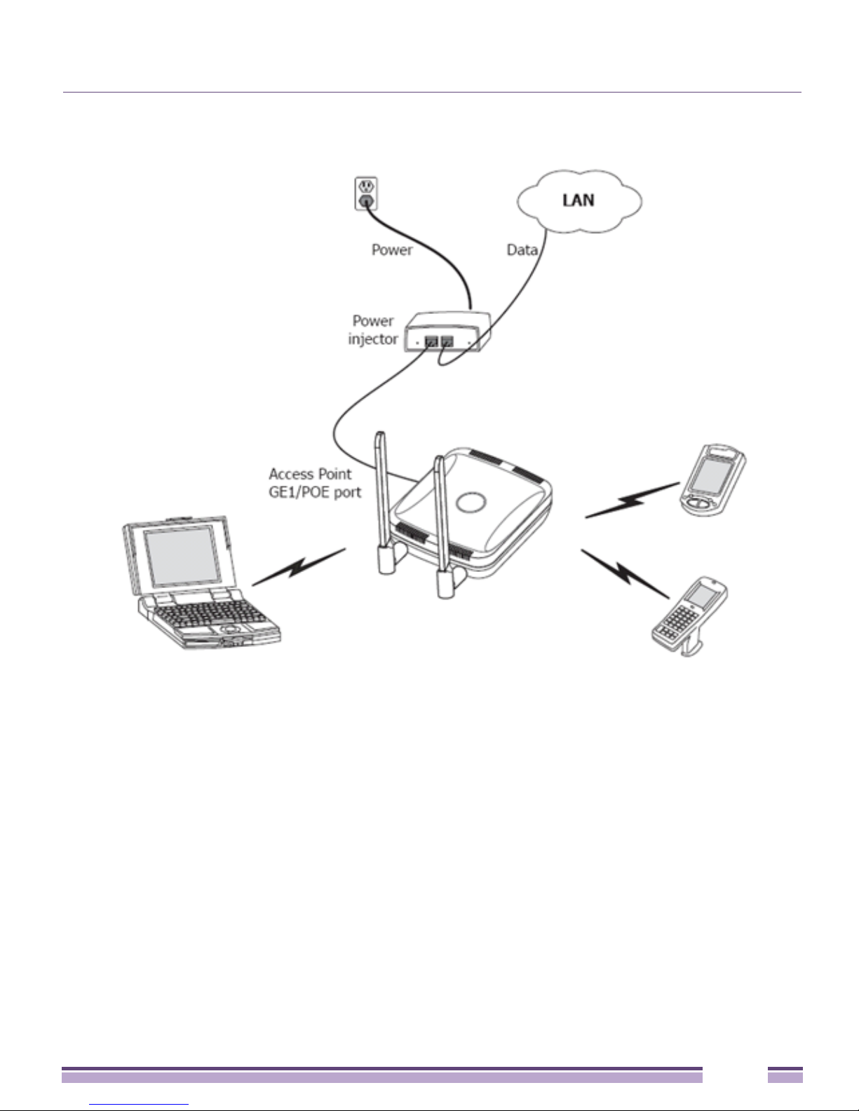
Power Injector System
The Access Point can receive power via an Ethernet cable connected to the GE1/PoE port.
When users purchase a WLAN solution, they often need to place Access Points in obscure
locations. In the past, a dedicated power source was required for each Access Point in
addition to the Ethernet infrastructure. This often required an electrical contractor to install
power drops at each Access Point location. The Power Injector merges power and Ethernet
into one cable, reducing the burden of installation and allowing optimal Access Point
placement in respect to the intended coverage area.
The Power Injector (Part No. AP-PSBIAS-2P2-AFR) is an 802.3af PoE injector. The Access
Point can only use a Power Injector when connecting to the Access Point’s GE1/PoE port.
The Power Injector is separately ordered and not shipped with the Access Point. A separate
Power Injector is required for each Access Point comprising the network.
The Power Injector has no On/Off power switch. The Injector receives power and is ready
for device connection and operation as soon as AC power is applied. Refer to the guide
shipped with the Power Injector for a description of the device’s LEDs. The Power Injector
can be installed free standing, on an even horizontal surface or wall mounted using the
Power Injector’s wall mounting key holes.
12
Altitude™ 4521 Series Access Point Installation Guide
Access Point Placement
The following guidelines should be adhered to before cabling the Power Injector to an
Ethernet source and an Access Point:
●
Do not block or cover airflow to the Power Injector.
●
Keep the Power Injector away from excessive heat, humidity, vibration and dust.
●
The Power Injector isn’t a repeater, and does not amplify the Ethernet signal. For optimal
performance, ensure the Power Injector is placed as close as possible to the Ethernet
switch. This allows the Access Point to be deployed away from power drops.
●
Ensure the cable length from the Ethernet source (host) to the Power Injector and Access
Point does not exceed 100 meters (333 ft).
Altitude™ 4521 Series Access Point Installation Guide
13

Chapter 2: Hardware Installation
CAUTION
To avoid problematic performance and restarts, disable PoE from a wired controller port
connected to an Access Point if mid-span power sourcing equipment (PSE) is used between the two,
regardless of the manufacturer.
CAUTION
Ensure AC power is supplied to the Power Injector using an AC cable with an appropriate
ground connection approved for the country of operation.
NOTE
If not using the Power Injector to power the Access Point, the only other approved power
solution is the standard power supply (Part Number PWRS-147376-01R). The standard power supply
does not converge data and power in one cable, and requires a separate data Ethernet connection in
addition to a power connection. This product is intended to be supplied by a listed power adapter
marked “Class 2” or “L.P.S” (or “Limited Power Source”) and rated from 48Vdc, 0.27A minimum.
Wall Mount Installation
To support wall mount installations, the Access Point is fastened directly to a flat wall
surface. The wall should be of gypsum board, plaster, wood or concrete in composition.
CAUTION
An Access Point should be wall mounted to concrete or plaster-wall-board (dry wall) only. Do
not wall mount the Access Point to combustible surfaces.
To install the Access Point to a wall:
1 Orient the Access Point by either its width or length.
2 Mark the mounting surface at the target screw insertion points.
14
Altitude™ 4521 Series Access Point Installation Guide

Wall Mount Installation
3 At each point, drill a hole in the wall, insert an anchor, screw into the anchor the wall
mounting screw and stop when there is 1mm between the screw head and the wall.
If pre-drilling a hole, the recommended hole size is 2.8mm (0.11in.) if the screws are
going directly into the wall and 6mm (0.23in.) if wall anchors are being used.
4 If required, install and attach a security cable to the Access Point lock port.
5 Attach the antennas to their correct connectors. For information on available antennas,
see “Antenna Options” on page 11.
6 Place the large center opening of each of the mount slots over the screw heads.
7 Slide the Access Point down along the mounting surface to hang the mount slots on the
screw heads
8 Cable the Access Point using an approved line cord and power supply.
For Power Injector installations:
a Connect a RJ-45 CAT5e (or CAT6) Ethernet cable between the network data supply
(host) and the Power Injector Data In connector.
b Connect a RJ-45 CAT5e (or CAT6) Ethernet cable between the Power Injector Data &
Power Out connector and the Access Point GE1/PoE port.
c Ensure the cable length from the Ethernet source (host) to the Power Injector and
Access Point does not exceed 100 meters (333 ft). The Power Injector has no On/Off
power switch. The Power Injector receives power as soon as AC power is applied.
For more information on using the Power Injector, see “Power Injector System” on
page 12.
For power adapter (Part Number PWRS-147376-01R) and line cord installations:
a Connect a RJ-45 CAT5e (or CAT6) Ethernet cable between the network data supply
(host) and the Access Point’s GE1/PoE.
b Verify the power adapter is correctly rated according the country of operation.
c Connect the power supply line cord to the power adapter.
d Attach the power adapter cable to the DC-48V power connector on the Access Point.
e Attach the power supply line cord to a power supply.
CAUTION
Do not connect to the power source until the cabling of the Access Point is complete.
Ensure PoE is not connected to the Access Point’s console connector or risk rendering the console
connector permanently inoperable.
Altitude™ 4521 Series Access Point Installation Guide
15

Chapter 2: Hardware Installation
9 Verify the behavior of the Access Point LEDs. For more information, see “LED Indicator”
on page 20.
10 The Access Point is ready to configure. For information on basic Access Point device
configuration, see “Defining a Basic Configuration” on page 23.
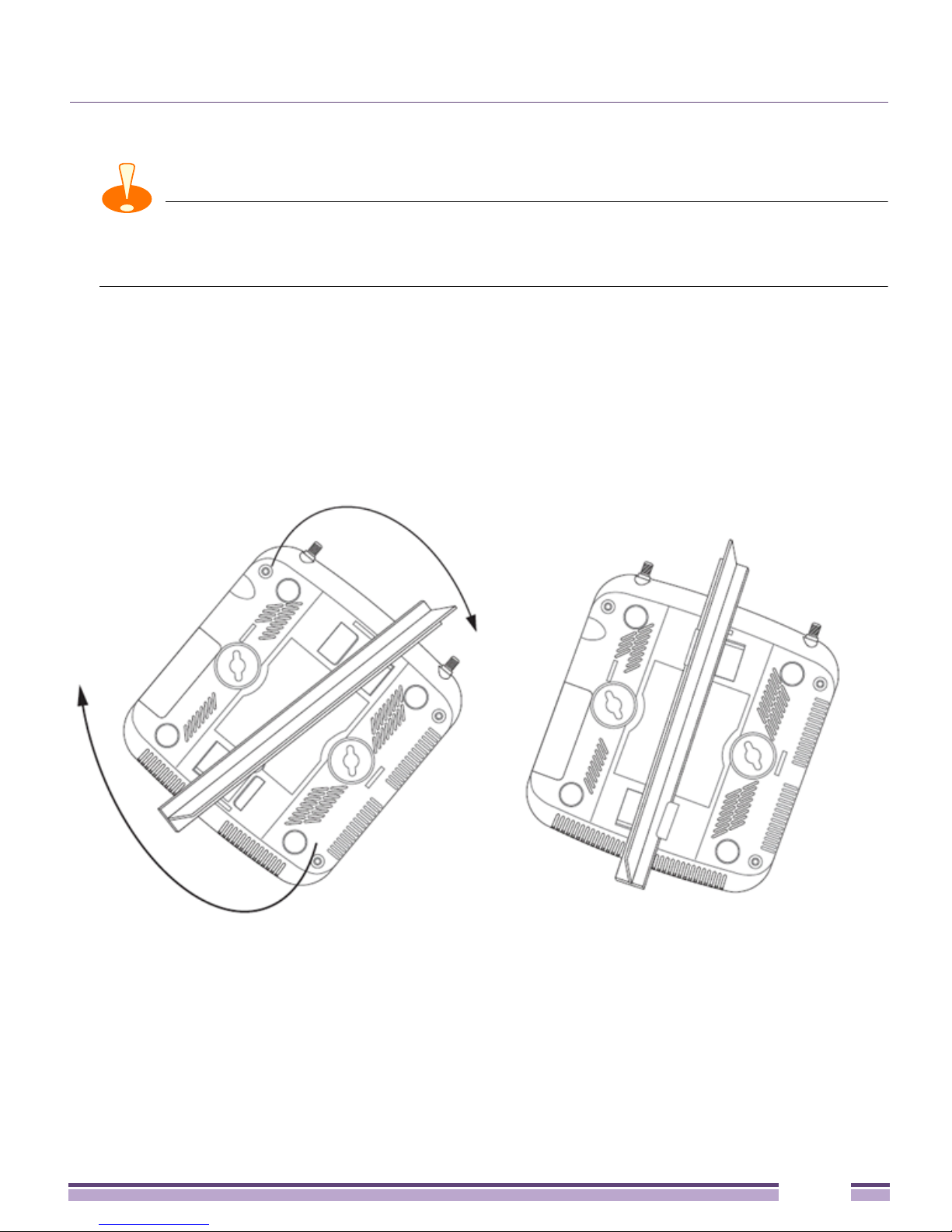
Suspended Ceiling T-Bar Installation
A suspended ceiling mount requires holding the Access Point up against the T-bar of a
suspended ceiling grid and twisting the Access Point chassis onto the T-bar.
To install the Access Point on a ceiling T-bar:
1 If desired, install and attach a security cable to the Access Point lock port.
2 If using an external antenna model, attach the antennas to their correct connectors.
3 For more information on the antenna options available to the Access Point, see “Antenna
Options” on page 11.
4 Cable the Access Point using an approved line cord and power supply.
For Power Injector installations:
a Connect a RJ-45 CAT5e (or CAT6) Ethernet cable between the network data supply
(host) and the Power Injector Data In connector.
b Connect a RJ-45 CAT5e (or CAT6) Ethernet cable between the Power Injector Data &
Power Out connector and the Access Point GE1/PoE port.
c Ensure the cable length from the Ethernet source (host) to the Power Injector and
Access Point does not exceed 100 meters (333 ft). The Power Injector has no On/Off
power switch. The Power Injector receives power as soon as AC power is applied.
For more information on using the Power Injector, see “Power Injector System” on
page 12.
For power adapter (Part Number PWRS-147376-01R) and line cord installations:
a Connect a RJ-45 CAT5e (or CAT6) Ethernet cable between the network data supply
(host) and the Access Point’s GE1/PoE.
b Verify the power adapter is correctly rated according the country of operation.
c Connect the power supply line cord to the power adapter.
d Attach the power adapter cable to the DC-48V power connector on the Access Point.
e Attach the power supply line cord to a power supply.
16
Altitude™ 4521 Series Access Point Installation Guide
Suspended Ceiling T-Bar Installation
CAUTION
Do not connect to the power source until the cabling of the Access Point is complete.
Ensure PoE is not connected to the Access Point’s console connector or risk rendering the console
connector permanently inoperable.
5 Verify the behavior of the Access Point LEDs. For more information, see “LED Indicator”
on page 20.
6 Align the bottom of the ceiling T-bar with the back of the Access Point.
7 Orient the Access Point chassis by its length and the length of the ceiling T-bar.
8 Rotate the Access Point chassis 45 degrees clockwise.
9 Push the back of the Access Point chassis on to the bottom of the ceiling T-bar.
10 Rotate the Access Point chassis 45 degrees counter-clockwise. The clips click as they
fasten to the T-bar.
11 Verify the behavior of the Access Point LEDs. For more information, see “LED Indicator”
on page 20.
12 The Access Point is ready to configure. For information on basic Access Point device
configuration, see “Defining a Basic Configuration” on page 23.
Altitude™ 4521 Series Access Point Installation Guide
17

Chapter 2: Hardware Installation
Above the Ceiling (Plenum) Installation
An above the ceiling installation requires placing the Access Point above a suspended
ceiling and installing the provided light pipe under the ceiling tile for viewing the status
LED of the unit. An above the ceiling deployment enables installations compliant with drop
ceilings, suspended ceilings and industry standard tiles from .625 to .75 inches thick.
NOTE
The Access Point is Plenum rated to UL2043 and NEC1999 to support above the ceiling
installations. To ensure UL compliance and proper Access Point operation within the Air Handling
Plenum, the Access Point must be installed with the bottom surface of the unit in contact with the unfinished surface of the ceiling tile. Placing the product on the ceiling tile will facilitate the positioning of
the light pipe. Placement of the product in the Air Handling Plenum off of, or away from, the unfinished
surface of the ceiling tile is not UL approved and certification of UL2043 compliance would be void in
that case.
CAUTION
Extreme Networks does not recommend mounting the Access Point directly to suspended
ceiling tile with a thickness less than 12.7mm (0.5in.) or a suspended ceiling tile with an unsupported
span greater than 660mm (26in.).
The mounting hardware required to install the Access Point above a ceiling consists of:
●
Light pipe
●
Badge for light pipe
●
Decal for badge
To install the Access Point above a ceiling:
1 If possible, remove the adjacent ceiling tile from its frame and place it aside.
2 If required, install and attach a security cable to the Access Point’s lock port.
3 Mark a point on the finished side of the tile where the light pipe is to be located.
4 Create a light pipe path hole in the target position on the ceiling tile.
5 Use a drill to make a hole in the tile the approximate size of the Access Point LED light
pipe.
18
Altitude™ 4521 Series Access Point Installation Guide

Above the Ceiling (Plenum) Installation
CAUTION
Extreme Networks recommends care be taken not to damage the finished surface of the
ceiling tile when creating the light pipe hole and installing the light pipe.
6 Remove the light pipe’s rubber stopper (from the Access Point) before installing the light
pipe.
7 Connect the light pipe to the bottom of the Access Point. Align the tabs and rotate
approximately 90 degrees. Do not over tighten.
8 Fit the light pipe into hole in the tile from its unfinished side.
9 Place the decal on the back of the badge and slide the badge onto the light pipe from the
finished side of the tile.
10 Attach the antennas to their correct connectors. For information on the antennas
available to the Access Point, see “Antenna Options” on page 11.
11 Align the ceiling tile into its former ceiling space.
12 Cable the Access Point using an approved line cord and power supply.
For Power Injector installations:
a Connect a RJ-45 CAT5e (or CAT6) Ethernet cable between the network data supply
(host) and the Power Injector Data In connector.
b Connect a RJ-45 CAT5e (or CAT6) Ethernet cable between the Power Injector Data &
Power Out connector and the Access Point GE1/PoE port.
c Ensure the cable length from the Ethernet source (host) to the Power Injector and
Access Point does not exceed 100 meters (333 ft). The Power Injector has no On/Off
power switch. The Power Injector receives power as soon as AC power is applied.
For more information on using the Power Injector, see “Power Injector System” on
page 12.
For power adapter (Part Number PWRS-147376-01R) and line cord installations:
a Connect a RJ-45 CAT5e (or CAT6) Ethernet cable between the network data supply
(host) and the Access Point’s GE1/PoE.
b Verify the power adapter is correctly rated according the country of operation.
c Connect the power supply line cord to the power adapter.
d Attach the power adapter cable to the DC-48V power connector on the Access Point.
e Attach the power supply line cord to a power supply.
Altitude™ 4521 Series Access Point Installation Guide
19
Chapter 2: Hardware Installation
CAUTION
Do not connect to the power source until the cabling of the Access Point is complete.
Ensure PoE is not connected to the Access Point’s console connector or risk rendering the console
connector permanently inoperable.
13 Verify the behavior of the Access Point LED light pipe. For more information, see “LED
Indicator” on page 20.
14 Place the ceiling tile back in its frame and verify it is secure.
15 The Access Point is ready to configure. For information on basic Access Point device
configuration, see “Using the Initial Setup Wizard” on page 23.
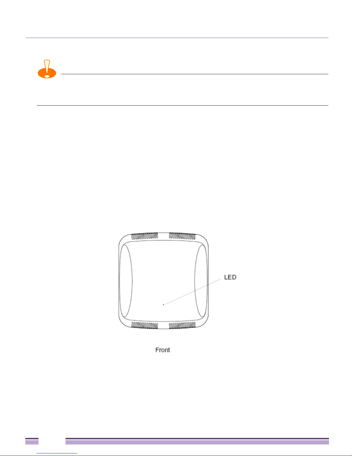
LED Indicator
An Altitude 4521 Series Access Point has a single LED activity indicator on the front of the
unit.
20
Altitude™ 4521 Series Access Point Installation Guide
 Loading...