

Extreme Networks Altitude 4000 Series Reference Manual

Altitude
TM
4000 Series Access Point System
Reference Guide
Software Version 5.2
Extreme Networks, Inc.
3585 Monroe Street
Santa Clara, California 95051
(888) 257-3000
(408) 579-2800
http://www.extremenetworks.com
Published: November 2011
Part number: 120735-00 Rev 1

AccessAdapt, Alpine, Altitude, BlackDiamond, EPICenter, ExtremeWorks Essentials, Ethernet Everywhere, Extreme
Enabled, Extreme Ethernet Everywhere, Extreme Networks, Extreme Standby Router Protocol, Extreme Turbodrive,
Extreme Velocity, ExtremeWare, ExtremeWorks, ExtremeXOS, Go Purple Extreme Solution, ExtremeXOS ScreenPlay,
ReachNXT, Sentriant, ServiceWatch, Summit, SummitStack, Triumph, Unified Access Architecture, Unified Access
RF Manager, UniStack, the Extreme Networks logo, the Alpine logo, the BlackDiamond logo, the Extreme
Turbodrive logo, the Summit logos, and the Powered by ExtremeXOS logo are trademarks or registered trademarks
of Extreme Networks, Inc. or its subsidiaries in the United States and/or other countries.
sFlow is a registered trademark of InMon Corporation.
Specifications are subject to change without notice.
All other registered trademarks, trademarks, and service marks are property of their respective owners.
© 2011 Extreme Networks, Inc. All Rights Reserved.
2
AltitudeTM 4000 Series Access Point System Reference Guide

Table of Contents
Chapter 1: About this Guide ......................................................................................................................9
Documentation Set...................................................................................................................................................9
Document Conventions ............................................................................................................................................9
Notational Conventions ..........................................................................................................................................10
Chapter 2: Overview .................................................................................................................................11
About the Extreme Networks Access Point Software.............................................................................................12
Chapter 3: Web UI Overview.................................................................................................................... 15
Accessing the Web UI ............................................................................................................................................15
Browser and System Requirements................................................................................................................15
Connecting to the Web UI Locally...................................................................................................................16
Glossary of Icons Used ..........................................................................................................................................17
Global Icons ....................................................................................................................................................17
Dialog Box Icons .............................................................................................................................................18
Table Icons......................................................................................................................................................18
Status Icons ....................................................................................................................................................19
Configurable Objects.......................................................................................................................................19
Configuration Objects......................................................................................................................................22
Configuration Operation Icons ........................................................................................................................22
Access Type Icons ..........................................................................................................................................23
Administrative Role Icons................................................................................................................................23
Device Icons....................................................................................................................................................24
Chapter 4: Quick Start.............................................................................................................................. 25
Using the Initial Setup Wizard ................................................................................................................................25
Chapter 5: Dashboard ..............................................................................................................................45
Dashboard..............................................................................................................................................................45
Dashboard Conventions..................................................................................................................................46
Health.......................................................................................................................................................47
Inventory ..................................................................................................................................................51
Network View .........................................................................................................................................................54
Network View Display Options ........................................................................................................................55
Device Specific Information.............................................................................................................................56
Chapter 6: Device Configuration............................................................................................................. 59
RF Domain Configuration.......................................................................................................................................59
RF Domain Sensor Configuration...........................................................................................................................61
System Profile Configuration..................................................................................................................................62
General Profile Configuration..........................................................................................................................63
Profile Radio Power ........................................................................................................................................64
Profile Adoption (Auto Provisioning) Configuration .........................................................................................66
Profile Interface Configuration.........................................................................................................................67
Ethernet Port Configuration .....................................................................................................................68
Virtual Interface Configuration .................................................................................................................73
Port Channel Configuration......................................................................................................................76
Access Point Radio Configuration ...........................................................................................................82
AltitudeTM 4000 Series Access Point System Reference Guide
3

Table of Contents
WAN Backhaul Configuration ..................................................................................................................90
WAN Backhaul Deployment Considerations............................................................................................91
Profile Network Configuration .........................................................................................................................92
DNS Configuration ...................................................................................................................................92
ARP..........................................................................................................................................................93
Quality of Service (QoS) ..........................................................................................................................95
Static Routes............................................................................................................................................96
Forwarding Database...............................................................................................................................97
Bridge VLAN ............................................................................................................................................99
Miscellaneous Network Configuration....................................................................................................102
Profile Network Configuration and Deployment Considerations ............................................................103
Profile Security Configuration........................................................................................................................104
Defining Profile Security Settings...........................................................................................................104
Setting the Certificate Revocation List (CRL) Configuration ..................................................................105
Setting the Profile’s NAT Configuration .................................................................................................106
Profile Security Configuration and Deployment Considerations ............................................................113
Profile Services Configuration.......................................................................................................................113
Profile Services Configuration and Deployment Considerations............................................................114
Profile Management Configuration................................................................................................................115
Upgrading Altitude 4532 Firmware from 5.1 to 5.2 ................................................................................120
Profile Management Configuration and Deployment Considerations ....................................................121
Advanced Profile Configuration.....................................................................................................................121
Advanced Profile Client Load Balancing ................................................................................................121
Configuring MINT...................................................................................................................................125
Advanced Profile Miscellaneous Configuration......................................................................................130
Managing Virtual Controllers ................................................................................................................................132
Overriding a Device Configuration........................................................................................................................134
Basic Configuration ..............................................................................................................................................135
Assigning Certificates...........................................................................................................................................137
Certificate Management ................................................................................................................................139
RSA Key Management..................................................................................................................................146
Certificate Creation .......................................................................................................................................150
Generating a Certificate Signing Request.....................................................................................................151
RF Domain Overrides...........................................................................................................................................153
Profile Overrides...................................................................................................................................................155
Radio Power Overrides ........................................................................................................................................157
Adoption Overrides...............................................................................................................................................159
Profile Interface Override Configuration ........................................................................................................160
Ethernet Port Override Configuration.....................................................................................................161
Virtual Interface Override Configuration.................................................................................................166
Radio Override Configuration ................................................................................................................170
WAN Backhaul Overrides ......................................................................................................................178
Overriding the Network Configuration ...........................................................................................................180
Overriding the DNS Configuration .........................................................................................................180
Overriding an ARP Configuration...........................................................................................................182
Overriding a Quality of Service (QoS) Configuration .............................................................................183
Overriding a Static Route Configuration ................................................................................................185
Overriding a Forwarding Database Configuration..................................................................................186
Overriding a Bridge VLAN Configuration ...............................................................................................189
Overriding a Miscellaneous Network Configuration ...............................................................................192
Overriding a Security Configuration ..............................................................................................................193
Overriding General Security Settings.....................................................................................................193
Overriding a Certificate Revocation List (CRL) Configuration................................................................195
Overriding a Profile’s NAT Configuration ...............................................................................................196
Overriding a Services Configuration..............................................................................................................202
Overriding a Management Configuration ......................................................................................................204
Overriding an Advanced Configuration .........................................................................................................209
Critical Resources ................................................................................................................................................214
4
AltitudeTM 4000 Series Access Point System Reference Guide

Table of Contents
Managing an Event Policy ....................................................................................................................................216
Chapter 7: Wireless Configuration .......................................................................................................219
Wireless LANs......................................................................................................................................................220
Basic WLAN Configuration............................................................................................................................221
WLAN Basic Configuration Deployment Considerations .......................................................................223
Configuring WLAN Security ..........................................................................................................................223
802.1x EAP, EAP PSK and EAP MAC ..................................................................................................225
MAC Authentication ...............................................................................................................................226
PSK / None ............................................................................................................................................227
Captive Portal ........................................................................................................................................228
WPA/WPA2-TKIP ..................................................................................................................................228
WPA2-CCMP .........................................................................................................................................231
WEP 64..................................................................................................................................................234
WEP 128 Keyguard..............................................................................................................................................235
Configuring WLAN Firewall Support..............................................................................................................237
Configuring Client Settings............................................................................................................................242
Configuring WLAN Accounting Settings........................................................................................................244
Accounting Deployment Considerations ................................................................................................246
Configuring Client Load Balancing ................................................................................................................246
Configuring Advanced WLAN Settings .........................................................................................................248
Configuring WLAN QoS Policies ..........................................................................................................................250
Configuring a WLAN’s QoS WMM Settings ..................................................................................................253
Configuring a WLAN’s QoS Rate Limit Settings............................................................................................256
Radio QoS Policy .................................................................................................................................................264
Configuring a Radio’s QoS Policy .................................................................................................................265
Radio QoS Configuration and Deployment Considerations ..........................................................................272
AAA Policy............................................................................................................................................................273
Association ACL ................................................................................................................
Association ACL Deployment Considerations...............................................................................................284
Smart RF Policy ...................................................................................................................................................284
Smart RF Configuration and Deployment Considerations ............................................................................294
...................................282
Chapter 8: Security Configuration ........................................................................................................ 295
Wireless Firewall ..................................................................................................................................................295
Defining a Firewall Configuration ..................................................................................................................296
Configuring IP Firewall Rules........................................................................................................................304
Configuring MAC Firewall Rules ...................................................................................................................307
Wireless IPS (WIPS) ............................................................................................................................................309
Device Categorization ..........................................................................................................................................316
Wireless Client Roles ...........................................................................................................................................319
Security Deployment Considerations ...................................................................................................................326
Chapter 9: Services Configuration .......................................................................................................329
Configuring Captive Portal Policies ......................................................................................................................329
Configuring a Captive Portal Policy...............................................................................................................329
Setting the Whitelist Configuration .......................................................................................................................339
Setting the DHCP Server Configuration ...............................................................................................................340
Defining DHCP Pools ....................................................................................................................................340
Defining DHCP Server Global Settings .........................................................................................................348
DHCP Class Policy Configuration .................................................................................................................350
Setting the RADIUS Configuration .......................................................................................................................351
Creating RADIUS Groups .............................................................................................................................352
Creating RADIUS Groups ......................................................................................................................354
Defining User Pools ......................................................................................................................................355
Configuring the RADIUS Server....................................................................................................................359
AltitudeTM 4000 Series Access Point System Reference Guide
5

Table of Contents
Services Deployment Considerations...................................................................................................................367
Chapter 10: Management Access Policy Configuration ..................................................................... 369
Creating Administrators and Roles.......................................................................................................................369
Setting the Access Control Configuration.............................................................................................................372
Setting the Authentication Configuration ..............................................................................................................374
Setting the SNMP Configuration ..........................................................................................................................375
SNMP Trap Configuration ....................................................................................................................................377
Management Access Deployment Considerations...............................................................................................378
Chapter 11: Diagnostics ........................................................................................................................381
Fault Management ...............................................................................................................................................381
Crash Files ...........................................................................................................................................................384
Advanced Diagnostics..........................................................................................................................................385
UI Debugging ................................................................................................................................................386
Schema Browser...........................................................................................................................................387
Chapter 12: Operations ..........................................................................................................................389
Device Operations................................................................................................................................................389
Managing Firmware and Config Files............................................................................................................390
Upgrading Device Firmware ..................................................................................................................391
Managing File Transfers ...............................................................................................................................393
Using the File Browser ..................................................................................................................................395
AP Upgrades.................................................................................................................................................396
Certificates ...........................................................................................................................................................400
Certificate Management ................................................................................................................................401
RSA Key Management..................................................................................................................................408
Certificate Creation .......................................................................................................................................412
Generating a Certificate Signing Request (CSR) ..........................................................................................414
Smart RF ..............................................................................................................................................................416
Managing Smart RF for a RF Domain...........................................................................................................416
Operations Deployment Considerations...............................................................................................................419
Chapter 13: Statistics .............................................................................................................................421
System Statistics .................................................................................................................................................421
Health............................................................................................................................................................421
Inventory .......................................................................................................................................................423
Adopted Devices ...........................................................................................................................................425
Pending Adoptions ........................................................................................................................................427
Offline Devices ..............................................................................................................................................428
RF Domain ...........................................................................................................................................................429
Health............................................................................................................................................................429
Inventory .......................................................................................................................................................432
Access Points................................................................................................................................................434
AP Detection .................................................................................................................................................435
Wireless Clients ............................................................................................................................................436
Wireless LANs...............................................................................................................................................437
Radios ...........................................................................................................................................................439
Status.....................................................................................................................................................439
RF Statistics...........................................................................................................................................440
Traffic Statistics......................................................................................................................................441
Mesh .............................................................................................................................................................443
SMART RF....................................................................................................................................................443
WIPS .............................................................................................................................................................446
WIPS Client Blacklist .............................................................................................................................446
WIPS Events..........................................................................................................................................447
AltitudeTM 4000 Series Access Point System Reference Guide
6

Table of Contents
Captive Portal................................................................................................................................................448
Historical Data...............................................................................................................................................449
Viewing Smart RF History......................................................................................................................450
Access Point Statistics .........................................................................................................................................451
Health............................................................................................................................................................451
Device ...........................................................................................................................................................453
AP Upgrade...................................................................................................................................................456
Adoption ........................................................................................................................................................457
Adopted APs ..........................................................................................................................................458
AP Adoption History...............................................................................................................................459
Pending Adoptions.................................................................................................................................459
AP Detection .................................................................................................................................................461
Wireless Client ..............................................................................................................................................462
Wireless LANs...............................................................................................................................................463
Critical Resources .........................................................................................................................................464
Radios ...........................................................................................................................................................465
Status.....................................................................................................................................................467
RF Statistics...........................................................................................................................................468
Traffic Statistics......................................................................................................................................469
Mesh* ............................................................................................................................................................470
Interfaces ......................................................................................................................................................471
General Statistics...................................................................................................................................472
Viewing Interface Statistics Graph .........................................................................................................476
Network .........................................................................................................................................................477
ARP Entries ...........................................................................................................................................477
Route Entries .........................................................................................................................................478
Bridge.....................................................................................................................................................478
DHCP Options .......................................................................................................................................481
Cisco Discovery Protocol .......................................................................................................................482
Link Layer Discovery Protocol ...............................................................................................................483
DHCP Server ................................................................................................................................................484
DHCP Bindings ......................................................................................................................................485
DHCP Networks..................................................................................................................
...................486
Firewall..........................................................................................................................................................487
Packet Flows..........................................................................................................................................487
Denial of Service....................................................................................................................................488
IP Firewall Rules ....................................................................................................................................489
MAC Firewall Rules ...............................................................................................................................490
NAT Translations ...................................................................................................................................491
DHCP Snooping.....................................................................................................................................492
Certificates ....................................................................................................................................................494
Trustpoints .............................................................................................................................................494
RSA Keys...............................................................................................................................................496
WIPS .............................................................................................................................................................497
WIPS Client Blacklist .............................................................................................................................497
WIPS Events..........................................................................................................................................498
Sensor Servers .............................................................................................................................................499
Captive Portal................................................................................................................................................500
Network Time ................................................................................................................................................501
NTP Status.............................................................................................................................................502
NTP Association ....................................................................................................................................503
Load Balancing .............................................................................................................................................505
Wireless Client Statistics ......................................................................................................................................506
Health............................................................................................................................................................507
Details ...........................................................................................................................................................510
Traffic ............................................................................................................................................................512
WMM TSPEC................................................................................................................................................514
Association History........................................................................................................................................516
AltitudeTM 4000 Series Access Point System Reference Guide
7

Table of Contents
Graph ............................................................................................................................................................517
Appendix A: Customer Support............................................................................................................ 519
Registration ..........................................................................................................................................................519
Documentation .....................................................................................................................................................519
8
AltitudeTM 4000 Series Access Point System Reference Guide

NOTE
About this Guide
1
CHAPTER
This guide provides information on using the Extreme Networks access point software to manage
supported Extreme Networks access points (Altitude 4700 Series Access Points, and Altitude 4500 series
Access Points in either Standalone AP or Virtual Controller AP mode).
Screens and windows pictured in this guide are samples and can differ from actual screens.
Documentation Set
The documentation set for the Extreme Networks Wireless Controllers is partitioned into the following
guides to provide information for specific user needs.
● Altitude® Access Point Installation Guide - Describes the basic hardware and configuration setup
required to transition to a more advanced configuration of the access point. The installation guide is
unique to the particular access point model purchased
● Altitude Access Point System Reference Guide - (this guide) - Describes the configuration of either a
Standalone AP or Virtual Controller AP using the access point’s initial setup wizard and resident
access point specific software.
● Summit WM3000 Series Controller System Reference Guide - Describes the configuration of a Dependent
mode AP using the controller software.
● CLI Reference Guide - Describes the commands supported by the Summit WM3000 Series Controllers
and Altitude Access Points that support a command line interface.
For information on managing a dependent mode AP in a controller managed network, go to
www.extremenetworks.com/go/documentation.
http://
Document Conventions
The following conventions are used in this document to draw your attention to important information:
AltitudeTM 4000 Series Access Point System Reference Guide
9

Chapter 1: About this Guide
NOTE
CAUTION
WAR NING!
Indicate tips or special requirements.
Indicates conditions that can cause equipment damage or data loss.
Indicates a condition or procedure that could result in personal injury or equipment damage.
Notational Conventions
The following additional notational conventions are used in this document:
● Italic text is used to highlight the following:
● Screen names
● Menu items
● Button names on a screen.
● Bullets (•) indicate:
● Action items
● Lists of alternatives
● Lists of required steps that are not necessarily sequential
● Sequential lists (e.g., those that describe step-by-step procedures) appear as numbered lists.
10
AltitudeTM 4000 Series Access Point System Reference Guide

NOTE
Overview
2
CHAPTER
Extreme Networks’ family of supported access points enable the centralized distribution of high
performance, secure and resilient wireless voice and data services to remote locations with the
scalability required to meet the needs of large distributed enterprises.
The Altitude 4700 series and Altitude 4500 series independent access points can now use controller
software as its onboard operating system. The software resident on the access point is a subset of the
software available on Summit WM3400, Summit WM3600 and Summit WM3700 model controllers. The
access point’s unique software enables the access point to function as a Standalone “thick” access point,
or a Virtual Controller AP capable of adopting and managing up to 24 access points of the same model.
When deploying an access point as a pure Virtual Controller AP, there is no controller available
anywhere on the network, and the access point itself is a controller for other access points of the same
model. the Virtual Controller AP can:
The recommended way to administer a network populated by numerous access points is to configure them
directly from the Virtual Controller AP. If a single access point configuration requires an update from the Virtual
Controller AP’s assigned profile configuration, the administrator should apply a Device Override to change just that
access point’s configuration. For more information on applying an override to an access point’s Virtual Controller AP
assigned configuration and profile, see “Profile Overrides” on page 155.
● Provide firmware upgrades for connected access points
● Aggregate statistics for the group of access points the Virtual Controller is managing
● Be the single point of configuration for that deployment location
The software architecture is a solution designed for 802.11n networking. It leverages the best aspects of
independent and dependent architectures to create a smart network that meets the connectivity, quality
and security needs of each user and their applications, based on the availability of network resources
including wired networks. By distributing intelligence and control amongst access points, a network can
route directly via the best path, as determined by factors including the user, location, the application
and available wireless and wired resources. The software extends the differentiation Extreme Networks
access points offer to the next level, by making available services and security at every point in the
network. Access point managed traffic flow is optimized to prevent wired congestion and wireless
congestion. Traffic flows dynamically, based on user and application, and finds alternate routes to work
around network choke points.
AltitudeTM 4000 Series Access Point System Reference Guide
11

NOTE
Chapter 2: Overview
This guide describes the installation and use of the software designed specifically for Altitude 4500 series
and Altitude 4700 series independent access points. It does not describe the version of the software designed for
use with the Summit WM3400, Summit WM3600 and Summit WM3700. For information on using software in a
controller managed network, go to http://www.extremenetworks.com/go/documentation.
About the Extreme Networks Access Point Software
With this latest software release, the network can use access points to adapt to the dynamic
circumstances of their deployment environment. The software architecture provides a customized sitespecific deployment, supporting the best path and routes based on the user, location, application and
the best route available (both wireless and wired). An access point managed network assures end-toend quality, reliability and security without latency and performance degradation. An access point
managed network supports rapid application delivery, mixed-media application optimization and
quality assurance.
Deploying a new access point managed network does not require the replacement of existing Extreme
Networks access points. The software enables the simultaneous use of existing architectures from
Extreme Networks, even if those other architectures are centralized models. A wireless network
administrator can retain and optimize legacy infrastructure while evolving to the new software as
needed.
By distributing intelligence and control amongst access points, a network can route data directly using
the best path. As a result, the additional load placed on the wired network from 802.11n support is
significantly reduced, as traffic does not require an unnecessary backhaul.
Within a network, up to 80% of the network traffic can remain on the AP wired mesh without going
back to the centralized controller, so the 802.11n load impact on the wired network is negligible. In
addition, latency and associated costs are reduced while reliability and scalability are increased. A
network enables the creation of dynamic wireless traffic flows, so bottlenecks can be avoided, and the
destination is reached without latency or performance degradation. This behavior delivers a
significantly better quality of experience for the end user.
The same distributed intelligence enables more resilience and survivability, since access points keep
users connected and traffic flowing with full QoS, security and mobility even if a connection is
interrupted due to a wired network or backhaul problem.
When the network is fully operational, sources of interference or unbalanced wireless network loading
can be automatically corrected by the access point’s Smart RF functionality. Smart RF senses interference
or potential client connectivity problems and makes the required changes to the channel and access
point radio power while minimizing the impact to latency sensitive applications like VoIP. Using Smart
RF, the network can continuously adjust power and channel assignments for self-recovery if an access
point radio fails or a coverage hole is detected.
Additionally, integrated access point sensors, in conjunction with AirDefense Network Assurance, alerts
administrators of interference and network coverage problems, which shortens response times and
boosts overall reliability and availability of the access point managed network.
Network traffic optimization protects the network from broadcast storms and minimizes congestion on
the wired network. The access point managed network provides VLAN load balancing, WAN traffic
12
AltitudeTM 4000 Series Access Point System Reference Guide

About the Extreme Networks Access Point Software
shaping and optimizations in dynamic host configuration protocol (DHCP) responses and Internet group
management protocol (IGMP) snooping for multicast traffic flows in wired and wireless networks. Thus,
users benefit from an extremely reliable network that adapts to meet their needs and delivers mixedmedia applications.
Firmware and configuration updates are supported from one access point to another, over the air or
wire, and can be centrally managed by an access point in Virtual Controller AP mode. Controllers no
longer need to push firmware and configurations to individual access point, thus reducing unnecessary
network congestion.
AltitudeTM 4000 Series Access Point System Reference Guide
13

Chapter 2: Overview
14
AltitudeTM 4000 Series Access Point System Reference Guide

NOTE
Web UI Overview
3
CHAPTER
The access point’s resident user interface contains a set of features specifically designed to enable either
Virtual Controller AP, Standalone AP or Dependent AP (Adopted to Controller) functionality. In Virtual
Controller AP mode, an access point can manage up to 24 other access points of the same model and
share data amongst managed access points. In Standalone mode, an access point functions as an
autonomous, non adopted, access point servicing wireless clients. If adopted to controller, an access
point is reliant on its connected controller for its configuration and management.
For information on how to access and use the Web UI, see:
● Accessing the Web UI on page 15
● Glossary of Icons Used on page 17
Accessing the Web UI
The access point uses a Graphical User Interface (GUI) which can be accessed using any supported Web
browser on a client connected to the subnet the Web UI is configured on.
Browser and System Requirements
To access the GUI, a browser supporting Flash Player 10 is recommended. The system accessing the GUI
should have a minimum of 512Mb or RAM for the UI to function properly. The Web UI is based on
Flex, and does not use Java as the underlying UI framework.
The following browsers have been validated with the Web UI:
● Firefox 3.6
● Internet Explorer 7.x
● Internet Explorer 8.x
Throughout the Web UI leading and trailing spaces are not allowed in any text fields. In addition, the “?”
character is also not supported in text fields.
AltitudeTM 4000 Series Access Point System Reference Guide
15

Chapter 3: Web UI Overview
Connecting to the Web UI Locally
Normally an access point’s IP address is provided using DHCP, and you access the Web UI using the
DCHP-assigned address. This procedure shows how to connect to the access point locally using the
access point’s default IP address, known as the zero config address.
1 Connect one end of an Ethernet cable to an access point LAN port and connect the other end to a
computer with a working Web browser.
2 Determine the zero config IP address of the access point.
With zero config, the first two octets of the IP address are 169.254 and the last two octets are the
decimal equivalent of the last two bytes in the access point’s hardcoded MAC address. The MAC
address is printed on the device label.
For example:
MAC address is 00:C0:23:00:F0:0A
Zero-config IP address is 169.254.240.10
To derive the access point’s IP address using its MAC address:
a Open the Windows calculator be selecting Start > All Programs > Accessories > Calculator. This
menu path may vary slightly depending on your version of Windows.
b With the Calculator displayed, select View > Scientific. Select the Hex radio button.
c Enter a hex byte of the access point’s MAC address. For example, F0.
d Select the Dec radio button. The calculator converts F0 into 240. Repeat this process for the last
access point MAC address octet.
3 Set the computer IP address to another one in the 169.254.0.0 subnet, for example169.254.240.113 in
the above example, and set the subnet mask to 255.255.0.0.
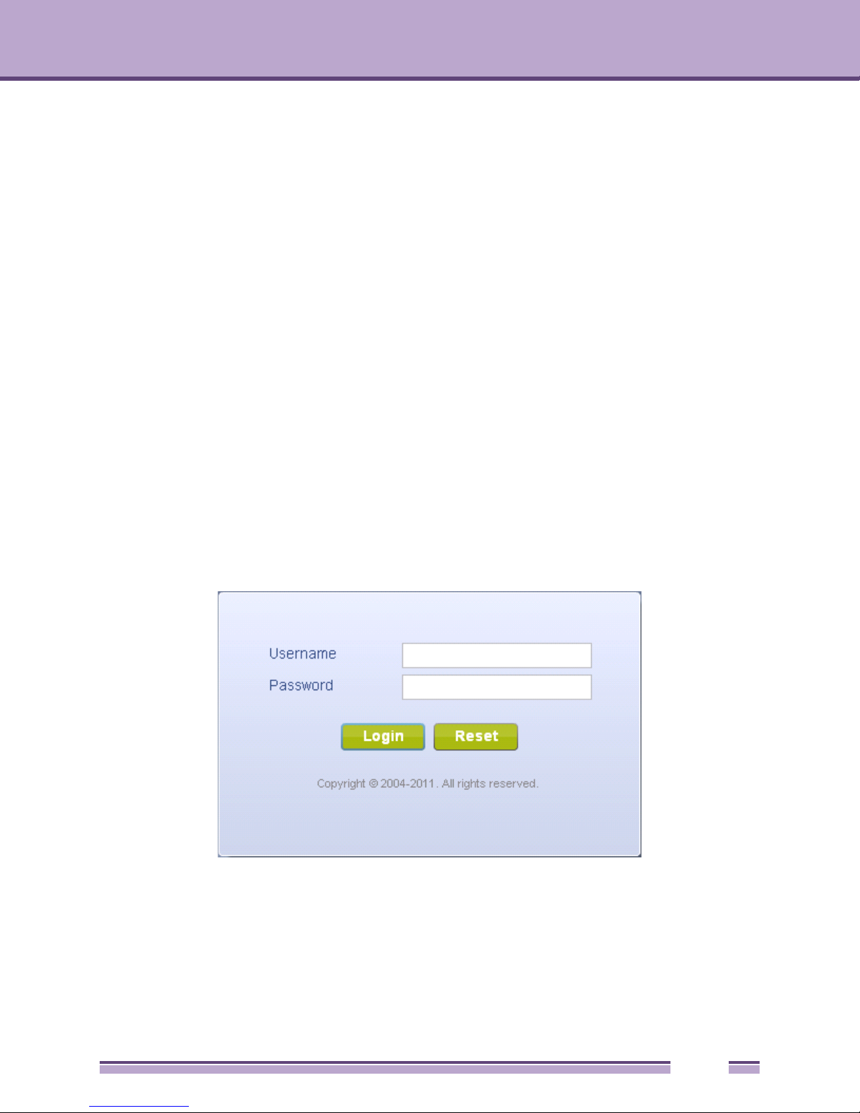
4 Point the Web browser to the access point’s zero config IP address. The following login screen
displays:
5 Enter the default username admin in the Username field.
6 Enter the default password admin123 in the Password field.
7 Select the Login button to load the management interface.
If this is the first time the management interface has been accessed, the first screen to display will
prompt for a change of the default access point password. Then, a dialogue displays to start the
16
AltitudeTM 4000 Series Access Point System Reference Guide

Glossary of Icons Used
initial setup wizard. For more information on using the initial setup wizard see “Using the Initial
Setup Wizard” on page 25.
Glossary of Icons Used
The access point interface utilizes a number of icons designed to interact with the system, gather
information from managed devices and obtain status. This chapter is a compendium of the icons used,
and is organized as follows:
● Global Icons on page 17
● Dialog Box Icons on page 18
● Table Icons on page 18
● Status Icons on page 19
● Configurable Objects on page 19
● Configuration Objects on page 22
● Configuration Operation Icons on page 22
● Access Type Icons on page 23
● Administrative Role Icons on page 23
● Device Icons on page 24
Global Icons
“Web UI Overview”
This section lists global icons available throughout the interface.
Logoff – Select this icon to log out of the system. This icon is always available
and is located at the top right-hand corner of the UI.
Add – Select this icon to add a row in a table. When this icon is selected, a new
row is created in the table, or a dialog box opens where you can enter values for
that particular list.
Delete – Select this icon to remove a row from a table. When this icon is clicked,
the selected row is immediately deleted.
More Information – Select this icon to display a pop-up with supplementary
information that may be available for an item.
Trash – Select this icon to remove a row from a table. When this icon is clicked,
the selected row is immediately deleted.
AltitudeTM 4000 Series Access Point System Reference Guide
17

Chapter 3: Web UI Overview
Create new policy – Select this icon to create a new policy. Policies define
different configuration parameters that can be applied to device configurations,
and device profiles.
Edit policy – Select this icon to edit an existing policy. To edit a policy, click on
the policy and select this button.
Dialog Box Icons
“Web UI Overview”
These icons indicate the current state of various controls in a dialog. These icons enables you to gather,
at a glance, the status of all the controls in a dialog. The absence of any of these icons next to a control
indicates the value in that control has not been modified from its last saved configuration.
Entry Updated – Indicates a value has been modified from its last saved
configuration.
Entry Update – States that an override has been applied to a device’s
profile configuration.
Mandatory Field – Indicates the control’s value is a mandatory configuration
item. You will not be allowed to proceed further without providing all
mandatory values in this dialog.
Error in Entry – Indicates there is an error in a value that has been entered
in that control. A small red popup provides a likely cause of the error.
Table Icons
“Web UI Overview”
The following two override icons are status indicators for transactions that need to be committed.
Table Row Overridden – Indicates a change (profile configuration override)
has been made to a table row, and the change will not be implemented
until saved. This icon represents a change from this device’s profile
assigned configuration.
Table Row Added – Indicates a new row has been added to a table, and
the change will not be implemented until saved. This icon represents a
change from this device’s profile assigned configuration.
18
AltitudeTM 4000 Series Access Point System Reference Guide

Glossary of Icons Used
Status Icons
“Web UI Overview”
These icons define device status, operations on the wireless controller, or any other action that requires
a status being returned to the user.
Fatal Error – States there is an error causing a managed device to stop
functioning.
Error – Indicates an error exits requiring intervention. An action has failed,
but the error is not system wide.
Warning – States a particular action has completed, but some errors were
detected that did not stop the process from completing. Intervention might
still be required to resolve subsequent warnings.
Success – Indicates everything is well within the network or a process has
completed successfully without error.
Information – This icon always precedes information displayed to the user.
This may either be a message displaying progress for a particular process,
or may just be a message from the system.
Configurable Objects
“Web UI Overview”
These icons define configurable items within the UI.
Device Configuration – Represents a configuration file applicable to a
device category.
Auto Provisioning Policy – Represents an adoption policy as a set of
configuration parameters that define how wireless clients are adopted to the
access point.
Wireless LANs – States an action impacting a WLAN has occurred.
WLAN QoS Policy – States a quality of service (QoS) policy configuration
has been impacted.
AltitudeTM 4000 Series Access Point System Reference Guide
19

Chapter 3: Web UI Overview
Radio QoS Policy – Indicates a QoS policy configuration has been
impacted.
AAA Policy – Indicates an Authentication, Authorization and Accounting
(AAA) policy has been impacted. AAA policies define RADIUS
authentication and accounting parameters.
Association ACL – Indicates an Association Access Control List (ACL)
configuration has been impacted. An ACL is a set of configuration
parameters used to set access to managed resources. The association
ACL configures the parameters for controlling device associations.
Smart RF Policy – States a Smart RF policy has been impacted. Smart RF
enables neighboring APs to take over for an AP that suddenly becomes
unavailable. This is accomplished by increasing the power of radios on
nearby APs to cover the hole created by the non-functioning AP.
Profile – States a device profile configuration has been impacted. A profile
is a collection of configuration parameters used to configure a device or a
feature.
Bridging Policy – Indicates a bridging policy configuration has been
impacted. A bridging policy defines which VLANs are bridged and how local
VLANs are bridged between the wired and wireless sides of the network.
RF Domain – States an RF Domain configuration has been impacted. RF
Domain implement location based security restrictions applicable to all
VLANs in a particular physical location.
Firewall Policy – Indicates a Firewall policy has been impacted. Firewalls
provide a barrier that prevent unauthorized access to secure resources
while allowing authorized access to external and internal resources.
IP Firewall Rules – Indicates an IP Firewall rule has been applied. An IP
based firewall rule implements firewall restrictions based on the IP address
in a received packet.
MAC Firewall Rules – States a MAC based Firewall Rule has been applied.
A MAC based firewall rule implements firewall restrictions based on the
MAC address in a received packet.
Wireless Client Role – Indicates a wireless client role has been applied to a
managed client. The role could be either sensor or client.
WIPS Policy – States the conditions of a WIPS policy have been invoked.
WIPS prevents unauthorized access to the network by checking for (and
removing) rogue APs and wireless clients.
20
AltitudeTM 4000 Series Access Point System Reference Guide

Glossary of Icons Used
Advanced WIPS Policy – States the conditions of an advanced WIPS policy
have been invoked. WIPS prevents unauthorized access to the system by
checking for and removing rogue access point’s and wireless clients.
Device Categorization – Indicates a device categorization policy is being
applied. This is used by the intrusion prevention system to categorize APs
or wireless clients as either neighbors or sanctioned devices. This enables
these devices to bypass the intrusion prevention system.
Captive Portal – States a captive portal is being applied. Captive portal is
used to provide hotspot services to wireless clients.
DNS Whitelist – A DNS whitelist is used in conjunction with captive portal to
provide hotspot services to wireless clients.
DHCP Server Policy – Indicates a DHCP server policy is being applied.
DHCP provides IP addresses to wireless clients. A DHCP server policy
configures how DHCP provides these IP addresses.
RADIUS Group – Indicates the configuration of RADIUS Group is being
defined and applied. A RADIUS group is a collection of RADIUS users with
the same set of permissions.
RADIUS User Pools – States a RADIUS user pool is being applied.
RADIUS user pools are a set of IP addresses that can be assigned to an
authenticated RADIUS user.
RADIUS Server Policy – Indicates a RADIUS server policy is being applied.
RADIUS server policy is a set of configuration attributes used when a
RADIUS server is configured for AAA.
Management Policy – Indicates a management policy is being applied.
Management policies are used to configure access control, authentication,
traps and administrator permissions.
AltitudeTM 4000 Series Access Point System Reference Guide
21

Chapter 3: Web UI Overview
Configuration Objects
“Web UI Overview”
Configuration icons are used to define the following:
Configuration – Indicates an item capable of being configured by the
access point’s interface.
View Events / Event History – Defines a list of events. Select this icon to
view events or view the event history.
Core Snapshots – Indicates a core snapshot has been generated. A core
snapshot is a file that records the status of all the processes and memory
when a process fails.
Panic Snapshots – Indicates a panic snapshot has been generated. A panic
snapshot is a file that records the status of all the processes and memory
when a failure occurs.
UI Debugging – Select this icon/link to view current NETCONF messages.
View UI Logs – Select this icon/link to view the different logs generated by
the user interface, FLEX and the error logs.
Configuration Operation Icons
“Web UI Overview”
The following icons are used to define configuration operations:
Revert – When selected, any changes made after the last saved
configuration are restored back to the last saved configuration.
Commit – When selected, all changes made to the configuration are written
to the access point. Once committed, changes cannot be reverted.
Save – When selected, changes are saved to the access point’s
configuration.
22
AltitudeTM 4000 Series Access Point System Reference Guide

Access Type Icons
“Web UI Overview”
The following icons display a user access type:
Web UI – Defines a Web UI access permission. A user with this permission
is permitted to access an associated device’s Web UI.
Telnet – Defines a TELNET access permission. A user with this permission
is permitted to access an access point using TELNET.
SSH – Indicates a SSH access permission. A user with this permission is
permitted to access an access point device using SSH.
Console – Indicates a console access permission. A user with this
permission is permitted to access using the access point’s serial console.
Glossary of Icons Used
Administrative Role Icons
“Web UI Overview”
The following icons identify the different administrative roles allowed on the system:
Superuser – Indicates superuser privileges. A superuser has complete
access to all configuration aspects of the access point to which they are
connected.
System – States system user privileges. A system user is allowed to
configure some general settings like boot parameters, licenses, auto install,
image upgrades etc.
Network – Indicates network user privileges. A network user is allowed to
configure all wired and wireless parameters, like IP configuration, VLANs,
L2/L3 security, WLANs, radios etc.
Security – Indicates security user privileges. A security level user is allowed
to configure all security related parameters.
Monitor – Defines a monitor role. This role provides no configuration
privileges. A user with this role can view all system configuration but cannot
modify them.
AltitudeTM 4000 Series Access Point System Reference Guide
23

Chapter 3: Web UI Overview
Help Desk – Indicates help desk privileges. A help desk user is allowed to
use troubleshooting tools like sniffers, execute service commands, view or
retrieve logs and reboot an access point.
Web User – Indicates a Web user privilege. A Web user is allowed
accessing the access point’s Web user interface.
Device Icons
“Web UI Overview”
The following icons indicate the different device types managed by the system:
System – This icon indicates system-wide impact.
Cluster – This icon indicates a cluster. A cluster is a set of access points
that work collectively to provide redundancy and load sharing.
Access Point – This icon indicates any access point that is a part of the
network.
Wireless Client – This icon defines any wireless client connected within the
access point managed network.
24
AltitudeTM 4000 Series Access Point System Reference Guide
Quick Start
4
CHAPTER
Access points can utilize an initial setup wizard to streamline the process of initially accessing the
wireless network. The wizard defines the access point operational mode, deployment location, basic
security, network and WLAN settings. For instructions on how to use the initial setup wizard, see
“Using the Initial Setup Wizard” on page 25.
Using the Initial Setup Wizard
Once the access point is installed and powered on, complete the following steps to get the access point
up and running and access management functions:
1 Point the Web browser to the access point’s IP address. The following login screen displays:
2 Enter the default username admin in the Username field.
3 Enter the default password admin123 in the Password field.
4 Click the Login button to load the management interface.
AltitudeTM 4000 Series Access Point System Reference Guide
25

NOTE
NOTE
NOTE
Chapter 4: Quick Start
When logging in for the first time, you’re prompted to change the password to enhance device security
in subsequent logins.
If you get disconnected when running the wizard, you can connect again with the access point’s actual
IP address (once obtained) and resume the wizard.
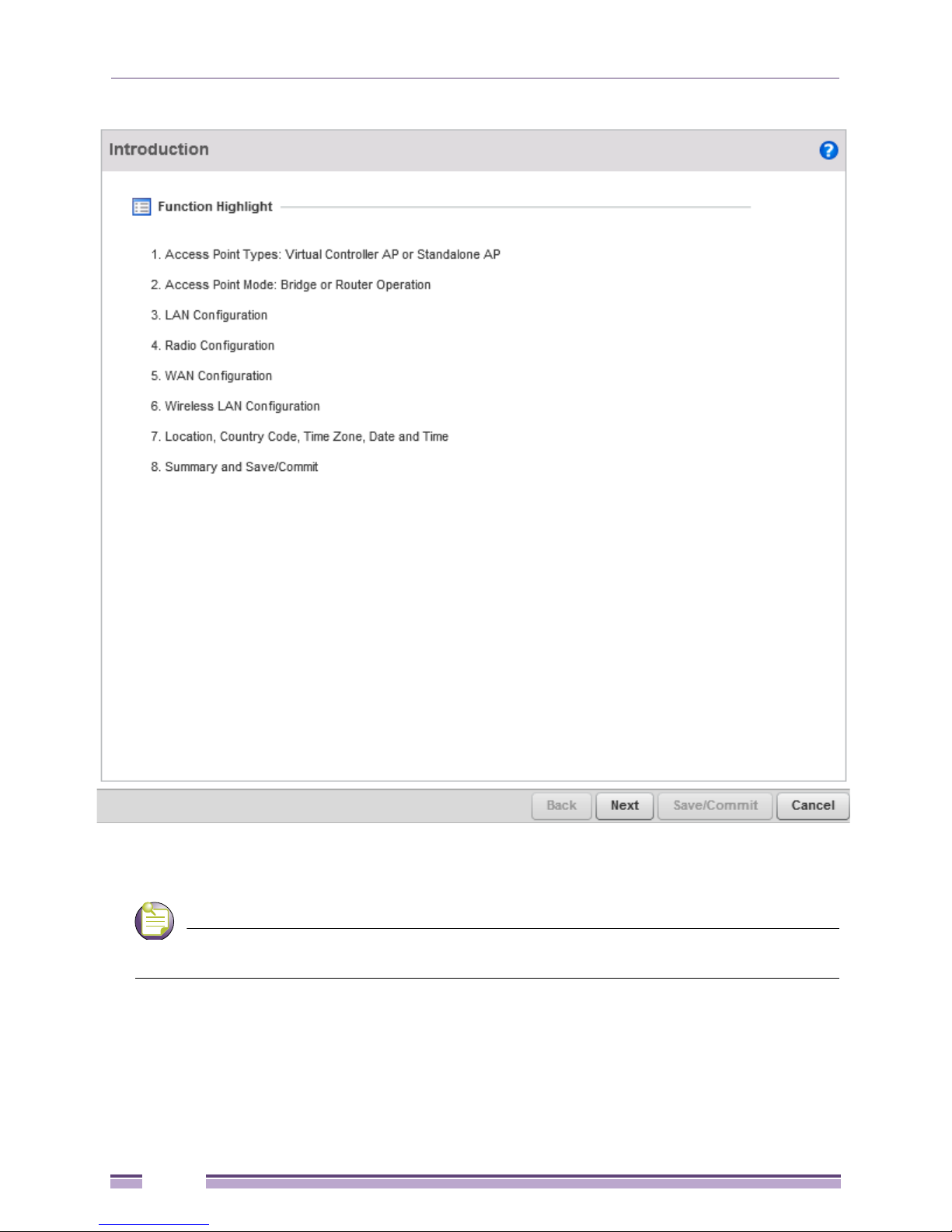
If this is the first time the access points’ management interface has been accessed, an introductory
screen displays that outlines the parameters that can be configured sequentially using the setup
wizard.
The Initial Setup Wizard displays the same pages and content for each access point model supported.
The only difference being the number of radios configurable by model.
5 Select Start Wizard to run the setup wizard. You can bypass the setup wizard and move directly to
access point’s main user interface (UI) by selecting Not Now. The setup wizard can also be disabled
until the next time the access point is rebooted by selecting Never.
26
AltitudeTM 4000 Series Access Point System Reference Guide
Using the Initial Setup Wizard
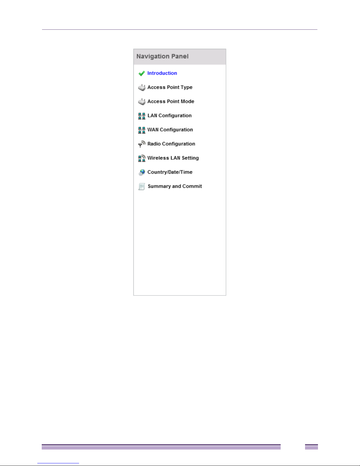
The first page of the Initial AP Setup Wizard displays the Navigation Panel and Introduction for the
configuration activities comprising the access point's initial setup.
A green checkmark to the left of an item in the Navigation Panel defines the listed task as having its
minimum required configuration parameters set correctly. A red X defines the task as still requiring
at least one parameter be defined correctly.
AltitudeTM 4000 Series Access Point System Reference Guide
27
Chapter 4: Quick Start
NOTE
6 Select Save/Commit within each page to save the updates made to that page's configuration. Select
Next to proceed to the next page listed in the Navigation Panel. Select Back to revert to the previous
screen in the Navigation Panel without saving your updates.
While you can navigate to any page in the navigation panel, you cannot complete the Initial AP Setup
Wizard until each task in the Navigation Panel has a green checkmark.
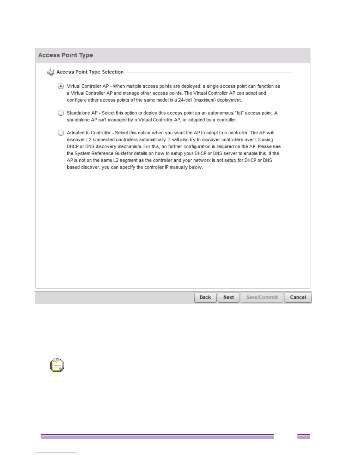
7 Select Next. The Initial AP Setup Wizard displays the Access Point Type screen to define the access
point's Standalone versus Virtual Controller AP functionality and the way the access point is
adopted to a controller.
28
AltitudeTM 4000 Series Access Point System Reference Guide
NOTE
Using the Initial Setup Wizard
8 Select an Access Point Type from the available options.
● Virtual Controller AP - When more than one access point is deployed, a single access point can
function as a Virtual Controller AP. Up to 24 Dependant APs can be connected to, and managed
by, a single Virtual Controller AP of the same model.
● Standalone AP -Select this option to deploy this access point as an autonomous fat access point. A
standalone AP isn't managed by a Virtual Controller AP, or adopted by a controller.
If designating the access point as a Standalone AP, Extreme Networks recommends the access point’s
UI be used exclusively to define its device configuration, and not the CLI. The CLI provides the ability to define
more than one profile and the UI does not. Consequently, the two interfaces cannot be used collectively to
manage profiles without an administrator encountering problems.
AltitudeTM 4000 Series Access Point System Reference Guide
29

NOTE
Chapter 4: Quick Start
● Adopted to Controller - Select this option when deploying the access point as a controller managed
(Dependent mode) access point. Selecting this option closes the Initial AP Setup Wizard. An adopted
access point obtains its configuration from a profile stored on its managing controller. Any manual
configuration changes are overwritten by the controller upon reboot.
Select the Automatic controller discovery option to enable the access point to be discovered and
adopted using layer 2 settings. If preferring layer 3 adoption, select the Static Controller Configuration
option, and define the addresses of the preferred controllers. If using the static method, you’ll also
need to define whether the access point receives an IP address using DHCP or if IP resources are
provided statically.
The best way to administer a network populated by numerous access points is to configure them
directly from the designated controller or Virtual Controller AP. If an access point’s configuration requires an
exception from the controller or Virtual Controller AP’s assigned profile configuration, the administrator should
apply a Device Override to change just that access point’s configuration.. For more information on applying an
override to an access point’s Virtual Controller AP assigned configuration profile, see “Profile Overrides” on
page 155.
9 Select Next. The Initial AP Setup Wizard displays the Access Point Mode screen to define the access
point's routing or bridging mode functionality.
30
AltitudeTM 4000 Series Access Point System Reference Guide
 Loading...