

Extreme Networks Altitude 3550 Deployment Manual
Altitude™ 3550 Access Point Deployment Guide
Extreme Networks, Inc.
3585 Monroe Street
Santa Clara, California 95051
(888) 257-3000
(408) 579-2800
http://www.extremenetworks.com
Published: December 2009
Part Number: 100351-00 Rev 01

AccessAdapt, Alpine, Altitude, BlackDiamond, EPICenter, ExtremeWorks Essentials, Ethernet Everywhere, Extreme
Enabled, Extreme Ethernet Everywhere, Extreme Networks, Extreme Standby Router Protocol, Extreme Turbodrive,
Extreme Velocity, ExtremeWare, ExtremeWorks, ExtremeXOS, Go Purple Extreme Solution, ExtremeXOS
ScreenPlay, ReachNXT, Sentriant, ServiceWatch, Summit, SummitStack, Triumph, Unified Access Architecture,
Unified Access RF Manager, UniStack, the Extreme Networks logo, the Alpine logo, the BlackDiamond logo, the
Extreme Turbodrive logo, the Summit logos, and the Powered by ExtremeXOS logo are trademarks or registered
trademarks of Extreme Networks, Inc. or its subsidiaries in the United States and/or other countries.
sFlow is a registered trademark of InMon Corporation.
Specifications are subject to change without notice.
All other registered trademarks, trademarks, and service marks are property of their respective owners.
© 2009 Extreme Networks, Inc. All Rights Reserved.
Altitude 3550 Access Point Deployment Guide2

Table of Contents
Chapter 1: About This Guide.....................................................................................................................5
Introduction..............................................................................................................................................................5
Document Conventions............................................................................................................................................5
Notational Conventions ...........................................................................................................................................5
Chapter 2: Introduction..............................................................................................................................7
Chapter 3: Mounting Kit Assembly and Use............................................................................................9
Installing the AP3550’s Mounting Accessories.......................................................................................................9
Installing the AP3550 to a Pole.............................................................................................................................11
Chapter 4: Heavy Weather Kit Assembly and Use................................................................................17
Chapter 5: Power Tap Installation..........................................................................................................21
Pre-Installation Guidelines ....................................................................................................................................21
Power Tap Installation........ .................................................................... ..... ...... ....................................................21
Chapter 6: Cable Connectors and Unused Connector Protection........................................................27
Chapter 7: Customer Support..................................................................................................................31
Registration............................................................................................................................................................31
Documentation.......................................................................................................................................................31
Altitude 3550 Access Point Deployment Guide 3

Table of Contents
Altitude 35 5 0 Access Point Deploym ent Guide4

1 About This Guide
NOTE
CAUTION
WARNING!
Introduction
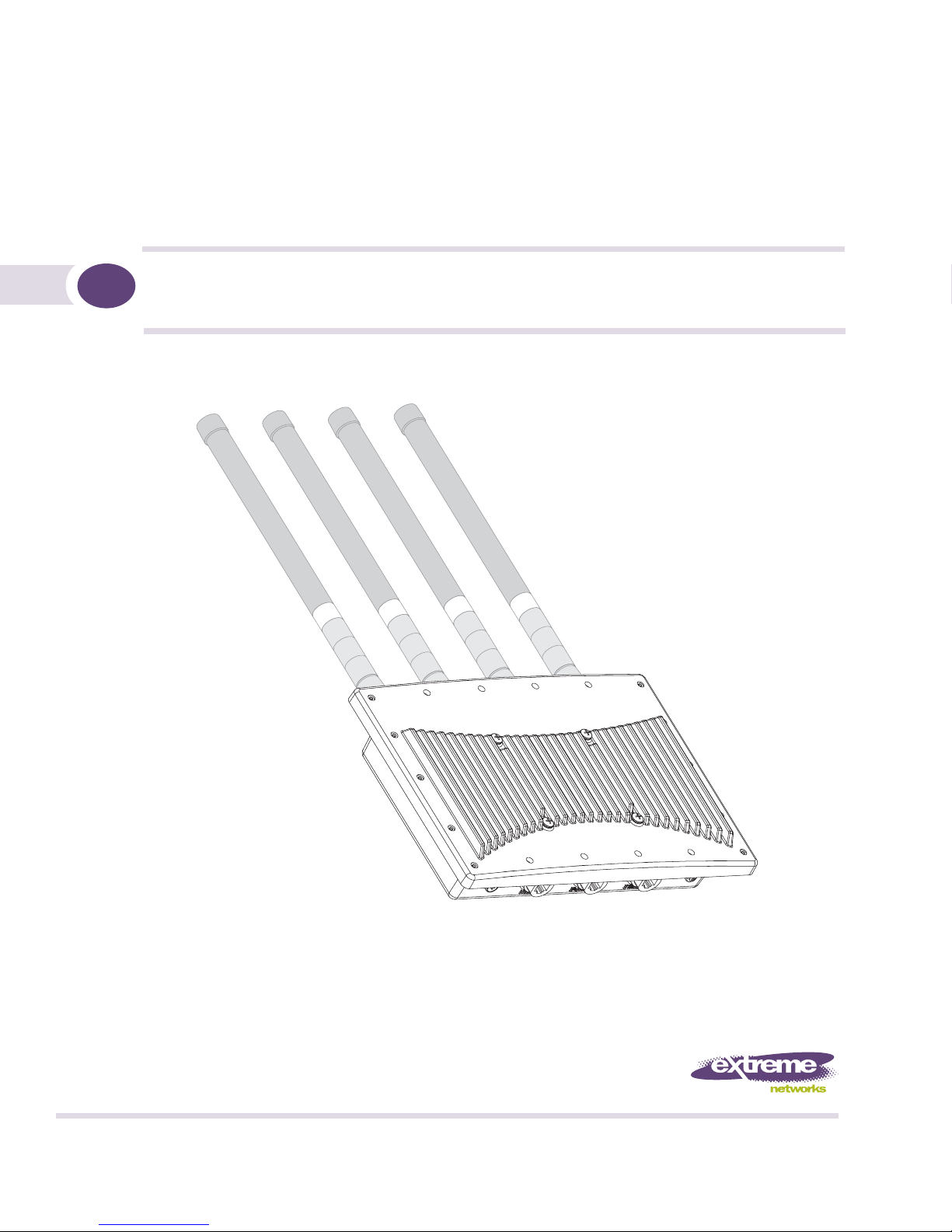
This guide provides detailed hardware setup and deployment instructions for the Extreme Networks®
Altitude
outdoor deployments, thus it has a unique set of installation instructions.
™
3550 (AP3550) model access point. The AP3550 model access point is primarily designed for
Document Conventions
The following document conventions are used in this document:
Indicate tips or special requirements.
Indicates conditions that can cause equipment damage or data loss.
Indicates a condition or procedure that could result in personal injury or equipment damage.
Notational Conventions
The following notational conventions are used in this document:
● Italics are used to highlight specific items in the general text, and to identify chapters and sections in
this and related documents.
● Bullets (•) indicate:
● action items
● lists of alternatives
● lists of required steps that are not necessarily sequential
● Sequential lists (those describing step-by-step procedures) appear as numbered lists.
Altitude 3550 Access Point Deployment Guide 5

About This Guide
Altitude 3550 Access Point Deployment Guide6

2 Introduction
Please review all the material within this document before installing the AP3550 model access point.
The purpose of this guide is to assist you in understanding the correct use and placement of the
components within the AP3550 accessory kits. Proper installation is critical to the safety of the
installation, installer and others in the area of the AP3550’s deployment.
To deploy your AP3550 model access point in an outdoor environment, refer to the following:
● “Mounting Kit Assembly and Use”
● “Heavy Weather Kit Assembly and Use”
● “Power Tap Installation”
● “Cable Connectors and Unused Connector Protection”
Altitude 3550 Access Point Deployment Guide 7

Introduction
Altitude 3550 Access Point Deployment Guide8
3 Mounting Kit Assembly and Use
NOTE
It is recommended the assembly of the AP3550’s accessories be started, and fully staged (as described in
this chapter) before the AP3550 is moved into its final area of deployment.
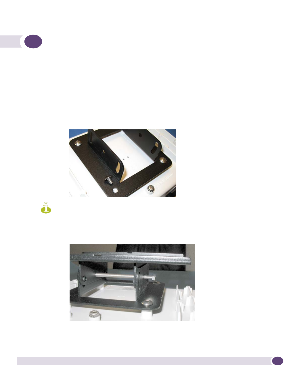
Installing the AP3550’s Mounting Accessories
To install the AP3550’s mounting accessories:
1 Install the mounting bracket to the AP3550’s rear housing using 4 short length binder head screws
from the kit. Tighten securely.
Take note of the earth ground boss under the bracket. This point must be properly grounded to earth to utilize
this products safety features. This is a good time to add the required grounding lug or cable (not included with
the AP3550 or mounting kit).
2 Install the AP3550 tilt bracket onto the AP3550’s bracket installed in step 1.
Use one long binder head screw and hex nut from the kit. This will define the pivot about which the
AP3550 can be tilted. Do not over tighten the nut.
Altitude 3550 Access Point Deployment Guide 9
Mounting Kit Assembly and Use
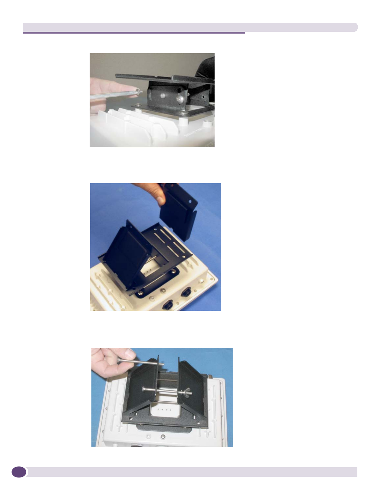
3 Install 4 short binder head screws in the 4 slots, 2 each on left and right sides of the tilt bracket.
These can be tightened during this phase of the assembly. Once deployed in the field, the 4 screws
should be loosened slightly to allow the AP3550 to be tilted to level, then re-tightened.
4 If sliding to a small pole diameter, up to 2 ½ inches in diameter, place the pole clamps into the slots
of the bracket assembled in step 3.
The pole clamps can be installed into inner or outer slots to adjust for pole diameters of various
sizes.
5 Install 2 long binder head screws through the two holes of one clamp into the other clamp. Direction
is not important.
Altitude 3550 Access Point Deployment Guide10
 Loading...