

Extreme Networks Altitude 3510 Installation Manual
Altitude™ 3510 Access Point
Installation Guide
Extreme Networks, Inc.
3585 Monroe Street
Santa Clara, California 95051
(888) 257-3000
(408) 579-2800
http://www.extremenetworks.com
Published: December 2009
Part Number: 100348-00 Rev 01

AccessAdapt, Alpine, Altitude, BlackDiamond, EPICenter, ExtremeWorks Essentials, Ethernet
Everywhere, Extreme Enabled, Extreme Ethernet Everywhere, Extreme Networks, Extreme
Standby Router Protocol, Extreme Turbodrive, Extreme Velocity, ExtremeWare, ExtremeWorks,
ExtremeXOS, Go Purple Extreme Solution, ExtremeXOS ScreenPlay, ReachNXT, Sentriant,
ServiceWatch, Summit, SummitStack, Triumph, Unified Access Architecture, Unified Access RF
Manager, UniStack, the Extreme Networks logo, the Alpine logo, the BlackDiamond logo, the
Extreme Turbodrive logo, the Summit logos, and the Powered by ExtremeXOS logo are
trademarks or registered trademarks of Extreme Networks, Inc. or its subsidiaries in the United
States and/or other countries.
sFlow is a registered trademark of InMon Corporation.
Specifications are subject to change without notice.
All other registered trademarks, trademarks, and service marks are property of their respective
owners.
© 2009 Extreme Networks, Inc. All Rights Reserved.
Altitude 3510 Access Point Installation Guide2 Altitude 3510 Access Point Installation Guide2

Table of Contents
Chapter 1: Introduction............................................................................................. 5
Document Conventions ........................................................................................ 6
Warnings............................................................................................................ 6
Site Preparation.................................................................................................. 7
Chapter 2: AP3510 Specifications ............................................................................9
Physical Characteristics....................................................................................... 9
Electrical Characteristics ..................................................................................... 9
Radio Characteristics ........................................................................................ 10
Chapter 3: Hardware Installation............................................................................. 11
Precautions ...................................................................................................... 11
Package Contents ............................................................................................. 11
AP3510 Placement........................................................................................... 12
AP3510 Antenna Options ............................................................................ 12
Powering the Access Point ........................................................................... 13
Mounting the AP3510....................................................................................... 14
Desk Mounting ........................................................................................... 14
Wall Mounting ............................................................................................ 16
Suspended Ceiling T-Bar Installations ........................................................... 18
Above the Ceiling (Plenum) Installations ....................................................... 20
LED Indicators.................................................................................................. 23
Chapter 4: Basic AP3510 Configuration ..................................................................25
Configuring Initial Settings ................................................................................ 25
Establishing Basic AP Connectivity ..................................................................... 25
Auto Discovery using DHCP.......................................................................... 26
Where to Go From Here?.................................................................................... 27
Chapter 5: Regulatory Compliance .......................................................................... 29
Country Approvals ............................................................................................. 29
Health and Safety Recommendations.................................................................. 29
Warnings for the use of Wireless Devices ....................................................... 29
Potentially Hazardous Atmospheres .............................................................. 30
Altitude 3510 Access Point Installation Guide 3

Safety in Hospitals ...................................................................................... 30
RF Exposure Guidelines..................................................................................... 30
Safety Information ...................................................................................... 30
Reducing RF Exposure—Use Properly ........................................................... 30
Remote and Standalone Antenna Configurations ............................................ 30
Power Supply ................................................................................................... 31
Wireless Devices - Countries .............................................................................. 31
Country Selection........................................................................................ 31
United States ................................................................................................... 32
FCC ........................................................................................................... 33
Radio Frequency Interference Statements................................................ 33
Radio Transmitters (Part 15) .................................................................. 33
Canada ............................................................................................................ 34
Radio Frequency Interference Statement ....................................................... 34
Radio Transmitters ...................................................................................... 34
European Economic Area (EEA).......................................................................... 35
CE Marking ................................................................................................ 35
Statement of Compliance............................................................................. 36
Declaration of Conformity in Languages of the European Community................ 37
New Member States requirements of Declaration of Conformity ....................... 38
RF safety distance ...................................................................................... 38
Conditions of use in the European community ............................................... 38
Israel ............................................................................................................... 40
Other Countries ................................................................................................ 40
Optional 3rd party external antennas............................................................. 41
Chapter 6: Waste Electrical and Electronic Equipment (WEEE) ................................. 43
Chapter 7: Customer Support ..................................................................................45
Registration...................................................................................................... 45
Documentation ................................................................................................. 45
Altitude 3510 Access Point Installation Guide4

1 Introduction
The Extreme Networks® Altitude™ 3510 Access Point (AP) provides a bridge between
Ethernet wired LANs or WANs and wireless networks. It provides connectivity between
Ethernet wired networks and radio-equipped mobile units (MUs).
The AP3510 provides a maximum 54Mbps data transfer rate via each radio. It monitors
Ethernet traffic and forwards appropriate Ethernet messages to MUs over the network.
It also monitors MU radio traffic and forwards MU packets to the Ethernet LAN.
An AP3510 can be adopted, configured and managed from a wireless controller. The
management of the AP3510 is conducted by a controller, only after the AP3510 connects
to a Summit
configuration.
The Extreme Networks AP3510 Access Point comes with a dual 802.11a+g radio and
external antenna. The AP model number is based on the regulatory domain which is
determined by the country of use:
®
WM3600 or Summit WM3700 model controller and receives its
Part Number Model Numbe r Regulatory Domain
15720 AP3510-US For use in the US only
15721 AP3510-ROW For use in Europe & Rest of World (RoW)
15723 AP3510-IL For use in Israel only
The following power adapters must be used with the above access points if PoE is not
chosen as the power source:
Part Number Model
15728 Power Supply-Altitude 3510 (for use only with AP3510 access point)
If new to the AP3510 and access point technology, refer to the Altitude 35x0 Access Point
Product Reference Guide to familiarize yourself with access point technology and the
feature set exclusive to the Extreme Networks AP3510. The guide is available, at
http://www.extremenetworks.com/go/documentation.
Altitude 3510 Access Point Installation Guide 5

Introduction
NOTE
CAUTION
WARNING!
Document Conventions
The following graphical alerts are used in this document to indicate notable situations
Tips, hints, or special requirements that you should take note of.
Care is required. Disregarding a caution can result in data loss or equipment malfunction.
Indicates a condition or procedure that could result in personal injury or equipment damage.
Warnings
● Read all installation instructions and site survey reports, and verify correct
equipment installation before connecting the AP3510 to its power source.
● Remove jewelry and watches before installing this equipment.
● Verify that the unit is grounded before connecting it to the power source.
● Verify that any device connected to this unit is properly wired and grounded.
● Connect all power cords to a properly wired and grounded electrical circuit.
● Verify that the electrical circuits have appropriate overload protection.
● Attach only approved power cords to the device.
● Verify that the power connector and socket are accessible at all times during the
operation of the equipment.
● Do not work with power circuits in dimly lit spaces.
● Do not install this equipment or work with its power circuits during thunderstorms
or other weather conditions that could cause a power surge.
● Verify there is adequate ventilation around the device, and that ambient
temperatures meet equipment operation specifications.
Altitude 3510 Access Point Installation Guide6

Site Preparation
● Consult your site survey and network analysis reports to determine specific
equipment placement, power drops, and so on.
● Assign installation responsibility to the appropriate personnel.
● Identify and document where all installed components are located.
● Provide a sufficient number of power drops for your equipment.
● Ensure adequate, dust-free ventilation to all installed equipment.
● Identify and prepare Ethernet and console port connections.
● Verify that cable lengths are within the maximum allowable distances for optimal
signal transmission.
Altitude 3510 Access Point Installation Guide 7

Introduction
Altitude 3510 Access Point Installation Guide8

2 AP3510 Specifications
Physical Characteristics
The AP3510 has the following physical characteristics:
Dimensions 5.32 inches long x 9.45 inches wide x 1.77 inches thick.
135 mm long x 240 mm wide x 45 mm thick.
Housing Metal, plenum-rated housing (UL2043)
Weight 1.95 lbs/0.88 Kg
Operating
Temperature
Storage
Temperature
Altitude 8,000 feet/2438m @ 28°F / 28°C (operating)
Vibration Vibration to withstand .02g/Hz, random, sine, 20-2k Hz
Humidity 5 to 95% (operating) 5 to 85% (storage)
Electrostatic
Discharge
Drop Bench drop 36 inches to concrete (excluding side with connectors)
-4°F to 122°F / -20°C to 50°C
-40°F to 158°F / -40°C to 70°C
15,000 feet/4572m @ 53°F / 12°C (storage)
15kV (air)
8kV (contact)
Electrical Characteristics
The AP3510 has the following input power requirements:
Nominal Operating Voltage 48V DC (Nom)
Nominal Operating Current 250mA @ 48V DC PoE (802.3af compatible)
Altitude 3510 Access Point Installation Guide 9

AP3510 Specifications
Radio Characteristics
The AP3510 has the following radio characteristics. See the datasheet for additional
radio details. The following are radio capabilities. Actual operating power, channels /
frequencies are determined by unique regulatory rules for each country certified. See
http://www.extremenetworks.com/go/rfcertification.htm for a list of countries certified. See
“Regulatory Compliance” on page 29 for additional regulatory information.
Transmit Power 802.11b/g
19 dBm +/- 1 dBm @ 1, 2, 5.5, 11 Mbps
19 dBm +/- 1 dBm @ 6 and 9 Mbps
18 dBm +/- 1 dBm @ 12 and 18 Mbps
17 dBm +/- 1 dBm @ 24 and 36 Mbps
16 dBm +/- 1 dBm @ 48 and 54 Mbps
802.11a
17 dBm +/- 1 dBm @ 6 and 9 Mbps
16 dBm +/- 1 dBm @ 12 and 18 Mbps
15 dBm +/- 1 dBm @ 24 and 36 Mbps
14 dBm +/- 1 dBm @ 48 and 54 Mbps
Operating
Channels
802.11a radio - Channels 35-165 (4920-5850 MHz)
802.11b/g radio - Channels 1-13 (2412-2472 MHz)
802.11b/g radio - Channel 14 (2484 MHz Japan only)
Actual operating frequencies depend on regulatory rules
and certification agencies.
Radio Data Rates 802.11a radio 6, 9, 12, 18, 24, 36, 48, and 54 Mbit/Sec
802.11g radio 6, 9, 12, 18, 24, 36, 48, and 54 Mbit/Sec
802.11b radio 1, 2, 5.5, 11 Mbps
Wireless Medium Direct Sequence Spread Spectrum (DSSS)
Orthogonal Frequency Division Multiplexing (OFDM)
Altitude 3510 Access Point Installation Guide10

3 Hardware Installation
An AP3510 installation includes mounting the AP3510 on a table-top, wall, ceiling T-bar
or above the ceiling orientation, connecting the AP3510 to the network (LAN or WAN
port connection), connecting antennas and applying power. Installation procedures vary
for different environments.
Precautions
Before installing the AP3510 verify the following:
● Do not install in wet or dusty areas without additional protection. Contact an
Extreme Networks representative for more information.
● Verify the environment has a continuous temperature range between -20° C to 50° C.
Package Contents
Check package contents for the correct model AP3510 depending on your country of
application and applicable AP3510 accessories. Each available configuration (at a
minimum), contains:
● AP3510 Dual 802.11a+g radio, external antenna. The part number is dependent on
the regulatory domain:
Part Number Model Numbe r Regulatory Domain
15720 AP3510-US For use in the US only
15721 AP3510-ROW For use in Europe & Rest of World (RoW)
15723 AP3510-IL For use in Israel only
● Altitude 3510 Access Point Installation Guide
● Accessories Bag (4 rubber feet for desk mounting and an LED light pipe and badge
with label for above the ceiling installations)
Verify the model indicated on the bottom of the AP3510 is correct. Contact the Extreme
Networks Support Center to report missing or improperly functioning items.
Altitude 3510 Access Point Installation Guide 11

Hardware Installation
NOTE
AP3510 Placement
For optimal performance, install the AP3510 away from transformers, heavy-duty
motors, fluorescent lights, microwave ovens, refrigerators and other industrial
equipment. Signal loss can occur when metal, concrete, walls or floors block
transmission. Install the AP3510 in open areas or add access points as needed to
improve coverage.
Place the AP3510 using the following guidelines:
● Install the AP3510 at an ideal height of 10 feet from the ground.
● Orient the AP3510 antenna vertically for best reception.
● Point the AP3510 antenna(s) downward if attaching to the ceiling.
Extreme Networks recommends conducting a site survey to define and document radio
interference obstacles before installing the AP3510 to maximize its radio coverage area.
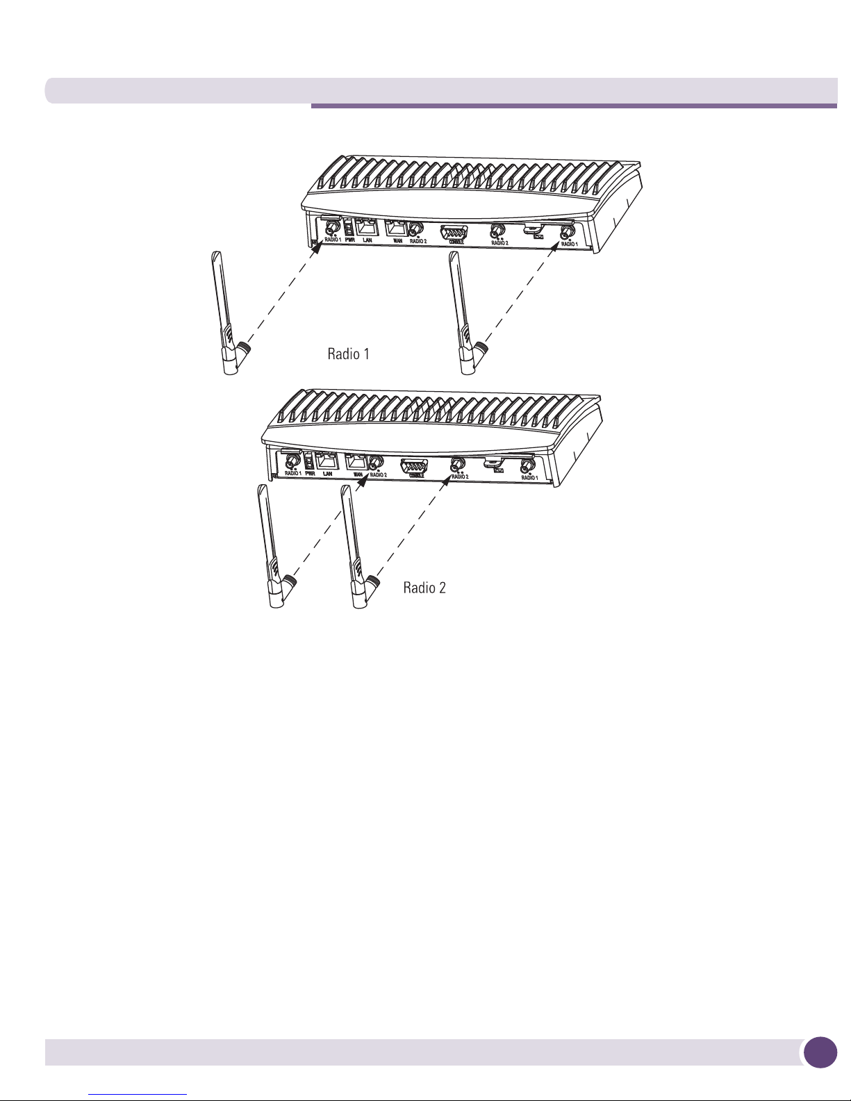
AP3510 Antenna Options
Both Radio 1 and Radio 2 require one antenna and can optimally use two antennas per
radio. Two antennas per radio provides diversity that can improve performance and
signal reception. The AP3510 is shipped with four dualband, omnidriectional paddle
antennas for indoor use. The nominal net gain for the antenna is 3.0dBi on a 2.4 GHz
radio and 4.0dBi on a 5GHz radio. For more information on the antenna options
available to the AP3510, refer to the Altitude™ 35xx/45xx AP Antenna Selection Guide
available from
On an AP3510, Radio 1 refers to the AP3510’s 2.4 GHz radio and Radio 2 refers to the AP3510
5.2 GHz radio. However, there could be some cases where an AP3510 is performing a Rogue AP
detector function. In this scenario, the AP3510 is receiving in either 2.4 GHz or 5.2 GHz over the
Radio 1 or Radio 2 antennas depending on which radio is selected for the scan.
Antenna connectors for Radio 1 are located in a different location from the Radio 2
antenna connectors.
http://www.extremenetworks.com/go/documentation.
Altitude 3510 Access Point Installation Guide12
Powering the Access Point
The AP3510 can receive power in one of three ways:
● Power over Ethernet (PoE) - If your network is already set up with PoE (802.3af
compliant), attach the LAN Ethernet cable to the AP3510’s LAN port.
● Power over Ethernet: Adding PoE injector - If your network is not set up with PoE,
you can provide power to the Ethernet cable with a PoE injector. The PoE injector
must be 802.3af compliant. The PoE injector is not provided with the AP3510.
● Power by AC adaptor - Extreme Network's 48V AC-DC power supply (Part No.
15728) can be used to power the AP3510. It is not included in the kit and is
orderable separately as an accessory.
Altitude 3510 Access Point Installation Guide 13
Hardware Installation
CAUTION
The AP3510 supports any standards-based 802.3af compliant power source. However, using the
wrong solution could severely damage the AP3510 and void the product warranty.
Mounting the AP3510
The AP3510 can rest on a flat surface, attach to a wall, mount under a suspended T-Bar
or above a ceiling (plenum or attic). Choose one of the following mounting options
based on the physical environment of the coverage area. Do not mount the AP3510 in a
location that has not been approved in a site survey.
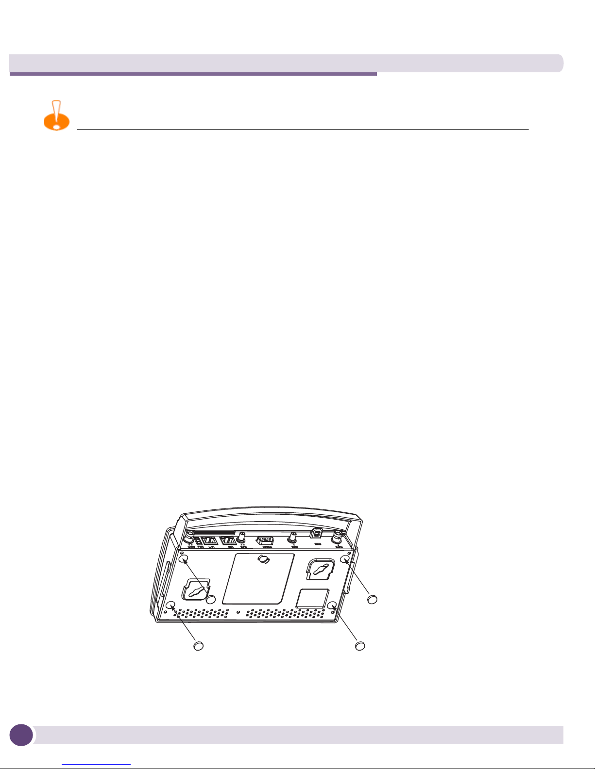
Desk Mounting
The desk mount option uses rubber feet (found in the accessories bag shipped with the
AP3510) allowing the unit to sit on most flat surfaces.
To install the AP3510 in a desk mount orientation:
1 Turn the AP3510 upside down.
2 Remove the backings from the four (4) rubber feet and attach them to the four
rubber feet recess areas on the AP3510.
3 Attach the Radio 1 and Radio 2 antennas to their correct connectors. The antenna
covers will most likely need to be removed to orient the antenna upward in a typical
desktop installation.
Altitude 3510 Access Point Installation Guide14
 Loading...