

Extreme Networks Altitude 350-2 Installation Manual
1 Extreme Networks Copyright 2007 All Rights reserved. Part Number 120390-00 Rev 01 2
Altitude AP Installation Guide
Altitude AP Installation Guide
Unpacking and mounting the Altitude AP
NOTE
For AltitudeTM 350-2 Detachable Antenna, attach the antennae to th e RP-SMA connectors in each
side of the Altitude AP before mounting on its bracket.
Connecting and powering the Altitude AP
WARNING!
This device must not be connected to a LAN segment with outdoor wiring. Ensure that all cables are
run correctly to avoid strain. Replace the power supply adapter immediately, if it shows any signs of
damage.
NOTE
Powering up the Altitude AP initiates its automatic discovery and registration proc ess with the Summit
WM Wireless Switch. The parameters for this process should be set in the user interface (AP
Registration) as explained in the User Guide.
4 Power up the Altitude AP in one of three ways:
Power Over Ethernet (PoE)
If your network is already set up with PoE (802.3af compliant), attach the LAN ethernet
cable to the RJ45 ethernet connector in the top of the Altitude AP.
Power Over Ethernet: Adding PoE Injector
If your network is not set up with PoE, you can provide power to the ethernet cable with a
PoE injector. The PoE injector must be 802.3af compliant. The PoE injector is not provided
with the Altitude AP.
Power by AC Adaptor
An AC adaptor is not provided with the Altitude AP.
Specifications: Input: 120-240 VAC, Output Voltage DC +6V, max amps 1.50, max watts 10.
To use an adaptor, install the Altitude AP within six feet of a wall outlet, attach the
adaptor to the Altitude AP and then plug the adaptor into the wall outlet.
Use only a safety approved POE injector or a safety approved Limited Power Source (Class
2) AC adaptor.
NOTE
For installations that use Receive diversity (the default), the antennae should be pointed in the same
direction. For installations that do NOT use Receive diversity, or for those that split the 802.11a and
802.11b/g radio onto different physical ports, then the antennae can be pointed in whatever direction
is desired.
The Altitude AP has two models:
• AltitudeTM 350-2 Integrated Antenna: internal dual
(multimode) diversity antennae
• Altitude
TM
350-2 Detachable Antenna: dual external
antennae, RP-SMA connectors
Unpack the Altitude AP from its carton. Also in the carton
are:
• one wall mounting bracket
• 3 screws and 3 wall plugs
• one plastic rivet (to secure Altitude AP to bracket)
For Altitude
TM
350-2 Detachable Antenna, the dual external
antennae are also included.
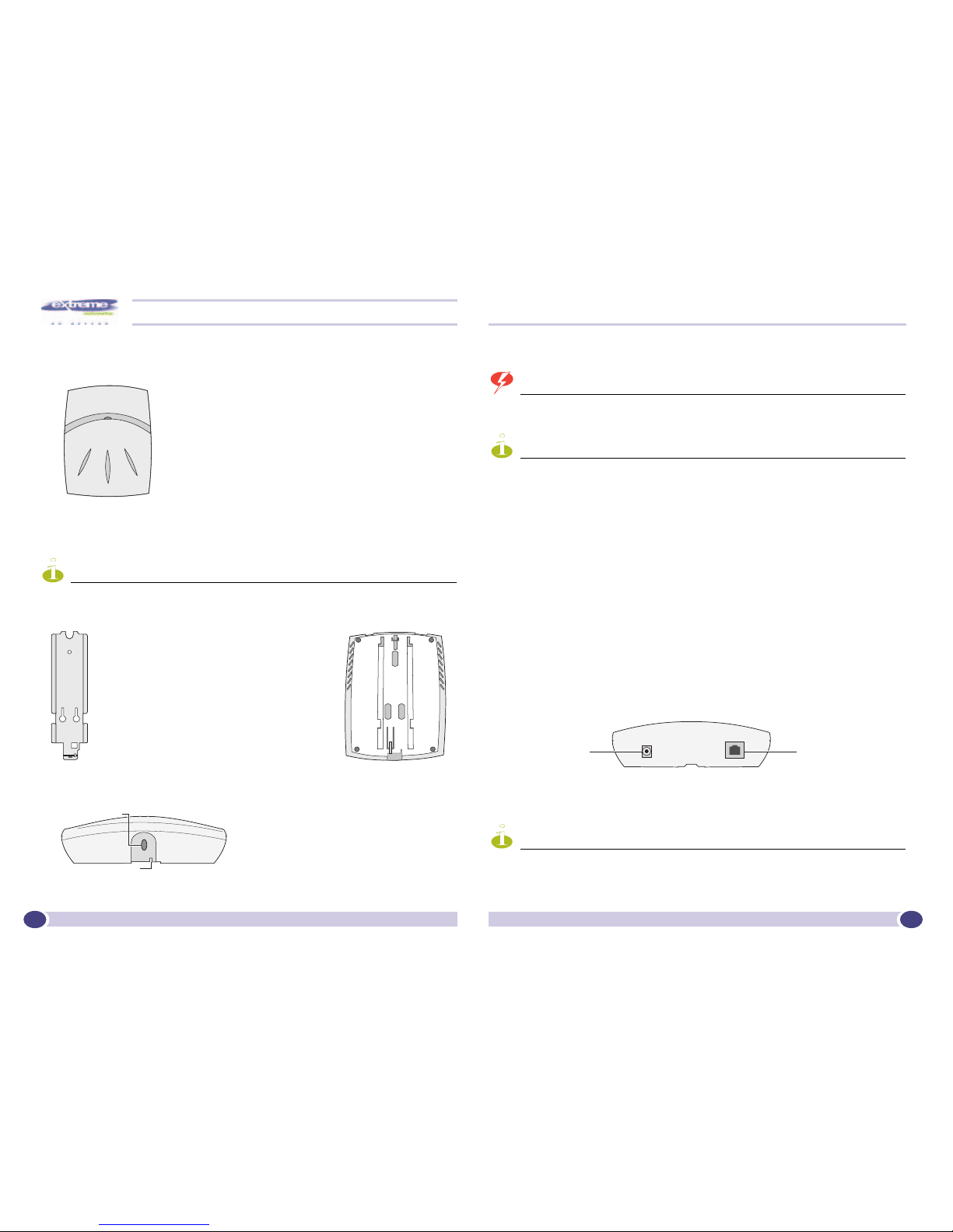
1 Mount the Altitude AP wall bracket, using 3
screws. Mount it near the LAN ethernet cable
plug coming from the wall.
2 Press the back of the Altitude AP onto the
bracket, aligning it with the open notches in
the bracket. Then slide it down until the
security spring clip holds it in place.
Security Note #1: To remove the Altitude AP,
release the spring clip by inserting an Allen key
(or other similar tool) into the small hole at the
bottom of the bracket. Then slide the case up
the bracket and lift off the Altitude AP.
3 Using a screwdriver, insert the plastic
rivet through the hole at the bottom of
the bracket and into the Altitude AP
case. This locks the case to the bracket.
Security Note #2: To remove the Altitude AP, use a screwdriver to take out
the rivet.
Opening for Allen key
Opening for rivet
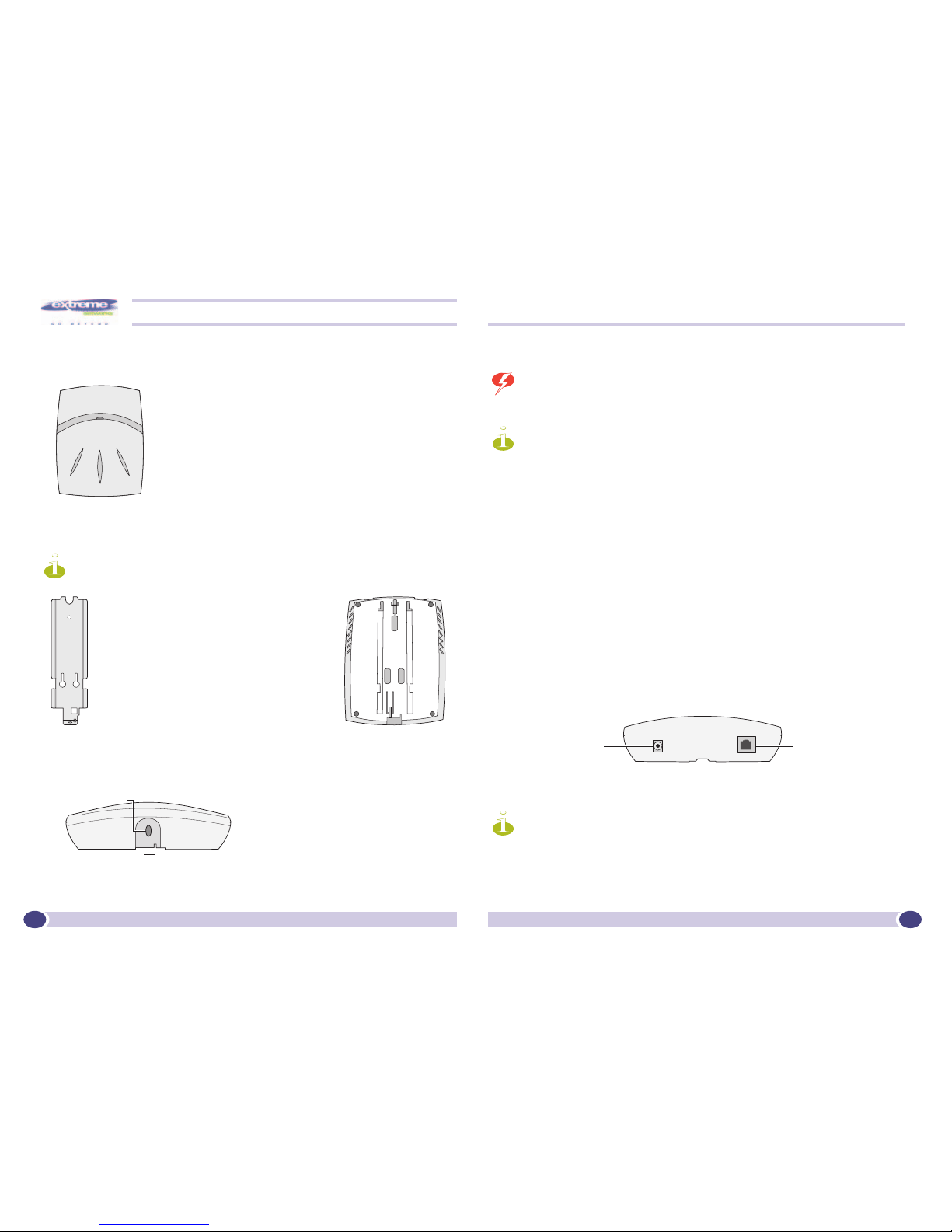
[Optional] Connect
an AC/DC power
supply (if PoE is not
being used in your
network.
In the top of the
Wireless AP,
connect the LAN
ethernet cable to
the ethernet port.
[Optional] Connect
an AC/DC power
supply (if PoE is not
being used in your
network).
In the top of the
Altitude AP, connect
the LAN ethernet cable
to the ethernet port.
1 Extreme Networks Copyright 2007 Alle Rechte vorbehalten Part Number 120390-00 Rev 01 2
AP Installationshandbuch
AP Installationshandbuch
Auspacken und montieren des Altitude AP
Hinweis: Schließen Sie beim AltitudeTM 350-2 Detachable Antenna die Antennen an die RP-
SMA-Stecker an beiden Seiten des Altitude AP an, bevor Sie ihn an der Halterung montieren.
Sicherheitshinweis 1: Um den Altitude AP zu entfernen, lösen Sie die Sicherungsklammer,
indem Sie einen Inbusschlüssel (oder ein ähnliches Werkzeug) in die kleine Öffnung an der
Unterseite der Halterung einführen und die Klammer herunterdrücken. Schieben Sie dann
das Altitude AP-Gehäuse nach oben und heben Sie es von der Halterung ab.
Sicherheitshinweis 2: Um den Altitude AP zu entfernen, nehmen Sie den Niet mit einem
Schraubendreher heraus.
Anschlüsse und stromversorgung für den Altitude AP
Warnung: Dieses Gerät darf nicht über Außenverdrahtung an ein LAN-Segment angeschlossen
werden. Stellen Sie sicher, dass alle Kabel korrekt geführt werden, um Zugbelastung zu
vermeiden. Sollte das Netzteil Anzeichen von Beschädigung aufweisen, tauschen Sie es sofort
aus.
Hinweis: Bei Einschaltung des Altitude AP wird automatisch der Erkennungs- und
Registrierungsprozess mit dem Summit WM Wireless Switch initiiert. Die Parameter für diesen
Prozess sind in der Benutzeroberfläche (AP Registration) gemäß der Beschreibung im
Bedienerhandbuch festzulegen.
4 Die Stromversorgung des Altitude AP kann auf drei Arten erfolgen:
Power-over-Ethernet (PoE)
Wenn Ihr Netzwerk bereits mit PoE (802.3af-kompatibel) eingerichtet ist, schließen Sie das
LAN-Ethernet-Kabel an die RJ45-Ethernet-Buchse an der Oberseite des Altitude AP an.
Power-over-Ethernet: PoE-Injector hinzufügen
Wenn Ihr Netzwerk nicht mit PoE eingerichtet ist, können Sie die Stromversorgung des
Ethernet-Kabels mit einem PoE-Injector bereitstellen. Der PoE-Injector muss 802.3afkompatibel sein. Der PoE-Injector ist nicht im Lieferumfang des Altitude AP enthalten.
Stromversorgung über AC-Adapter (externes Netzteil)
Der AC-Adapter ist nicht im Lieferumfang des Altitude AP enthalten.
Spezifikationen: Eingangsspannung: 120-240 VAC, Ausgangsspannung DC +6V,
Max. Stromstärke 1,5 A, Max. Leistung 10 W.
Wenn Sie einen Adapter verwenden, installieren Sie den Altitude AP ca. 1,5 bis 2 m von
einer Wandsteckdose entfernt, schließen Sie den Altitude AP an den Adapter und dann
den Adapter an die Wandsteckdose an.
Bitte verwenden Sie nur einen zugelassenen PoE-Injector bzw. eine zugelassene
leistungsbegrenzte Stromversorgung (Klasse 2).
Hinweis: Bei Install*ionen mit Empfangs-Diversity (Standard) sollten die Antennen in die
gleiche Richtung zeigen. Bei Installationen, die NICHT Empfangs-Diversity verwenden oder
den 802.11a- und 802.11b/g-Funk auf unterschiedliche physische Ports aufteilen, können die
Antennen in jede gewünschte Richtung zeigen.
Der Altitude AP ist in zwei Modellen lieferbar:
• Altitude
TM
350-2 Integrated Antenna: interne Dualband
(Multimode) Diversity-Antennen
• Altitude
TM
350-2 Detachable Antenna: externe Dualband-
Antennen, RP-SMA-Stecker
Nehmen Sie den Altitude AP aus der Verpackung. In dem
Verpackungskarton befinden sich auch:
• eine Wandhalterung
• 3 Schrauben und 3 Dübel
• ein Plastikniet (zum Befestigen des Altitude AP an der
Halterung)
Beim Altitude
TM
350-2 Detachable Antenna sind außerdem die
externen Dualband-Antennen enthalten.
1 Montieren Sie die Altitude AP-Wandhalterung
mit den 3 vorgesehenen Schrauben. Bringen
Sie sie in der Nähe des aus der Wand
austretenden LAN-Ethernet-Kabelsteckers an.
2 Drücken Sie die Rückseite des Altitude AP-
Gehäuses so auf die Halterung, dass es in die
Aussparungen der Halterung passt. Schieben
Sie das Gehäuse herunter, bis die
Sicherungsklammer einrastet und es festhält.
3 Führen Sie den Plastikniet mit Hilfe eines
Schraubenziehers durch die Öffnung an
der Unterseite der Halterung in das
Altitude AP-Gehäuse ein. Dadurch wird
das Gehäuse mit der Halterung fest
verbunden.
Öffnung für niet
Öffnung für inbusschlüssel
[Optional]. Anschluss
eines externen
Netzteils (wenn in
Ihrem Netzwerk kein
PoE verwendet wird).
Anschluss des LANEthernet-Kabels an
den Ethernet-Port an
der Oberseite des
Altitude AP.
 Loading...