

Extreme Networks Alpine 3804, Alpine 3802, Alpine 3808, Alpine 3800 Hardware Installation Manual

Alpine 3800 Series
Switch Hardware
Installation Guide
Extreme Networks, Inc.
3585 Monroe Street
Santa Clara, California 95051
(888) 257-3000
http://www.extremenetworks.com
Published: March 2000
Part number: 100054-00 Rev. A

©2000 Extreme Networks, Inc. All rights reserved. Extreme Networks and BlackDiamond are registered
trademarks of Extreme Networks, Inc. in the United States and certain other jurisdictions.
ExtremeWare, ExtremeWare Vista, ExtremeWorks, ExtremeAssist, ExtremeAssist1, ExtremeAssist2,
PartnerAssist, Extreme Standby Router Protocol, ESRP, SmartTraps, Alpine, Summit, Summit1,
Summit4, Summit4/FX, Summit7i, Summit24, Summit48, Summit Virtual Chassis, SummitLink,
SummitGbX, SummitRPS and the Extreme Networks logo are trademarks of Extreme Networks, Inc.,
which may be registered or pending registration in certain jurisdictions. The Extreme Turbodrive logo
is a service mark of Extreme Networks, which may be registered or pending registration in certain
jurisdictions. All other registered trademarks, trademarks and service marks are property of their
respective owners. Specifications are subject to change without notice.
ii

Contents
PREFACE
Introduction xi
Conventions xii
Related Publications xiii
1ALPINE 3800 SERIES SWITCH OVERVIEW
Summary of Features 1-1
Port Connections 1-3
Media Types and Distances 1-4
Full-Duplex 1-5
Alpine 3800 Series Switch Components 1-6
Alpine 3804 Switch 1-6
Alpine 3808 Switch 1-7
Alpine 3800 Series Switch Power Supply 1-8
Power Supply LEDs 1-8
Switch Management Module 1-9
SMMi Memory 1-10
SMMi LEDs 1-10
Alpine 3800 Series Switch Fan Tray 1-11
I/O Module Cards 1-11
GM-4Ti Module 1-11
GM-4Xi Module 1-13
GM-4Si Module 1-14
FM-32Ti Module 1-15
FM-24Fi Module 1-16
iii

I/O Module LEDs 1-16
Alpine 3804 Switch Rear View 1-17
Alpine 3808 Switch Rear View 1-18
2INSTALLATION AND SETUP
Following Safety Information 2-1
Determining the Switch Location 2-2
Installing the Alpine 3800 series switch 2-2
Installing the Alpine 3800 series switch components 2-6
Installing the Power Supplies 2-6
Installing Module Cards 2-7
Powering On the System 2-9
Checking the Installation 2-9
Connecting Equipment to the Console Port 2-9
Logging In for the First Time 2-11
3SERVICE AND MAINTENANCE
Following Safety Information 3-1
Removing and Replacing a Module Card 3-2
Removing and Replacing a Power Supply 3-3
Removing and Replacing an Alpine 3804 Power Supply 3-3
Removing and Replacing an Alpine 3808 Power Supply 3-5
Removing and Replacing the Fan Tray 3-7
Removing and Replacing the Alpine 3804 Fan Tray 3-7
Removing and Replacing the Alpine 3808 Fan Tray 3-9
Adding and Removing SODIMMs 3-11
Adding and Removing GBICs 3-12
ASAFETY INFORMATION
Important Safety Information A-1
Power A-1
Power Cord A-2
Connections A-3
Lithium Battery A-3
iv

BTECHNICAL SPECIFICATIONS
INDEX
v

vi

Figures
1-1 Alpine 3804 switch 1-6
1-2 Alpine 3808 Switch 1-7
1-3 Switch Management Module (SMMi) 1-9
1-4 SMMi SODIMM sockets 1-10
1-5 GM-4Ti module 1-12
1-6 GM-4Xi module 1-13
1-7 GM-4Si module 1-14
1-8 FM-32Ti module 1-15
1-9 FM-24Fi module 1-16
1-10 Alpine 3804 switch rear view 1-17
1-11 Alpine 3808 switch rear view 1-18
2-1 Rack-mount helper bracket 2-3
2-2 Alpine 3804 chassis mounted in rack 2-4
2-3 Alpine 3808 chassis mounted in rack 2-5
2-4 Power supply bays 2-6
2-5 SMMi with extended ejector/injector handles 2-8
2-6 Null-modem cable pinouts 2-10
2-7 PC-AT serial null-modem cable pinouts 2-11
3-1 Alpine 3804 power supply 3-4
3-2 Alpine 3808 power supply 3-5
3-3 Removing the Alpine 3804 fan tray 3-7
3-4 Alpine 3804 fan tray 3-8
3-5 Removing the fan tray 3-9
3-6 Alpine 3808 fan tray 3-10
3-7 Adding a SODIMM 3-11
3-8 GBIC connectors 3-12
vii

viii

Ta bl e s
1 Notice Icons xii
2 Tex t C on ve nt io ns xi i
1-1 Media Types and Distances 1-4
1-2 1000BASE-LX70 Specifications 1-5
1-3 1000BASE-SX and 1000BASE-LX Specifications 1-5
1-4 Power Supply LEDs 1-8
1-5 SMMi LEDs 1-10
1-6 I/O Module LEDs 1-16
2-1 Console Connector Pinouts 2-10
ix

x

Preface
This Preface provides an overview of this guide, describes guide conventions, and lists
other publications that may be useful.
NTRODUCTION
I
This guide provides the required information to install the Alpine™ 3800 series switch.
This guide is intended for use by network administrators who are responsible for
installing and setting up network equipment. It assumes a basic working knowledge of:
A
LPINE
• Local Area Networks (LANs)
• Ethernet concepts
• Ethernet switching and bridging concepts
• Routing concepts
• Simple Network Management Protocol (SNMP)
For information on configuring the Alpine 3800 series switch, refer to the ExtremeWare
Software User Guide.
If the information in the “Release Notes” shipped with your switch differs from the
information in this guide, follow the “Release Notes.”
ERIES SWITCH HARDWARE INSTALLATION GUIDE XI
3800 S
REFACE
P
C
ONVENTIONS
Ta bl e 1 and Tab l e 2 list conventions used throughout this guide.
Tabl e 1: Notice Icons
Icon Notice Type Alerts you to...
Note Important features or instructions.
Caution Risk of personal injury, system damage,
or loss of data.
Warning Risk of severe personal injury.
Tabl e 2: Text Conventions
Convention Description
Screen displays
Screen displays bold
The words “enter”
and “type”
[Key] names Key names appear in text in one of two ways:
Words in
italicized
type Italics emphasize a point or denote new terms at the place where
This typeface represents information as it appears on the screen,
or command syntax.
This typeface represents commands that you type.
When you see the word “enter” in this guide, you must type
something, and then press the Return or Enter key. Do not press
the Return or Enter key when an instruction simply says “type.”
■
Referred to by their labels, such as “the Return key” or “the
Escape key”
■
Written with brackets, such as [Return] or [Esc]
If you must press two or more keys simultaneously, the key
names are linked with a plus sign (+). Example:
Press [Ctrl]+[Alt]+[Del].
they are defined in the text.
XII
A
LPINE
ERIES SWITCH HARDWARE INSTALLATION GUIDE
3800 S

ELATED PUBLICATIONS
R
ELATED PUBLICATIONS
R
The Alpine documentation set includes the following:
• ExtremeWare Software User Guide
• ExtremeWare Quick Reference Guide
Documentation for Extreme Networks products is available on the World Wide Web at
the following location:
• http://www.extremenetworks.com/support/documentation.asp
LPINE
A
ERIES SWITCH HARDWARE INSTALLATION GUIDE XIII
3800 S

REFACE
P
XIV
A
LPINE
ERIES SWITCH HARDWARE INSTALLATION GUIDE
3800 S

1
Alpine 3800 Series Switch
Overview
The Alpine 3800 series switch is a chassis-based, Ethernet service provisioning switch
designed for edge and aggregation applications. The Alpine 3800 series switch is
flexible and scalable, making it easy for you to meet the changing requirements of your
network. The combination of BlackDiamond, Alpine, and Summit switches delivers a
consistent end-to-end network solution that provides a nonblocking architecture,
wire-speed switching, wire-speed IP routing, and policy-based Quality of Service (QoS).
This chapter describes the following:
• Alpine 3800 series switch features
• Network configurations using the Alpine 3800 series switch
• Alpine 3800 series switch components
UMMARY OF FEATURES
S
The features of the Alpine 3800 series switch include the following:
• A 5-slot or 9-slot chassis that can be populated with up to 4 or 8 input/output (I/O)
modules and one Switch Management Module (SMMi)
• I/O modules are hot-swappable, and include Gigabit Ethernet or 10/100 Mbps
Ethernet ports
• Redundant, load-sharing, hot-swappable power supplies
• Field-replaceable, hot-swappable fan tray
Alpine 3800 Series Switch Hardware Installation Guide 1-1

A
LPINE
ERIES SWITCH OVERVIEW
3800 S
• Up to 128 switched 10BASE-T/100BASE-TX Ethernet ports (model 3804), or up to
256 switched 10BASE-T/100BASE-TX Ethernet ports (model 3808)
• Up to 96 switched 100BASE-FX Fast Ethernet ports (model 3804), or up to 192
switched 100BASE-FX Fast Ethernet ports (model 3808)
• Up to 16 switched Gigabit Ethernet ports (model 3804), or up to 32 switched Gigabit
Ethernet ports (model 3808)
• Fully nonblocking operation
— All ports transmit and receive packets at wire speed
• Autonegotiation for half- or full-duplex operation on 10/100 Mbps ports
• Load-sharing on multiple ports
• Virtual local area networks (VLANs), including support for IEEE 802.1Q
• Spanning Tree Protocol (STP) (IEEE 802.1D) with multiple STP domains
• Policy-Based Quality of Service (QoS)
• Wire-speed Internet Protocol (IP) routing
• IP Multinetting
• Dynamic Host Configuration Protocol/Bootstrap Protocol (DHCP/BOOTP) Relay
• Routing Information Protocol (RIP) version 1 and RIP version 2
• Open Shortest Path First (OSPF) routing protocol
• IPX routing, including RIP and Service Advertisement Protocol (SAP)
• Wire-speed IP multicast routing support
• Internet Group Multicast Protocol (IGMP) and IGMP snooping
• Distance Vector Multicast Routing Protocol (DVMRP)
• IGMP snooping to control IP multicast traffic
• Console (RS-232) command-line interface (CLI) connection
• Telnet CLI connection
• ExtremeWare
™
Vista™ Web-based management interface
• Simple Network Management Protocol (SNMP) support
• Dedicated 10BASE-T/100BASE-TX port for out-of-band management via CLI,
ExtremeWare Vista, and/or SNMP
1-2 Alpine 3800 Series Switch Hardware Installation Guide

S
P
ORT CONNECTIONS
Both Alpine 3800 series switches support the following I/O modules:
• GM-4Ti module
The GM-4Ti module has four Gigabit Ethernet ports, using standard RJ-45
connectors. The GM-4T module supports autonegotiation of
100BASE-TX/1000BASE-T.
• GM-4Xi module
The GM-4Xi module has four Gigabit Ethernet ports, using standard Gigabit
Interface Connectors (GBICs). The GM-4Xi module supports 1000BASE-SX,
1000BASE-LX, and 1000BASE-LX70 GBIC modules.
• GM-4Si module
The GM-4S imodule has four Gigabit Ethernet ports, using standard MT-RJ
connectors. The GM-4Si module supports 1000BASE-SX only.
• FM-32Ti module
UMMARY OF FEATURES
The FM-32Ti module has 32 10/100 Mbps autonegotiating Ethernet ports, using
standard RJ-45 connectors. The FM-32Ti module supports 10BASE-T and
100BASE-TX.
• FM-24Fi module
The FM-24Fi module has 24 100 Mbps Ethernet ports, using standard MT-RJ
connectors. The FM-24Fi module supports 100BASE-FX in full-duplex mode only.
Caution: Modules that use SX, LX, LX70, and FX interfaces contain Class 1
laser devices. Invisible laser radiation can occur when open. Avoid direct eye
exposure to beam.
Alpine 3800 Series Switch Hardware Installation Guide 1-3

A
LPINE
ERIES SWITCH OVERVIEW
3800 S
MEDIA TYPES AND DISTANCES
Ta bl e 1 -1 describes the media types and distances for the different types of Alpine 3800
series switch ports.
Tabl e 1- 1: Media Types and Distances
Standard Media Type
1000BASE-SX 50/125 µm Multimode Fiber
50/125 µm Multimode Fiber
62.5/125 µm Multimode Fiber
62.5/125 µm Multimode Fiber
1000BASE-LX 50/125 µm Multimode Fiber
50/125 µm Multimode Fiber
62.5/125 µm Multimode Fiber
10u Single-mode Fiber
10u Single-mode Fiber*
Mhz/Km
Rating
400
500
160
200
400
500
500
Maximum
Distance
500 Meters
550 Meters
220 Meters
275 Meters
550 Meters
550 Meters
550 Meters
5,000 Meters
10,000 Meters
1000BASE-LX70 10u Single-mode Fiber 70,000 Meters
100BASE-FX 50/125 µm Multimode Fiber
2000 Meters
(full-duplex operation)
62.5/125 µm Multimode Fiber
2000 Meters
(full-duplex operation)
1000BASE-T
100BASE-TX
10BASE-T
Category 5 and higher UTP Cable
Category 5 and higher UTP Cable
Category 3 and higher UTP Cable
100 Meters
100 Meters
100 Meters
*Extreme Networks proprietary. Connections between two Extreme Networks 1000BASE-LX interfaces can use a maximum
distance of 10,000 meters.
1-4 Alpine 3800 Series Switch Hardware Installation Guide

UMMARY OF FEATURES
S
Table 1-2 describes the specifications for the 1000BASE-LX70 interface.
Tabl e 1- 2: 1000BASE-LX70 Specifications
Parameter Minimum Typical Maximum
Transceiver
Optical Output Power 0dBm 3dBm 5dBm*
Center Wavelength 1540nm 1550nm 1560nm
Receiver
Optical Input Power Sensitivity -20dBm
Optical Input Power Maximum -3dBm
Operating Wavelength 1200nm 1560nm
*The transmitter output power level for the 1000BASE-LX70 is +5dBm. The maximum allowable receiver input power level is
-3dBm. Therefore, there is a minimum of 8dB loss required for the link to operate without errors. This minimum required loss
can be achieved using a fiber length of 32km (0.25dB/km provides 8dB loss), or by adding 10dB of fixed optical attenuator at
the receiver end.
Table 1-3 describes the specifications for the 1000BASE-SX and 1000BASE-LX interfaces.
Tabl e 1- 3: 1000BASE-SX and 1000BASE-LX Specifications
Parameter Minimum Maximum
Tranceiver
SX -9.5dBm 0dBm
LX -11dBm -3dBm
Receiver
SX -17dBm 0dBm
LX -19dBm -3dBm
F
ULL-DUPLEX
The Alpine 3800 series switch provides full-duplex support for all ports. Full-duplex
allows frames to be transmitted and received simultaneously and, in effect, doubles the
bandwidth available on a link. All ports on the Alpine 3800 series switch autonegotiate
for half- or full-duplex operation. Gigabit Ethernet and 100BASE-FX ports operate in
full-duplex mode, only.
Alpine 3800 Series Switch Hardware Installation Guide 1-5
A
LPINE
ERIES SWITCH OVERVIEW
3800 S
LPINE
A
3800 S
ERIES SWITCH
OMPONENTS
C
There are two models in the Alpine 3800 series: the Alpine 3804 switch, and the Alpine
3808 switch.
A
LPINE
3804 S
WITCH
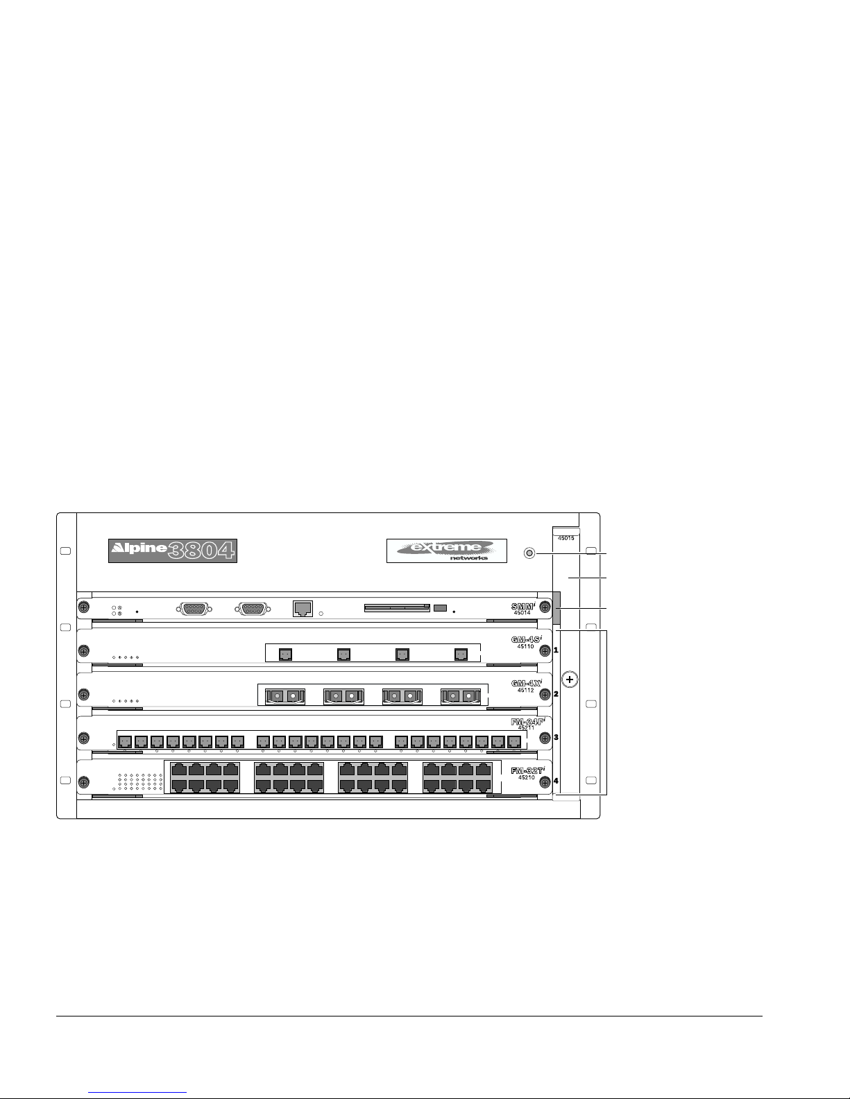
The Alpine 3804 switch, shown in Figure 1-1, consists of the following components:
• One 5-slot chassis with backplane
• Four I/O module slots, labeled Slot 1 through Slot 4
• One SMM module slot
• One or two power supplies (accessed from the rear of the unit)
• One fan tray
• One electromagnetic discharge (ESD) wrist strap receptacle
ESD
wrist strap
connector
1
17
5214
20
Figure 1-1: Alpine 3804 switch
1 234
1234
9258
24
132912
28
16
32
Fan tray
SMM
module slot
I/O module
slots
242322212019181716151413121110987654321
38_3804
1-6 Alpine 3800 Series Switch Hardware Installation Guide
 Loading...