

User's Guide
Wireless AC Circuit Identifier
Model RT32
2
Introduction
Congratulations on your purchase of Extech’s Model RT32 (869MHz) Wireless AC
Circuit Identifier. The detector can identify live circuits and detect changes in light
level with the wireless receiver. With careful use, this detector will provide years of
reliable service.
Meter Description
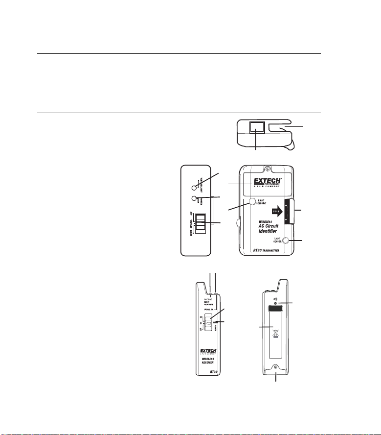
TRANSMITTER DESCRIPTION
1. Wire clamp slot
2. Wire Clamp release latch
3. Light sensor
4. Voltage/Light detect LED
5. Battery compartment
6. Power LED
7. Light setpoint button
8. Power/Mode select switch
9. External Probe Connector
RECEIVER DESCRIPTION
1. Detect LED (Amber)
2. Communication LED (Yellow)
3. Power/Mode
4. Power LED (Green)
5. Battery compartment
6. Pocket clip
7. Audio Buzzer
1 2
9
4
5
6
7
8
3
4
6
1
2
3
7
5
2
RT32-EU V2.1 4/09

Operation
Detecting Live Circuits (VOLTAGE method)
The RT32 can be directly clamped on installed building wiring
and will detect the voltage applied to the wiring.
1. Slide the transmitter power switch to the VOLTAGE
position. The POWER LED will switch on.
2. Slide the Receiver power switch to the ON position. The
POWER LED and the SIGNAL OK LED will switch ON.
3. Place the Romex
wire clamp slot or, alternatively, connect the external
voltage detector probe into the external probe socket and
then clamp the probe to any cable, extension cord or
appliance cord.
4. If the cable is “live” (voltage present), the
VOLTAGE/LIGHT amber LED on the
transmitter will switch on and the
DETECT LED on the receiver will switch
on.
5. If desired, switch the receiver power
switch to the audio OFF position
disable the audible tone.
6. When the voltage is removed (by opening the splice or the circuit breaker,
for example), the Detect LEDs will switch OFF and the detect beeper will
switch OFF.
Note: Use of the External Probe overrides the setting of the Power/Mode
Switch. The Lighting method cannot be used while the External Probe is
attached.
TM
/nm cable (AC wire) directly into the
to
3
RT32-EU V2.1 4/09

Detecting Live Circuits (LIGHTING method)
In situations where access to circuit wiring is limited,
the RT32 can also detect room lighting changes (ON
to OFF).
1. Slide the transmitter power switch to the LIGHT
position. The POWER LED will switch on.
2. Slide the Receiver power switch to the ON
position. The POWER LED will switch on.
3. Cover the Light Sensor on the transmitter and
press the Light Setpoint button.
4. Expose the Light Sensor to the light source.
The VOLTAGE/LIGHT LED on the transmitter and the DETECT LED on the
receiver will switch on
5. When the lights are turned off the VOLTAGE/LIGHT LED on the transmitter
and the DETECT LED on the receiver will switch off, indicating the light has
been switched off and power has been removed.
Note: Before use, always test the light on/off operation for proper sensitivity and
detection.
4
RT32-EU V2.1 4/09

Specifications
Indicators LED Audio Beeper, LED
Transmission
Frequency
Transmission Distance Approx. 328’ (100m) in an unobstructed field
Transmission Power +10dBm n/a
Alarm Status Visual Visual and audible
Power Supply Two (2) ‘AAA’ batteries Two (2) ‘AAA’ batteries
Battery Life 80 hours (approximately)
Operating Temperature 14 to 122°F (-10 to 50°C)
Storage Temperature -14 to 140°F (-30 to 60°C)
Operating Humidity
Storage Humidity 90% RH max.
Dimensions 4.0x2.4x1.5”
Weight 8.0 oz.(0.23 kg) – three (3) piece total
Transmitter Unit Receiver Unit
869MHz n/a
90% RH from 32-86°F (-10 to 30°C)
75% RH from 86-104°F (30 to 40°C)
45% RH from 104-122°F (40 to 50°C)
(101x61x38mm)
4.5x1.17x 1.02”
(114x30x26mm)
5
RT32-EU V2.1 4/09

Maintenance
Battery Replacement
When the Power LED begins to dim, or the transmitter and receiver stop
communicating, the batteries may need to be replaced. Each unit uses two (2)
‘AAA’ batteries (MN2400 or equivalent). The battery doors can be removed
using a Philips screwdriver to loosen the attaching screw.
You, as the end user, are legally bound (Battery ordinance) to return all
used batteries and accumulators; disposal in the household garbage is
prohibited!
You can hand over your used batteries / accumulators, gratuitously, at
the collection points for our branches in your community or wherever
Disposal
batteries / accumulators are sold!
Follow the valid legal stipulations in respect of the disposal of the
device at the end of its lifecycle
Copyright © 2008 Extech Instruments Corporation (a FLIR company)
All rights reserved including the right of reproduction in whole or in part in any form.
6
RT32-EU V2.1 4/09
 Loading...