

Page 1
User's Guide
R/C SMD Tweezers
Model RC100
Page 2
Introduction
Congratulations on your purchase of the Extech RC100
SMD Tweezers. This device offers rapid and accurate
capacitance and resistance measurements of chip
components. This meter is shipped fully tested and
calibrated and, with proper use, will provide years of
reliable service.
Precautions and Safety measures
When using this meter, the user must observe all normal
safety rules
• Allow a 30 seconds warm-up before use.
• If the meter is used near noise generating
equipment the display may become unstable or
indicate large errors.
• Do not use the meter if it appears damaged.
• Use the meter only as specified in this manual;
otherwise, the protection provided by the meter may
be impaired.
• Do not operate the meter near explosive gas, vapor,
or dust.
• To avoid damages to the instrument, do not exceed
the maximum limits of the input values.
• Caution: Don't use this device if working voltage is
above 50V DC or 36 V AC rms. Such voltages pose
a shock hazard and damage the meter
• When using this meter, keep your fingers away from
the metal of the meter.
• Before changing functions, disconnect the test clip
from the circuit under test.
• Replace the battery when the
appears. With a low battery, the meter might
produce false readings.
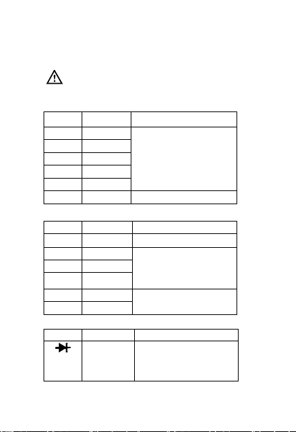
Symbols:
Symbols used in this manual and on the meter:
Caution: refer to the instruction manual.
Incorrect use may result in damage to the
device or its components.
Conforms to IEC1010
symbol
Page 3
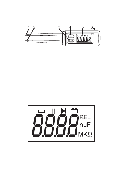
Product Description
1 Cathode “-“ input (negative)
2 Anode “+” input (positive)
3 POWER and MODE key
This key is used to power the meter and to select
the measurement function. Press the key for >4
seconds to turn power off.
4 REL key
Press this key once to enter into the Relative mode,
press again to return to the normal mode.
5 LCD display
6 Battery cover (on rear)
LCD Display
Page 4
Operation
Resistance
To avoid electrical shock or damage to
the meter, disconnect circuit power and
discharge all high-voltage capacitors
before measuring resistance.
1. Press the MODE key to select the mode.
2. Connect the test tips to the object being tested
and read the measured value on the display.
NOTE:
a. When measuring the high-resistance (> 1MΩ), it
may take a few seconds for the reading to
stabilize, this is normal.
b. When the input is not connected, i.e. an open
circuit, the "OL" (overange) icon will be
displayed.
Capacitance
To avoid electrical shock or damages to
the meter under test, disconnect circuit
power and discharge all high-voltage
capacitors before measuring capacitance.
1. Press the MODE key to select the mode.
2. Connect the test clips to the capacitor being
tested and read measured value on the display.
NOTE:
a. When measuring large valued capacitors
(200uF range), it may take up to 30 seconds for
the reading to stabilize, this is normal.
b. To improve the accuracy of measurements less
than 4nF, subtract the residual capacitance of
the meter and tips by pressing the REL key with
the tips open circuited.
Page 5

Diode measurement
To avoid electrical shock or damage to
the meter, disconnect circuit power and
discharge all high-voltage capacitors
before testing diodes.
1. Press the MODE key to select the mode.
2. Connect the + tip to the anode and the - tip to the
cathode of the diode under test.
3. The meter will show the approx. forward voltage
of the diode. If the lead connection is reversed
"OL" displayed.
Specifications
General specifications
MAX. Voltage 50V MAX between terminals and earth
Sample Rate: 3 times/sec for digital data
Display 4000 count (3 3/4 digits) LCD display
Over Range "OL" indication
Low battery
Auto power off 15 m inut es if there are no key presses
Power source (2) AG13 button cell or equivalent
Pollution degree 2
Altitude < 2000 m
Operating temp 32 to 104
Operating RH <80% RH, non-condensing
Storage temp 14 to 140
Storage RH <70% RH, battery removed
Temperature Coefficient 0.5×(specified accuracy) /
Dimensions 181(L)×35(W)×20(H) mm
Weight 65g. Approx. (battery included)
ground
°
(<18
indication
°
F (0~40 °C)
°
F (-10~60°C)
C or >28 °C)
°
C
Page 6
Range specifications
* Accuracy: ±(% of reading + number of digits) at 18
°
to 28
C (64°F to 82°F) with relative humidity to 80%.
Caution: Don't use this device if the working
voltage is above 50V DC or 36 V AC rms.
Resistance
Range Resolution Accuracy
400Ω 0.1Ω
4kΩ 1Ω
40kΩ 10Ω
400kΩ 100Ω
±(1.2% of rdg +3digits)
4MΩ 1kΩ
40MΩ 10kΩ
±(2.0% of rdg +5 digits)
Capacitance
Range Resolution Accuracy
4nF 1pF
±(5.0% of rdg +5 digits)
40nF 10pF
400nF 100pF
1nF
4µF
10nF
40µF
100nF
200µF
±(3.0% of rdg +5 digits)
±(3.0% of rdg +5 digits)
Diode Test
Range Description Test Condition
Displays
forward
voltage
drop
Forward DC Current:
approx. 1mA
Reversed DC Voltage:
approx. 1.5V
°
C
Page 7
Maintenance
General Maintenance
Periodically wipe the case with a damp cloth and mild
detergent. Do not use abrasives or solvents.
Battery replacement
Before replacing the battery, disconnect test
tips from any circuit under test
Use the following procedure:
When the battery voltage drop below proper operation
range the
and the battery need to be replaced.
Warranty
EXTECH INSTRUMENTS CORPORATION warrants the basic
instrument to be free of defects in parts and workmanship for one year
from date of shipment (a six month limited warranty applies on
sensors and cables). If it should become necessary to return the
instrument for service during or beyond the warranty period, contact
the Customer Service Department at (781) 890-7440 EXTENSION
210 for authorization or visit www.extech.com
Return Authorization (RA) number must be issued before any
product is returned to Extech. The sender is responsible for
shipping charges, freight, insurance and proper packaging to prevent
damage in transit. This warranty does not apply to defects resulting
from action of the user such as misuse, improper wiring, operation
outside of specification, improper maintenance or repair, or
unauthorized modification. Extech specifically disclaims any implied
warranties or merchantability or fitness for a specific purpose and will
not be liable for any direct, indirect, incidental or consequential
damages. Extech's total liability is limited to repair or replacement of
the product. The warranty set forth above is inclusive and no other
warranty, whether written or oral, is expressed or implied.
symbol will appear on the LCD display
1. Slide the battery cover in the direction of the
arrow to open the battery cover.
2. Replace the battery with two new 1.5V batteries
(AG13).
3. Replace the battery cover.
for more information. A
Page 8

Calibration and Repair Services
Extech offers repair and calibration services for the
products we sell. Extech also provides NIST certification
for most products. Call the Customer Service Department
for information on calibration services available for this
product. Extech recommends that annual calibrations be
performed to verify meter performance and accuracy.
Technical Support: Ext. 200; E-mail: support@extech.com
Repair & Returns: Ext. 210; E-mail: repair@extech.com
Product specifications subject to change
For the latest version of this User’s Guide and other up-to-
the-minute product information, visit our website:
Extech Instruments Corporation, 285
Support line (781) 890-7440
without notice
www.extech.com
MA 02451
Bear Hill Rd., Waltham,
RC100 V1.0 4/07
 Loading...