

Page 1
User's Guide
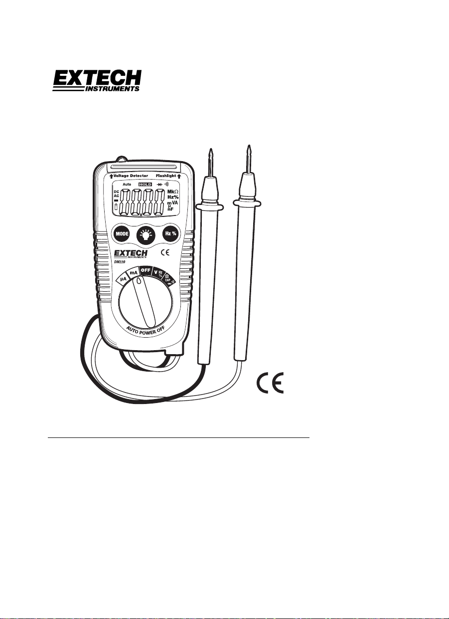
Pocket Autoranging DMM
Model DM220
AutoRanging DMM
CAT III - 1000 V
CATIV-600V
82xxx
Vr
CA V
Introduction
Congratulations on your purchase of the Extech DM220 Pocket Autoranging
Multimeter. This meter measures AC/DC Voltage, AC/DC Current with
200mA/500V resettable fuse, Resistance, Capacitance, Frequency, Duty Cycle,
Diode Test, and Continuity. It features a built-in non-contact AC voltage detector
plus flashlight. Proper use and care of this meter will provide many years of reliable
service.
Page 2
Safety
This symbol adjacent to another symbol, terminal or
operating device indicates that the operator must refer to an
explanation in the Operating Instructions to avoid personal
injury or damage to the meter.
WARNING
This meter has been designed for safe use, but must be operated with caution.
The rules listed below must be carefully followed for safe operation.
1. NEVER apply voltage or current to the meter that exceeds the specified
maximum:
V DC or V AC 600V DC/AC
µA AC/DC 200mA 500V fast acting resettable fuse
Resistance, Diode Test,
Continuity Test
2. USE EXTREME CAUTION when working with voltages greater than 25VAC
or 35VDC. These voltages are considered a shock hazard.
3. DO NOT measure voltage if the voltage on the "COM" input jack exceeds
600V above earth ground.
4. NEVER connect the meter leads across a voltage source while the function
switch is in the current, resistance, or diode mode. Doing so can damage the
meter.
5. ALWAYS discharge filter capacitors in power supplies and disconnect the
power when making resistance, continuity or diode tests.
6. ALWAYS turn off the power and disconnect the test leads from the circuit
before opening the cover to replace the batteries.
7. NEVER operate the meter unless the battery cover is in place and fastened
securely.
This WARNING symbol indicates a potentially hazardous
situation, which if not avoided, could result in death or
serious injury.
This symbol indicates that a device is protected throughout
by double insulation or reinforced insulation.
Function Maximum Input
Input Protection Limits
600V DC/AC
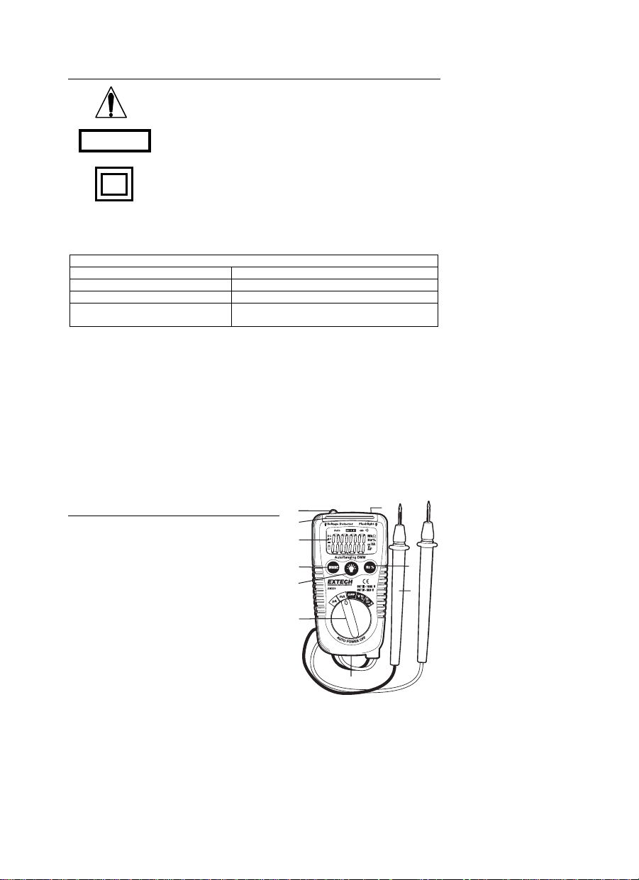
Description
1. Non-contact ACV detector probe tip
2. Non-contact ACV indicator light
3. 3-3/4 digit (4000 count) LCD
4. Mode switch
5. Flashlight button
6. Function switch
7. Battery cover
8. Test Leads
9. Hz/%Duty Cycle button
10. Flashlight
1
10
2
3
4
5
9
8
6
7
DM220 V3.0 01/06 2
Page 3
Operating Instructions
WARNING: Risk of electrocution. High-voltage circuits, both AC and DC, are very
dangerous and should be measured with great care.
1. ALWAYS turn the function switch to the OFF position when the meter is not in
use.
2. If “OL” appears in the display during a measurement, the value exceeds the
range you have selected. Change to a higher range.
NOTE: On some low AC and DC voltage ranges, with the test leads not connected
to a device, the display may show a random, changing reading. This is normal
and is caused by the high-input sensitivity. The reading will stabilize and give a
proper measurement when connected to a circuit.
AC/DC VOLTAGE MEASUREMENTS
CAUTION: Do not measure AC/DC voltages if a motor on the circuit is being
switched ON or OFF. Large voltage surges may occur that can damage the
meter.
1. Set the function switch to the V/Hz/% position.
2. Press the MODE button to indicate “AC” or “DC” on the display.
3. Touch the black test probe tip to the negative side of the circuit.
Touch the red test probe tip to the positive side of the circuit.
4. Read the voltage in the display.
AC/DC CURRENT MEASUREMENTS
1. For current measurements up to 4000µA AC/DC, set the function switch to the
µA position
2. For current measurements up to 200mA AC/DC, set the function switch to the
mA position.
3. Press the MODE button to indicate “AC” or “DC” on the display.
4. Remove power from the circuit under test, then open up the circuit at the point
where you wish to measure current.
5. Touch the black test probe tip to the negative side of the circuit.
Touch the red test probe tip to the positive side of the circuit.
6. Apply power to the circuit.
7. Read the current in the display.
RESISTANCE MEASUREMENTS
WARNING: To avoid electric shock, disconnect power to the unit under test
and discharge all capacitors before taking any resistance measurements.
Remove the batteries and unplug the line cords.
1. Set the function switch to the Ω CAP position.
2. Press the MODE button to indicate Ω on the display.
3. Touch the test probe tips across the circuit or part under test. It is best to
disconnect one side of the part under test so the rest of the circuit will not
interfere with the resistance reading.
4. Read the resistance in the display.
DM220 V3.0 01/06 3
Page 4
CONTINUITY CHECK
WARNING: To avoid electric shock, never measure continuity on circuits or
wires that have voltage on them.
1. Set the function switch to the Ω CAP position.
2. Press the MODE button to indicate on the display.
3. Touch the test probe tips to the circuit or wire you wish to check.
4. If the resistance is less than approximately 100Ω, the audible signal will sound.
If the circuit is open, the display will indicate “OL”.
DIODE TEST
1. Set the function switch to the Ω CAP position.
2. Press the MODE button to indicate on the display.
3. Touch the test probes to the diode under test. Forward voltage will typically
indicate 0.400 to 0.700V. Reverse voltage will indicate “OL”. Shorted devices
will indicate near 0V and an open device will indicate “OL” in both polarities.
CAPACITANCE MEASUREMENTS
WARNING: To avoid electric shock, disconnect power to the unit under test
and discharge all capacitors before taking any capacitance measurements.
Remove the batteries and unplug the line cords.
1. Set the rotary function switch to the Ω CAP position.
2. Press the MODE button to indicate nF on the display.
3. Touch the test leads to the capacitor to be tested.
4. Read the capacitance value in the display
FREQUENCY MEASUREMENTS
1. Set the rotary function switch to the V/Hz/% position.
2. Press the Hz /% button to indicate Hz on the display.
3. Touch the test probe tips to the circuit under test.
4. Read the frequency on the display.
% DUTY CYCLE
1. Set the rotary function switch to the V/Hz/% position.
2. Press the Hz/% button to select % on the display.
3. Touch the test probe tips to the circuit under test.
4. Read the % duty cycle on the display.
NON-CONTACT AC VOLTAGE DETECTOR
WARNING: Risk of electrocution. Before use, always test the Voltage Detector on a
known live circuit to verify proper operation.
1. The Voltage Detector works in any function switch position, including OFF.
2. Place the detector probe tip next to the hot conductor or insert into the hot side
of the electrical outlet.
3. If AC voltage is present, the detector light will illuminate.
NOTE: The conductors in electrical cord sets are often twisted. For best results,
rub the probe tip along a length of the cord to assure placing the tip in
close proximity to the live conductor.
NOTE: The detector is designed with high sensitivity. Static electricity or other
sources of energy may randomly trip the sensor. This is normal
operation.
DM220 V3.0 01/06 4
Page 5
FLASHLIGHT
Press and hold the
the flashlight off.
button to turn the flashlight on. Release the button to turn
AUTO POWER OFF
The auto off feature will turn the meter off after 15 minutes.
LOW BATTERY INDICATION
The icon will appear in the lower left corner of the display when the battery
voltage becomes low. Replace the battery when this appears.
Maintenance
WARNING: To avoid electric shock, disconnect the test leads from any source
of voltage before removing the battery cover.
WARNING: To avoid electric shock, do not operate your meter until the battery
cover is in place and fastened securely.
This MultiMeter is designed to provide years of dependable service, if the following
guidelines are followed:
1. KEEP THE METER DRY. If it gets wet, wipe it off.
2. USE AND STORE THE METER IN NORMAL TEMPERATURES. Temperature
extremes can shorten the life of the electronic parts and distort or melt plastic
parts.
3. HANDLE THE METER GENTLY AND CAREFULLY. Dropping it can damage
the electronic parts or the case.
4. KEEP THE METER CLEAN. Wipe the case occasionally with a damp cloth.
DO NOT use chemicals, cleaning solvents, or detergents.
5. USE ONLY FRESH BATTERIES OF THE RECOMMENDED SIZE AND TYPE.
Remove old or weak batteries so they do not leak and damage the unit.
6. IF THE METER IS TO BE STORED FOR A LONG PERIOD OF TIME, the
batteries should be removed to prevent damage to the unit.
BATTERY INSTALLATION
WARNING: To avoid electric shock, disconnect the test leads from any source of
voltage before removing the battery cover.
1. Turn power off.
2. Open the rear battery cover by removing the Phillips head screw located on the
bottom of the meter.
3. Insert the batteries into battery holder, observing the correct polarity.
4. Put the battery cover back in place. Secure with the screw.
WARNING: To avoid electric shock, do not operate the meter until the battery
cover is in place and fastened securely.
NOTE: If your meter does not work properly, check the batteries to make sure that
they are still good and that they are properly inserted.
RESETTABLE FUSE
1. The fast acting, 0.2A/500V resettable fuse will open if the current limits of the
meter are exceeded.
2. The fuse will automatically reset itself when the suspect current is removed
from the meter’s input.
DM220 V3.0 01/06 5
Page 6

Specifications
Function Range Resolution Accuracy
DC Voltage
AC Voltage
DC Current
AC Current
Resistance
apacitance
Frequency
Duty Cycle 0.5 to 99% 0.5%
NOTE: Accuracy specifications consist of two elements:
• (% reading) – This is the accuracy of the measurement circuit.
• (+ digits) – This is the accuracy of the analog to digital converter.
NOTE: Accuracy is stated at 65
400mV 0.1mV
4V 0.001V
40V 0.01V
400V 0.1V
600V 1V
50 to 60Hz
4V 1mV
40V 0.01V
400V 0.1V
600V 1V
400µA 0.1µA
4000µA 1µA
40mA 0.01mA
200mA 0.1mA
50 to 60Hz
400µA 0.1µA
4000µA 1µA
40mA 0.01mA
200mA 0.1mA
400Ω 0.1Ω ±(0.8% reading + 5 digits)
4kΩ 0.001kΩ ±(1.2% reading + 5 digits)
40kΩ 0.01kΩ
400kΩ 0.1kΩ
4MΩ 0.001MΩ ±(3.0% reading + 5digits)
40MΩ 0.01MΩ ±(5.0% reading + 5digits)
4nF 0.001nF
40nF 0.01nF
400nF
4µF 0.001µF
40µF 0.01µF
200µF 0.1µF
9.999Hz 0.001Hz
99.999Hz 0.001Hz
999.9Hz 0.1Hz
9.999kHz 0.001kHz
0.1nF
o
F to 83oF (18oC to 28oC) and less than 75% RH.
±(0.8% reading + 2 digits)
±(1.0% reading + 2 digits)
±(1.0% reading + 5 digits)
±(1.5% reading + 5 digits)
±(2.0% reading + 2 digits)
±(2.5% reading + 5 digits)
±(0.8% reading + 2 digits)
±(5.0% reading + 0.6nF)
±(3.5% reading + 30 digits)
±(3.0% reading + 20 digits)
±(5.0% reading + 30 digits)
±(1.0% reading + 2 digits)
±(2.0% reading + 5 digits)
DM220 V3.0 01/06 6
Page 7

Diode Test Test current 1mA, open circuit voltage 1.5V DC typical
Continuity Check Audible sound if the resistance is less than 100Ω
Non-Contact Volt detect 100 to 600VAC; 50/60Hz
Input Impedance >7.5MΩ (VDC & VAC)
AC Response Average responding
ACV Bandwidth 50Hz to 60Hz
Display 4000 count 3-3/4 digit liquid crystal
Overrange indication “OL” is displayed
Polarity Automatic (no indication for positive); Minus (-) sign for
negative
Auto Power Off 15 minutes (approx)
Low Battery Indication “ ” is displayed if battery voltage drops below operating
voltage
Batteries Two 1.5 volt AAA
Fuses mA, µA ranges; 0.2A/500V fast acting resettable fuse
Operating Temperature 32ºF to 104ºF (0ºC to 40ºC)
Storage Temperature 14
o
F to 122oF (-10oC to 50oC)
Operating Humidity Max 80% up to 87ºF (31ºC) decreasing linearly to 50% at
104ºF (40ºC)
Storage Humidity <80%
Operating Altitude 7000ft. (2000meters) maximum.
Weight 0.319lb (145g)
Size 4.09” x 2.1” x 1.2” (104 x 55 x 32.5mm)
Safety For origin of installation use and in accordance with the
requirements for double insulation per EN61010-1 and
IEC61010-1 2
nd
Edition (2001) to Overvoltage Category IV
600V and Category III 1000V; Pollution Degree 2.
Warranty
EXTECH INSTRUMENTS CORPORATION warrants this instrument to be free of defects in parts
and workmanship for three years from date of shipment (a six month limited warranty applies to
sensors and cables). If it should become necessary to return the instrument for service during or
beyond the warranty period, contact the Customer Service Department at (781) 890-7440 ext. 210
for authorization or visit our website www.extech.com for contact information. A Return
Authorization (RA) number must be issued before any product is returned to Extech. The sender is
responsible for shipping charges, freight, insurance and proper packaging to prevent damage in
transit. This warranty does not apply to defects resulting from action of the user such as misuse,
improper wiring, operation outside of specification, improper maintenance or repair, or
unauthorized modification. Extech specifically disclaims any implied warranties or merchantability
or fitness for a specific purpose and will not be liable for any direct, indirect, incidental or
consequential damages. Extech's total liability is limited to repair or replacement of the product .
The warranty set forth above is inclusive and no other warranty, whether written or oral, is
expressed or implied.
Technical support: Extension 200; E-mail: support@extech.com
Repair & Returns: Extension 210; E-mail: repair@extech.com
Product specifications subject to change without notice
For up-to-the-minute product information, visit our website: www.extech.com
Extech Instruments Corporation, 285 Bear Hill Rd., Waltham, MA 02451
Copyright © 2006 Extech Instruments Corporation
All rights reserved including the right of reproduction in whole or in part in any form.
Support line (781) 890-7440
DM220 V3.0 01/06 7
Page 8

DM220 V3.0 01/06 8
Page 9

Manual del usuario
MMD de bolsillo con escala automática
Modelo DM220
AutoRanging DMM
CAT III - 1000 V
CATIV-600V
Vr
82xxx
CA V
Introducción
Agradecemos su compra del multímetro de escala automática modelo DM220 de
Extech. Este medidor lee voltaje CA/CD, corriente CA/CD con fusible de reposición
de 200mA/500V, resistencia, capacitancia, frecuencia, ciclo de trabajo, prueba de
diodo y continuidad. Ofrece un detector integrado de voltaje CA sin contacto, más
linterna. El uso y cuidado apropiado de este medidor le proveerá muchos años de
servicio confiable.
DM220 V3.0 01/06 9
Page 10

Seguridad
Esta señal adyacente a otra señal, terminal o dispositivo en
operación indica que el usuario deberá buscar la
explicación en las Instrucciones de operación para evitar
lesiones a su persona o daños al medidor.
ADVERTEN
Este medidor ha sido diseñado para uso seguro, sin embargo debe ser operado
con precaución. Para operar con seguridad deberá cumplir las reglas
enumeradas a continuación.
1. NUNCA aplique al medidor voltaje o corriente que exceda los límites
máximos especificados:
V CD o V CA 600V CD/CA
µA CA/CD 200mA 500V fusible de acción rápida de
Resistencia, prueba de diodo,
prueba de continuidad
2. EXTREME SUS PRECAUCIONES al trabajar con voltajes mayores a 25VCA
o 35VDC. Estos voltajes son considerados un peligro de choque.
3. NO mida voltajes si el voltaje en el enchufe de entrada "COM" excede 600V
sobre tierra física.
4. NUNCA conecte los cables del medidor a una fuente de voltaje cuando el
selector de función esté en modo de corriente, resistencia o diodo. Hacerlo
puede dañar al medidor.
5. SIEMPRE descargue los filtros capacitores en las fuentes de tensión y
desconecte la energía al realizar pruebas de diodo o de resistencia.
6. SIEMPRE apague la tensión y desconecte los cables de prueba antes de
abrir la tapa para reemplazar las baterías o fusibles.
7. NUNCA opere el medidor a menos que la tapa posterior y la tapa de la
batería y fusibles estén colocadas y aseguradas.
Descripción
1. Punta del detector de V-CA sin contacto
2. Luz indicadora de VCA sin contacto
3. LCD 3-3/4 dígitos (4000 cuentas)
4. Interruptor de modo
5. Botón para linterna
6. Selector de función
7. Tapa de baterías
8. Cables de prueba
9. Botón Hz/% Ciclo de trabajo
10. Linterna
Esta señal de ADVERTENCIA indica que existe una
situación potencialmente peligrosa, que si no se evita,
podría resultar en la muerte o lesiones graves.
Esta señal indica que un dispositivo está completamente
protegido mediante doble aislante o aislamiento reforzado.
Límites de protección de alimentación
Función Entrada máxima
reposición
600V CD/CA
1
10
2
3
4
5
9
8
6
7
DM220 V3.0 01/06 10
Page 11

Instrucciones de operación
ADVERTENCIA: Riesgo de electrocución. Los circuitos de alta tensión, tanto de
CA y CD, son muy peligrosos y deberán ser medidos con gran cuidado.
1. SIEMPRE gire el conmutador de función a la posición de apagado
(OFF) cuando el medidor no esté en uso.
2. Si en la pantalla aparece "OL" durante una medida, el valor excede la
escala que ha seleccionado. Cambie a una escala más alta.
NOTA: En algunas escalas bajas de voltaje CA y CD, sin estar los cables de
prueba conectados a dispositivo alguno, la pantalla puede mostrar una lectura
aleatoria cambiante. Esto es normal y es causado por la alta sensibilidad de la
alimentación. La lectura se estabilizará y dará una medida apropiada al estar
conectada a un circuito.
MEDICIÓN DE VOLTAJE CA/CD
PRECAUCIÓN: No mida voltajes CA/CD si algún motor en el circuito está
encendiendo y apagando. Pueden ocurrir grandes oleadas de voltaje que
dañarían al medidor.
1. Fije el selector de función en la posición V/Hz/%.
2. Presione el botón MODE para indicar “CA” o “CD” en la pantalla.
3. Toque la punta de la sonda negra de prueba del lado negativo del circuito.
Toque la punta de la sonda roja de prueba del lado positivo del circuito.
4. Lea el voltaje en la pantalla.
MEDICIÓN DE CORRIENTE CD/CA
1. Para medidas de corriente hasta 4000µA CA/CD, fije el selector de
función en la posición µA
2. Para medidas de corriente hasta 200mA CA/CD, fije el selector de función
en la posición mA.
3. Presione el botón MODE para indicar “CA” o “CD” en la pantalla.
4. Corte la tensión del circuito bajo prueba, enseguida abra el circuito en el
punto donde desea medir la corriente.
5. Toque la punta de la sonda negra de prueba del lado negativo del circuito.
Toque la punta de la sonda roja de prueba del lado positivo del circuito.
6. Aplique tensión al circuito.
7. Lea la corriente en la pantalla.
MEDIDAS DE RESISTENCIA
ADVERTENCIA: Para evitar choque eléctrico, desconecte la tensión a la
unidad bajo prueba y descargue todos los capacitores antes de tomar
cualquier medida de resistencia. Retire las baterías y desconecte los
cordones de línea.
1. Fije el selector de función en la posición Ω CAP .
2. Presione el botón MODE para indicar Ω en la pantalla.
3. Toque las puntas de las sondas a través del circuito o parte bajo prueba.
Es mejor desconectar un lado de la pieza bajo prueba para que el resto
del circuito no interfiera con la lectura de resistencia.
4. Lea la resistencia en la pantalla.
DM220 V3.0 01/06 11
Page 12

VERIFICACIÓN DE CONTINUIDAD
ADVERTENCIA: Para evitar choque eléctrico, nunca mida continuidad en
circuitos o alambres que tengan voltaje.
1. Fije el selector de función en la posición Ω CAP .
2. Presione el botón MODE para indicar en la pantalla.
3. Toque las puntas de las sondas al circuito o alambre que desee probar.
4. Si la resistencia es menor a aproximadamente 100Ω, sonará una señal
audible. Si el circuito está abierto, la pantalla indicará “OL”.
PRUEBA DE DIODO
1. Fije el selector de función en la Ω CAP .
2. Presione el botón MODE para indica en la pantalla.
3. Toque las puntas de las sondas al diodo bajo prueba. El voltaje directo
indicará típicamente 0.400 a 0.700 V. El voltaje inverso indicará "OL”. Los
dispositivos en corto indicarán cerca de 0V y un dispositivo abierto indicará
"OL" en ambas polaridades.
MEDICIÓN DE CAPACITANCIA
ADVERTENCIA: Para evitar choque eléctrico, desconecte la tensión a la
unidad bajo prueba y descargue todos los capacitores antes de tomar medidas
de capacitancia. Retire las baterías y desconecte los cordones de línea.
1. Fije el selector de función en la posición Ω CAP .
2. Presione el botón MODE para indicar nF en la pantalla.
3. Toque las puntas de las sondas a través del capacitor a probar.
4. Lea el valor de capacitancia en la pantalla
MEDIDAS DE FRECUENCIA
1. Fije el selector giratorio de función en la posiciónV/Hz/%.
2. Presione el botón Hz/% para indicar Hz en la pantalla.
3. Toque las puntas de las sondas a través del circuito bajo prueba.
4. Lea la frecuencia en la pantalla.
% CICLO DE TRABAJO
1. Fije el selector giratorio de función en la posición V/Hz/%.
2. Presione el botón Hz/% para seleccionar % en la pantalla.
3. Toque las puntas de las sondas a través del circuito bajo prueba.
4. Lea el % de ciclo de trabajo en la pantalla.
DETECTOR DE VOLTAJE CA SIN CONTACTO
ADVERTENCIA: Riesgo de electrocución. Antes de usar, pruebe siempre el
detector de voltaje en un circuito vivo para verificar el funcionamiento correcto.
1. El detector de voltaje funciona en cualquier posición del interruptor/selector de
funciones, incluyendo OFF (apagado).
2. Coloque la punta del detector junto al conductor caliente o inserte del lado de
la corriente en un enchufe de pared.
3. Si hay voltaje CA, la luz del detector se encenderá.
NOTA: A menudo los conductores de los cordones eléctricos están torcidos. Para
obtener mejores resultados, frote la punta de la sonda a lo largo del cordón
para asegurar que se coloca la punta en cercanía al conductor vivo.
NOTA: El detector está diseñado con alta sensibilidad. Algunas fuentes de
electricidad estática u otras fuentes de energía pueden disparar el sensor en
cualquier momento. Es normal en operación.
DM220 V3.0 01/06 12
Page 13

LINTERNA
Presione y sostenga el botón
para encender la linterna. Suelte el botón para
apagar la linterna.
APAGADO AUTOMÁTICO
La función de Apagado automático apagará el medidor después de 15 minutos.
BATERÍA DÉBIL
El icono aparecerá en la esquina inferior izquierda de la pantalla cuando baje el
voltaje de la batería. Reemplace la batería cuando éste se presente.
Mantenimiento
ADVERTENCIA: Para evitar choque eléctrico, desconecte los cables de prueba
de cualquier fuente de voltaje antes de quitar la tapa de la batería.
ADVERTENCIA: Para evitar choque eléctrico, no opere el medidor a menos
que la tapa de la batería y fusibles estén colocadas y aseguradas.
Este multímetro está diseñado para proveer muchos años de servicio confiable, si
se llevan a cabo las siguientes instrucciones de cuidado:
1. MANTENGA SECO EL MEDIDOR. Si se moja, séquelo.
2. USE Y ALMACENE EL MEDIDOR BAJO TEMPERATURA NORMAL. Los
extremos de temperatura pueden acortar la vida de las partes electrónicas y
distorsionar o fundir las piezas de plástico.
3. MANIPULE EL MEDIDOR CON SUAVIDAD Y CUIDADO. Dejarlo caer
puede dañar las partes electrónicas o la caja.
4. MANTENGA LIMPIO EL MEDIDOR. Ocasionalmente limpie la caja con un
paño húmedo. NO use químicos, solventes para limpieza o detergentes.
5. USE SÓLO BATERÍAS NUEVAS DEL TAMAÑO Y TIPO RECOMENDADO.
Retire las baterías viejas o débiles de manera que no se derramen y dañen la
unidad.
6. SI SE VA A ALMACENAR EL MEDIDOR DURANTE UN LARGO PERIODO
DE TIEMPO, deberá retirar la batería para prevenir daños a la unidad.
Instalación de la batería
ADVERTENCIA: Para evitar choque eléctrico, desconecte los cables de prueba
de cualquier fuente de voltaje antes de quitar la tapa de la batería.
1. Apague.
2. Para abrir la tapa de la batería quite el tornillo cabeza Phillips de la parte baja
del medidor.
3. Inserte las baterías en el soporte, observando la polaridad correcta.
4. Coloque la tapa de la batería en su lugar. Asegure con el tornillo.
ADVERTENCIA: Para evitar choque eléctrico, no opere el medidor a menos
que la tapa posterior y la tapa de la batería y fusibles estén colocadas y
aseguradas.
NOTA: Si su medidor no funciona correctamente, revise los fusibles y la batería
para asegurar que están en buenas condiciones y correctamente
instalados.
FUSIBLE DE REPOSICIÓN
1. El fusible de reposición de acción rápida de 0.2A/500V se abrirá si se
exceden los límites de corriente del medidor.
2. El fusible automáticamente se repondrá al terminar la corriente excedente.
DM220 V3.0 01/06 13
Page 14

Especificaciones
Función Escala Resolución Precisión
Voltaje CD
Voltaje CA
Corriente
CD
Corriente
CA
Resistencia
apacitancia
Frecuencia
Ciclo de
trabajo
NOTA: Las especificaciones de precisión consisten de dos elementos:
• (% de lectura) - Esta es la precisión del circuito de medidas.
• (+ dígitos) - Esta es la precisión del convertidor analógico a digital.
NOTA: La precisión está especificada a 18o
400 mV 0.1mV
4 V 0.001V
40V 0.01V
400V 0.1V
600V 1V
50 a 60 Hz
4 V 1mV
40V 0.01V
400V 0.1V
600V 1V
400µA 0.1µA
4000µA 1µA
40 mA 0.01mA
200mA 0.1mA
50 a 60 Hz
400µA 0.1µA
4000µA 1µA
40 mA 0.01mA
200mA 0.1mA
400Ω 0.1Ω ±(0.8% lectura + 5 dígitos)
4 kΩ 0.001kΩ ±(1.2% lectura + 5 dígitos)
40kΩ 0.01kΩ
400kΩ 0.1kΩ
4 MΩ 0.001MΩ ±(3.0% lectura + 5 dígitos)
40MΩ 0.01MΩ ±(5.0% lectura + 5 dígitos)
4 nF 0.001nF
40nF 0.01nF
40nF
4µF 0.001µF
40µF 0.01µF
200µF 0.1µF
9.999Hz 0.001Hz
99.999Hz 0.001Hz
999.9Hz 0.1Hz
9.999kHz 0.001kHz
0.5 a 99% 0.5%
0.1nF
±(0.8% lectura + 2 dígitos)
±(1.0% lectura + 2 dígitos)
±(1.0% lectura + 5 dígitos)
±(1.5% lectura + 5 dígitos)
±(2.0% lectura + 2 dígitos)
±(2.5% lectura + 5 dígitos)
±(0.8% lectura + 5 dígitos)
±(5.0% lectura + 0.6 nF)
±(3.5% lectura + 30 dígitos)
±(3.0% lectura + 20dígitos)
±(5.0% lectura + 30 dígitos)
±(1.0% lectura + 2 dígitos)
±(2.0% lectura + 5 dígitos)
C a 28oC (65oF a 83
oF) y menor a 75% RH.
DM220 V3.0 01/06 14
Page 15

Prueba de diodo Corriente de prueba 1mA, voltaje típico de circuito abierto
Verificación de
continuidad
Detección de voltaje sin
contacto
Impedancia de entrada >7.5MΩ (VCD y VCA)
Respuesta CA Respuesta promedio
Amplitud de banda VCA 50Hz a 60Hz
Pantalla 4000 cuentas, 3-3/4 dígitos, cristal líquido
Indicación de fuera de
escala
Polaridad Automática (sin indicación para positivo); Signo de menos (-)
Apagado automático 15 minutos (aprox)
Indicación de batería
débil
Baterías Dos AAA de 1.5 voltios
Fusibles escalas mA, µA; 0.2A/500V fusible de acción rápida de
Temperatura de
operación
Temperatura de
almacenamiento
Humedad de operación Máx 80% hasta 31ºC (87ºF) con disminución linear hasta
Humedad de
almacenamiento
Altitud de operación 7000ft. (2000 metros) máxima
Peso 145g (0.319lb)
Tamaño 104 x 55 x 32.5mm (4.09” x 2.1” x 1.2”)
Seguridad Este medidor está diseñado para uso en interiores y con
1.5V CD
Sonido audible si la resistencia es menor a 100Ω
100 a 600 VCA; 50/60Hz
indica “OL”
para negativo
“ ” si el voltaje de la batería cae por debajo del voltaje de
operación
reposición
0ºC a 40ºC (32ºF a 104ºF)
-10oC a 50oC (14 oF a 122oF)
50% a 40ºC (104ºF)
<80%
protección para usuarios por doble aislante como
especifican las normas EN61010-1 y IEC61010-1, 2°
Edición (2001) y CAT II 600V y Cat III 1000V; Grado de
contaminación 2
Garantía
EXTECH INSTRUMENTS CORPORATION garantiza ese instrumento libre de defectos en partes y mano de obra
durante tres años a partir de la fecha de embarque (se aplica una garantía limitada de seis meses a cables y
sensores). Si fuera necesario regresar el instrumento para servicio durante o después del periodo de garantía,
llame al Departamento de Servicio a Clientes al teléfono (781) 890-7440 ext. 210 para autorización o visite
nuestra página en Internet en www.extech.com para Información de contacto. Se debe otorgar un número de
Autorización de Retorno (RA) antes de regresar cualquier producto a Extech. El remitente es responsable de los
gastos de embarque, flete, seguro y empaque apropiado para prevenir daños en tránsito. Esta garantía no se
aplica a defectos que resulten por acciones del usuario como mal uso, alambrado inapropiado, operación fuera de
las especificaciones, mantenimiento o reparaciones inapropiadas o modificaciones no autorizadas. Extech
específicamente rechaza cualesquier garantías implícitas o factibilidad de comercialización o aptitud para
cualquier propósito determinado y no será responsable por cualesquier daños directos, indirectos, incidentales o
consecuentes. La responsabilidad total de Extech está limitada a la reparación o reemplazo del producto. La
garantía precedente es inclusiva y no hay otra garantía ya sea escrita u oral, expresa o implícita.
Soporte Técnico Extensión 200; Correo electrónico: support@extech.com
Línea de soporte (781) 890-7440
Reparación / Retornos: Extensión 210; Correo electrónico: repair@extech.com
Las especificaciones del producto están sujetas a cambios sin aviso
Para información al día de este producto, visite nuestra página en Internet: www.extech.com
Extech Instruments Corporation, 285 Bear Hill Rd., Waltham, MA 02451
Reservados todos los derechos, incluyendo el derecho de reproducción total o parcial en
Copyright © 2006 Extech Instruments Corporation
cualquier medio.
DM220 V3.0 01/06 15
 Loading...