

Page 1
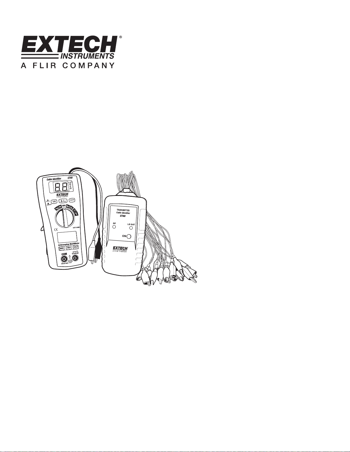
User's Guide
Cable Tester and Digital
Multimeter
Model CT40
Page 2
Introduction
Congratulations on your purchase of the Extech CT40. This meter is shipped fully tested
and calibrated and, with proper use, will provide years of reliable service.
cable tester which uses a transmitter/receiver to allow for wire identification of an individual
core to the end of a multi-core cable .The meter’s digital multimeter functions provides for
easy measurement of AC/DC Voltage, AC/DC Current, Resistance, Continuity and Diode
check.
The CT40 is a
Safety
International Safety Symbols
This symbol, adjacent to another symbol or terminal, indicates the user must refer
to the manual for further information.
This symbol, adjacent to a terminal, indicates that, under normal use, hazardous
voltages may be present
Safety Notes
Warnings
Double insulation
• Do not exceed the maximum allowable input range of any function.
• Set the function switch OFF when the meter is not in use.
• Remove the battery if meter is to be stored for longer than 60 days.
• Set function switch to the appropriate position before measuring.
• Do not measure current on a circuit whose voltage exceeds 600V.
• When changing ranges always disconnect the test leads from the circuit under test.
Cautions
• Improper use of this meter can cause damage, shock, injury or death. Read and
understand this user manual before operating the meter.
• Always remove the test leads before replacing the battery.
• Inspect the condition of the test leads and the meter itself for any damage before
operating the meter. Repair or replace any damage before use.
• Use great care when making measurements if the voltages are greater than 25VAC
rms or 35VDC. These voltages are considered a shock hazard.
• Voltage checks on electrical outlets can be difficult and misleading because of the
uncertainty of connection to the recessed electrical contacts. Other means should be
used to ensure that the terminals are not "live".
• If the equipment is used in a manner not specified by the manufacturer, the protection
provided by the equipment may be impaired.
2
CT40 V1.3 09/09
Page 3
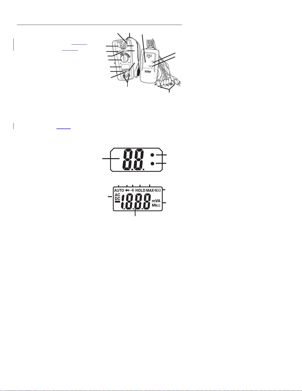
Meter Description
1. Low Battery Indicator -Receiver
2. Receiver Alligator Test Leads
3. Operation Indicator -Receiver
4. On/Off Switch -Receiver
5. Hold Switch – Digital Multimeter Mode
6. DMM Input Jacks
7. Max Button – Digital Multimeter Mode
8. Mode Button – Digital Multimeter Mode
9. LCD Display – Multimeter Mode
10. Rotary Switch – Multimeter Mode
11. ID Test Button –Continuity Beep Test
12. V Check Button – Cable Voltage Check
13. LCD Display for Cable Identifier Function
14. Operation Indicator- Transmitter
15. Low Battery Indicator –Transmitter
16. On/Off Switch – Transmitter
17. Transmitter Alligator
Test Leads – CH1-16
LCD display descriptions
1. Cable ID Number Display
2. Low bat LED
3. OP operation LED
4. Autorange Indicator
5. Diode Test
6. Continuity
7. Display Hold
8. Max
9. Low Battery Indicator
10. Units
11. DMM Digit Display
12. AC/DC Indicators
2
1
13
12
11
10
9
8
7
1
14
3
4
5
6
LO BAT
15
16
17
2
OP
3
7
5
6
4
8
9
12
10
11
3
CT40 V1.3 09/09
Page 4

Operation
Transmitter and Receiver Cable Tester Operation
1. Press down the receiver’s ON/OFF switch. The upper blue display will indicate “00”
and the OP LED should light.
2. Press down the transmitter’s ON switch. The OP LED will flash.
3. Connect one of the transmitter’s alligator clips (CH1 to CH16) to each core (wire) of
the cable under test.
4. Connect the transmitter’s “COM” reference lead (black alligator) to a known common
for all cables, such as ground or cable sheath.
5. Connect the receiver’s “COM terminal” (black alligator) to the common.
6. Touch the receiver’s “input terminal” (red alligator) test lead to one core of the cable
under test.
7. The number of the wire selected is indicated on the display of the receiver (1-16).
CAUTION: Do not apply over 50V (AC or DCV) to
This could result in permanent damage to the meter.
Continuity Beep Test
1. Press the ID TEST button down.
2. Connect the receiver’s red and black alligator clips to each end of a wire.
3. If there is continuity (resistance is less than the continuity threshold) there will be an
audible tone.
Voltage Check
test leads of transmitter or receiver.
1. Press the V check button down.
2. Connect both of the receiver’s alligator clips to each end of the cable under test.
3. If the display indicates “UU” then voltage is present on the cable. Locate and remove
the voltage source before proceeding with cable testing.
4
CT40 V1.3 09/09
Page 5

Digital Multimeter Functions
AC/DC Voltage Measurements
1. Insert the black test lead into the negative COM terminal and the red test lead into the
positive V terminal.
2. Set the rotary function switch to VAC or VDC position.
3. Connect the test leads in parallel to the circuit under test.
4. Read the voltage measurement on the LCD display.
CAUTION: Do not measure AC/ DC voltages if a motor on the circuit is being switched
ON or OFF. Large voltage surges may occur that can damage the meter.
AC/DC Current Measurements
1. Set the function switch to the µA/mA position.
2. Insert the black test lead into the negative COM terminal and the red test lead into the
positive µA/mA terminal.
3. For current measurements up to 2000µA DC/AC, set the function switch to the mA
position
4. Press the MODE button to indicate “DC” / “AC” on the display.
5. Connect the meter in series with the circuit under test, the black test probe tip to the
negative side of the circuit and the red test probe tip to the positive side of the circuit.
6. Apply power to the circuit.
7. Read the current in the display
Resistance Measurements
1. Set the function switch to the Ω position.
2. Insert the black test lead into the negative COM terminal and the red test lead into the
positive Ω terminal.
3. Touch the test probe tips across the circuit or part under test. It is best to disconnect
one side of the part under test so the rest of the circuit will not interfere with the
resistance reading.
4. Read the resistance in the display
WARNING: To avoid electric shock, disconnect power to the unit under test and
discharge all capacitors before taking any resistance measurements.
5
CT40 V1.3 09/09
Page 6

Continuity Check
WARNING: To avoid electric shock, never measure continuity on circuits or wires that
have voltage on them.
1. Set the function switch to the position.
2. Insert the black lead banana plug into the negative (-) jack (COM) and the red test
lead banana plug into the positive (+) jack (Ω).
3. Press the MODE button until the symbol appears in the display.
4. Touch the test probe tips to the circuit or wire you wish to check.
5. If the resistance is less than the continuity threshold, the audible signal will sound.
The display will also show the actual resistance.
DIODE TEST
WARNING: To avoid electric shock, do not test any diode that has voltage on it.
1. Set the function switch to position.
2. Press the MODE button until the symbol
appears in the display.
3. Insert the black test lead banana plug into the negative (-) jack (COM) and the red
test lead banana plug into the positive (+) jack (Ω).
4. Touch the test probe tips to the diode or semiconductor junction you wish to test. Note
the meter reading.
5. Reverse the probe polarity by switching probe position. Note this reading.
6. The diode or junction can be evaluated as follows:
A. If one reading shows a value and the other reading shows OL, the diode is good.
B. If both readings show OL, the device is open.
C. If both readings are very small or 0, the device is shorted.
NOTE: The value indicated in the display during the diode check is the forward voltage.
MAX Hold Function
1. Press the MAX Hold Button. The meter
continues taking measurements but the
display shows only the highest (MAX) reading recorded.
2. Press the Max Hold Button again to return to normal operation.
Data Hold Function
1. Press the Data Hold Button. The HOLD indicator will appear. The hold function
freezes the reading in the display.
2. Press the Data Hold Button again to return to normal operation.
Auto Power OFF Function
The auto off feature will turn the meter off after 15 minutes.
6
CT40 V1.3 09/09
Page 7

Maintenance
REPLACING THE FUSES
WARNING: To avoid electric shock, disconnect the test leads from any source of voltage
before removing the fuse cover.
1. Disconnect the test leads from the meter.
2. Remove the battery cover (two “B” screws) and the battery.
3. Remove the four “A” screws securing the rear cover.
4. Lift the center circuit board straight up from the connectors to gain access to the fuse
holders
5. Gently remove the old fuse and install the new fuse into the holder.
6. Always use a fuse of the proper size and value (0.2A/250V fast blow for the 200mA
range).Replace and secure the rear cover, battery and battery cover.
7. Align the center board with the connectors and gently press into place.
8. Replace and secure the rear cover, battery and battery cover.
WARNING: To avoid electric shock, do not operate your meter until the fuse cover is in
place and fastened securely.
BATTERY INSTALLATION
WARNING: To avoid electric shock, disconnect the test leads from any source of voltage
before removing the battery cover.
1. When the “Low Battery Indicator” is lit on the Transmitter or the Receiver it is
necessary to replace the battery.
2. Turn power off and disconnect the test leads from the meter.
3. Open the rear battery cover by removing the screw.
4. Insert the battery into battery holder, observing the correct polarity.
5. Put the battery cover back in place. Secure with the screw.
WARNING: To avoid electric shock, do not operate the meter until the battery cover is in
place and fastened securely.
Calibration and Repair Services
Extech offers repair and calibration services for the products we sell. Extech also
provides NIST certification for most products. Call the Customer Care Department for
information on calibration services available for this product. Extech recommends that
annual calibrations be performed to verify meter performance and accuracy.
Technical Support: Extension 200; E-mail: support@extech.com
Repair & Returns: Extension 210; E-mail: repair@extech.com
Product specifications subject to change without notice
For the latest version of this User Guide, Software updates, and other
up-to-the-minute product information, visit our website: www.extech.com
Extech Instruments Corporation, 285 Bear Hill Road, Waltham, MA 02451
Support line (781) 890-7440
7
CT40 V1.3 09/09
Page 8

Specifications
Max input voltage 600V AC/DC
Diode Test Test current 1mA max., open circuit voltage of 1.5V
Continuity Check Audible threshold between 15Ω and 200Ω
Display 2000 count 3 -1/2 digit LCD
Over range indication LCD displays “OL”
Polarity Minus (-) sign for negative polarity.
Low Battery Indication “BAT” symbol indicates low battery condition.
Input Impedance >7.5MΩ (VDC & VAC)
AC Response Average responding
ACV Bandwidth 50Hz to60Hz
Auto Power Off 15 minutes (approximately)
Fuse mA, µA ranges; 0.2A/250V fast
Batteries 9V battery and two “AAA” batteries
Operating Temperature 32°F to 104°F (0°C to 40°C)
Storage Temperature 14°F to 122°F (-10°C to 50°C)
Weight 10.8 oz (308g)
Size 6.3x2.9x1.7”, (162x74.5x44.0mm)
Standards IEC61010-1 CAT III-600V Pollution degree II, CE
Transmitter Specifications
Display Two red LED lamps
Alligators 17Croc clips-red*16, black*1
Cable resistance 30K Ohm max
Power 9V battery
Power current 1.8mA
Operating temperature 0°C to 40°C (32°F to 104°f)
Storage temperature –10°C to 50°C (14F to 122°F)
Receiver Specifications
Display Two digit blue LED display
Alligators 2 Croc clips-red*1, black*1
Power 9V battery
Power current 23mA
Operating temperature 0°C to 40°C (32°F to 104°F)
Storage temperature –10°C to 50°C (14°F to 122°F)
Continuity test Audible threshold between 15Ω and 1000Ω
Cable voltage check 5V to 16V DC
typical
acting Fuse
Approved
8
CT40 V1.3 09/09
Page 9

Multimeter Specifications
Function Range Accuracy
DC Voltage 200mV,
2.000V, 20.00V,
200.0V, 600V
AC Voltage
50-60Hz
2.000V, 20.00V
200.0V, 600V
DC Current 200.0µA, 2000µA
20.00mA, 200.0mA
AC Current 200.0µA, 2000µA
20.00mA, 200.0mA
Resistance
2.000kΩ, 20.00kΩ, 200.0kΩ ±(1.2% rdg + 3d)
200.0Ω ±(0.8% rdg + 5d)
±(0.5% rdg + 3d)
±(1.0% rdg + 3d)
±(1.0% rdg + 3d)
±(1.0% rdg + 5d)
±(1.5% rdg + 10d)
±(1.5% rdg + 3d)
±(2.0% rdg + 3d)
±(1.8% rdg + 8d)
±(2.5% rdg + 8d)
2.000MΩ ±(2.0% rdg + 5d)
20.00MΩ ±(5.0% rdg + 8d)
Warranty
EXTECH INSTRUMENTS CORPORATION (A FLIR COMPANY) warrants this instrument to
be free of defects in parts and workmanship for one year from date of shipment (a six
month limited warranty applies to sensors and cables). If it should become necessary to
return the instrument for service during or beyond the warranty period, contact the
Customer Service Department at (781) 890-7440 ext. 210 for authorization or visit our
website www.extech.com for contact information. A Return Authorization (RA) number
must be issued before any product is returned to Extech. The sender is responsible for
shipping charges, freight, insurance and proper packaging to prevent damage in transit.
This warranty does not apply to defects resulting from action of the user such as misuse,
improper wiring, operation outside of specification, improper maintenance or repair, or
unauthorized modification. Extech specifically disclaims any implied warranties or
merchantability or fitness for a specific purpose and will not be liable for any direct, indirect,
incidental or consequential damages. Extech's total liability is limited to repair or
replacement of the product. The warranty set forth above is inclusive and no other
warranty, whether written or oral, is expressed or implied.
Copyright © 2009 Extech Instruments Corporation (a FLIR company)
All rights reserved including the right of reproduction in whole or in part in any form.
9
CT40 V1.3 09/09
Page 10

10
CT40 V1.3 09/09
 Loading...