

Page 1
Quick Start
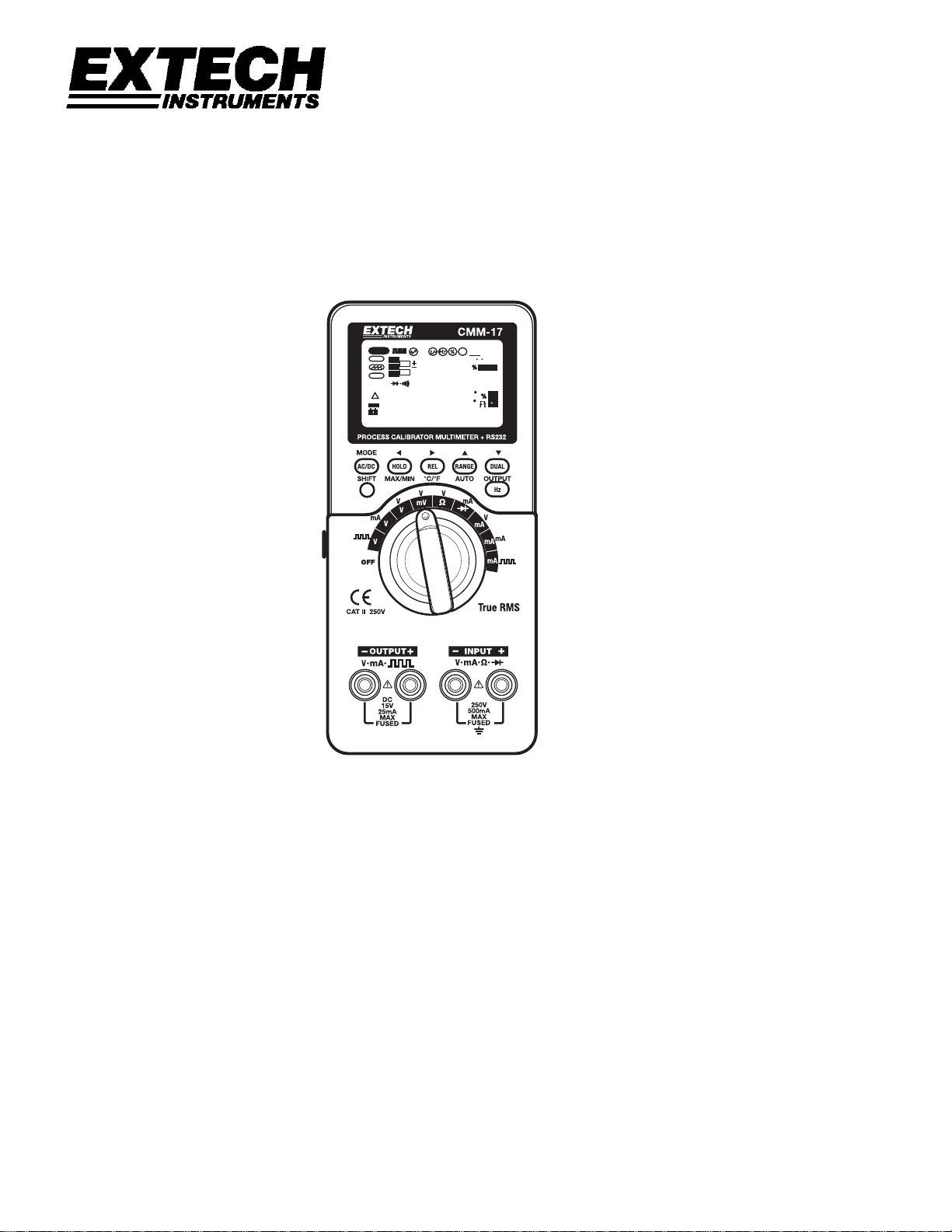
CMM-17 Process Calibrator Multimeter
• Constant Voltage
• mA Source
• Square Wave
Remote
SCAN
J
K
OUT
E
T
SBY
88888
R
S
SHIFT
AUTO
@
OFF
88888
MAX
AVG
ms
MIN
Level
ACDC
F
C
k
Hz
4-20
0-20
sec
m
µ
AV
ACDC
0-20
C
4-20
0C
F
sec
sec
m
m
AV
µ
µ
Ù
Hz
Mk
• Auto Scan/Ramp
• Dual Display Multimeter
• Rechargeable Batteries
This guide provides an overview of the meter. For more detailed information, refer to the
CMM-17 User’s Guide provided with the meter.
Page 2

Introduction
This process calibrator/meter is a hand-held, battery-operated instrument for testing and
troubleshooting power electronic systems. This device can be used not only for instrument
system maintenance, but also for maintaining, servicing industrial meters, testing electronic
circuits and electronic equipments. The meter can also be used to measure or calibrate
sensors or transmitters in automotive or automatic control system.
The meter generates a high precision constant voltage, constant current and square wave
output and includes a full feature, high accuracy multimeter. The precision source and the
measurement functions can perform simultaneously.
Main Features:
• Generates and Measures Signal simultaneously
• 1,200Ω drive capability with special yellow lead for 20mA simulation
• High precision Constant voltage, Constant Current and Square wave outputs
• Intelligent Output and Standby control
• Built-in Ni-MH rechargeable battery
• Smart Charger design without battery removal
• Brightness EL backlight
• Coarse or Fine output adjust
• The % scale readout for 4-20mA or 0-20mA
• Adjustable steps and time interval for Auto Scan
• Adjustable resolutions and start for linear Ramp output
• 1ms Peak hold to capture inrush voltage and current easily
• Temperature test with the option of 0°C compensation
• Frequency, Duty cycle and Pulse width measurements
• Dynamic Recording for MIN/MAX/AVG
• Data Hold with Manual or Auto Trigger and Relative modes
• Diode and Audible Continuity test
• Bi-directional optical computer interface with SCPI commands
• Safe, precise and fast closed-case calibration
• 50,000 count precision True-RMS digital multi-meter and designed to meet IEC-1010
CAT. II 250V standards
2
CMM-17 Quick Start V1.2 03/05
Page 3
SAFETY INFORMATION
A WARNING identifies conditions and actions that may cause hazard(s) to the user;
A CAUTION identifies conditions and actions that may damage this Device.
Table-1 International Electrical Symbols
AC and DC - Alternating and Direct Current
AC - Alternating Current
DC - Direct Current
Ground
Double Insulation
See Explanation In The Manual
To avoid electric shock, injury, or damage to this instrument:
• Read this operation manual completely before using this device and follow all safety
instructions.
• This device is for indoor use, altitude up to 2,000m.
• Avoid working alone.
• Use the device only as specified in this manual; otherwise, the protection provided by the
meter may be impaired.
• Never measure Voltage when the current measurement is selected.
• Do not use this device if it looks damaged.
• Inspect the leads for damaged insulation or exposed metal. Replace damaged leads.
• Disconnect the power and discharge all high-voltage capacitors before testing in the
resistance, continuity, and diode function.
• Use caution when working above 70V DC or 33V RMS and 46.7V peak, these voltages
may cause a shock hazard.
• Always keep your hands behind the protective guard of the probe when measuring.
• Select the proper function and disconnect the test leads from test points before changing
functions.
• Do not mix with different types of batteries. Always use specified battery.
• The meter is safety-certified in compliance with EN61010 (IEC 1010-1, IEC 1010-2-031)
Installation Category ΙΙ 250V Pollution Degree 2.
3
CMM-17 Quick Start V1.2 03/05
Page 4
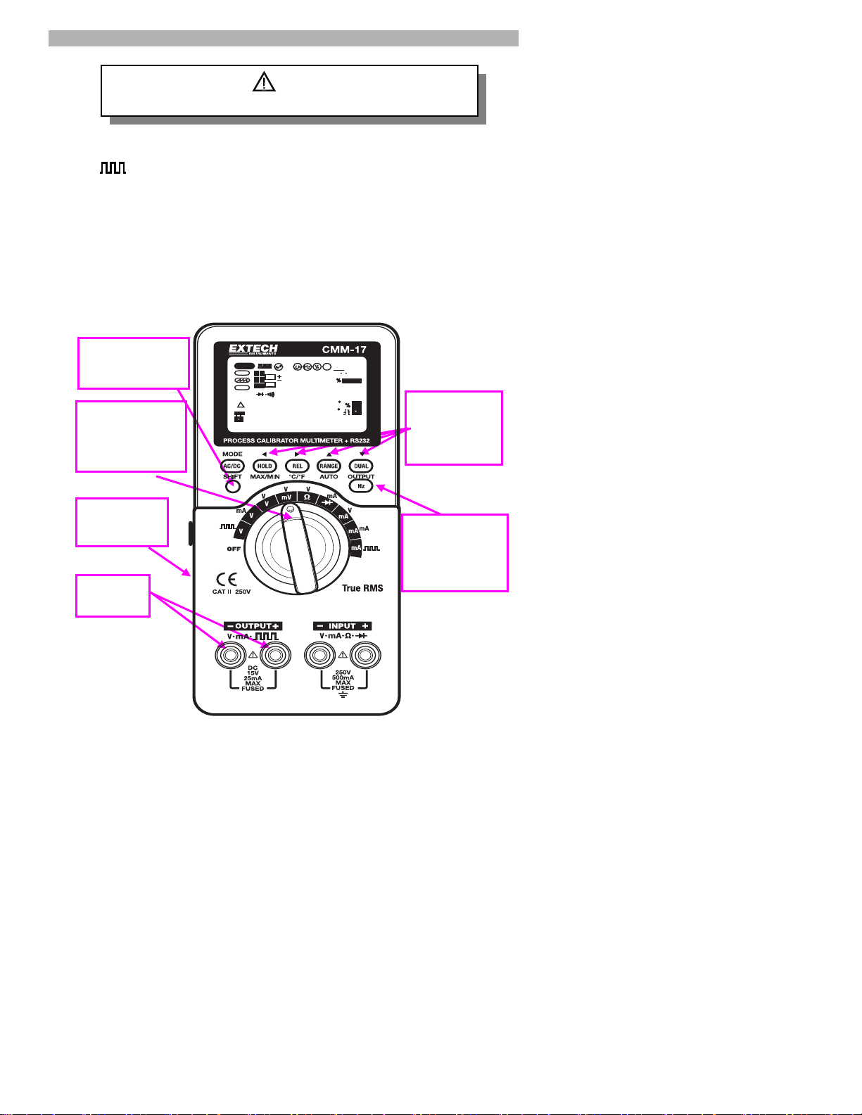
Setup and Output a process calibration signal
g
p
Read "SAFETY INFORMATION" before usin
1. Set the side switch on the left side to the M/S position
2. Turn the function switch to select combined function for the output function required
, mA, or V) and related input function will be used simultaneously.
(
3. Press the “SHIFT” button to shift the buttons for output setting.
4. Use the arrow buttons (3/ 4for digit selection, 5/ 6 for value) to set the output
value.
5. Connect the OUTPUT terminals to the device to be tested.
6. Press the OUTPUT button. The process signal will become active.
7. Press the OUTPUT button to return the output to the standby mode.
3. Press SHIFT
for output setting
2. Turn the
function switch to
select combined
1. Set switch
to M/S (side)
5. Output
Terminals
Figure-1 Quick Output Operation
WARNING
Remote
SCAN
SHIFT
AUTO
@
OFF
J
K
OUT
E
T
SBY
88888
R
S
MAX
88888
AVG
this
ms
Level
ACDC
F
C
k
Hz
4-20
0-20
sec
m
µ
AV
ACDC
MIN
0-20
C
4-20
0C
F
sec
sec
m
m
AV
µ
µ
Ù
Hz
Mk
4. Use the
arrow buttons
to set the
out
ut value.
6/7.
Press OUTPUT
button to toggle
signal ON/OFF
4
CMM-17 Quick Start V1.2 03/05
Page 5
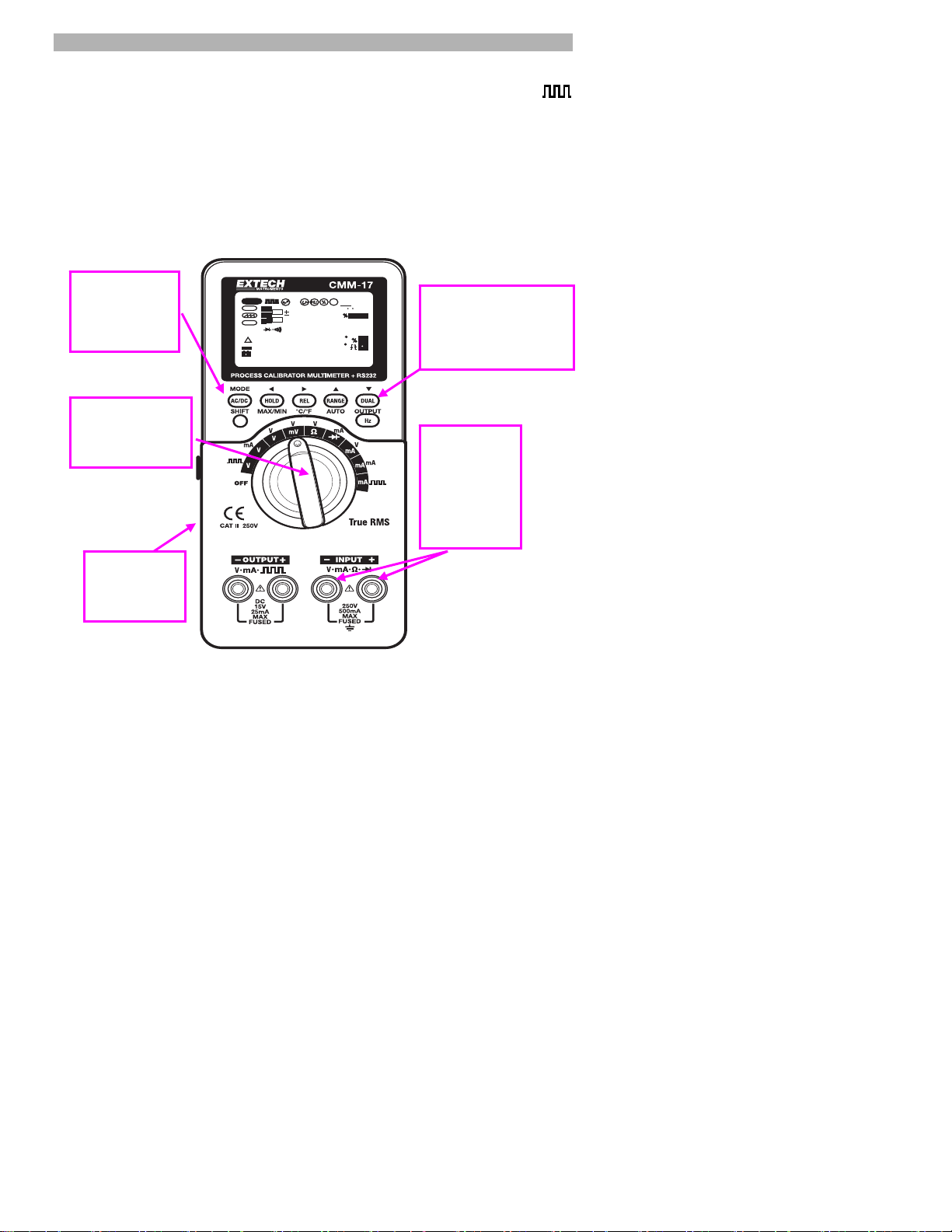
INPUT- ACV and Frequency Measurements
g
1. Set the side switch on the left side to the M or M/S position
2. Turn the rotary switch to select combined function for “V” and the output function (
mA or V) as desired.
3. Press the “AC/DC” button momentarily to select AC voltage measurement.
4. Press the “Dual” button momentarily to set frequency measuring on secondary display.
5. Connect the INPUT terminals by test leads to the source to be tested.
3. Press
momentarily to
select AC
volta
e test
2. Turn the
function switch to
“V” function
1. Set switch
to M or M/S
(side)
Remote
SCAN
J
K
E
T
R
S
SHIFT
AUTO
@
OFF
88888
Figure-2 ACV/ Hz Measurement
OUT
SBY
88888
MAX
ms
Level
ACDC
F
C
k
AVG
Hz
4-20
0-20
sec
m
µ
AV
ACDC
MIN
0-20
C
4-20
0C
F
sec
sec
m
m
AV
µ
µ
Ù
Hz
Mk
4. Press momentarily
to set frequency
measuring on
secondary display
5. Connect
the INPUT
terminals by
test leads to
the source to
be tested
,
5
CMM-17 Quick Start V1.2 03/05
Page 6
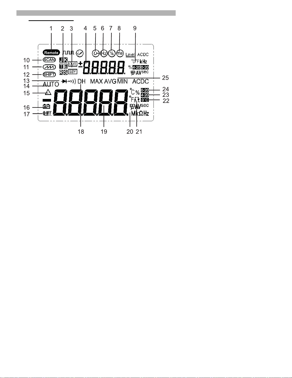
Display Illustration
GETTING STARTED
Figure-3 LCD Display
1. Remote control
2. Thermocouple type
3. Output enable/disable
4. Secondary display for output and input
5. Constant voltage output
6. Square wave output for Hz
7. Square wave output for %
8. Square wave output for mS
9. Output/input units
10. Scan output
11. Ramp output
12. Shift button operation
13. Diode/audible continuity
14. Auto range
15. Relative mode
16. Low battery
17. Auto power off icon
18. Data Hold (manual trigger)
19. Primary display for input
20. Input units
21. Positive/negative trigger slope for % and mS tests
22. Without ambient temperature compensation
23. % 4-20/4-20mA
24. % 0-20/0-20mA
25. Dynamic recording
6
CMM-17 Quick Start V1.2 03/05
Page 7
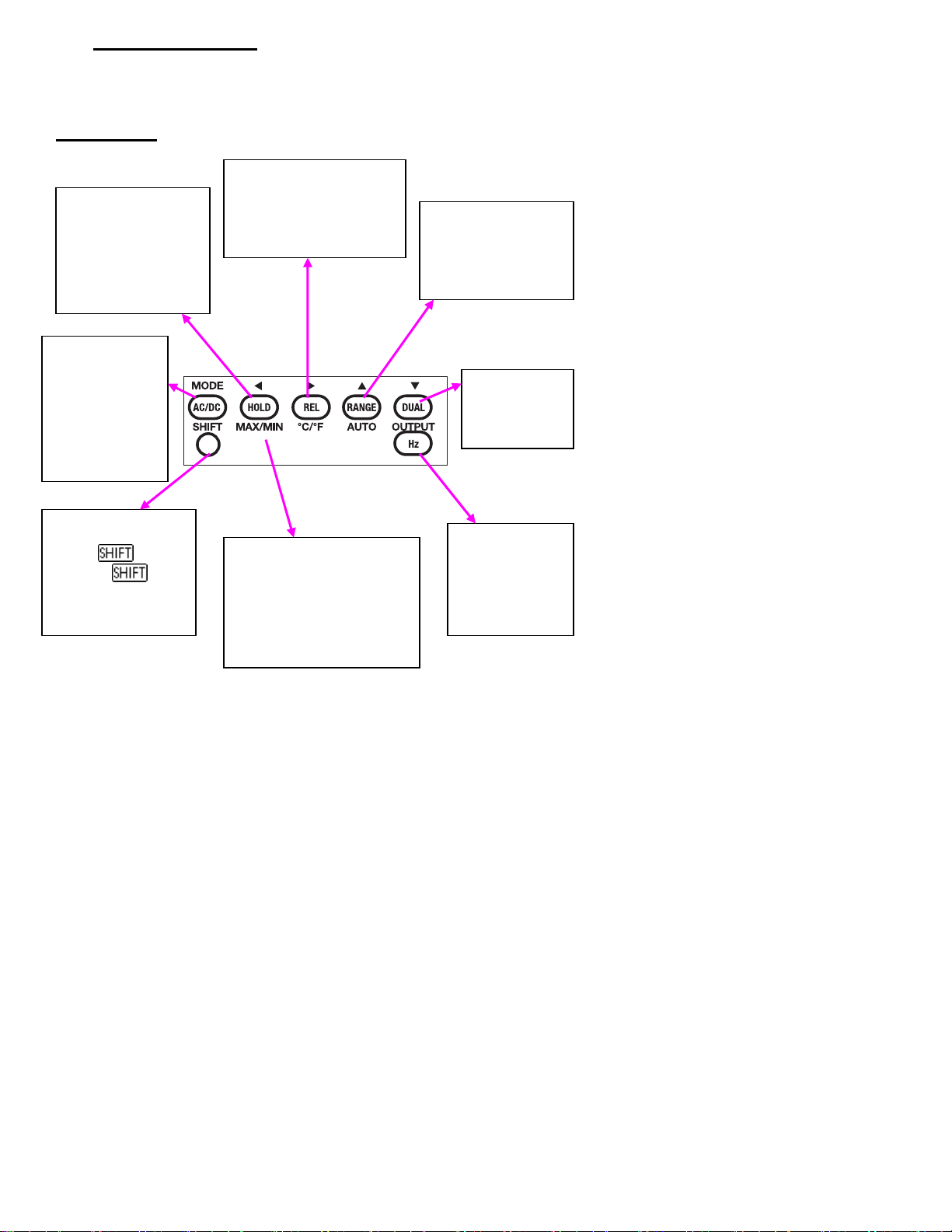
Pushbutton Operation
The operation of the push-buttons is shown below. When a button is pressed, a
related symbol will be lit, and the beeper will sound. Turning the rotary switch to
another position will reset current operation of the push buttons.
INPUT BUTTONS
HOLD: Freeze existing
measured value. Press
again to trigger next
measuring value
Press and hold for
more than 1sec. to exit
data trigger hold.
BLUE: To select
DC, AC or AC+DC
measuring
PEAK: Press and
hold for more than
1 sec. to toggle
PEAK Hold
ON/OFF for V/ mA
SHIFT: Press to shift
button operation for
INPUT (
OUTPUT (
: Press and hold for
more than 1 sec. to
toggle backlit ON/OFF
OFF) or
ON)
REL: Set the value on the
display to be subtracted.
°C°F: Press and hold for
more than 1 sec. to toggle
mV and temperature tests.
MAX MIN: Press and hold for
more than 1 sec to toggle
Dynamic recording mode.
Press this button momentarily
to cycle through MAX, MIN,
AVG and present (MAX AVG
MIN) readings at recording
mode.
Figure-4 Input Buttons
RANGE: Change
measuring range.
AUTO: Press and hold
for more than 1 sec. to
set Auto-range
DUAL: Select
different
combination
displays
Hz: Select Hz, %
and Pulse width
tests on Primary
display. Press and
hold for more than
1 sec. to exit.
7
CMM-17 Quick Start V1.2 03/05
Page 8
OUTPUT BUTTONS
←
→
←
→
←
→
←
→
←
→
←→±
3 (LEFT)/ 4 (RIGHT):
Select which Digits or polarity to be adjusted
For voltage and current output, press this button momentarily to select which Digits
or polarity to be adjusted. The selected position will flash on the secondary display.
MODE:
Select output modes for CV (CC),
SCAN and RAMP.
Select Hz, %, pulse width and
Level adjustments for Square
wave output.
SHIFT: Press to shift button operation
for INPUT (
OUTPUT (
: Press and hold for more than 1
sec. to toggle backlit ON/OFF
OFF) or
ON)
D5
±
Figure-5 Output Buttons
D4
D3
D2
5 (UP)/ 6(DOWN):
Adjust digit or polarity
Press momentarily to increase/
decrease 1 count for present digit or
toggle the polarity of output state.
OUTPUT: Press momentarily to toggle the
output state ON and OFF. The
means this signal has been sent out, and
means the signal has been disabled
output.
D1
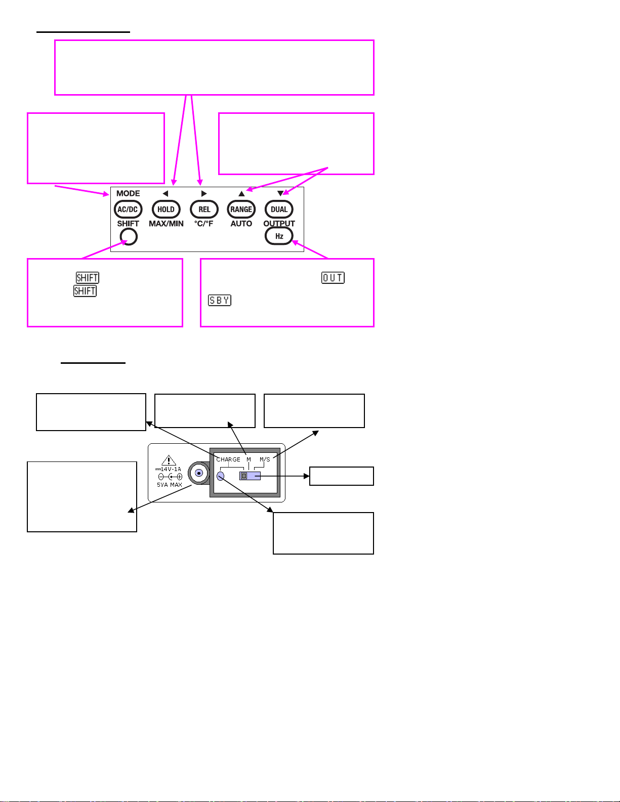
Slide Switch
Turn the slide switch to the position accordingly:
Charge: Charge batteries
by using the standard DC
adapter
External DC adaptor
jack:
Plug in the external DC
adapter to charge the
batteries or to power the
device.
M: Provide power for
Meter (INPUT) only.
Figure-6 Slide Switch
M/S: Provide power for
Measuring and Source
Charging indication
Green: Fully charged
Red: Under charged
Slide Switch
8
CMM-17 Quick Start V1.2 03/05
Page 9

Rotary Switch
Set the slide switch to the M or M/S position. Turn the meter ON and select the combined
function you desire by turning the rotary switch.
1
5
2
6
Figure-7 Rotary Switch for selecting combined function
FUNC.
1 Power Off
2
3 DC, AC or DC+AC mV measurements.
4 Resistance/ Continuity measurements
5 Diode/ Audible Continuity.
DC, AC or DC+AC mA measurements:
6
INPUT (White color) OUTPUT (Yellow Color)
DC, AC or DC+AC Voltage
measurements.
50mA and 500 mA
Output and Input Terminals
OUTPUT terminals for Constant
Voltage, Constant Current and
Square wave Output functions
Constant current: ± 25 mA
Constant voltage: ± 1.5V, ± 15V
Constant voltage: ± 1.5V, ± 15V
Constant voltage: ± 1.5V, ± 15V
Constant current: ± 25 mA
Constant voltage: ± 1.5V, ± 15V
Constant current: ± 25 mA
INPUT terminals for Voltage,
Current, Resistance, Diode/ Audible
Continuity measurements
Square wave output
Square wave output
9
CMM-17 Quick Start V1.2 03/05
Figure-8 Output/Input Terminals
Page 10

HOW TO ENTER SETUP MODE
Press and hold the MODE button while turning the rotary switch to any ON position. The meter
will enter setup mode, these parameters will be saved in non-volatile memory even when the
meter is turned off.
Changing the parameters in setup mode:
1. Press “
2. Press “
3. Push “
4. Push “
The following table describes the setup menu items, the factory settings and user selectable
parameters.
3
5
OUTPUT
SHIFT
Menu item
Baud Rate 9600 2400, 4800, 9600 and 19200
Parity None Odd, even or none
Data bit 8 8 bits or 7 bits (Stop bit is always 1 bit)
ECHO OFF ON or OFF
Printer-Only OFF ON or OFF
Percentage scale 4-20mA 4-20mA and 0-20mA for % scale readout
” or “
(LEFT)
(UP) or 6(DOWN)
” button momentarily to exit setup mode.
(RIGHT)
4
” button momentarily to save your setting.
Factory
Setting
” button to select which menu item to be set.
” button to change the parameter.
Table-2 Descriptions for Setup Menu Items
Selectable Parameters
Frequency 0.5Hz Set minimum measuring frequency, 0.5, 1 or 2 Hz.
Beeper 4800
Temperature
Refresh Hold OFF
Auto power off 15 0~99 minutes, “0” disables auto power off.
Backlight 30
Notes: Push the “
option. The “
SHIFT
°C/°F
” button for more than one second to enable temperature
” symbol will appear on the display.
The driving frequency can be set for
4800,2400,1200 or 600 Hz. “OFF” disables the
beeper
Four combinations can be set:
1. °C only
2. °C and °F
3. °F only
4. °F and °C
OFF means Data Hold, set 100~1000 variation
counts to enable refresh hold.
0~99 seconds, “0” disables turning off the backlight
automatically.
10
CMM-17 Quick Start V1.2 03/05
 Loading...