

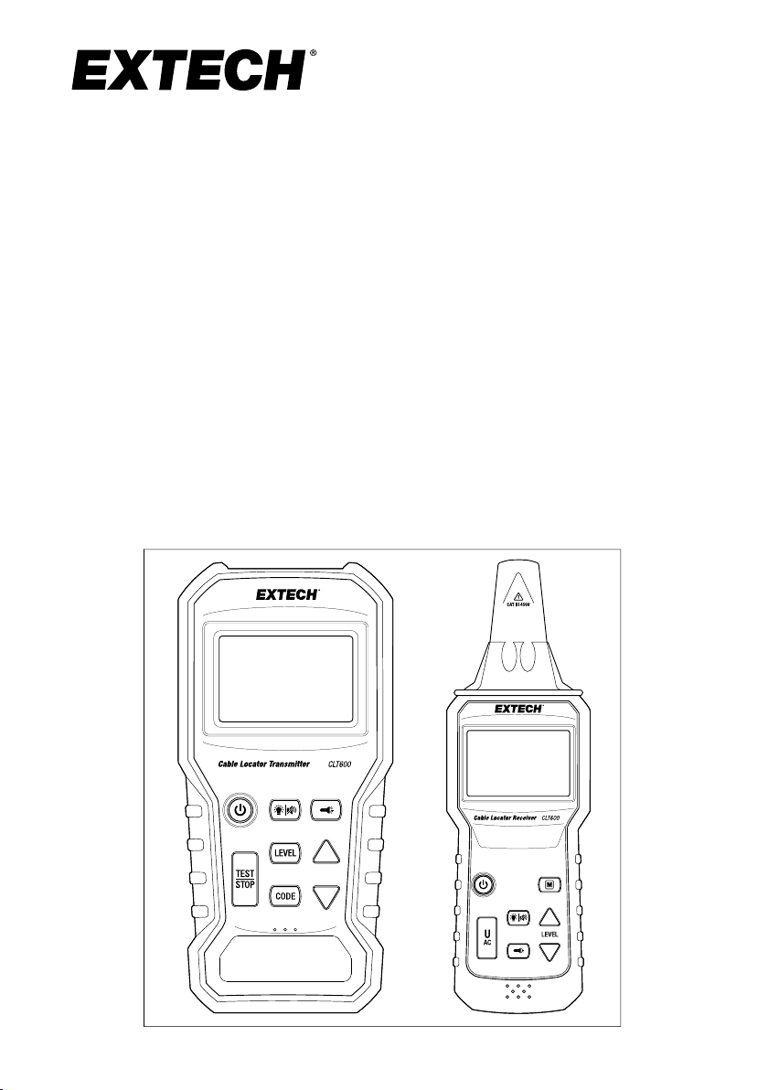
User Manual
CLT600 Cable Locator
and Tracer

Table of contents
1 Introduction........ ........ ................ ........... ........ ........... ..........1
1.1 Transmitter Features ......... ........ ........ ........ ........... ....... 1
1.2 Receiver Features ........ ........... ........ ........ ........ ........... 1
1.3 Common Features ....... ........ ........... ................ ........ .... 1
1.4 Supplied Materials .......... ........ ........ ... ........ ........ ........ . 2
2 Safety ........... ........ ........... ........ ........ ........ ........... ........ .......3
2.1 Safety Notes..... ........ ........ ........ ........... ........ ........ ...... 3
2.2 International Safety Symbols..... ........... ........ ........ ........ . 3
3 Product Description . ... ..... ........... ........ ........ ... ................ .....4
3.1 Transmitter Description ... ........ ........... ........ ........ .......... 4
3.2 Receiver Description ..... ........ ................ ... ........ ........ ... 6
3.3 Display Description .. ........ ........... ........ ................ ........7
4 Transmitter Operating Modes ....... ........ ........... ................ .....9
4.1 Transmitter TESTand TRANSMIT Mode .............. ........ .... 9
4.2 Transmitter LEVEL Selection Mode.. ..... ... ........ ........ ....... 9
4.3 CODE Selection Mode..... ........ ........... ........ ........ ... ..... . 9
5 Receiver Operating Modes ...... ........ ........... ........ ........ ........ 10
5.1 Automatic Detection Mode.. ..... ........... ........ ........... ..... 10
5.2 Manual Detection Mode .. ........ ........... ........ ........ ........ 10
5.3 Non-Contact Voltage Detection Mode (U
6 Applications ...... ........ ........... ........ ........ ........ ........... ........ . 11
6.1 Single-pole applications ....... ........... ........ ........ ........... 11
6.1.1 Locating Opened Wires....... ........ ........ ........... . 11
6.1.2 Locating and Tracing Lines and
Receptacles . ........ ........... ..... ... ........ ........ ..... 11
6.2 Two-pole Applications........... ........ ................ ........... .. 13
6.2.1 Tracing Connections ...... ........ ........ ........ ......... 13
6.2.2 Broken Line Detection ...... ........ ... ........ ........ .... 14
6.3 Other Applications . ........ ........ ........ ........... ........ ........ 15
6.3.1 Tracing an Underground Circuit..... ........ ........... . 15
6.3.2 Detecting Faults in a Floor Heating
System .. ................ ........... ........ ........... ........ 15
6.3.3 Detecting Faults in a Floor Heating System
(using two kits) . ........ ........ ... ................ ........ .. 16
6.3.4 Non-Contact Voltage Detection ..... ........... ........ . 17
6.3.5 Using the Ground Spike.... ........ ........... ........ .... 18
)... ........... ...... 10
AC
#NAS100035; r. AA/71038/71038; en-US ii

Table of contents
7 Maintenance..... ........ ........... ........ ........ ................... ........ .. 19
7.1 Battery Replacement (Transmitter) ..... ........ ........ ........ .. 19
7.2 Battery Replacement (Receiver) .... ........... ........ ........ ... 19
7.3 Cleaning and Storage ........ ........ ........ ........... ........ ..... 20
8 Specifications.... ........... ........ ........ ... ................ ........ ........ . 21
8.1 Transmitter Specifications........ ........ ... ........ ........ ........ 21
8.2 Receiver Specifications.. ................ ........ ........ ... ........ . 21
8.3 General Specifications.... ... ..... ........... ........ ........ ... ..... 22
9 Warranty and Customer Support . ... ........ ........ ........ ........ ... .. 23
9.1 Two-Year Warranty ...... ........ ........... ........ ........ ........... 23
9.2 Calibration and Repair Services..... ........ ........ ........ ...... 23
9.3 Contact Customer Support ..... ........ ........ ........... ........ . 23
#NAS100035; r. AA/71038/71038; en-US iii


1
Introduction
Thank you for selecting the Extech CLT600 Cable Locator and Tracer. The
system allows you to easily locate cable faults, diagnose and trace cables and
circuits, test AC outlet wiring, detect faults in floor heating systems, perform
non-contact voltage detection on energized circuits, locate fuses or breakers
on panels, and more.
The CLT600 includes a Transmitter that can measure voltage and inject signals through cables or pipes, and a Receiver for tracing the transmitted signals. The Receiver also detects voltage in the non-contact voltage detection
mode.
These instruments are shipped fully tested and, with proper use, they will provide years of reliable service. Please visit our website (www.extech.com) for
additional information including the latest version of this User Manual and
Customer Support.
1.1 Transmitter Features
• Locates and identifies powered and de-energized cables and individual
conductors.
• Measures voltage from 12 V ~ 450 V AC / DC using the supplied test leads.
• Transmits high frequency signal through wires or pipes.
• Selectable transmission power level setting (1 ~ 3).
• Selectable transmission signal codes.
• Transmission power level bar graph indicator.
1.2 Receiver Features
• Identifies and traces powered or de-energized wires and cables.
• Traces signal sent from Transmitter.
• Displays the Level setting, Code, and strength of detected signal.
• Bar graph and variable tone indicate detected signal strength.
• Auto and Manual signal detection modes.
• Selectable Sensitivity (8 levels) in Manual mode.
• Non-contact voltage detection.
• Warning display and audible tone when voltage is detected.
1.3 Common Features
• LED Worklights.
• Backlit display.
• Silent mode of operation with button beeper and frequency tone disabled.
• Automatic power off (APO).
#NAS100035; r. AA/71038/71038; en-US
1

1
Introduction
• Battery status indication.
1.4 Supplied Materials
This kit includes the following items.
• Transmitter and Receiver.
• Printed Quick Start.
• Test lead set.
• Alligator clips (2).
• Earth ground rod/spike.
• Batteries (12).
• Socket adapter with North America 3 pin (type B) plug.
• Hard-shell carrying case.
#NAS100035; r. AA/71038/71038; en-US
2
2
Safety
NOTE
These devices have been designed and tested according to CE Safety Requirements for
Electronic Measuring Apparatus, EN 61010-1 EN 61326-1 and other safety standards. Follow
all warnings to ensure safe operation.
WARNING
Read the safety notes, below, before using this device.
2.1 Safety Notes
• Read the following safety information carefully before attempting to operate
or service these devices.
• Use these devices only as specified in this manual, otherwise the protection provided by these devices may be impaired.
• Rated environmental conditions:
1. Indoor use only.
2. Installation Category III 450 V.
3. Pollution Degree 2.
4. Altitude up to 2000 m (6562’).
5. Relative Humidity 80% maximum.
6. Ambient temperature: 32 ~ 104℉ (0 ~ 40℃).
2.2 International Safety Symbols
Figure 2.1 Meter is protected throughout by double insulation or reinforced insulation.
Figure 2.2 Warning! Risk of electrical shock.
Figure 2.3 Caution! Refer to this manual before using this meter.
Figure 2.4 Earth Ground.
#NAS100035; r. AA/71038/71038; en-US
3
3
Product Description
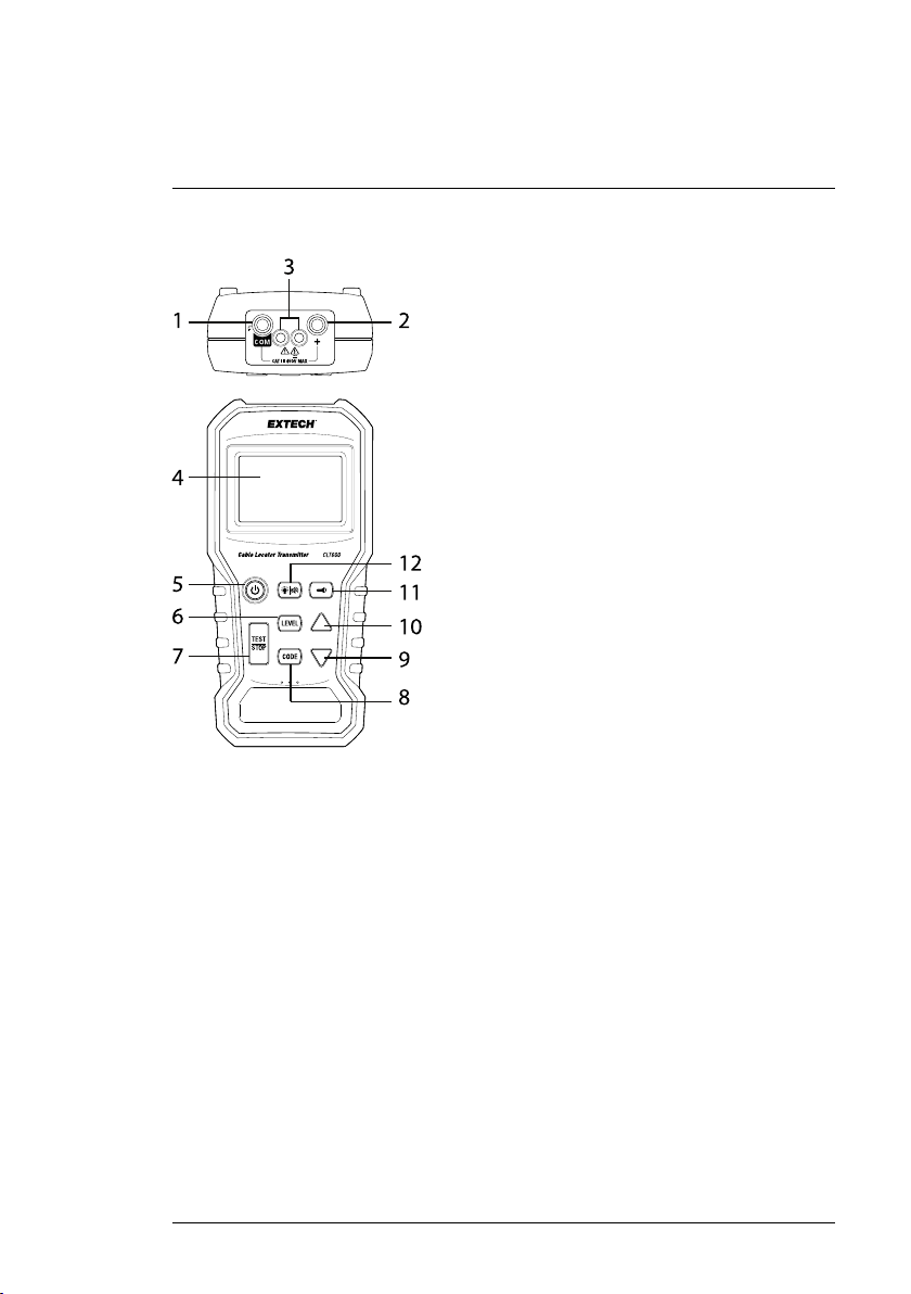
3.1 Transmitter Description
1. Negative (COM) terminal
This is the ground, or common, terminal. Connect the black test lead to
this terminal.
2. Positive ‘+’ terminal
Connect the red test lead to this terminal.
3. Worklight
4. LCD Screen
5. Power ON/OFF button
Short press to switch ON or OFF
6. LEVEL button
Short press to access the Level selection mode. The ‘LEVEL’ text will flash
on the display. Use the arrow buttons to select from three available signal
levels.
#NAS100035; r. AA/71038/71038; en-US
4

3
Product Description
7. TEST/STOP button
Press to send or to stop the transmission signal.
8. CODE button
Long press this button to access the Code selection mode. The ‘CODE’
text will flash on the display. Use the arrow buttons to scroll through and
select an optional code (F, E, H, d, L, C, O, A). This feature is handy in
identifying Transmitters when 2 or more CLT600 systems are used.
9. Down arrow button
Short press to increase the signal level in the LEVEL mode or to scroll
through the codes in the CODE selection mode.
10. Up arrow button
Short press to decrease the signal level in the LEVEL mode or to scroll
through the codes in the CODE selection mode.
11. Worklight button
Short press to switch the Worklights ON or OFF.
12. Backlight and Mute button
Short press to switch the LCD backlight ON or OFF. Long press to switch
the beeper ON or OFF.
The battery compartment is located on the back of the instrument.
#NAS100035; r. AA/71038/71038; en-US
5

3
Product Description
3.2 Receiver Description
1. Receiver Antenna
Detects and traces a transmitted signal or a voltage source in the non-contact detector mode.
2. Worklights
3. LCD
4. Backlight and Mute button
Short press to switch the LCD backlight ON or OFF. Long press to switch
the beeper ON or OFF.
5. Power ON/OFF button
Short press to switch ON or OFF
6. U
AC
button
Short press to access the non-contact voltage detection mode. Press
again to return to normal Receiver mode.
7. Worklight button
Short press to switch the Worklights ON or OFF.
#NAS100035; r. AA/71038/71038; en-US
6

3
Product Description
8. Down arrow button
Short press to decrease the sensitivity level in the Manual signal detection
mode.
9. Up arrow button
Short press to increase the sensitivity level in the Manual signal detection
mode.
10. Manual (M) button
Short press to access the Manual signal detection mode. Select from eight
sensitivity levels using the LEVEL buttons.
The battery compartment is located on the back of the instrument.
3.3 Display Description
Figure 3.1 Display Description
1. Battery status.
2. Beeper ON/OFF status.
3. Voltage warning.
4. Signal indicator (indicates that the digital display is showing the received
signal strength).
5. Manual detection mode.
6. Automatic detection mode.
7. Voltage AC or DC (digital display is showing an AC or DC voltage
measurement).
8. Digital display for voltage measurement (Transmitter) or strength of detected signal (Receiver).
9. Transmission strength (Level) selection.
10. Code ID indication.
#NAS100035; r. AA/71038/71038; en-US
7

3
Product Description
11. Signal indicator. Radiating arc graphics appear when Transmitter is sending a signal. On the Receiver, the number of arcs corresponds to the receiver 'sensitivity level'.
12. Bar-graph shows signal level.
#NAS100035; r. AA/71038/71038; en-US
8

4
Transmitter Operating Modes
4.1 Transmitter TESTand TRANSMIT Mode
When the power is on, the Transmitter defaults to the Test mode. In this mode
you can measure AC or DC voltage with the test leads. In this mode you can
also transmit a signal. Press the TEST/STOP button to allow the Transmitter
to send a signal. Press the TEST/STOP button again to switch the signal OFF.
4.2 Transmitter LEVEL Selection Mode
Press the LEVEL button to access the transmission strength selection mode,
the ‘LEVEL’ symbol text will flash. Use the up/down arrow buttons to select
the strength of the transmission signal (level: 1~3). Press the LEVEL button
again to return to the Test Mode. Select signal level ‘3’ when using the ground
spike.
4.3 CODE Selection Mode
Codes can be used to differentiate two or more transmitters that are being
used to detect a break in a circuit.
Long press the CODE button to access the code selection mode, the ‘CODE’
text symbol will flash. Use the up/down arrow buttons to select a code (F, E, H,
d, L, C, O, A). Press the CODE button again to return to the Test Mode.
#NAS100035; r. AA/71038/71038; en-US
9

5
Receiver Operating Modes
5.1 Automatic Detection Mode
When the power is on, the Receiver defaults to the auto detection mode
where it can trace the high frequency transmission signal at the highest sensitivity. The Receiver responds to the detected signal with a variable tone (550
Hz ~ 1.6 kHz) and a bar-graph indication. The stronger the signal, the higher
the frequency of the tone and the higher the number of bars in the bar-graph.
The receiver displays SIG (Signal) and the numeric value of the received signal strength. The optional transmission identifier Code, sent from the Transmitter, is also displayed.
5.2 Manual Detection Mode
Press the M button to access the manual detection mode where you can select the signal sensitivity level (8 steps) using the up/down arrow buttons.
Press the M button to return to the Auto Detection mode.
5.3 Non-Contact Voltage Detection Mode (U
Press the U
this mode you can detect a voltage source without having to make contact
with the wiring, circuit, AC power line, or wall outlet.
button to access the non-contact voltage detection mode. In
AC
AC
)
#NAS100035; r. AA/71038/71038; en-US
10

6
Applications
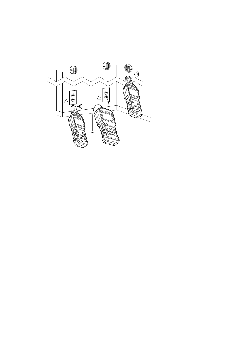
6.1 Single-pole applications
6.1.1 Locating Opened Wires
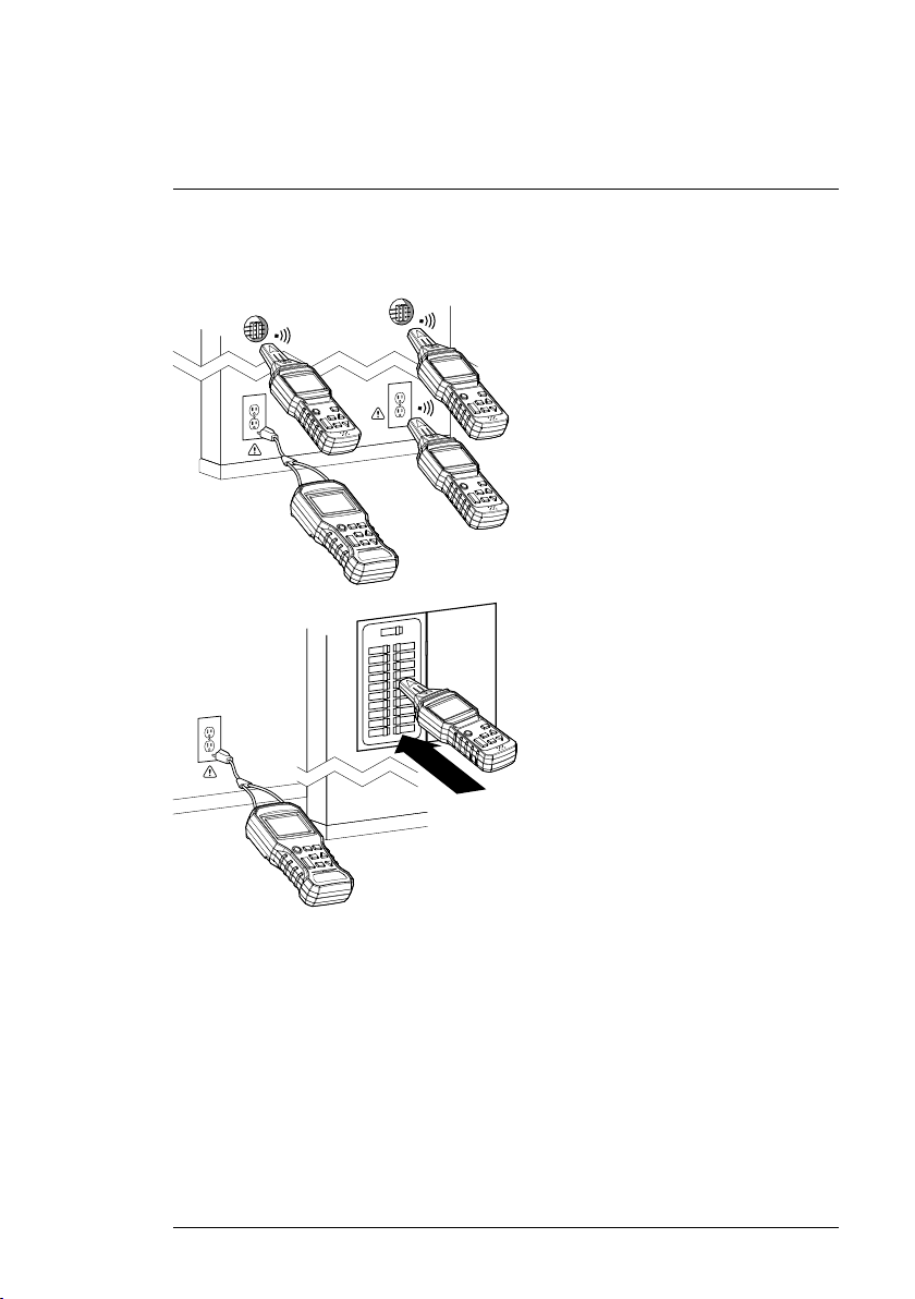
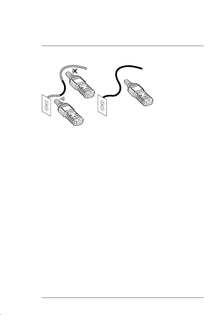
Figure 6.1 Locating opened wires. Diagram shows one transmitter in a fixed location and
one Receiver being used in two locations. The Receiver position on the left is detecting a signal, while the Receiver position on the right is not detecting a signal.
1. Connect the red, positive (+) terminal to a single conductor.
2. Connect the black (COM) terminal to earth ground. If convenient, use the
supplied ground spike for an outdoor earth ground connection.
3. If there are additional conductors in the same conduit or cable, they will also have to be connected to earth ground.
4. The Receiver can now detect the location of the wiring fault.
6.1.2 Locating and Tracing Lines and Receptacles
WARNING
Do not perform this test on a live circuit.
#NAS100035; r. AA/71038/71038; en-US
11
6
!
!
Applications
Figure 6.2 Locating and Tracing Lines and Receptacles
1. Connect the red, positive (+) terminal to the live (hot) conductor.
2. Connect the black (COM) terminal to earth ground. When working outdoors, you can use the supplied ground spike for an earth ground
connection.
3. Note that if the signal carrying cable is near other conductors, in parallel,
(cable tray, channel, etc.) or is interlaced or crossed with these conductors, signals may propagate into a cable and create spurious signals that
could be detected.
#NAS100035; r. AA/71038/71038; en-US
12
6
Applications
6.2 Two-pole Applications
6.2.1 Tracing Connections
Figure 6.3 Matching connected points in a circuit.
1. Connect the supplied Socket Adaptor to the Transmitter and plug the AC
connector into an AC receptacle.
2. The Transmitter can now measure the voltage of the mains and transmit
the signal through the mains.
3. The Receiver can then trace the mains and determine if the receptacle is
located on the same line, if another receptacle or breaker is connected on
the same circuit'.
#NAS100035; r. AA/71038/71038; en-US
13
6
Applications
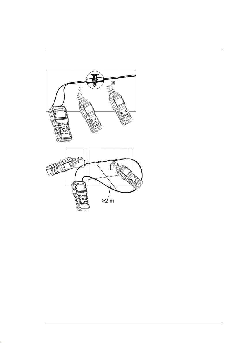
6.2.2 Broken Line Detection
Figure 6.4 Two Examples of Broken Line Detection (the top diagram shows a two-conductor
test, while the bottom diagram shows a single-conductor test). Diagrams show one transmitter in a fixed location and one Receiver being used in two locations. On the top diagram, the
Receiver position on the left is detecting a signal, while the Receiver position on the right is
not detecting a signal.
1. Method 1: Connect both terminals of the transmitter, one to each wire, at
one end of the line. At the other end of the line, connect the wires together.
2. Method 2: Connect both terminals of the transmitter to each end of a single wire in the line.
3. The Receiver can now determine the position of the broken wire in the signal line in the wall or floor.
#NAS100035; r. AA/71038/71038; en-US
14
6
Applications
6.3 Other Applications
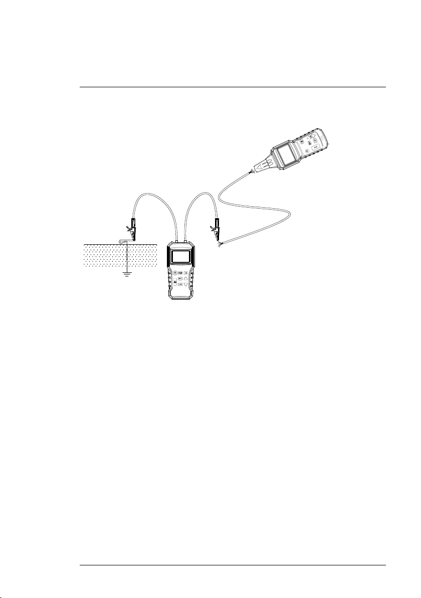
6.3.1 Tracing an Underground Circuit
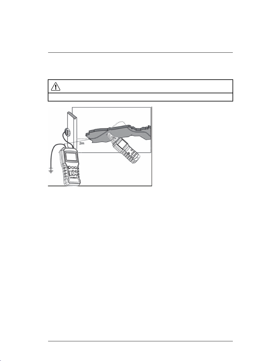
WARNING
The circuit under test must not be live.
Figure 6.5 Tracing Underground Circuits
1. Connect the Transmitter’s positive (+) terminal as shown in the diagram.
2. The Transmitter’s COM terminal must be correctly connected to earth
ground. When working outdoors, you can use the supplied ground spike
for an earth ground connection.
3. Use the Auto Detect mode of the Receiver to locate and trace the circuit.
4. The distance between the earth wire and the circuit to be located must be
as wide as possible, otherwise the earth connection may interfere with the
detection of the circuit line.
6.3.2 Detecting Faults in a Floor Heating System
Refer to the application image in Figure 6.1 earlier in this manual for a visual
example.
1. Connect the red, positive (+) terminal to a single conductor.
2. Connect the black (COM) terminal to earth ground. When working outdoors, you can use the supplied ground spike for an earth ground
connection.
3. If there are additional conductors in the same conduit or cable, they will also have to be connected to earth ground.
4. The Receiver can now detect a broken wire location.
#NAS100035; r. AA/71038/71038; en-US
15
6
Applications
6.3.3 Detecting Faults in a Floor Heating System (using two kits)
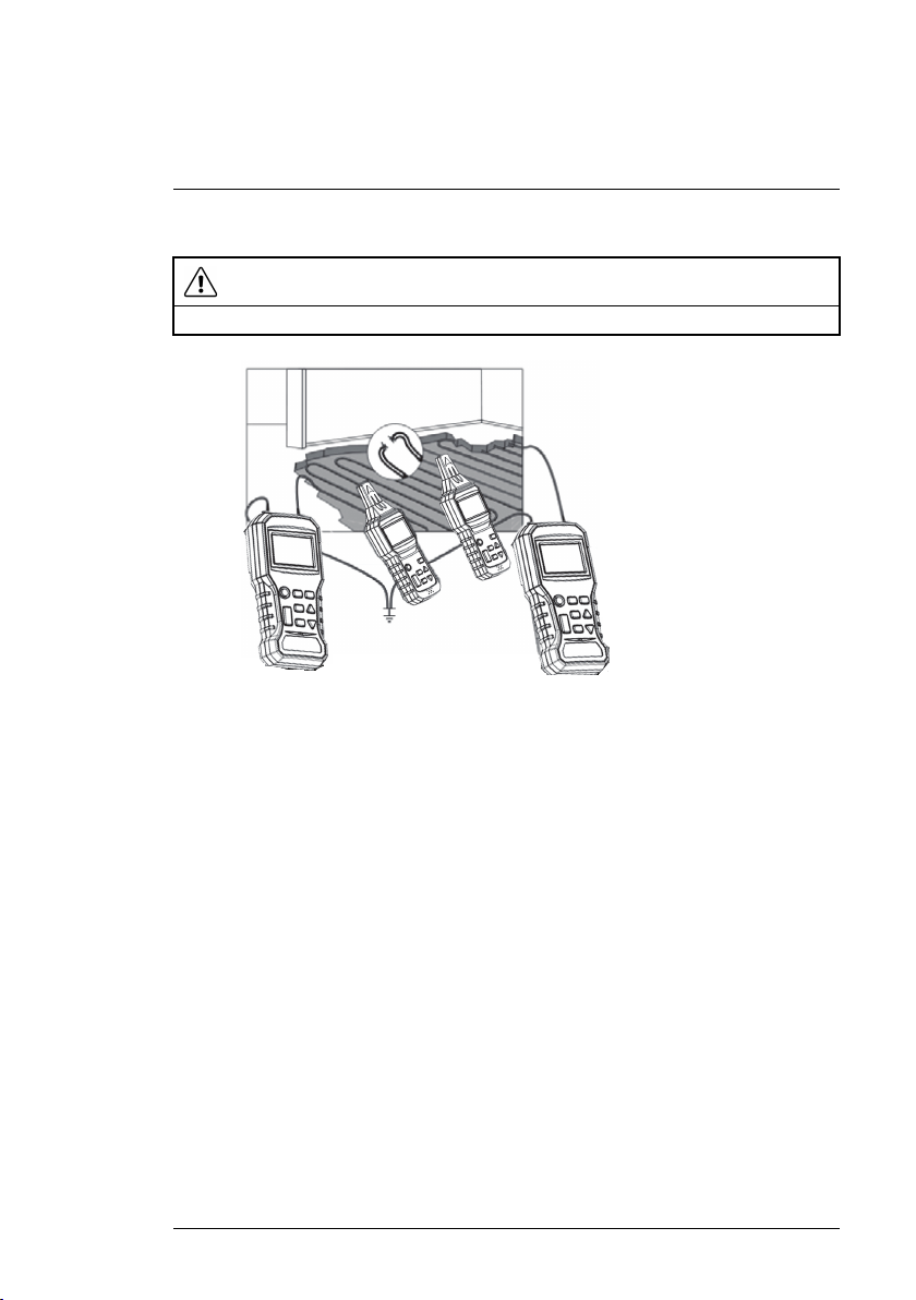
WARNING
The circuit under test must not be live.
Figure 6.6 Detecting Faults in a Floor Heating System
1. The right end of the circuit is connected to the Transmitter that is sending
an ‘x’ Code signal, and the left side of the circuit is connected to the other
Transmitter that is sending a ‘y’ Code signal (both Transmitters must be
earth grounded). The 'x' and 'y' codes used in this example represent the
transmission codes that the user can program to identify which transmitter
is being detected (see more about Codes in Section 4.1, Transmitter Op-
erating Modes).
2. When the line is traced, the place at which the signal, detected by the Receiver, falls off suddenly is the location of the break.
#NAS100035; r. AA/71038/71038; en-US
16
6
Applications
6.3.4 Non-Contact Voltage Detection
Figure 6.7 Non-Contact Voltage Detection
1. The circuit under test must be live and connected to the mains.
2. Set the Receiver to the U
AC
mode.
3. Hold the tip of the Receiver close to the source of AC voltage to test.
4. The mains AC voltage detected by the Receiver in the U
mode only indi-
AC
cates whether or not the circuit is live.
5. While searching for the ends of the supply lines, the lines must be connected separately, one by one.
6. The number of bars on the bar graph and the frequency of the audible
tone increases as the strength of the detected signal increases. The closer the sensor is to the source of voltage, the stronger the signal detection.
#NAS100035; r. AA/71038/71038; en-US
17
6
U
AC
MANU
RECE IVER
LEVE
L
TRAN SM ITTER
CAT III 450V
Applications
6.3.5 Using the Ground Spike
Figure 6.8 Earth Ground Spike
1. Refer to the accompanying diagram.
2. In applications that require an earth ground connection, you can use the
supplied ground rod (spike) for convenience.
3. Carefully drive the supplied rod into the ground at the test area.
4. Connect the test leads and set up the test as shown in the application instructions in the accompanying sections.
#NAS100035; r. AA/71038/71038; en-US
18
7
Maintenance
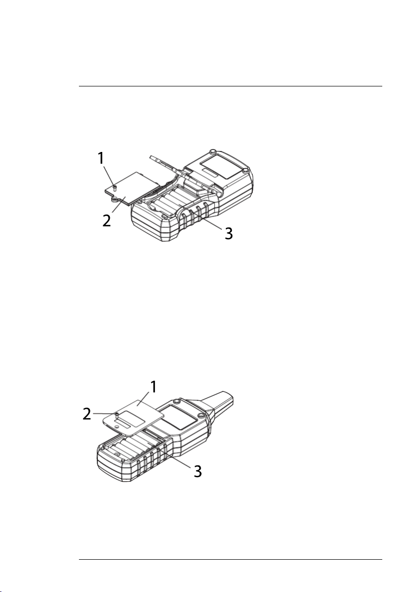
7.1 Battery Replacement (Transmitter)
When the battery symbol appears and flashes on the LCD, replace the batteries as follows:
Figure 7.1 Replacing Transmitter Batteries
• Disconnect the test leads from the Transmitter and switch off the Transmit-
ter’s power.
• Open the battery compartment by first removing the compartment screw
(1) and then removing the cover (2).
• Replace the batteries (1.5 V AAA x 6) observing correct polarity (3).
• Replace the compartment cover securely before operating the Transmitter.
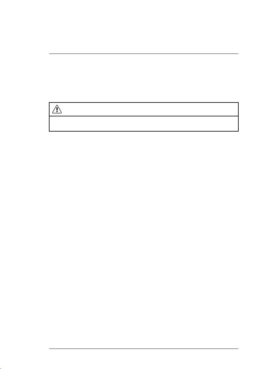
7.2 Battery Replacement (Receiver)
When the battery symbol appears and flashes on the LCD, replace the batteries as follows:
Figure 7.2 Replacing the Receiver’s Batteries
• Switch off the Receiver’s power.
#NAS100035; r. AA/71038/71038; en-US
19
7
Maintenance
• Open the battery compartment by first removing the compartment screw
(2) and then removing the cover (1).
• Replace the batteries (1.5 V AAA x 6) observing correct polarity (3).
• Replace the compartment cover securely before operating the Receiver.
7.3 Cleaning and Storage
WARNING
To avoid electrical shock or damage to the instrument, do not allow water to access the
housing.
• Periodically wipe the cases with a damp cloth and mild detergent. Do not
use abrasives or solvents.
• If the instruments are not to be used for > 60 days, please remove the bat-
teries and store them separately.
#NAS100035; r. AA/71038/71038; en-US
20

8
Specifications
8.1 Transmitter Specifications
Output signal frequency 125 kHz
Voltage measurement range
Voltage measurement accuracy ± (2% reading + 2 digits)
Display Backlit LCD with bar graph
Function displays Transmission signal level, Voltage meas-
Power source 1.5 V (AAA) battery x 6
Fuse 690 V / 0.5 A (6.3 x 32 mm)
Operating temperature and humidity 32℉ ~ 104℉ (0℃ ~ 40℃) 80% R.H. Max.
Storage temperature and humidity 14℉ ~ 122℉ (–10℃ ~ 50℃) 80% R.H.
Dimensions 188 (L) × 90 (W) × 47 (D) mm
Weight 13.7 oz. (389 g) with batteries
12 ~ 450 V AC / DC
urement (AC / DC), Battery level, Mode
(Auto/Manual), and signal Code
Max.
7.4 (L) x 3.5 (W) x 1.8” (D) inches
(approximately)
8.2 Receiver Specifications
Maximum Detection depth (typical) Level 3: 19.66 in. (50 cm)
Level 2: 11.81 in. (30 cm)
Level 1: 3.94 in. (10 cm)
Display
Function displays Transmitted signal level, Received signal
Power source 1.5 V (AAA) battery x 6
Operating temperature and humidity 32℉ ~ 104℉ (0℃ ~ 40℃) 80% R.H. Max.
Storage temperature and humidity 14℉ ~ 122℉ (–10℃ ~ 50℃) 80% R.H.
#NAS100035; r. AA/71038/71038; en-US
Backlit LCD with bar graph
level, Battery level, Mode (Auto/Manual),
signal Code
Max.
21

8
Specifications
Dimensions 247(L) × 78 (W) × 45 (D) mm
9.7 (L) x 3.1 (W) x 1.8 (D) inches
Weight 11.4 oz. (324 g) with batteries
(approximately)
8.3 General Specifications
Safety standard compliance EN 61010–1 CAT III 450 V
EN 61326–1
Low battery indication Battery symbol appears and flashes on the
Work lights Two (2) LED Work lights on Transmitter and
Supplied accessories Printed Quick Start, test leads, alligator
Optional accessories This product is supplied with a US adapter
Hard-shell case dimensions 41.5 (L) × 29.9 (W) × 9 (H) cm
Kit weight (includes all supplied materials) Approx. 5.51 lbs. (2.5 kg)
LCD
Receiver
clips, socket adapter with North America 3
pin (type B) plug, ground spike, batteries
(1.5 V AAA x 12), and hard-shell carrying
case.
test lead set. Adapter leads for Europe
(CLT-ADP-EU) and UK (CLT-ADP-UK) are
available separately.
16.34 (L) × 11.77 (W) × 3.54 (H) inches
#NAS100035; r. AA/71038/71038; en-US
22

9
Warranty and Customer Support
9.1 Two-Year Warranty
FLIR Systems, Inc. warrants this Extech brand instrument to be free of defects
in parts and workmanship for two years from date of shipment (a six-month
limited warranty applies to sensors and cables). To view the full warranty text
please visit: http://www.extech.com/support/warranties.
9.2 Calibration and Repair Services
FLIR Systems, Inc. offers calibration and repair services for the Extech brand
products we sell. We offer NIST traceable calibration for most of our products.
Contact us for information on calibration and repair availability, refer to the
contact information below. Annual calibrations should be performed to verify
meter performance and accuracy. Product specifications are subject to
change without notice. Please visit our website for the most up-to-date product information: www.extech.com.
9.3 Contact Customer Support
Customer Support Telephone List: https://support.flir.com/contact
Calibration, Repair, and Returns: repair@extech.com
Technical Support: https://support.flir.com
Extech Website: www.extech.com
#NAS100035; r. AA/71038/71038; en-US
23

#NAS100035; r. AA/71038/71038; en-US
24


User Manual
Website
last page
http://www.flir.com
Customer support
http://support.flir.com
Copyright
© 2020, FLIR Systems, Inc. All rights reserved worldwide.
Disclaimer
Specifications subject to change without further notice. Models and accessories subject to regional market
considerations. License procedures may apply. Products described herein may be subject to US Export
Regulations. Please refer to exportquestions@flir.com with any questions.
Publ. No.: NAS100035
Release: AA
Commit:
Head: 71038
Language: en-US
Modified: 2020-10-13
Formatted: 2020-10-13
71038
 Loading...