

Page 1

Page 2

Copyright © 2006 EXFO Electro-Optical Engineering Inc. All rights reserved. No part of this publication may
be reproduced, stored in a retrieval system or transmitted in any form, be it electronically, mechanically, or
by any other means such as photocopying, recording or otherwise, without the prior written permission of
EXFO Electro-Optical Engineering Inc. (EXFO).
Information provided by EXFO is believed to be accurate and reliable. However, no responsibility is assumed
by EXFO for its use or for any infringements of patents or other rights of third parties that may result from its
use. No license is granted by implication or otherwise under any patent rights of EXFO.
EXFO’s Commerce and Government Entities (CAGE) code under the North Atlantic Treaty Organization
(NATO) is 0L8C3.
The information contained in this publication is subject to change without notice.
Trademarks
EXFO’s trademarks have been identified as such. However, the presence or absence of such identification
does not affect the legal status of any trademark.
Units of Measurement
Units of measurement in this publication conform to SI standards and practices.
Page 3

CableSHARK P3 User Guide
CableSHARK P3
VF / DSL Cable Qualifier
November 2006, Rev. 0
TABLE OF CONTENTS
TABLE OF CONTENTS...................................................................................................................I
PATENT INFORMATION...............................................................................................................IX
SECTION 1 INTRODUCTION ................................................................................................1
1.1 HOW TO USE THIS OPERATING MANUAL ............................................................................... 1
1.2 UNPACKING THE CABLESHARK ........................................................................................... 1
1.3 CARING FOR THE CABLESHARK .......................................................................................... 2
SECTION 2 DIGITAL SUBSCRIBER LINE (DSL) OVERVIEW............................................3
1048835
S/W: 3.91
Page
SECTION 3 TIME DOMAIN REFLECTOMETRY OVERVIEW..............................................9
SECTION 4 PHYSICAL FEATURES AND POWER SUPPLY............................................15
4.1 PHYSICAL FEATURES OF THE CABLESHARK....................................................................... 15
4.1.1 The Front Panel............................................................................................................15
4.1.2 The Rear Panel.............................................................................................................17
4.1.3 The Serial Interface Connection...................................................................................18
4.1.4 The Ethernet 10BaseT Connection..............................................................................19
TIA/EIA T568A.............................................................................................................................. 20
TIA/EIA T568B.............................................................................................................................. 20
4.2 POWERING THE CABLESHARK............................................................................................... 21
4.2.1 The CableSHARK’s External Mains Adapter ...............................................................21
4.2.2 The CableSHARK’s Internal Battery.............................................................................21
4.2.2.1 Replacing the CableSHARK’S Internal Battery..................................................................... 22
4.2.3 The LED Power Status Indicator..................................................................................23
SECTION 5 GENERAL OPERATING INSTRUCTIONS......................................................25
i
Page 4

VF / DSL Cable Qualifier
5.1
SELF TESTS AND RESETTING THE CABLESHARK .................................................................... 25
5.1.1 Self Tests......................................................................................................................25
5.1.2 Resetting the CableSHARK..........................................................................................25
5.2 CONNECTING THE CABLESHARK TO THE LINE ........................................................................26
5.2.1 Test Cable and Connector Requirements....................................................................26
5.2.2 Single-Ended Testing ...................................................................................................27
5.2.3 End-to-End Testing.......................................................................................................28
5.2.4 High Voltage Detection.................................................................................................28
5.3 SAVING AND RECALLING RESULTS ...................................................................................... 29
5.3.1 Saving Results..............................................................................................................29
5.3.2 Recalling Results..........................................................................................................31
5.3.3 Renaming and Deleting Results...................................................................................33
5.3.4 Bulk Transfer of Results ...............................................................................................33
5.4 REFERENCE MASKS........................................................................................................... 33
5.4.1 Comparing a Result to a Reference Mask ...................................................................34
5.5 INDUSTRY STANDARD TEST LOOPS..................................................................................... 38
5.6 BANDWIDTH REQUIREMENTS ..............................................................................................38
SECTION 6 MAIN MENU........................................................................................................39
6.1 THE CABLE TEST MENU .....................................................................................................42
6.2 RESPONDER MODE............................................................................................................ 46
6.3 RECALL RESULTS .............................................................................................................. 47
6.4 THE SYSTEM SETUP MENU................................................................................................. 47
SECTION 7 QUICK START GUIDE TO CABLESHARK TESTS........................................53
7.1 INTRODUCTION .................................................................................................................. 53
7.2 TDR TESTS....................................................................................................................... 53
7.2.1 Automatic TDR Test .....................................................................................................53
7.2.2 Manual TDR Test..........................................................................................................54
7.3 FREQUENCY RESPONSE TESTS ..........................................................................................55
7.3.1 Single Ended Frequency Response Test.....................................................................55
7.3.2 End to End Frequency Response Test ........................................................................55
7.4 ADSL DATA RATE PREDICTION (DMT) TESTS .................................................................... 56
7.4.1 Single-Ended DMT Test (Optional) ..............................................................................57
7.4.2 End-to-End DMT Test...................................................................................................57
7.5 NOISE TESTS..................................................................................................................... 58
7.6 LONGITUDINAL BALANCE TEST............................................................................................ 58
7.7 LOAD COIL DETECTION TEST.............................................................................................. 59
7.8 SPECTRAL DETECTIVE ....................................................................................................... 60
7.9 DIGITAL MULTIMETER (DMM) TEST .................................................................................... 60
ii
Page 5

CableSHARK P3 User Guide
RETURN LOSS................................................................................................................ 61
7.10
7.11 SHDSL DATA RATE PREDICTION.................................................................................... 61
7.12 4 WIRE XTALK................................................................................................................ 61
7.13 ISOLATION TEST OR STRESS LEAKAGE TEST.................................................................... 62
7.14 ADSL AUTO TEST..........................................................................................................62
7.15 SHDSL AUTO TEST .......................................................................................................63
7.16 VF AUTO TEST............................................................................................................... 64
7.17 GROUND RESISTANCE TEST ........................................................................................... 65
7.18 RESISTANCE FAULT LOCATOR (RFL) .............................................................................. 66
7.19 K-TEST.......................................................................................................................... 66
7.20 RINGER DETECTION ....................................................................................................... 67
7.21 VF TESTS ...................................................................................................................... 67
7.22 LOOPMAPPER™ TESTS.................................................................................................. 67
SECTION 8 IN DEPTH GUIDE TO CABLE TESTING WITH THE CABLESHARK .............69
8.1 FREQUENCY RESPONSE TESTING ....................................................................................... 69
8.1.1 Setting up a Frequency Response Test.......................................................................69
8.1.2 Running a Frequency Response Test..........................................................................74
8.1.3 Examples of Frequency Response Test Results.........................................................76
8.2 TIME DOMAIN REFLECTOMETRY TESTING ............................................................................ 77
8.2.1 Setting up a TDR Test..................................................................................................77
8.2.2 Manual TDR Testing................................................................................................83
8.2.2.1 Testing Cables with the Manual TDR ................................................................................ 87
8.2.3 Auto TDR Testing.........................................................................................................89
8.2.4 TDR Application Hints ..................................................................................................90
8.2.4.1 Blind Spots ........................................................................................................................ 90
8.2.4.2 Pulse Width ....................................................................................................................... 90
8.2.4.3 Reflection polarity .............................................................................................................. 91
8.2.4.4 Detecting Load Coils ......................................................................................................... 91
8.2.4.5 Test from Both Ends of the Cable...................................................................................... 91
8.2.4.6 How to Determine the VOP of a Cable .............................................................................. 92
8.3 ADSL DATA RATE PREDICTION (ADSL, ADSL2, ADSL2+) MEASUREMENTS.......................93
8.3.1 Setting up a DMT Test..................................................................................................93
8.3.2 Running an ADSL Test.................................................................................................98
8.3.3 ADSL2 and ADSL2+ Data Rate Prediction ................................................................101
Example of a ADSL2 ATU-C (downstream) mask (non-overlapped spectrum) ............................... 103
Example of a ADSL2 ATU-R (downstream) mask (non-overlapped spectrum) ............................... 103
Example of a ADSL2+ ATU-C (downstream) mask (non-overlapped spectrum) ............................. 104
Example of a ADSL2+ ATU-R (downstream) mask (non-overlapped spectrum) ............................. 104
8.3.4 CPE Modem Detection and DSLAM Detection..........................................................105
8.3.5 DMT Test Application Hints........................................................................................106
iii
Page 6

VF / DSL Cable Qualifier
8.4..N
OISE MEASUREMENTS .......................................................................................................106
8.4.1 Setting up a Noise Test ..............................................................................................107
8.4.2 Running a Noise Test.................................................................................................112
8.5..LONGITUDINAL BALANCE TEST ............................................................................................. 119
8.5.1 Setting up a Longitudinal Balance Test......................................................................119
8.5.2 Running a Longitudinal Balance Test.........................................................................120
8.6..LOAD COIL DETECTION TEST................................................................................................ 124
8.6.1 Setting up a Load Coil Detection Test........................................................................124
8.6.2 Running a Load Coil Detection Test...........................................................................125
8.7 DIGITAL MULTIMETER (DMM) TEST................................................................................. 130
8.7.1 Setting up a DMM Test...............................................................................................130
8.7.2 Running a DMM Test..................................................................................................136
8.8.. 4-WIRE CROSSTALK TEST...................................................................................................139
8.8.1 Setting up a 4-Wire Crosstalk Test.............................................................................139
8.8.2 Running a 4-Wire Crosstalk Test ...............................................................................141
8.9 ISOLATION RESISTANCE TEST .............................................................................................. 144
8.9.1 Setting up an Isolation Resistance Test.....................................................................144
8.9.2 Running an Isolation Resistance Test........................................................................145
8.10 LOOPMAPPER™ ..........................................................................................................147
8.10.1 Setting up a LoopMapper Test.................................................................................147
8.10.2 LoopMapper Testing.................................................................................................149
8.10.2.1 Testing Cables with the LoopMapper ............................................................................... 152
8.11 AUTOMATIC TESTING .................................................................................................... 156
8.11.1 Auto Test Setup........................................................................................................156
8.11.1.1 ADSL Auto, ADSL2 Auto, ADSL2+ Auto Test Setup.................................................. 156
8.11.1.2 SHDSL Auto Test Setup.............................................................................................. 159
8.11.1.3 VF Auto Test Setup ..................................................................................................... 160
8.11.2 Running an ADSL, ADSL2 or ADSL2+ AUTO Test .................................................163
8.11.3 Running a VF AUTO Test.........................................................................................166
8.11.4 Running an SHDSL AUTO Test...............................................................................168
SECTION 9 SPECTRAL DETECTIVE ...............................................................................173
9.1 RUNNING A SPECTRAL DETECTIVE TEST.......................................................................... 175
9.2 SPECTRAL DETECTIVE SAMPLES .......................................................................................... 179
SECTION 10 RETURN LOSS............................................................................................181
10.1 RUNNING A RETURN LOSS TEST ........................................................................................ 182
SECTION 11 SHDSL DATA RATE PREDICTION ............................................................185
11.1..RUNNING A SHDSL TEST .................................................................................................. 187
iv
Page 7

CableSHARK P3 User Guide
SECTION 12 RESISTIVE FAULT LOCATION ..................................................................189
12.1 RESISTIVE FAULT LOCATION (RFL) TESTING ....................................................................... 189
12.1.1 Setting up for a RFL Test .........................................................................................190
12.1.1.1 Disconnecting the Station Battery and the Customer ....................................................... 190
12.1.1.2..Connecting the CableSHARK to a Suspect Faulty Pair.................................................... 190
12.1.1.3 Connecting to a Good Pair ............................................................................................... 191
12.1.1.4 Connecting the CableSHARK to the Faulty Pair and a Good Pair.................................... 191
12.1.1.5 Initial RFL Testing............................................................................................................. 192
12.1.1.6 Connecting the Strap................................................................................................... 194
12.1.1.7 Setting up Cable Characteristics ................................................................................. 196
12.1.1.8 Setup the RFL Test for Multi-Section Testing................................................................... 197
12.2 RUNNING A RFL TEST ..................................................................................................198
SECTION 13 GROUND RESISTANCE..............................................................................203
13.1 GROUND RESISTANCE TESTING .......................................................................................... 203
13.1.1 Setting up a Ground Resistance Test ......................................................................203
13.2 RUNNING A GROUND RESISTANCE TEST.............................................................................. 205
13.2.1 Constant Voltage Source..........................................................................................206
13.2.2 Constant Current Source..........................................................................................207
13.2.3 Voltage Source plus Ground ....................................................................................208
13.2.4 Current Source plus Ground.....................................................................................209
SECTION 14 RINGER DETECTION TESTING .................................................................213
14.1 RINGER DETECTION TESTING ............................................................................................. 213
14.1.1 Setting up a Ringer Detection Test ..........................................................................213
14.2 RUNNING A RINGER DETECTION TEST.......................................................................... 214
SECTION 15 VF TESTING.................................................................................................217
15.1 SENDING TONE (TRANSMITTING LEVEL/FREQUENCY)........................................................... 217
15.1.1 Sending Spot Frequencies.......................................................................................217
15.1.2 Sending Variable Frequencies .................................................................................219
15.1.3 Sending 3 Tone Slope..............................................................................................221
15.1.4 Sending a Tracing Tone...........................................................................................222
15.2 RECEIVE TONE (RECEIVING LEVEL/FREQUENCY) ................................................................. 224
15.2.1 Numerical Level/Frequency......................................................................................224
15.2.2 Graphical Level/Frequency.......................................................................................226
15.2.3 RX 3 Tone Slope .....................................................................................................228
15.3 NOISE TEST ...................................................................................................................... 231
15.4 IMPULSE NOISE TEST ........................................................................................................233
15.5 POWER INFLUENCE ........................................................................................................... 235
v
Page 8

VF / DSL Cable Qualifier
SECTION 16 K-TEST..........................................................................................................237
16.1 K-TEST ......................................................................................................................237
16.2 Setting up a K-test....................................................................................................237
16.2.1 Disconnecting the Station Battery and the Customer ...................................................... 237
16.3 Running the K-test....................................................................................................238
16.3.1 Connecting the Strap....................................................................................................... 240
16.3.2 Setting up Cable Characteristics ..................................................................................... 241
16.3.2.1 Setup the K_test Test for Multi-Section Testing ............................................................... 244
16.3.3 Running a Test .........................................................................................................244
APPENDIX A IDEAL CABLE RESULTS...........................................................................247
A.1 LOOP TOPOLOGIES ..........................................................................................................247
A.2 ATTENUATION RESPONSES............................................................................................... 249
APPENDIX B LOOP CHARACTERISTICS.......................................................................257
APPENDIX C CABLESHARK SPECIFICATIONS ............................................................259
APPENDIX D SAFETY.......................................................................................................271
APPENDIX E WARRANTY................................................................................................275
GENERAL INFORMATION .............................................................................................................. 275
IMPORTANT ............................................................................................................................ 275
LIABILITY .................................................................................................................................... 275
EXCLUSIONS............................................................................................................................... 275
CERTIFICATION ........................................................................................................................... 276
APPENDIX F SOFTWARE POLICY AND UPGRADES....................................................277
F.1 SOFTWARE POLICY ..........................................................................................................277
F.2 UPGRADING SOFTWARE ................................................................................................... 277
EXFO SERVICE CENTERS WORLDWIDE....................................................................................... 281
APPENDIX J VISI-SHARK SOFTWARE...........................................................................283
J.1 INSTALLING THE SOFTWARE ............................................................................................. 283
J.2 CONNECTING THE CABLESHARK TO THE PC.................................................................... 283
J.3 OPERATION ..................................................................................................................... 284
J.3.1 Running Visi-SHARK..................................................................................................284
J.3.1.1 Running Visi-SHARK from a Shortcut Icon on the Desktop................................................ 284
J.3.1.2 Running Visi-SHARK from the Start Menu ......................................................................... 284
J.3.1.3 Running Visi-SHARK from Explorer ............................................................................... 284
vi
Page 9

CableSHARK P3 User Guide
SETTING UP A NEW CONNECTION WITH VISI-SHARK ......................................................285
J.4
J.4.1 Setup Connection Via COM Ports..............................................................................286
J.4.2 Connecting Through a Network via Ethernet..............................................................288
J.4.3 Connecting Through a MODEM .................................................................................289
J.5 CONTROLLING THE CABLESHARK WITH VISI-SHARK ......................................................291
J.6 MENU BAR AND TOOLBAR FUNCTIONS ............................................................................292
J.6.1 File Menu.....................................................................................................................293
J.6.1.1 Upload Result ...................................................................................................................... 293
J.6.1.2 Print ................................................................................................................................ 294
J.6.1.3 Print Preview .................................................................................................................. 294
J.6.1.4 Print Setup.......................................................................................................................... 295
J.6.1.5 Exit...................................................................................................................................... 295
J.6.2 Screen Image menu....................................................................................................295
J.6.2.1 Recall from file… ............................................................................................................ 296
J.6.2.2 Capture to file….............................................................................................................. 297
J.6.3 New Connection Menu ...............................................................................................298
J.6.4 View Menu..................................................................................................................299
J.6.4.1 View Toolbar....................................................................................................................... 299
13.6.4.2 View Status Bar................................................................................................................ 299
J.6.5 Window Menu.............................................................................................................299
J.6.5.1 Cascade ......................................................................................................................... 300
J.6.5.2 Tile.................................................................................................................................. 300
APPENDIX K GLOSSARY OF TERMS.............................................................................301
APPENDIX L RECYCLING AND DISPOSAL...................................................................... 305
NOTES.........................................................................................................................................307
vii
Page 10

VF / DSL Cable Qualifier
viii
Page 11

CableSHARK P3 User Guide
Patent Information
The End-to-End DMT test used by the EXFO CableSHARK is patent protected.
ADSL Data Rate Prediction (End to End): United States Patent # US 6,445,773 B1 September 3, 2002
ADSL Data Rate Prediction (End to End): Canada Patent # 2,297,871 December 28, 2004
The Single-Ended DMT test used by the EXFO CableSHARK is patent pending.
ADSL Data Rate Prediction (Single End): United States Patent Pending # 10/133,408
ix
Page 12

VF / DSL Cable Qualifier
x
Page 13

CableSHARK P3 User Guide
Section 1 Introduction
The EXFO CableSHARK P3 VF/DSL Cable Qualifier (called CableSHARK hereafter) is designed to measure
frequency response and perform time domain reflectometry on twisted pair telecommunication cable in the
local subscriber loop. These measurements determine the capability of the cable to carry digitized xDSL
technology. In addition, the CableSHARK utilizes Noise Measurements, a DSL Data Rate Prediction Tests
(ADSL, SHDSL, ADSL2, and ADSL2+), Longitudinal Balance testing and Power Spectral Density tests to
further assist in the installation, maintenance, and troubleshooting of copper cable.
The CableSHARK features a lightweight plastic molded case, large 640 x 480 pixel backlit graphic LCD
display, internal rechargeable battery and a USB slot for easy storage of results to external USB memory.
The CableSHARK is extremely easy to use, however it is recommended that you read this operating manual
in order to fully understand all the features of the unit. Once familiar with the CableSHARK, this manual can
be used as a reference guide. Notice that each function of the tester is listed in the Table of Contents.
Section 5.2 explains connecting the CableSHARK to the local loop while Section 7 features a ‘Quick Start’
guide to performing all the available tests with the CableSHARK P3 VF/DSL Cable Qualifier.
1.1 How to Use This Operating Manual
Upon initial receipt of your CableSHARK, it is recommended that you read Section 1 of this operating
manual as it explains unpacking of the instrument. Failure to do this may cause improper operation of the
instrument and perhaps damage to the unit.
If you are unfamiliar with, and require background information on xDSL technology, then it is recommended
that you read through Section 2, which offers a brief overview of xDSL technologies and Section 3 looks at
Time Domain Reflectometry (TDR).
1.2 Unpacking the CableSHARK
EXFO has shipped the CableSHARK with a soft-pack carrying case (optional accessory), internal
rechargeable battery, AC mains power adapter, testing cable(s) (optional accessory), and this operating
manual.
The CableSHARK has been shipped in a recyclable cardboard shipping container, which may be saved for
reuse in the event that you need to transport the CableSHARK by commercial courier in the future. It is
recommended that for day-to-day use, the CableSHARK need not be repackaged into its shipping carton,
1
Page 14

VF / DSL Cable Qualifier
but use of the optional CableSHARK softpack case offers enough protection against damage. A Samsonite
carrying case is also available as an optional accessory. It is a lightweight briefcase style unit.
Be certain when unpacking the instrument that you identify all of the pieces that have been shipped with the
unit. Also, inspect the instrument for damage during shipment. Any damage should be reported
immediately to the carrier and your EXFO representative as soon as possible in order to institute an
insurance claim.
After unpacking, the user can refer to Section 4.0 “Physical Features and Power Supply”. It is strongly
suggested that Section 4.0 be read before operating the unit.
1.3 Caring for the CableSHARK
The CableSHARK has been designed to be a rugged and portable piece of test equipment. However, the
unit should be kept away from extremes of heat, cold, moisture and dust. Failure to do this may shorten the
life of the instrument.
The CableSHARK’s display should be cleaned using a soft, lint-free cloth and an anti-static cleaning
solution. Ordinary detergents and other cleaning solutions may cloud or scratch the surface and should be
avoided.
If the CableSHARK needs to be stored for a long period of time, the internal battery pack should be
periodically charged. Failure to do this may lead to damage of either the battery or the CableSHARK itself.
The CableSHARK should be stored in a cool, dry place.
If the CableSHARK is to be transported in the optional soft pack carrying case, please do not place the
shoulder strap of the soft pack in the same compartment as the CableSHARK unit itself. The clips on the
shoulder strap may scratch the CableSHARK’s display. If the shoulder strap is not used, place the strap in
the front pouch of the soft pack carrying case. This also applies to the CableSHARK’s test cables.
2
Page 15
CableSHARK P3 User Guide
Section 2 Digital Subscriber Line (DSL) Overview
The need for faster and cheaper Internet access, video-on-demand, simplex video, remote LAN access and
interactive multimedia by residential and business customers alike has been a driving force in the creation of
Digital Subscriber Line (DSL) technologies.
xDSL (the "x" in xDSL stands for the various kinds of digital subscriber line technologies) is a digital public
end-to-end network technology that delivers high bandwidth over conventional copper local loop wiring
(currently used for plain old telephone service (POTS)) at limited distances. By utilizing higher frequencies
than that of a POTS network, xDSL can encode more information to achieve higher data rates than would
otherwise be possible. This is a more economical venture than the use of fiber optic technology to get the
speed necessary for large bandwidth applications.
There are several different kinds of DSL technologies such as ADSL and HDSL. These technologies all are
provisioned via modem pairs, with one modem located at the Central Office (CO) and the other at the
customer premise. ISDN (Integrated Services Digital Network) is very similar to that of xDSL in that it is a
digital technology and uses the existing telephone company copper cabling infrastructure. However, ISDN
differs from pure xDSL technologies in that it is a public switched service, whereas xDSL is a point-to-point
digital access service. Some of the more popular xDSL technologies are described here.
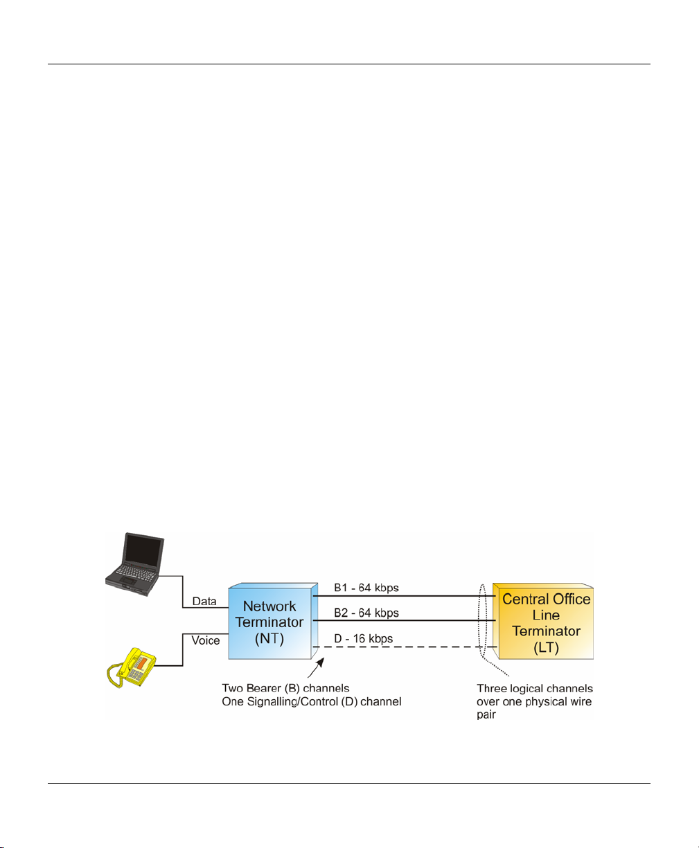
Integrated Services Digital Network - ISDN can be considered one of the first xDSL technologies
developed to simultaneously carry digital voice, data, and images over conventional copper cables. Basic
Rate ISDN is comprised of three logical channels operating over a single copper pair. Two bearer channels
(B Channels) carry voice, data, and images while the one D channel is used for signaling; commonly referred
to as 2B+D. Basic Rate ISDN offers speeds of up to 160 kbps symmetrically. ISDN is also available with a
Primary Rate Interface (PRI). The PRI interface offers data / voice / image transfers of up to 1.544 Mbps
(T1) over 23 B channels and one D channel or up to 2.048 Mbps (E1) over 30 B channels and one D
channel. Each channel in PRI operates at 64 kbps and is commonly referred to as 23B+D or 30B+D.
Figure 2A – Basic Rate ISDN Architecture
3
Page 16
VF / DSL Cable Qualifier
ISDN uses a 2B1Q line coding (2 Binary, 1 Quaternary) to represent information. 2B1Q maps two bits of
data into one quaternary symbol. (for example, onto four voltage levels at a regular clocking rate).
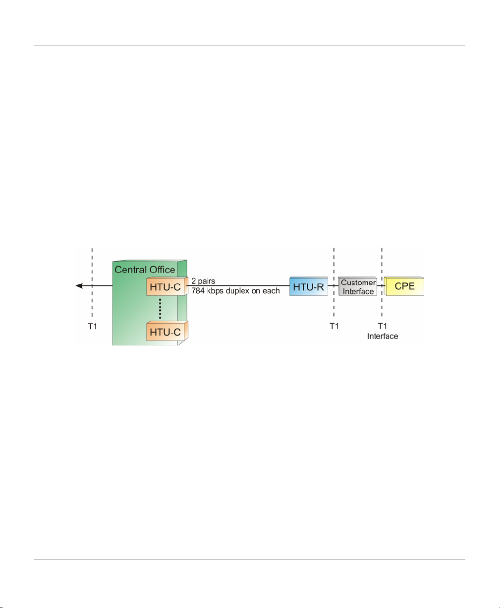
High bit-rate Digital Subscriber Line - HDSL is a symmetric DSL similar to T1 or E1 in that it delivers a bit
rate of 1.544 or 2.048 Mbps of bandwidth. Most systems use two copper twisted pairs, although some early
2.048 Mbps systems required three copper twisted pairs. HDSL is comprised of an HTU-C (HDSL
Transceiver Unit – CO) in the Central Office and a HTU-R (HDSL Transceiver Unit – Remote). Because
HDSL's speeds match those of T1 or E1 pipes, local telcos have been using the technology to provision
local access to T1 / E1 services whenever possible. It should also be noted that traditional T1 transmission
uses 2 copper pairs as well, so the transition from traditional T1 to HDSL T1 is fairly easy. HDSL's operating
range is more limited than that of ADSL since that after 15,000 feet signal repeaters are needed to extend
the service. Because HDSL requires two twisted pairs it is deployed primarily for businesses that require
PBX network connections, Virtual Private Networks (VPNs), Frame Relay Circuits, Internet Access, and
private data networks. HDSL is also preferred over traditional T1 because it is more spectrally compatible
with other technologies in the loop than AMI or B8ZS coded T1 or E1.
Figure 2B – HDSL Architecture
HDSL uses 2B1Q or CAP based line coding.
HDSL2 / SDSL– Similar to HDSL in operation but is capable of achieving HDSL rates over a single pair of
wires. This tends to limit transmission distances but it is still a successful technology. Most HDSL-2 systems
are based on non-standard, proprietary protocols. Little or no interoperability exists between vendors.
Asymmetric Digital Subscriber Line - ADSL provides delivery of high bit rate digital technology for
consumer based Internet access. ADSL delivers more bandwidth downstream (from the CO to the Customer
Premise) than upstream (Customer Premise to the CO). As most users view far more information than they
create ADSL is optimal. Downstream rates range from 256 kbits/s to 9 Mbps, while upstream bandwidth
ranges from 16 kbps to 640 kbps. ADSL transmissions may work at distances of more than 18,000 feet over
a single copper twisted pair, although it should be noted that only the lowest bit rates are available at these
lengths.
4
Page 17
CableSHARK P3 User Guide
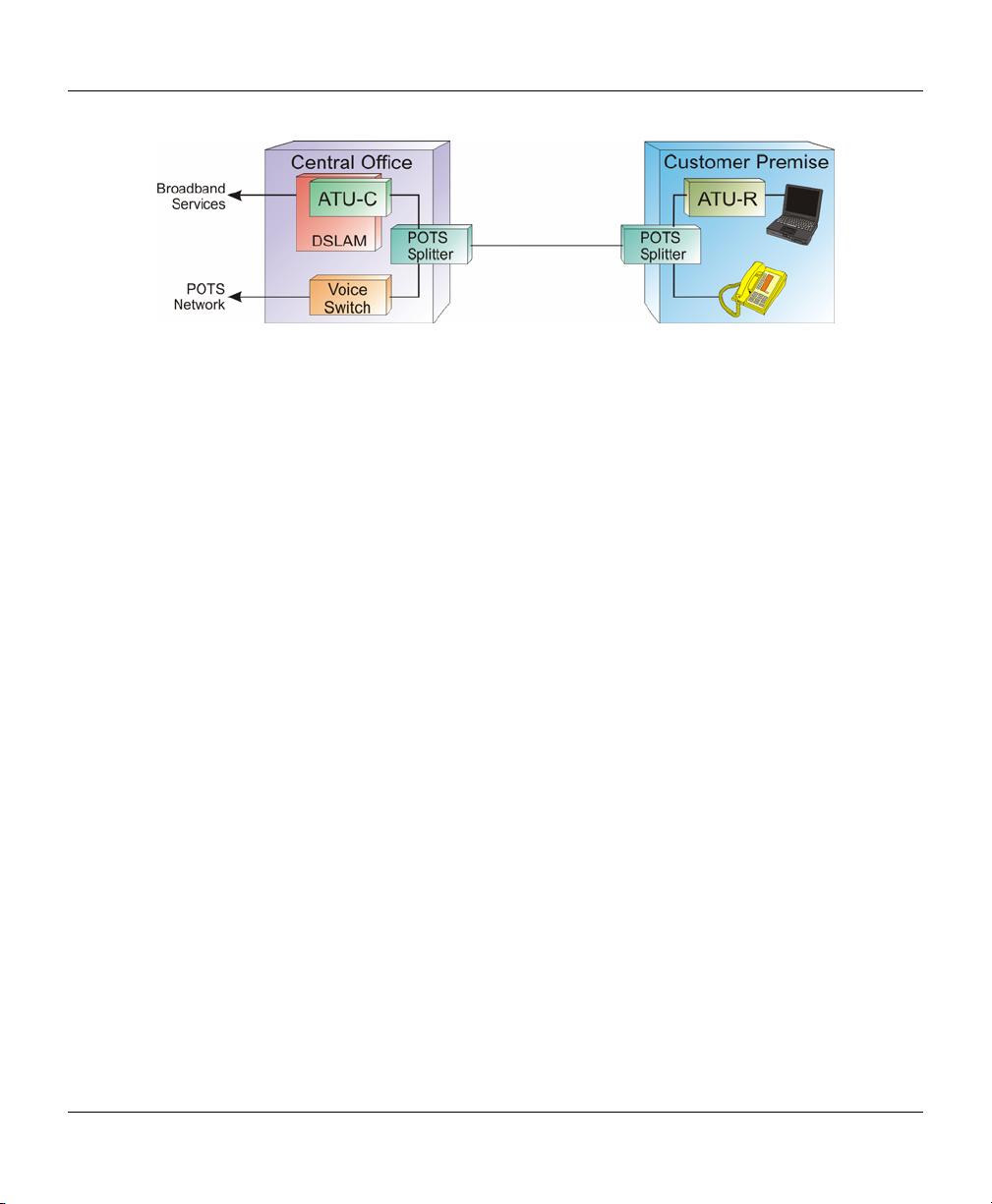
Figure 2C – ADSL Architecture
For service providers and customers alike, ADSL allows users to use their existing phone line to have both
high-speed Internet access as well as regular (including vital life-line) Plain Old Telephone Service (POTS).
ADSL signals are able to co-exist on the same loop with POTS service because they occupy a higher
frequency band than does POTS. ADSL typically will use the band of about 25 kHz to 1.104 MHz while
POTS uses 300 Hz to 3400 Hz. As a necessary precaution, a low pass filter is placed on the line to separate
ADSL signals from POTS signals. These so called POTS splitters or micro-filters must be in place for correct
operation. These small devices allow voice band frequencies to pass through to analog telephones while
keeping the high frequency signals of ADSL away from the phones. Likewise the input filters in ADSL
modems eliminate telephone signals from entering. In a similar fashion to ADSL and POTS on the same line,
ADSL can also co-exist with ISDN. However, since ISDN operates in the bandwidth up to 150 kHz, there are
fewer ADSL sub-channels that can be used resulting in a lower achievable data rate.
Two types of line coding exist for ADSL. An early scheme used a non-standards compliant CAP (Carrier-less
Amplitude / Phase Modulation) method. These days most ADSL DSLAMs and modems use the DMT
(Discrete Multi-Tone) technique. This book focuses on the DMT line coding as it is the DMT line code that is
recommended by ADSL standards bodies. These include ITU-T (G.992.1, G.992.2), ETSI, and ANSI /
Committee T1 (North America) (T1.413 Issue 2).
The DMT transmission scheme divides the frequency band from 0 Hz to 1.104 MHz into equally spaced subchannels or bins; this works out to 256 bins. Each bin occupies 4.3125 kHz of bandwidth. Since ADSL is
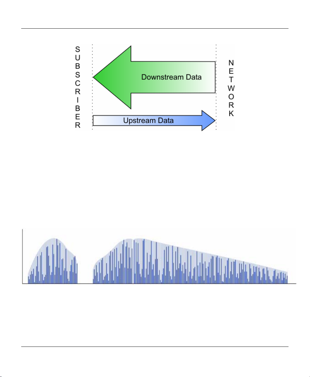
asymmetrical, the 1.104 MHz band is split once again into Upstream and Downstream bands. The Upstream
band carries information from the Customer Premise to the Network. The Downstream band carries
information from the Network to the Customer Premise.
5
Page 18
VF / DSL Cable Qualifier
Figure 2D – Asymmetric Nature of ADSL
There are actually 32 bins allocated for Upstream and up to 250 bins allocated for Downstream; 250 can
only be used with echo cancellation. For the most part, however, DMT implementations will use 218 bins for
Downstream. Guard bands that separate the POTS signals from the ADSL signals use some of the possible
carrier allocations. There is also a guard band between the upstream and downstream carriers.
ADSL uses 256 amplitude modulated carriers. The dark bars represent a “snapshot” of the modulation at any one point in
time. The light bars represent the maximum modulation state amplitude available for each carrier frequency. Notice how at
higher frequencies there are fewer available positions due to the diminishing signal to noise ratio.
Figure 2E – ADSL DMT
6
Page 19
CableSHARK P3 User Guide
DMT standards suggest that equipment can use up to 15 bits/bin to encode data per sub-channel. However,
using the maximum 15 bits/bin may result in the ADSL modems having to transmit at a higher power than
would be practical or allowed in a cable bundle. For the most part, ADSL makers have limited their designs
to use 13 or 14 bits/bin. This lowers the power transmitted between modems and maximizes the reach of
transmission without compromising potential data rates.
Rate adaptive Digital Subscriber Line - R-ADSL. This was an early name for a specific type of ADSL. These
days most ADSL modems are rate adaptive. They adjust the transmission speed dynamically to the length
and quality of the local loop. Most DSLAM network management systems allow the transmission speed to be
set or limited to a maximum bit rate.
G.Lite – A ‘lighter’ version of ADSL where downstream rates are limited to approx. 1.5 Mbps. G.Lite uses
128 bins rather than 256 (still using 4.3125 kHz sub-channel bandwidth) and only up to 8 bits/bin can be
encoded per sub-channel.
ADSL2 – ADSL2 offers data rates of up to 12 – 15 Mbps.
ADSL2+ – ADSL2+ offers data rates of up to 24 Mbps by increasing the frequency range to 2.2 MHz.
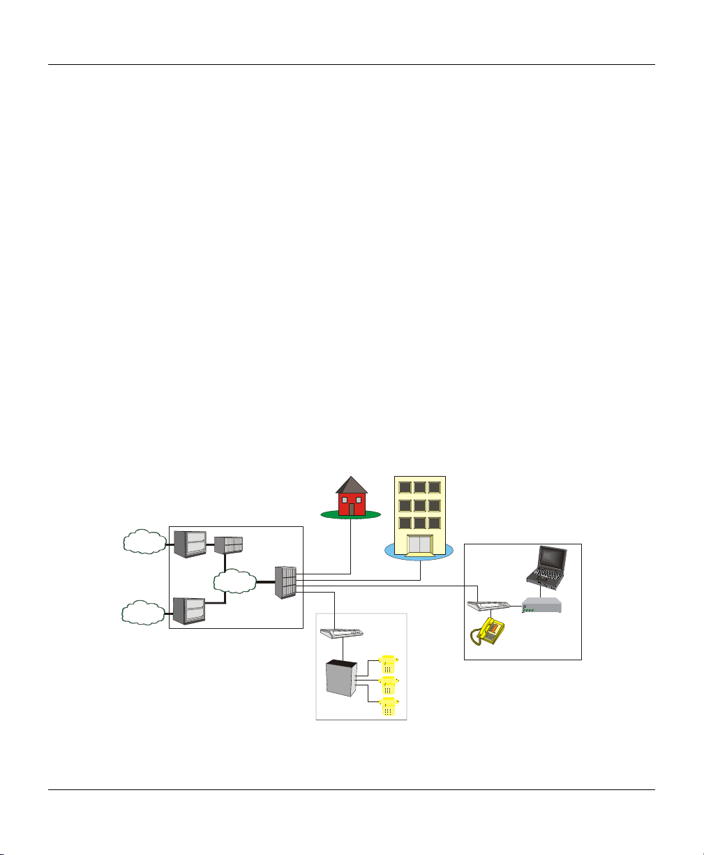
Symmetrical High-Speed Digital Subscriber Line – SHDSL is a technology that is similar to HDSL and
HDSL2. SHDSL operates over a single pair or 2 pairs of wire depending upon the application. For single pair
operation, SHDSL offers data rates from 192 kbps to 2.3 Mbps while two pair operation offers data rates
ranging from 384 kbps to 4.72 Mbps.
SME
PSTN
Internet
Voice
Switch
ISP
ATM
Backbone
Voice
Gateway
DSLAM
G.SHDSL
IAD
PBX
Figure 2F – SHDSL Architecture
G.SHDSL
Analog Phone
IAD
Router
PC
7
Page 20

VF / DSL Cable Qualifier
SHDSL is designed to be more of a business solution than a residential service due to its symmetry. It can
be used as a T1 / E1 replacement technology and is also well suited for VoDSL solutions.
SHDSL has been developed to be spectrally compatible with other technologies within bundles of local
loops. SHDSL owes this to the Trellis Coded Pulse Amplitude Modulation (TC-PAM) line coding. This coding
technique maximizes the use of the lower frequencies of available loop bandwidth thus avoiding higher
frequencies where signals are more susceptible to crosstalk.
The key benefit of xDSL is that by transmitting on an existing telephone line, there is no cable installation
costs to be incurred whereas if fibre optic cable were installed to achieve the higher bit rates, the cable
installation cost would be great.
8
Page 21
CableSHARK P3 User Guide
000
305
000
305
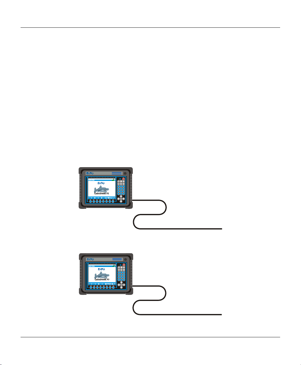
Section 3 Time Domain Reflectometry Overview
Time Domain Reflectometry (TDR) is a cable testing technique that is used to detect faults along power
transmission lines. Using this technique, voltage pulses are sent out over the line and voltage reflections
caused by cable abnormalities are monitored. Reflection times are measured from the reflection location on
the cable to the TDR device, which is attached to one end of the cable.
TDR technology can be compared to sonar. In sonar, a ship sends out an energy pulse through the water. If
an object, such a submarine, fish, ship, or underwater mountain is in close proximity, part or all of the pulse
is reflected back. The distance to the object can be calculated from a measurement of the time that it takes
for sound to travel through water.
In TDR, a pulse of energy is transmitted down a length of cable. When the energy pulse encounters the end
of the cable or a possible problem area (like a bridge tap or an open circuit), part or all of the energy is
reflected back to the TDR device. The TDR device measures the time it takes for the energy pulse to travel
down the cable and to be reflected. A calculation is made using the total pulse travel time and the Velocity
of Propagation (VOP) of the cable to determine the distance from the TDR equipment to the cable problem.
The VOP varies and depends on the cable size, material, etc.
VF/DSL Cable Qualifier
CableSHARK P3
Copyright Consultronics Limited 2000 - 2006
Software Version 3.86
AUTO
CABLE
AUTO
TESTS
TESTS
SETUP
F1 F2 F3 F4 F5 F6 F7 F8
EF
13:16:20
12
4
7
*
-
+
A
D
B
E
3
C
F
G
J
M
H
K
N
5
6
I
L
O
P
T
W
X
R
U
8
9
Y
S
V
Q
Z
0
#
RUN
STOP
1
ft /
m
Figure 3A - CableSHARK using TDR on a 1000 ft (305 m) cable
VF/DSL Cable Qualifier
CableSHARK P3
Copyright Consultronics Limited 2000 - 2006
Software Version 3.86
CABLE
AUTO
AUTO
TESTS
TESTS
SETUP
F1 F2 F3 F4 F5 F6 F7 F8
EF
13:16:20
12
G
H
4
I
P
R
7
S
*
-
+
A
D
B
E
3
C
F
J
M
K
N
5
6
L
O
T
W
U
X
8
9
V
Y
Q
Z
0
#
RUN
STOP
1
ft /
m
9
Page 22
VF / DSL Cable Qualifier
Figure 3B - A Pulse Reflection indicates a load coil at 500 ft (152 m)
TDR’s can use various methods of testing to determine the location of problems along the length of the cable
under test. Impedance is a major player. The TDR equipment looks for a change in impedance which could
be caused by improper installation, cable damage (caused by water, etc.), end of cable, and a bridged tap.
The magnitude of the impedance changes determines the amplitude of the reflection.
There is a direct relationship between voltage pulse width sent down the cable and the distance that it travels
along the cable. The smaller the pulse, the less the energy it contains, and therefore, the distance that it
travels along the cable is less. Voltage pulses of greater width travel further distances. When using this
technique, it is best to start testing with voltage pulse of small width and to work up to pulses of larger width.
Voltage pulse width is typically measured in nanoseconds.
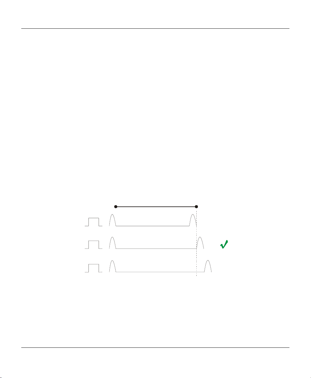
Several factors affect the operation of TDR devices and the results they display. As mentioned earlier in this
section, VOP, or Velocity of Propagation is a very important value to know in determining the distance to an
impairment. VOP represents the speed at which energy travels through a medium. In the case of xDSL, the
medium is a copper twisted pair. VOP is measured as a percentage of the speed of light in a vacuum. Users
of TDR’s may see the VOP expressed as 0.66 or 66%; both are acceptable.
VOP is an extremely important parameter. It must be correct, as any deviations may give the user false
readings. Most cable manufactures will indicate the VOP for their particular cable. The VOP depends upon
cable diameter, material out of which the cable is made, and on impurities in this material.
1000 ft (300 m)
VOP = 62%
VOP = 64%
X
X
VOP = 66%
Figure 3C – Selecting the correct VOP means knowing the correct distance
When using the TDR technique, the cable under test should not be terminated. Cables that are terminated
absorb most or all of the energy pulse sent down the cable which, in turn, means that no energy is reflected
back to the TDR device. When using the CableSHARK’s TDR function, ensure that the far end of the cable
is configured as an OPEN or SHORT circuit.
10
Page 23
CableSHARK P3 User Guide
A
Not all cables are the same, hence the variations in VOP. Conversely, not all local loops are the same.
Some local loops are longer than others and susceptibility to noisy environments varies. All signals on these
loops, regardless of cable length or environment, are subject to attenuation. Attenuation affects both
transmitted and reflected signals and, if the signal-to-noise ratio is low enough, impairments may not be
identifiable. To overcome the affects of attenuation, use a larger pulse width (more energy) to locate
impairments or take measure from both ends of the cable.
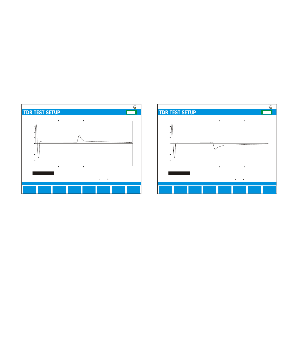
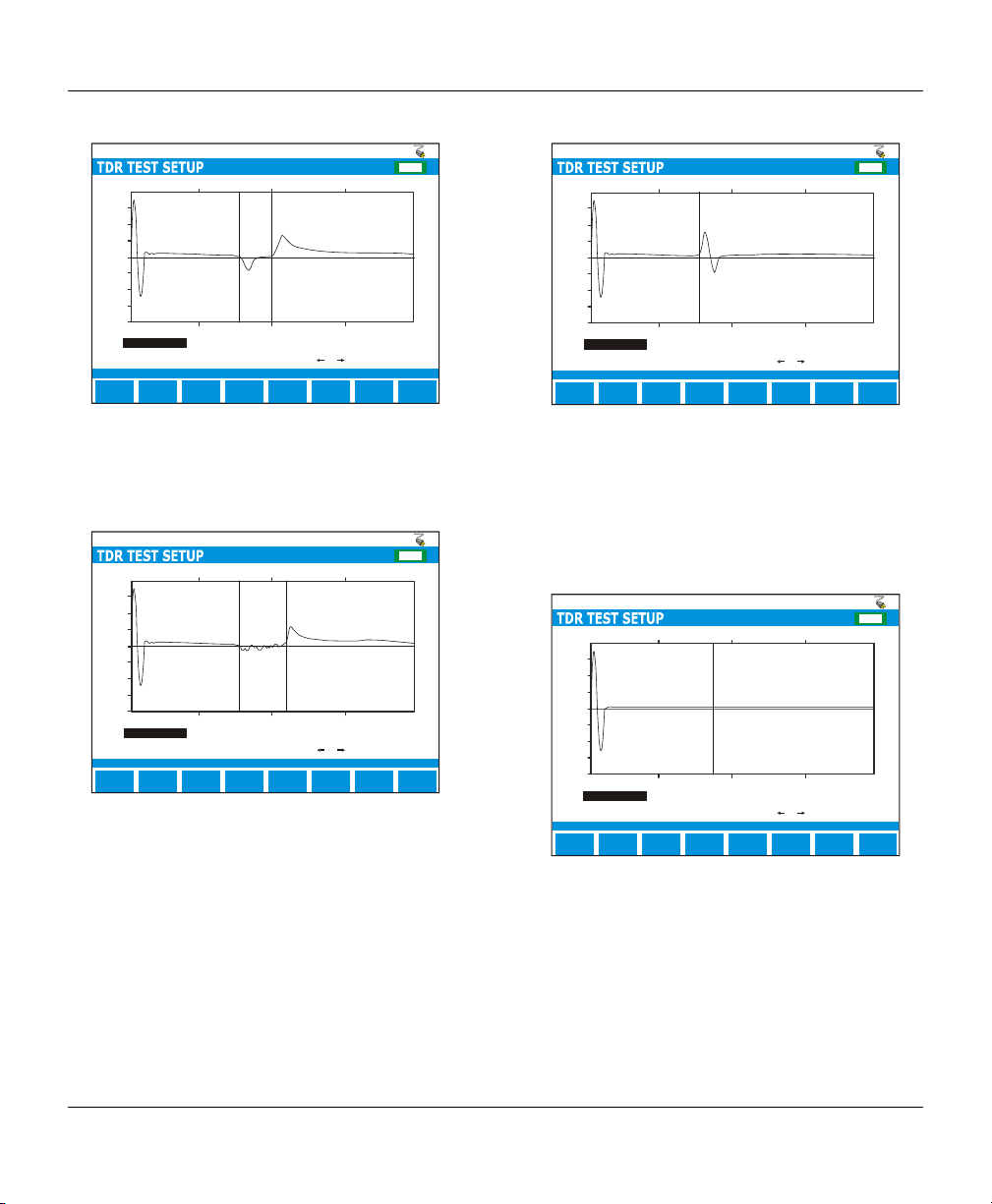
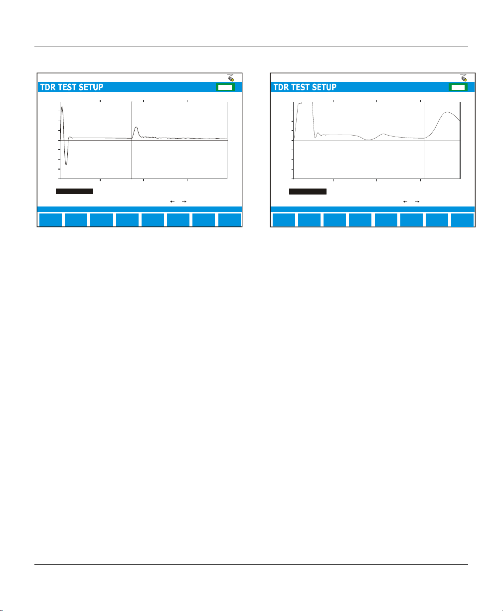
The following diagrams depict possible TDR traces and their causes.
EF
CHG
1.000
0.750
0.500
0.250
0.000
-0.250
-0.500
-0.750
-1.000
0.0 1250.0 2500.0 5000.03750.0
Cursor position =
Cursor position =
Marker position =
Cursor / Marker Delta =
Reflections at ft(dBRL): 1998. 7 (33.8+)
ZOOM IN
VERT
ZOOM IN
HORIZ
1998.7
0
1998.7
ft
SELECT
MARKER
Pulse Width:ft
Press or to move cursor
MORE
300 ns
AUTO
REPEAT
MAIN
MENU
The above figure depicts an OPEN circuit or a
high impedance fault. Depending upon the size of
the reflected pulse, the OPEN could be an partial
(small pulse) or complete (large pulse) open
circuit. Of course, the length of the cable,
attenuation on the line, and the size of the
outgoing pulse will play a big role in determining
the reflection.
1.000
0.750
0.500
0.250
0.000
-0.250
-0.500
-0.750
-1.000
0.0 1250.0 2500.0 5000.03750.0
Cursor position =
Cursor position =
Marker position =
Cursor / Marker Delta =
Reflections at ft(dBRL): 19 98.7 (33.8+)
ZOOM IN
VERT
ZOOM IN
HORIZ
1998.7
0
1998.7
Pulse Width:ft
ft
Press or to move cursor
SELECT
MORE
MARKER
The above figure depicts a SHORT circuit or a
low impedance fault. Depending upon the size of
the reflected pulse, the SHORT could be an
partial (small pulse) or complete (large pulse)
short circuit. Of course, the length of the cable,
attenuation on the line, and the size of the
outgoing pulse will play a big role in determining
the reflection.
EF
CHG
300 ns
MAIN
UTO
MENU
REPEAT
11
Page 24
VF / DSL Cable Qualifier
A
A
A
A
EF
CHG
1.000
0.750
0.500
0.250
0.000
-0.250
-0.500
-0.750
-1.000
0.0 1250.0 2500.0 5000.03750.0
Cursor position =
Cursor position =
Marker position =
Cursor / Marker Delta =
Reflections at ft(dBRL ): 2195.3 (24.2-), 2500.0 (32.1+)
ZOOM IN
VERT
ZOOM IN
HORIZ
2500.0
2195.3
304.7
ft
SELECT
MARKER
Pulse Width:ft
Press or to move cursor
MORE
300 ns
UTO
REPEAT
MAIN
MENU
The above figure depicts a bridge tap. The bridge
tap is composed of a negative pulse (start of the
bridged tap) and a positive pulse (end of the
bridged tap).
EF
CHG
1.000
0.750
0.500
0.250
0.000
-0.250
-0.500
-0.750
-1.000
0.0 1250.0 2500.0 5000.03750.0
Cursor position =
Cursor position =
Marker position =
Cursor / Marker Delta =
Reflections at ft(dBRL ): 2719.1 (32.1+)
ZOOM IN
VERT
ZOOM IN
HORIZ
2719.1
2195.3
523.8
ft
SELECT
MARKER
Pulse Width:ft
Press or to move cursor
MORE
300 ns
UTO
REPEAT
MAIN
MENU
The above figure depicts a water soaked cable
with a OPEN circuit. The water section could
have appear anywhere along the cable.
Generally, a ‘noisy’ reflection could mean water.
EF
CHG
1.000
0.750
0.500
0.250
0.000
-0.250
-0.500
-0.750
-1.000
0.0 1250.0 2500.0 5000.03750.0
Cursor position =
Cursor position =
Marker position =
Cursor / Marker Delta =
Reflections at ft(dBRL ): 2195.3 (24.2+)
ZOOM IN
VERT
ZOOM IN
HORIZ
2195.3
0
2195.3
ft
SELECT
MARKER
Pulse Width:ft
Press or to move cursor
MORE
300 ns
UTO
REPEAT
MAIN
MENU
This figure shows a HIGH RESISTANCE JOINT
or SPLICE. This is composed of a high
impedance reflection followed by a low
impedance reflection. Generally, the better the
splice, the smaller the reflection. A large
reflection, as denoted above, would signify a poor
splice.
EF
CHG
1.000
0.750
0.500
0.250
0.000
-0.250
-0.500
-0.750
-1.000
0.0 1250.0 2500.0 5000.03750.0
Cursor position =
Cursor position =
Marker position =
Cursor / Marker Delta =
Reflections at ft(dBRL ): 1998.7 (33.8+)
ZOOM IN
VERT
ZOOM IN
HORIZ
1998.7
0
1998.7
ft
SELECT
MARKER
Pulse Width:ft
Press or to move cursor
MORE
300 ns
UTO
REPEAT
MAIN
MENU
This figure depicts a terminated cable. The
terminated cable absorbs the send pulse and
causes no reflection. For the purposes of TDR
testing, it is best to use an un-terminated cable to
ensure a reflection is send to the CableSHARK.
12
Page 25
EF
A
A
CHG
1.000
0.750
0.500
0.250
0.000
-0.250
-0.500
-0.750
-1.000
0.0 2500.0 5000.0 10000.07500.0
Cursor position =
Cursor position =
Marker position =
Cursor / Marker Delta =
Reflections at ft(dBRL): 1998. 7 (33.8+)
ZOOM IN
VERT
ZOOM IN
HORIZ
2995.2
0
2995.2
ft
SELECT
MARKER
Pulse Width:ft
Press or to move cursor
MORE
300 ns
UTO
REPEAT
MAIN
MENU
This figure shows a typical response from a
LOAD COIL. It resembles a complete OPEN.
Although LOAD COILS are placed at specific
intervals, a TDR will typically not ‘see’ past the
first LOAD COIL.
CableSHARK P3 User Guide
EF
CHG
1.000
0.750
0.500
0.250
0.000
-0.250
-0.500
-0.750
-1.000
0.0 1250.0 2500.0 5000.03750.0
Cursor position =
Cursor position =
Marker position =
Cursor / Marker Delta =
Reflections at ft(dBRL): 39 99.4 (24.2+)
ZOOM IN
VERT
ZOOM IN
HORIZ
3999.4
0
3999.4
ft
SELECT
MARKER
Pulse Width:ft
Press or to move cursor
MORE
300 ns
UTO
REPEAT
MAIN
MENU
This figure shows a test run through a POTS
Splitter, ending in a complete OPEN circuit.
13
Page 26

VF / DSL Cable Qualifier
14
Page 27
CableSHARK P3 User Guide
Section 4 Physical Features and Power Supply
4.1 Physical Features of the CableSHARK
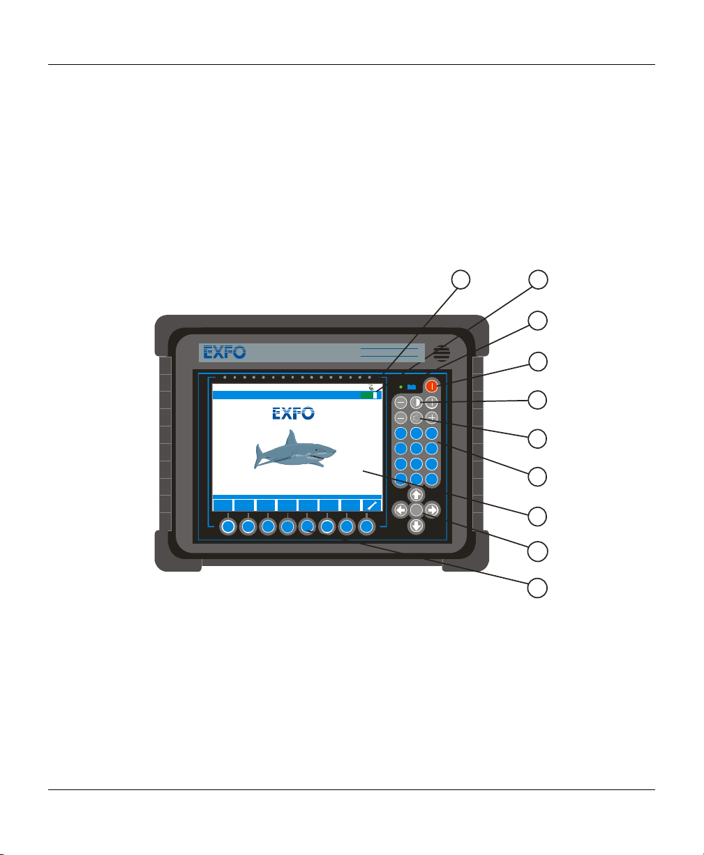
4.1.1 The Front Panel
The illustration below shows the front panel features of the CableSHARK. These features are described
following the illustration.
1
2
3
MAIN MENU
CABLE
AUTO
TESTS
TESTS
F1 F2 F3 F4 F5 F6 F7 F8
Figure 4.1.1A - CableSHARK Front Panel
1. AC Mains Plug Symbol
This symbol indicates if the CableSHARK is receiving power from an AC mains supply. There will
be no symbol if power is disconnected from the unit.
2. Battery Status Indicator
Indicates status of battery. Battery Gas Gauge will move between E and F. E represents EMPTY
(battery needs recharging) and F represents FULL (battery is fully recharged). A percentage will
appear indicating the amount of battery capacity left.
CableSHARK P3
CableSHARK P3
Co pyrigh t Con sult ronic s Lim ited 20 00 - 200 6
AUTO
SETUP
Software Version 3.86
RESPON D.
MODE
VF/DSL Cable Qualifier
EF
13:16:20
RECALL
RESULTS
-
+
12
G
H
4
5
I
P
R
7
8
S
0
*
RUN
STOP
4
5
A
D
B
E
3
C
F
J
M
K
N
6
L
O
T
W
U
X
9
V
Y
Q
Z
#
6
7
8
9
10
15
Page 28

VF / DSL Cable Qualifier
3. Power On LED
This LED indicates the ON/Off status of the CableSHARK. It also shows the status of the internal
battery and the condition of the charging circuit.
4. Power On/Off Button
This push button switch turns the instrument on or off.
5. Contrast Controls
Adjusts the contrast of the LCD display. The contrast required will depend on the lighting conditions
of the environment. Battery life will be enhanced if the LCD Backlighting is turned off when not
needed (i.e. when there is sufficient ambient light). Press the
on and off.
symbol to toggle the backlight
6. Volume Controls
Not used.
7. Integral Keypad
Used for entering alphanumeric values, names, and other information.
8. LCD Display
640 x 480 pixel backlit LCD display. The CableSHARK can be ordered with either a monochrome
display or a colour display.
9. Cursor Pad
The arrow keys move the cursor through the displayed menu options. A Run/Stop button is located
in the center of the cursor pad, which is used to start and stop tests.
10. Function Buttons
Used in conjunction with the screen menu, the eight buttons provide the majority of the functions
that control the CableSHARK.
16
Page 29
CableSHARK P3 User Guide
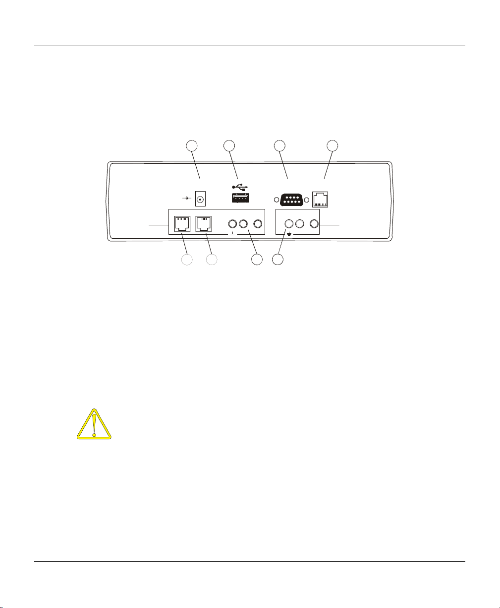
4.1.2 The Rear Panel
The illustration below shows the back panel features of the latest CableSHARK. Each item is described
following the illustration.
12
3
4
2 WIRE
LINE
Tx / Rx
18 V
DC IN
-
+
RJ11RJ45
5 6
GND GND
RING TIP
RS232/V.24
ETHERNET
SERIAL
RING TIP
Rx (AUX.)
8
7
Figure 4.1.2A – The CableSHARK’s Rear Panel
1. Power Connector for AC Adapter
Provides connection of the CableSHARK to the power mains via the AC adapter provided with the
unit. The internal battery is automatically charged once the instrument is plugged in, even when
the instrument is switched off.
2. Universal Serial Bus (USB) Series A Receptacle
This USB connection provides the user with the ability to save results to a USB Memory. Users
can save results to the optional 256 MB USB Memory available from EXFO. Users can also
upgrade the CableSHARK via the USB port using the USB Memory.
The CableSHARK works with the following other USB Memory devices:
• Universal Smart Drive USB1.1 (64 Meg)
• Universal Smart Drive USB1.1 (32 Meg)
• Sandisk cruzer mini USB2.0 (32 Meg)
• USB 007 USB1.1 (32 Meg)
• Shikatronics Flash Drive USB2.0 (32 Meg)
• Kingston USB1.1 (32 Meg)
• Intelligent Stick USB1.1 (32 Meg)
17
Page 30

VF / DSL Cable Qualifier
3. Serial Communication Port (Male)
The 9-pin connector provides serial communication with a computer. The CableSHARK can
download its results to a terminal program or be remote controlled via the optional Microsoft
Windows® based Visi-SHARK program. This port is also used to upgrade the software version
resident within the CableSHARK.
4. Ethernet 10BaseT Port
The Ethernet connector provides high-speed communication with a computer. The CableSHARK
can download its results to a terminal program or be remote controlled via the optional Microsoft
Windows® based Visi-SHARK program. This port is also used to upgrade the software version
resident within the CableSHARK.. Users will have to define their IP address, Gateway address
and subnet mask under System Setup.
5. RJ-45 connector
RJ-45 connector for connection to the line. Supports 2 wire TX and RX functionality.
6. RJ-11 connector
RJ-11 connector for connection to the line. Supports 2 wire TX and RX functionality.
7. 2 Wire TX & RX 3 Pin Connector
3 Pin connector for connection to the line and acting as a transmitter and receiver. This connector
can be used in conjunction with the Rx (AUX.) connector and acts as the transmitter for 4 Wire
implementations.
8. Rx (AUX.) 3 Pin Connector
3 Pin connector for connection to the line and acting as a receiver (RX) only. This allows access
to the 4 wire features of the CableSHARK . Features Tip, Ring, and Ground connections. The Rx
(AUX) connector is also used for the “Good Pair” connection in RFL (Yellow and Green telco clip
cable).
4.1.3 The Serial Interface Connection
The serial interface is used to connect the CableSHARK to a PC terminal. The connector for this is a male 9
pin D-type on the rear panel. When connecting to your equipment, a 9 pin “D” to 25 pin “D” type cable or
conversion adapter may be required. The serial interface is compatible with the EIA RS-232 and ITU V.24
specifications. The pin assignments for this are as follows:
18
Page 31

CableSHARK P3 User Guide
n
PIN MNEMONIC DIRECTION DESCRIPTION
1 N.C. ----- Not Connected
2 RD TO CableSHARK RECEIVED DATA
3 TD FROM CableSHARK TRANSMITTED DATA
4 DTR FROM CableSHARK DATA TERMINAL READY
5 SG COMMON SIGNAL GROUND
6 DSR TO CableSHARK DATA SET READY
7 RTS FROM CableSHARK REQUEST TO SEND
8 CTS TO CableSHARK CLEAR TO SEND
9 N.C. ----- Not Connected
Te rm i na l
Adapter Connectio
End
2
2
3
3
4
4
5
5
6
6
7
7
8
8
2
3
4
5
6
7
8
CableSHARK
End
2
3
4
5
6
7
8
Figure 4.1.3A - Serial Interface Connection
The connector is configured as a DTE (Data Terminal Equipment). It is recommended that the cable length
be 50 feet or less to reduce the possibility of errors from signal distortion. Also, the connectors should be
secured with the proper screws to enable reliable operation. All necessary serial cables should be double
shielded where appropriate.
If the unit is connected to a terminal or computer, a Null Modem cable is required. This null modem cable is
available from EXFO and should be ordered with the CableSHARK. Null modem cables are available in
various configurations. The configuration on Figure 4.1.3A above gives the pin arrangement of a typical null
modem cable.
4.1.4 The Ethernet 10BaseT Connection
The Ethernet 10BaseT port is used to connect the CableSHARK to a PC terminal via a LAN or the Internet.
The connector for this is a female RJ-45 connector on the rear panel of the CableSHARK. When connecting
to your equipment, a crossover cable or straight cable can be used (defined below) depending upon the
network infrastructure. The Ethernet interface is compatible with the TIA/EIA T568A and TIA/EIA T568B
specifications. The pin assignments for this are as follows:
19
Page 32

VF / DSL Cable Qualifier
8
8
TIA/EIA T568A
* use for connections between CableSHARK and
the network.
Green
Pair 3
Orange
Pair 2
Blue
Pair 1
Brown
Pair 4
TIA/EIA T568B
* use for connections between CableSHARK and a
PC.
CableSHARK
End
1
TX+
2
TX-
RX+
3
4
5
6
RX-
7
Green / White
Green
Orange / White
Blue
Blue / White
Orange
Brown / White
Brown
Network
(non-PC)
1
2
3
4
5
6
Figure 4.1.4A - Ethernet “Straight” Connection
RX+
RX-
TX+
TX-
7
CableSHARK
TX+
TX-
RX+
RX-
Figure 4.1.4B - Ethernet “Crossover” Connection
The maximum length for 10BaseT specifications is 300 ft (100 m).
Contact your Network Administrator if you have any questions on network cabling.
End
1
2
3
4
5
6
7
8
G
G
r
Blue
r
O
Brown
Orange
Pair 2
r
e
e
n
e
e
n
e
g
n
a
/
W
Green
Pair 3
Blue
Pair 1
h
i
t
e
Blue / Wh ite
Brown / Whi te
Brown
Pair 4
PC
End
e
t
i
h
W
1
/
e
g
n
a
r
O
n
a
r
O
TX+
e
2
g
TX-
3
RX+
4
5
G
r
e
e
n
6
RX-
7
8
20
Page 33

CableSHARK P3 User Guide
4.2 Powering the CableSHARK
4.2.1 The CableSHARK’s External Mains Adapter
The CableSHARK gets power from an external mains adapter which can operate at voltages from 100 V.A.C
to 240 V.A.C and frequencies from 50 to 60 Hz. The AC mains adapter is automatic and requires no
selection for different line voltages and frequencies. The CableSHARK also has an internal NiMH
rechargeable battery.
Although this rechargeable NiMH battery was fully charged before it left the factory, it
is recommended that you fully charge the CableSHARK before using it for the first
time in case there has been a long time delay between the time the unit left our
factory and the time you first use the CableSHARK.
To power the CableSHARK with the adapter, first locate the power connector at the rear of the instrument.
Plug the adapter to the AC mains and the CableSHARK. Only the supplied Power Adapter should be used
(EXFO Part Reference CSK-ACx3). Spare or replacement Power Adapters can be ordered from your local
EXFO distributor.
The CableSHARK is switched on by pressing the Power button (located on the top right of the unit) for 2
seconds. The CableSHARK will cycle through its Self-test sequence and will indicate any fault conditions.
The CableSHARK is switched off by pressing the Power button for 2 seconds. It is recommended that the
CableSHARK be switched off when not in use to preserve battery charge.
When the CableSHARK is connected to AC mains power, its internal battery will be automatically charged
and charging will occur whether the CableSHARK is switched On or Off. A full charge cycle takes between 2
and 4 hours, during which time the unit may be used. The CableSHARK will operate from the internal
battery for up to 3.5 hours of typical use on a full charge with the standard Monochrome display. Note that
the battery will slowly discharge over time even when the instrument is OFF. To charge the CableSHARK
simply connect it to AC power using the AC adapter supplied.
4.2.2 The CableSHARK’s Internal Battery
The CableSHARK uses a Nickel Metal Hydride (NiMH) rechargeable battery. These cells are particularly
well suited for deep cycle and deep discharge applications.
CAUTION: ONLY USE BATTERIES SUPPLIED BY EXFO (EXFO Part Reference CSKBATT2). Return Old Batteries to EXFO for recycling. Nickel Metal Hydride Cells are
maintenance-free and are non-spillable, and therefore can be operated in any position.
They should be kept clean and dry during use and operation.
21
Page 34

VF / DSL Cable Qualifier
CAUTION: Danger of explosion if battery is incorrectly replaced. Replace only with same
or equivalent type recommended by the manufacturer. Dispose of used batteries
according to the manufacture’s instructions.
Charging: It is recommended that charging of the battery be performed between 0 to +40
Storage and Self-discharge: It is recommended that storage of the battery is done between –10 to +50
0
C.
0
C.
Long-term storage has no permanent effect on battery capacity. Losses in capacity due to self-discharge
are reversible. After Long-term storage (e.g. more than one year at room temperature) up to three full cycles
may be necessary to obtain full capacity.
Repeated charging, operating and storage in extreme temperatures may effect battery life.
NOTE: Should the battery be subjected to a deep discharge, the unit may have to be
plugged in to AC mains for about 2 minutes before the unit can be turned on.
4.2.2.1 Replacing the CableSHARK’S Internal Battery
The Battery is user-replaceable without the need for re-calibration. Extra batteries are available from your
EXFO representative (CSK-BATT2). Accompanying the battery will be instructions for replacing and
charging. The CableSHARK has been designed such that the user can change the battery easily with very
few tools. Extra batteries are available from your EXFO representative. To change the battery, locate the
battery compartment door on the underside of the unit.
Please note that any stored data in non-volatile RAM will not be lost by changing the
rechargeable battery.
After removing the two slotted screws from the battery cover, the cover must be carefully pried; with the
slotted screwdriver ; to loosen and release the sealing tape between the cover and the battery. Note: The
battery is friction fitted into the battery compartment. Once the battery cover has been removed, the battery
can be removed from the battery compartment by placing ones hand over the battery, turning the unit so the
display is facing upwards and then gently tap the CableSHARK against the same hand. Once the battery is
freed from its compartment, the black connector with the flying clip must be removed from the small slot in
the battery compartment. The black clip is then pressed to release the male and female connector.
To reinstall the battery, the mating connectors are latched in place with the retaining clip. Carefully insert the
black connector into the side slot of the battery compartment on a 45 degree angle with the mating clip
22
Page 35

CableSHARK P3 User Guide
positioned to the inside of the battery compartment. In some CableSHARK’s, this may require some
maneuvering to position the connector in place. The excess battery wire should be carefully inserted into the
side slot of the battery compartment. Install the battery in the compartment; replace the battery cover and
tighten the two slotted screws in place.
Return the old battery to EXFO for recycling. Immediately, (same day) plug the CableSHARK into the mains
so that the battery will be charged. The power LED should be green at this time. Charge the unit until fully
charged.
4.2.3 The LED Power Status Indicator
The CableSHARK’s dual color Power Status LED is designed to indicate the instrument's power status:
State Explanation
Bright Green Running on mains power, the battery is fully charged
Dull Green Running on the battery
Flashing Green The battery is charging
Red The battery is exhausted or there is a malfunction in the battery
Note: The LED can also illuminate so it is orange in colour.
Orange Both the red and green LED’s will illuminate (looks orange) to indicate
the unit is in Responder mode.
23
Page 36

VF / DSL Cable Qualifier
24
Page 37

CableSHARK P3 User Guide
Section 5 General Operating Instructions
The CableSHARK is easy to operate, with a simple to understand top panel consisting of a large 640 x 480
graphic Liquid Crystal Display, eight function buttons, menu control buttons, alphanumeric keypad, contrast
controls, easy access connectors at the rear, and a power on/off button.
To begin operation, press the power button for 2 seconds
“MAIN MENU” after a brief self-test sequence. The Self-test sequence will take less than 60 seconds to
complete (typically 30 seconds).
Note: All test leads can be purchased from EXFO. These twisted pair cables have been manufactured to
ensure maximum protection against radio frequency and electromagnetic radiation. If any of the cables used
with the CableSHARK become lost or broken, please contact EXFO or your local representative for
replacements. If time does not permit, use only 24 AWG twisted pair cable providing the twist is maintained.
These cables must be less than 6 ft (2m) to prevent any noise to be induced upon the test.
5.1 Self Tests and Resetting the CableSHARK
5.1.1 Self Tests
The CableSHARK is equipped with a self-test feature. The function is performed each time the unit is turned
on. To repeat a self-test, turn the instrument off, wait a few seconds and then turn it back on. There are
actually two self tests (calibration tests) that can be performed at start-up. The ‘warm’ self test is a quick
calibration that is performed at start-up. A full calibration is performed once the unit is reset or when the
start-up program detects any variations of hardware and/or environmental conditions.
If any of the circuits are defective, the screen will display a list of the faults. If one or more of these
messages appear on the screen, ensure the unit is within the operating conditions specified in this manual.
Condensation and/or temperature extremes may cause failure conditions. If the failure persists, the unit
should be serviced by EXFO or a certified EXFO repair and serving facility to enable reliable operation.
to turn the unit on and the screen will display the
5.1.2 Resetting the CableSHARK
The CableSHARK comes with a reset feature so that the user can reset all settings to their factory defaults.
To reset the CableSHARK, enable the Set Factory Defaults option under the System Setup. Once enabled,
the CableSHARK will be reset to its default settings and commence normal startup procedures.
Any changes made by the user to the settings of a test will revert back to its factory default settings in most
cases.
25
Page 38

VF / DSL Cable Qualifier
5.2 Connecting the CableSHARK to the Line
The CableSHARK P3 VF/DSL Cable Qualifier is used to qualify copper telco cable of the local loop to see if
it is suitable to carry Digital Subscriber Line (DSL) technologies. The CableSHARK can be configured to
perform Single-Ended (one unit) and End-to-End (two units) tests. The following sections will describe how to
connect the CableSHARK P3 VF/DSL Cable Qualifier to the line for each of these tests.
5.2.1 Test Cable and Connector Requirements
The CableSHARK can be ordered with an optional Siemens (CF) connector to three colour coded Telco
clips. The CF connector inserts into the CableSHARK CF jack on the rear panel, while the three telco clips
are color coded for Tip, Ring, and Ground and are for use with the service provider’s equipment. The
following is a diagram showing the cable:
TIP - BLACK
26
TIP
RING
GND
TIP
RING
GND
Figure 5.2.1A – Optional “All Purpose” Test Cable
Figure 5.2.1B – Optional RFL Test Cable
RING - RED
GND - GREEN
TIP - YELLOW
RING - BLUE
GND - GREEN
Page 39

CableSHARK P3 User Guide
e
5.2.2 Single-Ended Testing
The CableSHARK can perform Single-Ended tests on a copper telco cable to see if the line can carry DSL
technologies such as ADSL2+, SHDSL, and VDSL. Frequency Response (Single-Ended selected), Time
Domain Reflectometry, Digital MultiMeter, Power Spectral Density and Impulse Noise tests are examples of
single-ended tests with the CableSHARK. For single-ended tests, ensure that the cable to be tested is not
match-terminated at the far end. The far end should be an open or short circuit for best results. The
CableSHARK can operate, using most measurements, if there is an active ADSL CPE modem, subscriber
telephone, POTS Splitter/microfilter, active DSLAM, or Class 5 Voice Switch at the far end however these
devices may affect the measurements. For optimal results, measure the cable from both ends using the
included Single-Ended tests. This will help compensate for any irregularities caused by cable type, cable size
and any impairments that can occur or are resident on the line at the time of testing.
Note: Single-Ended testing can only give a partial picture of cable quality if testing is
done from one end only. For an accurate picture of cable quality, single-ended
testing should be done from both ends of a cable. This is a benefit to the user since
they will get a total view of cable quality plus the added bonus of increasing their test
distances.
Figure 5.2.2A shows the CableSHARK connected to the line. Notice that at the Central Office end, the cable
is not match terminated. Testing from the Central Office to Subscriber can also be completed this way.
Appendix A - Ideal Cable Results, will show what an ideal cable frequency response should resemble.
CableSHARK P3
CableSHARK P3
Copyright Consultronics Limited 2000 - 2006
Copyright Consultronics Limited 2000 - 2006
Software Version 3.86
Software Version 3.86
CABLE
AUTO
AUTO
CABLE
AUTO
AUTO
TESTS
TESTS
SETUP
TESTS
TESTS
SETUP
F1 F2 F3 F4 F5 F6 F7 F8
F1 F2 F3 F4 F5 F6 F7 F8
CableSHARK
VF/DSL Cable Qualifier
VF/DSL Cable Qualifier
EF
EF
13:16:20
13:16:20
12
12
4
4
7
7
*
*
OPEN or
SHORTED
CABLE
-
+
+
A
D
A
D
B
E
B
E
3
3
C
F
C
F
G
J
G
J
M
M
N
N
H
K
H
K
5
5
6
6
O
O
I
L
I
L
P
T
P
T
W
W
X
X
R
U
R
U
8
8
9
9
S
V
S
V
Y
Y
Q
Q
Z
Z
0
0
#
#
RUN
RUN
STOP
STOP
ADSL
CPE
Modem
(active)
Telephon
(On hook)
27
Page 40

VF / DSL Cable Qualifier
A
A
VF/DSL Cable Qualifier
DSLAM
CableSHARK P3
Copyright Consultronics Limited 2000 - 2006
Software Version 3.86
CABLE
AUTO
AUTO
TESTS
TESTS
SETUP
F1 F2 F3 F4 F5 F6 F7 F8
CableSHARK
EF
13:16:20
12
4
7
-
+
D
B
E
3
C
F
G
J
M
H
K
N
5
6
I
L
O
P
T
W
R
U
X
8
9
S
V
Y
Q
Z
0
#
*
RUN
STOP
Figure 5.2.2A - Examples of Circuit where Single Ended Measurements can be used
5.2.3 End-to-End Testing
End-to-End testing allows two CableSHARK’s to connect to the same line to perform a variety of tests (as
shown in Figure 5.2.3A). Tests include End-to-End Frequency Response, DMT tests, and Load Coil
Detection. A CableSHARK at the Far End is the Tx unit, which is running in Remote Responder Mode. It
responds to all End-to-End test requests from the Rx unit as a controller and sends signals for the requested
test down the line to the Rx unit, which in turn converts the signal and analyzes the results. The Rx unit is
the one that analyzes and displays the information.
Cable SHARK P3
A World of G ood for You r Network s
SYSTEM
CABLE
DMM
RECALL
SETUP
TESTS
TESTS
RESULTS
F1 F2 F3 F4 F5 F6 F7 F8
EF
CHG
13:16:20
xDSL Cable Qualifier
12
4
7
*
+-
CableSHARK P3
A
D
B
E
3
C
F
G
J
M
H
K
N
5
6
I
L
O
P
T
W
R
U
X
8
9
S
V
Y
Q
0
Z
#
RUN
STOP
F
Responder is waitin g f or a r emote-t est task...
F1 F2 F3 F4 F5 F6 F7 F8
EF
CHG
13:16:20
MAIN
MENU
xDSL Cable Qualifier
12
4
7
*
-
+
D
B
E
3
C
F
G
J
M
H
K
N
5
6
I
L
O
P
T
W
R
U
X
8
9
S
V
Y
Q
0
Z
#
RUN
STOP
RX unit
(initiating test)
TX unit
Figure 5.2.3A- Example of a End to End Measurement
5.2.4 High Voltage Detection
The CableSHARK will provide the user with visual feedback on the CableSHARK’s LCD if a voltage over
60VAC or 60 VDC is detected. This message will appear only once a test has been executed and is meant
to protect the unit from damage and highlight to the user that a high voltage exists on the circuit under test.
28
Page 41

CableSHARK P3 User Guide
Figure 5.2.4A- Example of High Voltage Detection Screen
5.3 Saving and Recalling Results
Test results can be saved to and recalled from the CableSHARK’s non-volatile internal memory in addition to
an optional USB Memory. A user can save up to 128 results into internal memory and over 1000 results to a
16 Mbyte USB Memory.
5.3.1 Saving Results
Once a test has completed and been successfully displayed on the screen, the user can elect to save the
results to internal memory or to an optional USB Memory. This can be done by selecting the appropriate
function key; either SAVE TO MEMORY or SAVE TO USB.
Pressing either the SAVE TO MEMORY or SAVE TO USB button will display a dialog box allowing the user
to enter an alphanumeric file name as seen in the following screen:
29
Page 42

VF / DSL Cable Qualifier
dB
0.0
EF
CHG
dB
0.0
20.0
40.0
60.0
80.0
4 503 1003 20011502
Attenuation = 38.10 dB
Cursor Position = 1263.56 kHz
Enter value using keypad. Use <- -> to move cursor.
Single end frequency response test complete. (for 3995 ft)
SHOW
ENTER
REF
SAVE/
INSERT USE
PRINT
ZOOM IN
CLEAR
HORIZ
LINE
DELETE
ZOOM IN
VERT
LAST
Press or to move cursor
TEST
SETUP
MAIN
MENU
20.0
40.0
60.0
80.0
kHz
Figure 5.3.1A – Saving a Test Result
Using the alphanumeric keypad, enter a file name for this result. The operation of the SAVE AS dialog box is
similar to cell/mobile phone – once a character is pressed, the cursor will automatically move to the right for
the next character to be enter. Up to 8 characters (no spaces allowed) can be entered using the
alphanumeric keypad to define a file name. Once the file name is completely entered, press the function key
associated with ENTER or press the RUN/STOP key to accept the entry.
The USE LAST button recalls the last used file name so if a number of tests are being run at a particular
location, users do not need to keep entering long filenames when they would only need to change the test
number. The USE LAST feature can also be used if the same file name is going to be used without changes
to it. The CableSHARK data and time stamps all results but each filename MUST have a different
alphanumeric name.
Once the ENTER key or the RUN/STOP key is pressed to accept a file name, the user is returned to the test
result.
30
Page 43

CableSHARK P3 User Guide
5.3.2 Recalling Results
From the Main Menu, a user can recall results that have been saved to the CableSHARK’s non-volatile
internal memory or from optional USB Memory. Press the function key on the Main Menu corresponding to
RECALL RESULTS. The CableSHARK will display all results currently saved into the units memory as well
as those stored on the optional USB Memory if it is installed.
EF
CHG
RECALL SESSION ALL
(MEM) APR 16, 2001 08:15:36 TDR TEST0.TDR
(MEM) APR 16, 2001 08:15:36 TDR TEST0.TDR
R
(MEM) APR 17, 2001 14:29:06 Noise TEST0.NSD
(USB) APR 19, 2001 09:11:54 Noise TEST1.NSD
(USB) APR 19, 2001 10:09:01 FR 1234-5.FRQ
COPY/
RENAME
DELETE
REF
ON/OFF
RECALL
SORT BY
TEST
MAIN
MENU
Figure 5.3.2A- Recall Screen
Should a user wish to sort the result list based on a single test type, they simply need to use the arrow keys
to cursor up and down the list to highlight a specific type of test (i.e. FR, which represents Frequency
Response Data or Noise for PSD and Impulse noise data). Once highlighted, the user simply has to press
the function key representing SORT BY TEST and all saved files of that specific test type will be displayed
on screen.
31
Page 44

VF / DSL Cable Qualifier
R (MEM) APR 17, 2001 14:29:06 Noise TEST0NSD
(MEM) APR 17, 2001 14:29:06 Noise TEST0.NSD
(USB) APR 19, 2001 09:11:54 Noise TEST1.NSD
RECALL SESSION Noise
EF
CHG
COPY/
RENAME
DELETE
REF
ON/OFF
RECALL
SHOW
ALL
MAIN
MENU
Figure 5.3.2B- Recall Screen: Sort By Test
To view all saved results at this point, press the function key associated with SHOW ALL.
Note that the CableSHARK will display 16 results per page. If there are more than 128 results in total (all
memory locations), a PREVIOUS PAGE and NEXT PAGE button will appear which will allow a user “scroll”
through multiple results.
Once the user has decided on a test to recall, highlight that result and press the RECALL function key. The
result will be displayed on the CableSHARK.
32
Page 45

CableSHARK P3 User Guide
5.3.3 Renaming and Deleting Results
The CableSHARK will allow a user to rename and delete results stored internally and on a USB memory
device.
By pressing the COPY/RENAME button from the RECALL SETUP screen, users can rename a file.
By pressing the DELETE button from the RECALL SETUP screen, users will be prompted to decide whether
to delete the currently highlighted file, to delete ALL results in internal memory or to delete ALL results on the
USB memory device.
NOTE: The DELETE function is not reversible. Results will be lost forever !
5.3.4 Bulk Transfer of Results
The CableSHARK will allow a user to perform a bulk transfer of results from internal memory to USB
memory.
By pressing the COPY/RENAME button from the RECALL SETUP screen, users can transfer all internal
results to an attached USB memory device. The time to transfer a result is approximately 500 ms.
NOTE: If a filename exists already on the USB memory device, a warning message
will appearing asking the user if they wish to overwrite the file in question.
5.4 Reference Masks
Users can designate a saved graphical result as a reference for all other similar tests to be compared
against. This test is useful in determining how a circuit may change from day to day or week to week. This
feature is also beneficial in evaluating similar circuits with the same benchmark criteria. Results saved to the
CableSHARK’s internal non-volatile memory or external USB Memory can be designated as REFERENCE
MASKS.
33
Page 46

VF / DSL Cable Qualifier
(MEM) APR 16, 2001 08:15:36 TDR TEST0.TDR
(MEM) APR 16, 2001 08:15:36 TDR TEST0.TDR
R
(MEM) APR 17, 2001 14:29:06 Noise TEST0.NSD
(USB) APR 19, 2001 09:11:54 Noise TEST1.NSD
(USB) APR 19, 2001 10:09:01 FR 1234-5.FRQ
RECALL SESSION ALL
EF
CHG
COPY/
RENAME
DELETE
REF
ON/OFF
RECALL
SORT BY
TEST
MAIN
MENU
Figure 5.4A – Setting a file as a Reference Mask
Any result can be set up as a REFERENCE MASK. Using the UP/DOWN arrow keys on the CableSHARK’s
keypad, users can highlight a saved result and by pressing the REF ON/OFF key, can set up or a remove a
REFERENCE mask from the highlighted file. The capitol letter “R” beside a file name denotes this result as a
REFERENCE MASK. Multiple results can be designated as REFERENCE MASKS.
5.4.1 Comparing a Result to a Reference Mask
After the completion of a test, any result can be view against a REFERENCE MASK. By selecting the
function key that represents SHOW REF, users will be shown the results in internal memory and on an
external USB Memory that have been designated REFERENCE MASKS. Highlighting the needed
REFERENCE MASK using the UP/DOWN arrow keys, users can then press the SHOW REF key again to
load the highlighted REFERENCE MASK and plot it against the result displayed on the CableSHARK’s
screen. It is up to the user to compare the result with the REFERENCE MASK.
34
Page 47

dB
0.0
CableSHARK P3 User Guide
EF
CHG
dB
0.0
20.0
40.0
60.0
80.0
4 503 1003 20011502
Attenuation = 38.10 dB
Cursor Position = 1263.56 kHz
Single end frequency response test complete. (for 3995 ft)
SHOW
REF
SAVE/
UPLOAD
ZOOM IN
HORIZ
ZOOM IN
VERT
Press or to move cursor
TEST
SETUP
MAIN
MENU
20.0
40.0
60.0
80.0
kHz
Figure 5.4.1A – Select the Show Ref key
35
Page 48

VF / DSL Cable Qualifier
R (MEM) APR 17, 2001 14:29:06 Noise TEST0.NSD
Select a session using th e arrow keys
SHOW
REF
PREVIOUS
SCREEN
Figure 5.4.1B – Select A Reference Mask
EF
CHG
MAIN
MENU
36
Page 49

dB
0.0
CableSHARK P3 User Guide
EF
CHG
dB
0.0
The
20.0
40.0
20.0
40.0
REFERENCE
MASK level
shown to the right
of the Test Result
Level
60.0
80.0
4 503 1003 20011502
Attenuation = 38.10 dB / 18.42 dB
Cursor Position = 1263.56 kHz
Single end frequency response test complete. (for 3995 ft)
HIDE
REF
SAVE/
UPLOAD
ZOOM IN
HORIZ
ZOOM IN
VERT
Press or to move cursor
TEST
SETUP
MAIN
MENU
60.0
80.0
kHz
Figure 5.4.1C – Overlay of a Reference Mask
The result screen will change as depicted above once a REFERENCE MASK is recalled. In addition to the
REFERENCE MASK being displayed, the SHOW REF function has been relabeled HIDE REF (removes
REFERENCE MASK overlay), and the level of the REFERENCE MASK is shown to the right of the Test
Result level.
To exit to the Main Menu, press the function key associated with MAIN MENU.
37
Page 50

VF / DSL Cable Qualifier
5.5 Industry Standard Test Loops
ADSL, HDSL, and ISDN modems are generally designed to operate on Industry Standard Test Loops. It is
quite possible to have a real local loop, which is shorter (distance) than one of the various test loops (see
Appendix A - Ideal Cable Results) and not have error free transmission.
This is usually caused by:
1. Bridge taps,
2. Load coils,
3. Uneven pair twisting
4. Bad splices,
5. Water in cable, etc.
Please note that ISDN U Interface devices are designed to work on the sixteen test loops as designated by
ANSI T1.601-1995. HDSL modems are designed to work on Customer Service Area (CSA) test loops and
ADSL modems are designed to work on ANSI T1.413 test loops (see Appendix A).
Also note that Rate adaptive Asymmetric Digital Subscriber Line (R-ADSL) operates at a lower speed when
confronted with a local loop which is longer than one of the standard test loops, has a bridge tap longer than
those of the standard test loops or cables which are impaired with noise or other anomalies.
ISDN, HDSL, and ADSL (plus all other types of DSL) will not connect on local loops which have load coils.
5.6 Bandwidth Requirements
The various DSL technologies need different bandwidths on the line to operate a full potential. The
CableSHARK will help identify if a particular DSL is supported.
• ISDN requires approximately 200 kHz of bandwidth in order to operate.
• HDSL requires approximately 400 kHz of bandwidth in order to operate.
• G.SHDSL requires approximately 1 MHz of bandwidth in order to operate.
• ADSL requires approximately 1.1 MHz of bandwidth in order to operate.
• ADSL2 requires approximately 1.1 MHz of bandwidth in order to operate.
• ADSL2+ requires approximately 2.2 MHz of bandwidth in order to operate.
38
Page 51

CableSHARK P3 User Guide
Section 6 Main Menu
Once the unit is powered on and the self-test sequence has been completed, the Main Menu will appear on
the screen. At the bottom of the screen, various commands associated with the units’ various function
buttons are located. The command selection at the bottom of the screen consists of up to seven major
options available to the user. See the illustration below.
Figure 6A - Main Menu Screen
The following are brief descriptions of each of the Main Menu options. Each of these menu options are
described in detail in the following sections. To activate a menu option, simply press the corresponding blue
function button on the front panel (near the bottom) of the CableSHARK.
CABLE TESTS Selecting the function button corresponding to CABLE TESTS displays a primary
pop-up menu where the user can select from all tests installed in the unit. From
this primary pop-up menu, the user can select from the variety of cable tests
available from the CableSHARK, including “FR TEST” (Frequency Response
Testing), “TDR TEST” (Time Domain Reflectometry Testing), “DMT TEST”
(Discrete Multi-Tone Testing), “NOISE TEST”, “LONG BAL TEST” (Longitudinal
Balance Testing), and “LOAD COIL” (Load Coil Detection Testing), and “DMM”
(Voltage, Resistance, Capacitance). Another PSD test called “SPECT DETECT”
will be displayed once the SPECTRAL DETECTIVE option key is installed. The
SPECTRAL DETECTIVE is capable of bridging onto an active circuit to perform a
PSD measurement. Other Cable Tests are available and depends upon the
CableSHARK package purchased (Bronze, Silver, Gold, or Platinum).
39
Page 52

VF / DSL Cable Qualifier
AUTO TESTS
AUTO SETUP
RESPOND.
MODE
Allows access to the individual Automatic tests available on the CableSHARK.
VF AUTO POTS: Performs an automatic test on an active POTS circuit
VF AUTO NO POTS: Designed for testing a circuit for POTS capabilities but is not
currently provisioned for POTS or there is no POTS service currently on the line.
ADSL AUTO: Performs an automatic test to qualify a circuit for ADSL
ADSL2 AUTO: Performs an automatic test to qualify a circuit for ADSL2
ADSL2+ AUTO: Performs an automatic test to qualify a circuit for ADSL2+
SHDSL AUTO: Performs an automatic test to qualify a circuit for SHDSL
This function defines the PASS / FAIL criteria for the VF AUTO POTS, VF AUTO
NO POTS, ADSL AUTO, ADSL2 AUTO, ADSL2+ AUTO, and SHDSL AUTO tests.
Users can define minimum upstream and downstream ADSL data rate criteria,
minimum SHDSL data rate criteria, minimum longitudinal balance, voltages and
resistance for T-R, R-G, T-G.
The function button associated with RESPOND. MODE allows the CableSHARK to
be placed into Remote Responder Mode. This is used for End-to-End tests where
the unit that has the RESPOND. MODE activated will only transmit signals to a
Receiving unit. It is the Receiving unit that will display the test results.
NOTE: The unit will automatically enter Responder Mode if there are no
keypad presses on the Main Menu screen for 3 minutes.
NOTE: This button will be replaced with ACTIVATE REMOTE if Remote
Device is set under System Setup.
40
Page 53

CableSHARK P3 User Guide
RECALL RESULTS The function button associated with RECALL RESULTS invokes the RECALL
SETUP screen, allowing users to recall saved results found in non-volatile RAM or
on a PC Memory card.
Selecting the function button displaying a wrench calls up the SYSTEM SETUP
menu and it allows the user to set global system parameters such as Date, Time,
Communication Parameters (baud rate, data rate, parity, modem initialization
string) and Keyboard Backlight options. There is also a Yes/No selection for the
Keyboard Beeper.
The CableSHARK has been designed to be an easy to use piece of telecommunications test equipment.
However, the safety of the user is paramount. As such, the CableSHARK continuously monitors the circuit it
is connected to for dangerous levels of voltage and current that may be on the line. If a voltage of 20 V or
greater is detected, the CableSHARK will display a warning message to the user indicating the line has
potentially hazardous levels of voltage / current on the line and extreme care must be taken when operating
in such an environment. The user can still run a test in this regard.
From time to time, other Function keys will appear depending upon the test that has been selected.
However, some of these Functions are the same, regardless of any specific test. These Functions are
described here.
EDIT/SELECT There are two functions provided by the EDIT/SELECT button. Depending upon
the highlighted parameter, the EDIT/SELECT button may show a pop-up window
where a user can select from a variety of preset parameters specific to the test (i.e.
Baud Rate can be set to 300, 1200, 2400, etc).
Another test may allow the user to enter alphanumeric data into a highlighted field
by using the Alphanumeric Keypad to enter the desired value. To enter letters, for
example the letter ‘C’, press the ‘2’ button 4 times (2,A,B,C) rapidly. Existing
value(s) can be changed by moving the cursor to the position of the value to be
changed using the Cursor Pad, pressing DELETE to erase the old value, pressing
INSERT to make a space for the new value and then entering the new value with
the Alphanumeric Keypad. CLEAR LINE is a convenient way to erase an entire
value.
Press ENTER when the value is correctly selected / entered to save any changes.
More parameters can be changed at this point, or press MAIN MENU to return to
the Main Menu.
SELECT
PREVIOUS
For parameters that are preset in the CableSHARK (i.e. Baud Rate), the user can
press the function key related to SELECT PREVIOUS to step backwards through
the available options for a specific highlighted parameter. Press ENTER when the
41
Page 54

VF / DSL Cable Qualifier
value is correctly selected to save any changes. More parameters can be
changed at this point, or press MAIN MENU to return to the Main Menu.
SELECT NEXT
For parameters that are preset in the CableSHARK (i.e. Baud Rate), the user can
press the function key related to SELECT NEXT to step forwards through the
available options for a specific highlighted parameter. Press ENTER when the
value is correctly selected to save any changes. More parameters can be
changed at this point, or press MAIN MENU to return to the Main Menu.
6.1 The Cable Test Menu
Selecting the Cable Tests option displays the CABLE TESTS pop-up menu and sub-menu. From this first
pop-up menu, the user can select from the variety of cable tests available from the CableSHARK, including
FREQUENCY RESPONSE, TDR, PSD NOISE, and LOAD COIL DETECTION. The sub-menu is available
to some cable tests and allows the user to more easily select the desired test that they would like to run.
Simply use the arrow keys to select the test and press the RUN/STOP key.
42
MAIN MENU
CABLE TESTS
DIGITAL MULTIMETER TESTS
DIGITAL MULTIMETER TESTS
DMT
FREQUE NCY RESPONSE
TDR
FDR
NOISE
LONGITUDINAL BALANCE
LOAD COIL
SPECTRAL DETECTIVE
RETURN LOSS
SHDSL
RESISTANCE FAULT LOCATOR
K-TEST
4 WIRE XTALK
ISOLATION
GROUND RESISTANCE
VF TESTS
RINGER DETECTION
ENT ER
CANCEL
CableSHARK P3
Copyright Consultronics Lim ited 2000 - 2006
Sof tware Version 3.86
AUTOTEST-14 (V,R,C,I)
*
AUTOTEST-12 (V,R,C)
VOLTAGE (V)
RESISTANCE (R)
CAPACITANCE (C)
CURRENT (I)
Figure 6.1A – The Cable Tests Pop-Up Menu
EF
13:16:20
CLOSE
Page 55

CableSHARK P3 User Guide
MAIN MENU
CABLE TESTS
DIGITAL MULTIMETER TESTS
DMT
FREQUE NCY RESPONSE
TDR
FDR
NOISE
LONGITUDINAL BALANCE
LOAD COIL
SPECTRAL DETECTIVE
RETURN LOSS
SHDSL
RESISTANCE FAULT LOCATOR
K-TEST
4 WIRE XTALK
ISOLATION
GROUND RESISTANCE
VF TESTS
CableSHARK P3
RINGER DETECTION
ENT ER
CANCEL
AUTOTEST-14 (V,R,C,I)
AUTOTEST-14 (V,R,C,I)
*
AUTOTEST-12 (V,R,C)
VOLTAGE (V)
RESISTANCE (R)
CAPACITANCE (C)
CURRENT (I)
Copyright Consultronics Lim ited 2000 - 2006
Sof tware Version 3.86
EF
13:16:20
CLOSE
Figure 6.1B – The Cable Tests Pop-Up Menu
Each of the CABLE TESTS menu options is described in more detail below. Section 8 explains how to
perform each of the tests in detail.
DIGITAL
MULTIMETER
DMT: Discrete Multi-Tone - Selecting DMT from the CABLE TESTS pop-up menu invokes
FREQUENCY
RESPONSE:
Selecting DIGITAL MULTIMETER from the CABLE TESTS pop-up menu invokes the
DMM TESTS SETUP menu, allowing the measurement of AC RMS Voltage, DC
Voltage, AC RMS Current, DC Current, Resistance and Capacitance. Tests for
AC/DC Voltage, AC/DC Current, Resistance and Capacitance can be done from Tip
to Ring, Tip to Ground and Ring to Ground.
the DMT TEST SETUP menu. The DMT Test determines the signal and noise floor
every 4.3125 kHz as per T1.413, G.DMT (G.992.1) and G.Lite (G.992.2) for DMT line
coding. The CableSHARK is able to determine the maximum achievable bit rate on the
line independent of line coding and modem type by determining the number of bits per
bin for both Upstream and Downstream ADSL.
Selecting FREQUENCY RESPONSE from the CABLE TESTS pop-up menu invokes
the FREQUENCY RESPONSE SETUP menu. The Frequency Response test (also
known as insertion loss or attenuation) measures the responsiveness of the copper
cable under test to a range of frequencies (ISDN, HDSL, and ADSL) to determine if
the cable to carry these digital technologies. See Appendix A - Ideal Cable Results for
ideal cable response information.
43
Page 56

VF / DSL Cable Qualifier
TDR: Time Domain Reflectometry - Selecting TDR from the CABLE TESTS pop-up menu
invokes the TDR SETUP menu. The TDR determines if the copper cable is suitable to
carry DSL technologies by locating potential faults along the line such as a bridge tap
or end of cable. Similar to FDR.
FDR: Frequency Domain Reflectometry - Selecting FDR from the CABLE TESTS pop-up
menu invokes the FDR SETUP menu. The FDR determines if the copper cable is
suitable to carry DSL technologies by locating potential faults along the line such as a
bridge tap or end of cable. Similar to TDR.
NOISE: Selecting NOISE from the CABLE TESTS pop-up menu invokes the NOISE TEST
SETUP menu. The noise test setup allows a user to perform a Power Spectral Noise,
Impulse Noise, and Impulse Noise Histogram test on the line. These noise tests help
determine if the line has too much noise to properly qualify the cable under test.
Impulse Noise is a definite source of data transmission errors.
LONGITUDINA
L BALANCE:
LOAD COIL: Selecting LOAD COIL from the CABLE TESTS pop-up menu invokes the LOAD
SPECTRAL
DETECTIVE:
RETURN LOSS: The function associated with RETURN LOSS invokes the RETURN LOSS SETUP
SHDSL
Selecting LONGITUDINAL BALANCE from the CABLE TESTS pop-up menu invokes
the LONGITUDINAL BALANCE SETUP menu. The longitudinal balance test ensures
that the twisted pair is balanced. A properly balanced cable allows the cable to be
resistant to common mode noise.
COIL SETUP menu. The load coil test assists the user in determining if there is
any load coil on the cable under test.
Spectral Detective – Used to determine whether or not a signal from an adjacent
pair is too strong thus causing spectral incompatibility to the circuit under test. This
function button will only appear if the SPECTRAL DETECTIVE option is installed
on the CableSHARK.
screen. This test allows users to run a Return Loss measurement over 2 pairs of
wires. The CableSHARK measures voltage ratios, comparing the built-in reference
impedance to the external measured impedance and calculating the return loss
from that.
The function associated with SHDSL invokes the SHDSL DATA RATE
PREDICTION TEST SETUP screen. This test allows users to determine the
predicted data rate possible on a circuit by evaluating the reflected signal and the
measured background noise. Tests for SHDSL Annex A and Annex B are
available.
44
Page 57

RESISTANCE
FAULT LOCATOR:
K-TEST:
4 WIRE XTALK:
ISOLATION or
STRESS
LEAKAGE:
GROUND
RESISTANCE:
VF TESTS:
RINGER
DETECTION
CableSHARK P3 User Guide
The function button associated with RESISTANCE FAULT LOCATOR invokes the
RFL SETUP screen. This test allows users to determine the distance to a short,
ground or battery cross by using a separate good pair to evaluate the faulty pair
against.
The function button associated with K-TEST invokes the K-TEST SETUP screen.
This test allows users to determine the distance to a short, ground or battery cross
by using a single pair of wires.
The function associated with 4 WIRE XTALK invokes the 4 WIRE XTALK SETUP
screen. This test allows users to run a Near End Crosstalk measurement over 2
pairs of wires. The CableSHARK is able to transmit a signal over one pair of wires
and is able to measure the effects of crosstalk on an adjacent pair of wires.
The function associated with ISOLATION TEST or STRESS LEAKAGE (depends
on unit setup) invokes the ISOLATION or STRESS LEAKAGE TEST SETUP
screen. This test allows users to evaluate the integrity of the insulation surrounding
the copper pair using a 100 VDC input. Results presented are up to 999 Mohm.
The function associated with GROUND RESISTANCE invokes the GROUND
RESISTANCE TEST SETUP screen. This test allows users to evaluate the
resistance at the Central Office to ensure that it is < 25 ohms.
The function associated with VF TESTS invokes the VF TESTS SETUP screen.
Users can select from TX/RX VF, Noise tests, and Impulse Noise tests, all in the
voice frequency band.
Selecting RINGER DETECTION from the CABLE TESTS pop-up menu invokes
the RINGER DETECTION SETUP menu, allowing the CableSHARK to evaluation
a telephone line for the presence, quantity, and quality of ringers.
45
Page 58

VF / DSL Cable Qualifier
6.2 Responder Mode
Selecting RESPOND. MODE from the Main Menu invokes the REMOTE RESPONDER mode. This is used
for End-to-End tests where the unit that has the RESPOND. MODE activated will only transmit signals to a
Receiving unit. It is the Receiving unit that will display the test results. The illustration below shows the
Responder Mode screen.
EF
CHG
CABLE TESTS
MAIN MENU
46
CABLE
TESTS
Figure 6.2A – The Responder Mode screen
Pressing the function button corresponding to CABLE TESTS will take the user
to the CABLE TESTS pop-up menu.
Pressing the function button for MAIN MENU returns the user to the Main
Menu.
MAIN
MENU
Page 59

CableSHARK P3 User Guide
6.3 Recall Results
Selecting RECALL RESULTS from the Main Menu invokes the RECALL SETUP screen. Users can recall
saved results from non-volatile memory or from USB memory. See Section 5.3.2 for more information.
6.4 The System Setup Menu
Selecting the Wrench ( ) option from the MAIN MENU (see Section 6) displays the SYSTEM
SETUP menu and it enables the user to set global system parameters such as Date, Time, Baud Rate and
Keyboard Backlight options. There is also a Yes/No selection for the Keyboard Beeper.
Date:
INIT
MODEM
EFCHG
MAIN
MENU
SYSTEM SETUP
Date (yyyymmdd):
Time (hhmmss):
Baud R ate:
Parity:
Flow Contr ol:
Mode m Init. String:
Set Fac tory Defaults:
Auto Shu t Off (min):
Live S ign al Thr (dBm ):
Measur ement Standa rd:
Distanc e Units:
Wire Size:
Lang uage:
IP Address :
Subnet Mask:
Gateway:
Externa l Cap. De tection:
Rem ote Devic e:
VisiSHARK Enable :
EDIT /
SELECT
2001 0423
0923 49
3840 0
NONE
NONE
AT Q 1E 0 S 0= 1
No
0
-3 0
ITU
Feet
AWG
English
192.1 68. 1. 66
255.2 55.255.255
0. 0. 0. 0
Yes
NONE
Yes
UPG RAD E
SOFTWARE
SYSTEM
CONF IG.
OPTIONS
Figure 6.4A – The System Setup Menu
To change the Date setting, use the Arrow Keys to move the cursor so that the current
Date value is highlighted. Use the Alphanumeric Keypad to enter the desired value.
The format is yyyymmdd meaning 4 digit year followed by the 2 digit numerical
representation of the month (i.e. January = 01, February = 02, etc), and followed by
the date (2 digits). Press ENTER when the value is correctly entered to save your
changes. More parameters can be changed at this point, or press MAIN MENU to
47
Page 60

VF / DSL Cable Qualifier
return to the Main Menu.
Time:
Baud Rate:
Parity:
Flow Control:
XON / XOFF
Modem Init.
String:
Set Factory
Default:
To change the Time setting, use the Arrow Keys to move the cursor so that the current
Time value is highlighted. Use the Alphanumeric Keypad to enter the desired value.
The format is hhmmss meaning 2 digit hour (24 hour clock) followed by the 2 digit
minute and then followed by seconds (2 digits). Press ENTER when the value is
correctly entered to save your changes. More parameters can be changed at this
point, or press MAIN MENU to return to the Main Menu.
To change the Baud Rate setting, use the Arrow Keys to move the cursor so that the
current Baud Rate value is highlighted. Available options are 300, 1200, 2400, 9600,
19200, 38400, 57600, and 115200. Press ENTER when the value is correctly selected
to save your changes. More parameters can be changed at this point, or press MAIN
MENU to return to the Main Menu.
To change the Parity setting, use the Arrow Keys to move the cursor so that the
current Parity value is highlighted. Available options are None, Even, and Odd. Press
ENTER when the value is correctly selected to save your changes. More parameters
can be changed at this point, or press MAIN MENU to return to the Main Menu.
Every command and response is controlled by the CableSHARK using this software
flow control method (XON resumes transmission of data and XOFF pauses it). The
XON / XOFF flow control compensates for overflow errors that may exist at higher
baud rates or can exist if the user sends a command to the CableSHARK when the
CableSHARK is still processing information. In this instance, the XON / XOFF flow
control will indicate to the PC that the CableSHARK is busy.
To change the Modem Initialization String, use the Arrow Keys to move the cursor so
that the current Modem Initialization String is highlighted. Use the Alphanumeric
Keypad to enter the desired string. The Modem Initialization String follows the industry
standard Hayes Modem command Set. Press ENTER when the value is correctly
entered to save your changes. More parameters can be changed at this point, or
press MAIN MENU to return to the Main Menu.
Allows the user to force a COLD START REBOOT of the unit to clear NVRAM and
invoke the factory default settings. Setting SET FACTORY DEFAULT to YES will reset
the unit, clear the NVRAM, and invoke the factory default settings.
NOTE: THIS FUNCTION WILL ERASE ALL SAVED RESULTS THAT ARE STORED
IN THE CABLESHARK’s NVRAM. There is no effect on results saved to USB Memory.
48
Page 61

Auto Shut Off
(min):
Live Signal Thr
(dBm)
Measurement
Standard:
Distance Units:
Wire Size:
Language:
IP Address:
Subnet Mask:
Gateway:
CableSHARK P3 User Guide
Allows the user to specify the length of time after the last key press that the unit will
automatically turn off to conserve the battery. Available options are 0 (continuous
operation) up to 60 minutes in 1 minute increments. Press ENTER when the value is
correctly entered to save your changes. More parameters can be changed at this point,
or press MAIN MENU to return to the Main Menu.
NOTE: THIS FUNCTION ONLY WORKS WHEN THE UNIT IS OPERATING FROM
THE CABLESHARK’s INTERNAL BATTERY AND IS NOT
DER MODE.
This parameter allows the user to specify the live signal threshold used by the
CableSHARK. Values are from –25 to –45 dBm, with the default being –30 dBm.
When the CableSHARK detects a live signal on the line during the execution of a test
the unit will not perform the measurement. Instead, the CableSHARK will prompt the
user with “Live Signal Detected”. A live signal could be from AC influence, excessive
crosstalk, etc. The test is not performed as the live signal may influence a test in such a
way that the CableSHARK may present inaccurate results.
Allows the user to specify the operating environment of the CableSHARK; either ANSI
(North America) or ITU (Europe and the rest of the world). If using ANSI, measurement
names are changed to support OPENS meter, SHORTS meter, and
STRESS/LEAKAGE meter.
Allows the user to specify the default units for distance used by the CableSHARK.
Options are FEET and METERS.
Allows the user to specify the default wire size used by the CableSHARK. Options are
AWG (North America) or mm (Europe and the rest of the world).
Allows a user to load a new language library into the CableSHARK. All text and results
will be displayed in the new language.
Allows the user to place the CableSHARK into a network. Set up an IP address for the
CableSHARK. Contact your IT department for an IP address to use.
Allows the user to set the subnet mask for the network the CableSHARK is being
placed in. Contact your IT department for an IP address to use.
Allows the user to define the Gateway IP Address for the network the CableSHARK is
IN REMOTE RESPON-
49
Page 62

VF / DSL Cable Qualifier
being placed in. Contact your IT department for an IP address to use.
External Cap.
Detection:
Remote
Device:
Visi-SHARK
Enable:
At the bottom of the setup screen, there are additional buttons that invoke other parameters. These are
UPGRADE SOFTWARE, SYSTEM CONFIG, OPTIONS, INIT MODEM and MAIN MENU.
UPGRADE
SOFTWARE
SYSTEM
CONFIG.
OPTIONS
If the External Capacitance Detection parameter is YES the cable length is estimated
taking into account the external capacitance. If the External Capacitance Detection
parameter is NO the cable length is estimated using the actual readings. If some
capacitance is connected to the end of the cable (i.e. telephone, modem, etc.) the
length estimation calculation would be bigger then actual cable length when using
External Cap. Detection set to YES.
If the Remote Device option is installed, the CableSHARK can work in conjunction with
a “Smart NID”. The “Smart NID” can place an OPEN or a SHORT circuit at the user
premise. This means the customers equipment can be “switched out” of the test path
and will not interfere with the measurement. Examples include the Nexans RTD and the
3M FED.
Allows a user to enable or disable remote control of the CableSHARK with the PC
based Visi-SHARK software if the Visi-SHARK support is enabled in the CableSHARK
unit. See OPTIONS button below.
Pressing the function key corresponding to UPGRADE SOFTWARE allows a user to
upgrade the CableSHARK’s software via Ethernet, USB Memory or serial
(RS232/V.24). The user will be asked to press YES (F1) to continue or NO (F2) to
return to the System Setup menu.
The System Config. button loads the System Configuration screen which informs the
user about the serial number of the unit as well as hardware version.
NOTE: The internal serial number will be the same as the serial number on the
outside bottom of the unit.
Pressing the function key corresponding to OPTION invokes the OPTION screen. This
screen displays the serial number of the CableSHARK and any options that have been
purchased and installed onto the CableSHARK. Press the VIEW DETAIL button to view
installed measurements and options.
50
Page 63

Unit Serial Number:
Install New Key:
CSK3xxxx
20010423
xxxx-xxxx-xxxx-xxxx-xxxx-xxxx
CableSHARK P3 User Guide
EF
CHG
VIEW
DETAIL
INSTALL
NEW KEY
MAIN
MENU
Figure 6.4B – The Options Menu
To install a new option, a special software key needs to be input by pressing the INSTALL NEW KEY button.
An EDIT box will appear in which the user will need to input the key using the alphanumeric keypad. Press
the CableSHARK alphanumeric keys to enter the Software KEY. Use the right and / or left arrow keys to
enter the next character or edit the previous character respectively. Press ENTER when the key is fully
entered. An incorrectly entered key will display an error message. To view what tests and options are
available on your unit, press the VIEW DETAIL button.
INIT MODEM
The CableSHARK attempts to initialize the attached modem.
To exit from the OPTIONS menu, press the PREVIOUS MENU button to go back to the SYSTEM SETUP or
press the MAIN MENU button to return to the Main Menu.
51
Page 64

VF / DSL Cable Qualifier
52
Page 65

CableSHARK P3 User Guide
Section 7 Quick Start Guide to CableSHARK Tests
7.1 Introduction
xDSL implementation can be affected by signal attenuation, signal cancellation due to reflections caused by
bridge taps, crosstalk noise, impulse noise and random electrical noise from the environment. To qualify a
circuit for an xDSL application, or when a circuit has a problem with the cable impairments, CableSHARK
allows the user to perform various tests for the cable qualification or troubleshooting purposes.
For all tests, if the termination impedance is unknown, it can be left as default since the CableSHARK will
find the best impedance matching automatically for each test.
The Noise Filter parameter for some tests can be set to different filters. For normal cases, it should be set to
NO FILTER to measure the characteristics of the cable. For some applications and cases where the effect
of adding a noise filter is required, the technician can set the noise filter to the appropriate one. A summary
of the noise filter setting for DMT, PSD Noise, and Spectral Detective Tests are as follows:
NO FILTER or G FILTER for ADSL Application
NO FILTER or F FILTER for HDSL Application
NO FILTER or E FILTER for ISDN Application
The following subsections feature an easy to understand description on running the various tests with the
CableSHARK.
7.2 TDR Tests
The TDR test is used to identify and locate all types of faults as well as bridge taps (multiple appearances)
and load coils. For optimal results, perform a TDR from either end of the cable to precisely locate any faults
and overcome any concerns caused by cable type, cable size, or impairments on the line.
7.2.1 Automatic TDR Test
Note: this is a Single-Ended test.
1. From the Main Menu, select CABLE TESTS (function button F1)
2. Choose TDR from the pop-up menu, and AUTO – CABLE END from the sub-menu. Press the
RUN/STOP key.
3. Set any other parameters as required for the particular situation (Cable Type, VOP, and Horizontal
Units).
53
Page 66

VF / DSL Cable Qualifier
4. Press the RUN / STOP button located on the front of the unit to initiate the TDR test.
5. Once the AUTO TDR finds any valid reflection, up to four reflections could be plotted on screen. The
TDR test will automatically place the cursor at the initial rising slope (leading edge) of a major reflection.
6. When the test is completed, the user can move the cursor or marker, zoom in and out, change reading
units, or press the function button corresponding to MORE to save the resultant trace. Pressing the
function buttons associated with ZOOM IN / OUT VERT and ZOOM IN / OUT HORIZ will enable the
user to see all reflections in detail (not as much detail as with a Manual TDR Test, however).
The Automatic TDR test is a ‘quick test’ to locate faults while the Manual TDR test is a much more detailed
rendering of the physical aspect of the twisted copper pairs under test. The Auto TDR also returns the found
(determined ideal) pulse width to the TDR Test Setup menu so that the user can use the width for the
Manual TDR Test.
To repeat the test, press the RUN/STOP key or press the function button associated with Test Setup, should
you wish to change some settings.
7.2.2 Manual TDR Test
Note: this is a Single-Ended Test
1. From the Main Menu, select CABLE TESTS (function button F1)
2. Choose TDR from the pop-up menu, and MANUAL from the sub-menu. Press the RUN/STOP key.
3. Select the appropriate Graph Scale option to a scale that is greater than the actual distance of the line
under test
4. Be sure to set the most critical parameter: Pulse Width and any other parameters as required for the
particular situation (cable type, Smoothing).
5. Press the RUN/STOP located on the front of the unit to initiate the TDR test.
6. When the test is completed, the results screen will appear and the cursor will reside on the rising slope
of the first major reflection found. The user can move the cursor or marker, zoom in and out, change
reading units or press the function button corresponding to MORE to save the resultant trace. Pressing
the function buttons associated with ZOOM IN / OUT VERT and ZOOM IN / OUT HORIZ will enable the
user to see all reflections in detail. If no reflection was found, the message, "TDR test complete. …" is
displayed on the status bar.
To repeat the test, press the RUN / STOP key. You can also change option settings if you wish by pressing
the function button associated with Test Setup.
Note: When using a Manual TDR, be sure to use the CableSHARK’s zoom function to amplify results. Often,
the reflected pulse is difficult to see, so by using the zoom function, the faults can more easily be seen.
Ensuring that the correct VOP and appropriate pulse width and other parameters are selected will allow for a
successful TDR test (refer to Section 8.2.1 and 8.2.4.6 for more details).
54
Page 67

CableSHARK P3 User Guide
7.3 Frequency Response Tests
The Frequency Response test is used to indicate the frequency response of the twisted copper pair cable.
Frequency Response test can be run End-to-End or Single-Ended; both are explained in Section 7.3.1 and
7.3.2.
7.3.1 Single Ended Frequency Response Test
Note: This is a Single-Ended test
The Single-End test is actually performing the frequency response test from the cable connection point to the
point of the cable where the first major reflection occurs. It gives the user the picture of frequency response
of the cable from the connection point to the first reflection point. If the first reflection point is the end of the
cable, then the test result is the frequency response of the whole cable.
1. From the Main Menu, select CABLE TESTS (function button F1).
2. Choose Frequency Response from the pop-up menu, and SINGLE END from the sub-menu. Press the
RUN/STOP key.
3. Press the RUN / STOP button to start the Single-End test. When the test is completed, the user can
move the cursor to get all the information numerically and graphically. If the test failed, a warning label
will be displayed indicating that the: Loop fault, try end-to-end frequency response test.
To repeat the test, press the RUN/STOP button. You can also change option settings if you wish by
pressing the function button associated with TEST SETUP.
7.3.2 End to End Frequency Response Test
Note: This is an End-to-End test
The End-To-End Frequency Response test is doing the frequency response test from the two ends of the
cable. Therefore, the CableSHARK can give the user information about the whole cable as well as load coils,
interference and many types of cable faults. Multiple load coils inserted in a 24 AWG cable up to 45,000 ft
can be detected.
Setting up the Transmit (Tx) unit
To set one of the CableSHARK’s in TX mode, select the RESPOND. MODE from the MAIN MENU. This
mode is enabled to allow hands free operation so only one person is needed to do testing. This mode works
55
Page 68

VF / DSL Cable Qualifier
for all CableSHARK end-to-end tests. Press the function button associated with Main Menu to exit out of the
Remote Responder mode.
Setting up the Receive (Rx) unit
1. From the Main Menu, select CABLE TESTS (function button F1).
2. Choose Frequency Response from the pop-up menu. Modify the Test Type parameter to End-To-End
Rx and set the other parameters as required.
3. Press the RUN / STOP button to start the End-To-End Test.
The Rx unit will calibrate itself first and then try to synchronize with the Tx unit. Once both units are
synchronized, the test will be carried out. The whole process is automatic. When a test is completed, the
CableSHARK’s large graphical display will show the Frequency Response of the cable. The user can then
move the cursor to get all the information. The Rx unit can initiate another End-To-End test again and again
since the Tx unit is set to Remote Responder mode. To repeat the test, press the RUN/STOP button. You
can also change option settings if you wish by pressing the function button associated with TEST SETUP.
7.4 ADSL Data Rate Prediction (DMT) Tests
The ADSL Data Rate Prediction (DMT) test will tell the user the cable insertion loss, the cable noise and the
possible number of bits allocated for an individual DMT subchannel as well as the estimated maximum bit
rate for the whole cable with respective to full-rate ADSL and/or G.Lite ADSL specifications. The current
CableSHARK's DMT test is generating the downstream/upstream data rates for an ideal ADSL modem with
maximum resolution ADC, 4.2dB coding gain, 1dB loading gain, at least 6dB performance margin and 8 tone
separation for FDM mode. Normally, the data rates are higher than the ones that the current ADSL modems
can achieve since they have only 12-13 bit ADC resolution and a number of limitations in their hardware and
software.
The DMT test can be used to analyze a problem where a pair of ADSL modems or an ADSL service fails
with the cable by looking at the signal level and noise level at the ADSL modem synchronization frequencies.
Also, it can be used to estimate the service and data rates for other standards of xDSL application when
applicable.
The DMT Test provides a Signal-to-Noise Ratio (SNR) result of the modem receiver respective of the ADSL
standard at the tone frequency or the tone frequency band of 4.3125 kHz. To obtain the SNR for other xDSL
standards at a certain frequency, the difference between the signal level of ADSL and the signal level of the
standard of question should be taken into consideration.
56
Page 69

CableSHARK P3 User Guide
7.4.1 Single-Ended DMT Test (Optional)
Note: This is a Single-Ended test
The Single-Ended DMT Test is a predictive test where the results display are extrapolated from measured
results obtain before graphing.
1. From the Main Menu, select CABLE TESTS (function button F1).
2. Choose DMT Test from the pop-up menu. Press the RUN/STOP key.
3. For Test Type, select ADSL FROM CUSTOMER (was ADSL CPE) and an ADSL Evaluation of ANSI
FULL RATE/POTS.
4. Press the RUN / STOP button to start the Single-End test. When the test is completed, the user can
move the cursor to get all the information numerically and graphically. If the test failed, a warning label
will be displayed indicating that a loop fault exists and the user should you the end-to-end DMT test.
To repeat the test, press the RUN/STOP button. You can also change option settings if you wish by
pressing the function button associated with TEST SETUP.
7.4.2 End-to-End DMT Test
Note: This is an End-to-End test
Setting up the Transmit (Tx) unit
To set one of the CableSHARK’s in TX mode, select the RESPOND. MODE from the MAIN MENU. This
mode is enabled to allow hands free operation so only one person is needed to do testing. This mode works
for all CableSHARK end-to-end tests. Press the function button associated with Main Menu to exit out of the
Remote Responder mode.
Setting up the Receive (Rx) unit
1. From the Main Menu, select CABLE TESTS (function button F1).
2. Choose DMT Test from the pop-up menu.
3. Set Test Type to ADSL End to End
4. The Rx Test Resolution option can be set to Coarse or Fine. Choose Coarse for this Quick Test. The
Coarse test is a quick test that looks at the signal level of many DMT tones and extrapolates this
information to cover the rest of the tones. It is designed to give the user an overview of what throughput
can be expected on the circuit under test. The Fine test looks at the signal level of every DMT tone to
give the user the exact details.
4. The ADSL Evaluation option allows the user to choose from DMT tests for ANSI FULL
RATE/POTS, G.LITE/POTS, ITU-T AnnexB/ISDN, ETSI FULL RATE/ISDN, ETSI FULL RATE/POTS,
and ITU-T AnnexA/POTS.
5. Press the RUN / STOP button to start the DMT Test.
57
Page 70

VF / DSL Cable Qualifier
The Rx unit will calibrate itself first and then try to synchronize with Tx unit. Once both units are
synchronized, the test will be carried out. The whole process is automatic. When a test is completed, the
CableSHARK’s large graphical display will show the results of the DMT test. The user can then move the
cursor to get all the information presented both graphically and numerically. The Rx unit can initiate another
End-To-End test again and again since the Tx unit is set to Remote Responder mode. To repeat the test,
press the RUN/STOP button. You can also change option settings if you wish by pressing the function button
associated with TEST SETUP.
7.5 Noise Tests
Note: This is a Single-Ended test.
The CableSHARK noise test performs Noise PSD (Power Spectral Density), Impulse Noise and Impulse
Histogram Measurements.
1. From the Main Menu, select CABLE TESTS (function button F1).
2. Choose NOISE from the pop-up menu.
3. Select Noise PSD Next/Fext or the Impulse Noise Test or the Impulse Histogram Test and set the other
parameters if required. Parameters for the Impulse Noise test include Impulse Noise Threshold and
Impulse Noise Measurement Time which allows the user to configure the Impulse Noise test to meet
their requirements, for the Impulse Histogram, parameters include Impulse Noise Threshold, Plot
Interval and Impulse Noise Measurement Time.
4. Press the RUN / STOP button to start the test. The results will be displayed on screen in an easy to
understand format.
To repeat the test, press the RUN/STOP button.
7.6 Longitudinal Balance Test
Note: This is a Single-Ended test.
Longitudinal balance ratio is defined in ITU-T Rec. O.9, which is important when it comes to reducing the
effects of common-mode voltage to ground. The CableSHARK can perform a longitudinal balance
measurement to determine if the longitudinal balance ratios are compliant with a standard. The
CableSHARK displays results for ADSL applications respective of the ANSI T1.413 standard. The test
results can also be used for ISDN and HDSL applications. The better the balance of the cable pair under
test, the higher the dB reading resulting from the measurement.
58
Page 71

CableSHARK P3 User Guide
1. From the Main Menu, select CABLE TESTS (function button F1).
2. Choose LONGITUDINAL BALANCE from the pop-up menu.
3. Test Type is Long Bal Near End, and set Term Impedance as required.
4. Press the RUN / STOP button to start the Longitudinal Balance Test. When a test is completed, the
CableSHARK will display the longitudinal balance characteristics of the cable. The ANSI T1.413
standard states that the Longitudinal Balance must be greater than 40 dB for frequencies between 30
kHz and 1104 kHz for full-rate ADSL applications.
To repeat the test, press the RUN/STOP button. You can also change option settings if you wish by
pressing the function button associated with TEST SETUP.
7.7 Load Coil Detection Test
Note: This is an example of an End-to-End test however, single-ended testing is possible using the Single
Ended test type.
It used to be common practice to install loading coils on local loops to improve the flatness of the first 4 kHz
of bandwidth. While loading coils improve (flatten) the frequency response to 4 kHz they actually cause it to
roll off at an even faster rate above 4 kHz. Since all types of DSL (ISDN, HDSL, SDSL, ADSL, VDSL) use
frequencies well above the voice region, loading coils prohibit the use of DSL technology. Typically only
lines that are greater than 18,000 feet contain Load Coils. They are usually inserted at 4500-6000 ft intervals
along the line. The CableSHARK Load Coil Detection Test can detect if there are any load coils along the
line and inform the user to perform an auto or manual TDR test to locate the load coil(s). When running a
TDR test, a load coil on the line acts like an open circuit on the line. When running FR or DMT tests with a
line, the test results will show the severe roll off in frequencies from 4 kHz to some 100 kHz when loading
coils exist.
Setting up the Transmit (Tx) unit
To set one of the CableSHARK’s in TX mode, select the RESPOND. MODE from the MAIN MENU. This
mode is enabled to allow hands free operation so only one person is needed to do testing. This mode works
for all CableSHARK end-to-end tests. Press the function button associated with Main Menu to exit out of the
Remote Responder mode.
Setting up the Receive (Rx) unit
1. From the Main Menu, select CABLE TESTS (function button F1).
2. Choose LOAD COIL from the pop-up menu.
3. Modify the Test Type parameter to Load Coil RX.
4. Press the RUN / STOP button to start the Load Coil Detection Test. The Rx unit will calibrate itself first
and then try to synchronize with the Tx unit. Once both units are synchronized, the test will be carried
out. The whole process is automatic. When a test is completed, the CableSHARK will display the test
result.
59
Page 72

VF / DSL Cable Qualifier
To repeat the test, press the RUN/STOP button. You can also change option settings if you wish by
pressing the function button associated with TEST SETUP.
7.8 Spectral Detective
Note: This is an optional Single-Ended test.
The CableSHARK’s Spectral Detective is a PSD noise test that uses a high impedance bridge to measure
an active
1. From the Main Menu, select CABLE TESTS (function button F1).
2. Choose SPECTRAL DETECTIVE from the pop-up menu.
3. Ensure that the Noise Filter is set to NONE (disturber ID on) for an unbiased look at the cable.
4. Press the RUN / STOP button to start the test. The results will be displayed on screen in an easy to
To repeat the test, press the RUN/STOP button. You can also change option settings if you wish by pressing
the function button associated with FREEZE, and then TEST SETUP.
circuits PSD to ensure it meets with spectral compatibility guidelines.
understand format.
7.9 Digital Multimeter (DMM) Test
Note: This is a Single-ended test.
A DMM is a useful tool for performing metallic type testing on a loop to identify voltage or current on the line
as well as to measure the resistance or capacitance of the line. The loop length can be estimated by
measuring capacitance.
1. From the Main Menu, select CABLE TESTS (function button F1).
2. Choose DIGITAL MULTIMETER TESTS from the pop-up menu.
3. Using the SELECT NEXT or SELECT PREVIOUS function keys, select the desired Test Type (Auto-12,
Voltage, Current, Resistance or Capacitance).
4. Press the RUN / STOP button to start the test. The results will be displayed on screen in an easy to
understand format. Users can also switch between Tip and Ring, Tip and Ground, and Ring and
Ground.
To repeat the test, press the RUN/STOP button. You can also change option settings if you wish by
pressing the function button associated with DMM.
60
Page 73

CableSHARK P3 User Guide
7.10 Return Loss
Note: This is a Single-ended test.
The Return Loss measurement is useful in determining the affect of impedance mismatches.
1. From the Main Menu, select CABLE TESTS (function button F1)
2. Choose RETURN LOSS from the pop-up menu.
3. Press the RUN / STOP button to start the test. The results will be displayed on screen in an easy to
understand format. Values between 50 to 60 dB are considered excellent. 30 to 50 dB is considered
good.
To repeat the test, press the RUN/STOP button.
7.11 SHDSL Data Rate Prediction
Note: This is a Single-ended test.
The Single-Ended SHDSL Test is a predictive test that allows a user to evaluate a circuits capabilities of
supporting SHDSL data rates from 192 kbps to 2.312 Mbps.
1. From the Main Menu, select CABLE TESTS (function button F1)
2. Choose SHDSL from the pop-up menu.
3. Select SHDSL EVALUATION of ITU-T Annex A, NOISE MARGIN set to AUTO, and CABLE TYPE set
to AUTO.
4. Press the RUN / STOP button to start the test.
To repeat the test, press the RUN/STOP button. You can also change option settings if you wish by
pressing the function button associated with TEST SETUP.
7.12 4 Wire Xtalk
Note: This is a Single-ended test.
The 4 Wire Xtalk (Crosstalk) measurement is useful in determining the affect of crosstalk on adjacent pairs
due to bad splices, split pairs, etc. The user need to attached one pair of wire to the TX side of the
CableSHARK and another pair of wires to the RX side of the CableSHARK.
1. From the Main Menu, select CABLE TESTS (function button F1)
2. Choose 4 WIRE XTALK from the pop-up menu.
3. Using the SELECT NEXT or SELECT PREVIOUS function keys, select the Wideband Test Type.
61
Page 74

VF / DSL Cable Qualifier
4. Press the RUN / STOP button to start the test. The results will be displayed on screen in an easy to
understand format. Users will be able to a plot of the effects of crosstalk.
To repeat the test, press the RUN/STOP button. You can also change option settings if you wish by
pressing the function button associated with TEST SETUP.
7.13 Isolation Test or Stress Leakage Test
Note: This is a Single-ended test.
The Isolation Test or Stress Leakage Test will allow user to determine the quality of the copper pairs
insulation (sheathing). Measures are done by injecting a 100 VDC signal onto the circuit under test and the
CableSHARK loops for break downs in the insulation. A good reading is >30 Mohm.
1. From the Main Menu, select CABLE TESTS (function button F1).
2. Choose ISOLATION TEST or STRESS LEAKAGE from the pop-up menu.
3. Using the SELECT NEXT or SELECT PREVIOUS function keys, select a Test Type of Tip to Ring
4. Press the RUN / STOP button to start the test. A countdown timer will allow users how long the test has
left to finish and will indicate the current Isolation resistance. A failure will be indicated by a resistance
result of less than 30 Mohm.
To repeat the test, press the RUN/STOP button. You can also change option settings if you wish by
pressing the function button associated with TEST SETUP.
7.14 ADSL Auto Test
Note: This is a Single-ended test.
The ADSL Auto test quickly evaluates a cable to see if it is acceptable for ADSL based on pre-defined PASS
/ FAIL criteria. The ADSL auto test will perform a DMM test, Longitudinal Balance, Load Coil test, Capacitive
Imbalance, DMT test, and a TDR test.
1. From the Main Menu, select ADSL AUTO (function button F2). This test will take place automatically.
62
Page 75

CableSHARK P3 User Guide
Figure 7.14A – ADSL Auto Test Results
7.15 SHDSL Auto Test
Note: This is a Single-ended test.
The SHDSL Auto test quickly evaluates a cable to see if it is acceptable for SHDSL based on pre-defined
PASS / FAIL criteria. The SHDSL auto test will perform a DMM test, Longitudinal Balance, Load Coil test,
Capacitive Imbalance, SHDSL bit rate test, and a TDR test.
1. From the Main Menu, select SHDSL AUTO (function button F3). This test will take place automatically.
63
Page 76

VF / DSL Cable Qualifier
Figure 7.15A – SHDSL Auto Test Results
7.16 VF Auto Test
Note: This is a Single-ended test.
The VF Auto test quickly evaluates a cable to see if it is acceptable for voice frequencies based on predefined PASS / FAIL criteria. The VF Auto test will perform a DMM test, Load Coil test, a Capacitive
Imbalance test and a Longitudinal Balance test. If a Load Coil is found, the distance to the Load Coil is
given.
1. From the Main Menu, select VF AUTO (function button F4). This test will take place automatically.
64
Page 77

CableSHARK P3 User Guide
Figure 7.16A – VF Auto Test Results
7.17 Ground Resistance Test
Note: This is a Single-ended test.
The CableSHARK’s Ground Resistance (also known as Station Ground) test allows technicians to verify that
correct grounding rules are being followed at the location under test. An adequate station ground and
ground distribution system provides a common electrical reference point for all telecommunications
equipment in the installation and minimizes the danger of electrical potential between various equipments
and between equipments and the earth.
1. From the Main Menu, select CABLE TESTS (function button F1).
2. Choose GROUND RESISTANCE from the pop-up menu. Ensure the RING connection of the
CableSHARK is connected to the lead on the negative side of the CO battery, the TIP connection
connected to the lead on the positive side of the CO battery and the GROUND connection to ground at
the CO.
3. Press the RUN / STOP button to start the test. Depending upon the CO line card properties and
whether it is active or not, the Ground Resistance measurement will give the user the station voltage,
the loop current, the loop impedance and the ground resistance. Resistance values of less than 25
ohms are considered acceptable. Anything over 25 ohms means there is a ground resistance problem.
To repeat the test, press the RUN/STOP button.
65
Page 78

VF / DSL Cable Qualifier
7.18 Resistance Fault Locator (RFL)
Resistance Fault Locator (RFL) testing is a powerful measurement that is able to locate shorts between tip to
ring, tip to ground or ring to ground. These faults can be called shorts, grounds or crosses. The RFL
measurement used by the CableSHARK is referred to as a “separate good pair” test. This means the user
must have a good pair to compare against.
1. Attached a test cable to the 2Wire TX/RX port of the CableSHARK and connect the Tip, Ring, and
Ground leads to the circuit. Attach the RFL test cable (Yellow and Green leads) to a separate good pair.
2. From the Main Menu, select CABLE TESTS (function button F1).
3. Choose RESISTANCE FAULT LOCATOR from the pop-up menu.
4. Press the RUN / STOP button to start the test. Follow the instructions on screen to determine where the
far end strap is to be placed.
5. Results will provide a user with a clear indication of the distance to the fault, the distance from the fault
to the strap and the distance from the CableSHARK to the strap.
To repeat the test, press the RUN/STOP button.
7.19 K-Test
K-test testing is a powerful measurement that is able to locate shorts between tip to ring, tip to ground or ring
to ground. These faults can be called shorts, grounds or crosses. This test does not need a separate good
pair like the RFL test does.
1. From the Main Menu, select CABLE TESTS (function button F1).
2. Choose K-TEST from the pop-up menu.
3. Press the RUN / STOP button to start the test. Follow the instructions on screen to determine how to
connect the test cable and where the far end strap is to be placed.
4. Results will provide a user with a clear indication of the distance to the fault, the distance from the fault
to the strap and the distance from the CableSHARK to the strap.
To repeat the test, press the RUN/STOP button.
66
Page 79

CableSHARK P3 User Guide
7.20 Ringer Detection
The CableSHARK Ringer Detection Test measures the Ringer Equivalency Number (REN) of a circuit. The
REN is impacted most by telephones and modems connected to the circuit. The Service Provider will only be
able to supply enough current to the user to support 5.0 REN. Most new residential telephones measure at
<1.0 REN.
1. From the Main Menu, select CABLE TESTS (function button F1).
2. Choose RINGER DETECTION from the pop-up menu.
3. Press the RUN / STOP button to start the test.
4. Results will provide a user with the number of REN’s for T-R, R-G, and T-G in addition to the
capacitance for each of these legs.
To repeat the test, press the RUN/STOP button.
7.21 VF Tests
The CableSHARK’s VF Tests perform voice frequency measurements on the circuit. The VF Tests include
TX/RX VF measurements, a RMS Noise measurement, and an Impulse Noise Measurement.
1. From the Main Menu, select CABLE TESTS (function button F1).
2. Choose VF TESTS from the pop-up menu.
3. Choose NOISE from the secondary pop-up menu
4. Press the RUN / STOP button to start the test.
5. Results will provide a user with the RMS noise of the circuit under test
To repeat the test, press the RUN/STOP button.
7.22 LoopMapper™ Tests
The CableSHARK’s LoopMapper Tests combines Frequency Domain Reflectometry (FDR) test and looks for
faults similar to the TDR. Results of the FDR, TDR, and DMM tests are graphically displayed and a plain text
readout will assist users in determining the distance to faults.
1. From the Main Menu, select CABLE TESTS (function button F1).
2. Choose Loop Mapper from the pop-up menu.
3. Press the RUN / STOP button to start the test.
4. Results will provide a user with a distance to the fault(s).
To repeat the test, press the RUN/STOP button.
67
Page 80

VF / DSL Cable Qualifier
68
Page 81

CableSHARK P3 User Guide
Section 8 In Depth Guide to Cable Testing with the
CableSHARK
The following sections describe the measurements that the CableSHARK is capable of performing. Some
measurements will be optional based on the CableSHARK software package installed, therefore may not be
applicable to your unit.
8.1 Frequency Response Testing
Frequency response (also known as Insertion Loss or Attenuation) testing with the CableSHARK enables the
operator to determine the quality of copper cabling to ensure that it is capable of carrying ISDN, HDSL,
ADSL (including ADSL2/2+), or VDSL technologies. This test is offered in two variations; Single-Ended and
End-to-End Frequency Response tests (note that End-to-End does not support VDSL).
Using the single-ended test, a cable can be evaluated with only one CableSHARK. This allows for great
flexibility. For single-ended tests, it takes less than 45 seconds for the CableSHARK to locate the reflection
from the end of the cable or a major impairment and perform its measurement. The Auto-TDR method is
employed to locate the end of the cable or major impairment. Knowing the distance to the cause of the
reflection allows the CableSHARK to accurately measure the frequency response of the cable.
8.1.1 Setting up a Frequency Response Test
From the Main Menu, pressing Function button F1 (CABLE TESTS) will bring the user to the CABLE TESTS
pop-up menu. Choosing FREQUENCY RESPONSE from the pop-up menu will invoke the Frequency
Response Test Setup menu. Figure 8.1.1A below, shows this menu.
69
Page 82

VF / DSL Cable Qualifier
Tes t Ty pe :
Result Scaling :
Term Impedance :
END TO END RX
ADSL - 2208 kHz
100 OHMS
EF
CHG
EDIT /
SELECT
WARNING
Note: telephone cables may have dangerous A.C. or D.C.
voltages on them, therefore caution should be taken when
conn ecting this test set.
SELECT
NEXT
!
MAIN
MENU
Figure 8.1.1A - Frequency Response Test Setup Menu
The Frequency Response Test Setup menu has several options that appear at the upper part of the screen
(see the previous illustration). The parameters can be modified to customize a frequency response test.
The following describes the frequency response test setup options:
TEST TYPE:
RESULT
SCALING:
TERMINATION
IMPEDANCE:
If the SINGLE END Test Type is selected, the following settings are available.
The user can choose from Single End or End-to-End RX. Each of these tests are
described in Sections 5.2.2 – 5.2.3. For End-to-End testing, activate one
CableSHARK to Responder Mode from its Main Menu.
Result Scaling allows the user to select a horizontal scale for which to plot test
results. Options are ISDN – 500 kHz, HDSL – 1000 kHz, ADSL – 2208 kHz, VDSL –
6000 kHz (Note the VDSL option is not available for End-to-End test type).
The CableSHARK's impedance needs to match the characteristic impedance of the
cable. This causes the CableSHARK at either end of a test circuit not to reflect back
any test signals or unnecessarily attenuate the test signal. The options are 100
ohms, 135 ohms, and AUTO (older hardware will still show 120 and 150 ohms).
70
Page 83

CableSHARK P3 User Guide
MAX. CAP.
IMBALANCE
(%):
F1 LENGTH:
CABLE TYPE:
VOP:
VOP (m/μs):
Allows the user to specify the maximum capacitive length imbalance between T-G
and R-G. The default setting is 10%. Setting of Imbalance can be from 0.1% to 100%
where 100% is the worst case scenario. If the imbalance is greater than the user
defined setting the CableSHARK will not complete the test and will report
“Measurement not possible. Tip and Ring wires are substantially different
lengths.”
Optional Feature: The CableSHARK is capable of bridging into the middle of a
circuit (intrusive) to measure from remote to CPE and ignore the cable from remote
to CO (called F1 circuit). This setting affects more measurements such as
Frequency Response, TDR, and DMT test. The F1 length is assumed to be longer
than the distance between the Remote Cabinet and the Customer.
Setting to 0 deactivates the function.
This setting is used to select the appropriate cable type or more appropriately the
appropriate diameter. It is best however to ensure the correct VOP for the cable as
all cables are manufactured differently. The available options for Imperial
Measurement Units are 19, 22, 24, and 26 AWG. For METRIC Measurement Units,
the options are 0.4 mm PE, 0.5 mm PE, 0.6 mm PE , and 0.8 mm PE. Note: AWG =
American Wire Gauge.
The AUTO selection is based on an optimized algorithm whereby the user does not
need to know the cable gauge. It takes into account Resistance per unit length,
Capacitance per unit length and Attenuation per unit length, in addition to POTS
splitters.
Velocity of Propagation – VOP determines how quickly a pulse of energy travels
along a length of wire. It is entered as a ratio of the speed of light. (i.e., 0.6 of the
speed of light). A correct VOP will ensure accuracy in the test results. An incorrect
VOP can mean a result that indicates the loop is too long or too short. Changes
made to VOP will automatically be reflected in the VOP (m/μs) setting and vice
versa. (Range is from 0.400 to 0.999)
Rather than specify the ratio of the speed of light for pulses traveling along a length
of wire, users can specify the speed in meters per microsecond. Changes made to
VOP (m/μs) will automatically be reflected in the VOP setting and vice versa.
(Range is from 120 to 299 m/μs)
71
Page 84

VF / DSL Cable Qualifier
Here are some examples of typical VOP values for various telephone cables, given for insulation type and
wire gauge / size. :
Pulp
AWG 22 0.6 mm VOP = 0.68 (102 m/μs)
AWG 24 0.5 mm VOP = 0.67 (100 m/μs)
AWG 26 0.4 mm VOP = 0.66 (99 m/μs)
PIC
AWG 19 0.9 mm VOP = 0.72 (108 m/μs)
AWG 22 0.6 mm VOP = 0.67 (100 m/μs)
AWG 24 0.5 mm VOP = 0.66 (99 m/μs)
Jelly Filled
AWG 19 0.9 mm VOP = 0.68 (102 m/μs)
AWG 22 0.6 mm VOP = 0.62 (93 m/μs)
AWG 24 0.5 mm VOP = 0.60 (90 m/μs)
AWG 26 0.4 mm VOP = 0.58 (87 m/μs)
Polyethylene VOP = 0.66 (99 m/μs)
Polypropylene VOP = 0.66 (99 m/μs)
Teflon VOP = 0.67 (100 m/μs
AWG 26 0.4 mm VOP = 0.64 (96 m/μs)
EF
FREQUENCY RESPONSE TEST SETUP
Tes t Typ e:
Result Scaling:
Max. C ap. Imbalance (%):
F1 Length:
Cable Type:
VOP:
VOP (m/us):
Capacitance nF /mi:
Resis tance ohm/mi:
Attn at 300kHz dB /mi:
SINGLE END
ADSL - 2208 kHz
10
0
24 AWG PIC
0.660
198
83.0
277.0
18.0
CHG
EDIT /
SELECT
WA RNI NG
For Single End test pl ease ensur e that the cable to be
tested is not terminated at the far end.
Note: telephone cables may have dangerou s A.C. or D. C.
voltages on them, therefore caution should be taken when
SELECT
PREVIOUS
SELECT
NEXT
!
CAB LE
TESTS
MAIN
MENU
Figure 8.1.1B – Single End Frequency Response Test Setup Menu
If the AUTO CABLE TYPE is NOT selected, the following settings are available. These are necessary to
provide the user with the most accurate results.
72
Page 85

CableSHARK P3 User Guide
CAPACITANCE
nF/mi or nF/km:
RESISTANCE
Ohm/mi or
Ohm/km
ATTN at 300kHz
dB/mi or dB/km
The Function button command selection at the bottom of the Frequency Response Test Setup Menu
consists of five options available to the operator. The first three options (EDIT/SELECT, SELECT
PREVIOUS, SELECT NEXT) enable the modification of the test parameters (residing near the upper part of
the screen). The last two options at the bottom of the screen are CABLE TESTS and MAIN MENU. For
some options for which a numeric value must be entered, only three options may appear: EDIT/SELECT,
CABLE TESTS and MAIN MENU.
To modify a test parameter, it must first be highlighted with the cursor. A test parameter can be highlighted
by moving the cursor to the desired parameter with the Cursor Pad UP/DOWN arrow buttons. The following
are brief descriptions of each of the function button options:
EDIT/SELECT
SELECT PREVIOUS
SELECT NEXT
CABLE TESTS
MAIN MENU
Allows the user to specify the cable’s capacitance constant. See Appendix B for
more information on loop characteristics.
Allows the user to specify the cable’s resistance constant. See Appendix B for more
information on loop characteristics.
Allows the user to specify the cable’s attenuation constant. See Appendix B for more
information on loop characteristics.
Pressing the function button corresponding to EDIT/SELECT invokes a menu
wherein a desired parameter can be highlighted by using the Cursor Pad
UP/DOWN arrow buttons and/or the function buttons corresponding to PAGE
UP and PAGE DOWN (should they exist). Press the function button
corresponding ENTER to select the highlighted parameter.
Pressing the function button corresponding to SELECT PREVIOUS scrolls
backward through each of the parameters that are available for the highlighted
option.
Pressing the function button corresponding to SELECT NEXT scrolls forward
through each of the parameters that are available for the highlighted option.
Pressing the function button corresponding to CABLE TESTS causes the
CABLE TESTS pop-up menu to appear.
Select the function button corresponding to MAIN MENU to return to the Main
Menu.
73
Page 86

VF / DSL Cable Qualifier
8.1.2 Running a Frequency Response Test
Once the test is set up, press the RUN/STOP key located on the front panel of the CableSHARK. A screen
similar to Figure 8.1.2A will appear. The layout of the screen shows a graphic and numeric representation of
the information received by the CableSHARK. The graph’s vertical scale depicts the relative Attenuation
Level or Insertion Loss (in dB) and the horizontal scale depicts frequency (kHz). The distance to the found
valid reflection is shown on the status line.
Note: For the Single-Ended FR test, the CableSHARK can only measure the returned reflection
signals with up to 75 dB of attenuation.
The Cursor Position (kHz) and Attenuation (dB) are numeric representations of the solid cursor line bisecting
the result line of the test. By using the Cursor Pad LEFT/RIGHT arrow keys on the front panel of the
CableSHARK, the user can move the cursor line to different positions along the result line to see the
different values of frequency samples.
EF
CHG
dB
0.0
dB
0.0
20.0
40.0
60.0
80.0
4 555 1106 22081657
Attenuation = 38.10 dB
Cursor Position = 1263.56 kHz
Single end frequency response test complete. (for 3995 ft)
SHOW
REF
SAVE/
UPLOAD
ZOOM IN
HORIZ
ZOOM IN
VERT
Press or to move cursor
TEST
SETUP
MAIN
MENU
20.0
40.0
60.0
80.0
kHz
Figure 8.1.2A - Running a Frequency Response Test
Once the test has been completed, the status bar may indicate that the test was completed and/or to what
distance it was tested to or that no reflection was detected. At the completion of a test, the function button
74
Page 87

CableSHARK P3 User Guide
command selection at the bottom of the Frequency Response Test screen consists of seven options
available to the operator. The following are brief descriptions of each of the function button options:
SHOW REF
Pressing the SAVE / UPLOAD button shows a pop-up window where the user is allowed to upload results,
and save results to internal memory or to external USB memory.
UPLOAD
RESULT
Pressing the function button corresponding to SHOW REF allows a user to overlay a
REFERENCE MASK over the test result on screen to compare the two. See Section
5.4 for more information about the REFERENCE MASK feature.
Choosing UPLOAD RESULT from the SAVE / UPLOAD pop-up menu sends the
result that appears on the CableSHARK screen (current test or recalled test) to a PC
via a NULL modem cable. The remote control program Visi-SHARK can be used to
capture and analyze the results on a PC.
SAVE TO MEM
Choosing SAVE TO MEM from the SAVE / UPLOAD pop-up menu invokes the
SAVE SESSION menu. From here, the test results can be saved to internal nonvolatile memory. See Section 5.3 for more information.
SAVE TO USB
The remainder of the buttons are as follows:
ZOOM IN
HORIZ/ ZOOM
OUT HORIZ
ZOOM IN VERT /
ZOOM OUT
VERT
TEST SETUP
Choosing SAVE TO USB from the SAVE / UPLOAD pop-up menu invokes the SAVE
SESSION menu. From here, the test results can be saved to external USB memory.
See Section 5.3 for more information.
Use these function buttons to zoom in and out based on the horizontal graph scale.
Please note after the completion of a test, the ZOOM OUT HORIZ option will be
disable as it is impossible to ZOOM OUT. Press the ZOOM IN HORIZ button once or
multiple times and the ZOOM OUT HORIZ button will appear. Likewise, when the
maximum zoom level is achieved, the ZOOM IN HORIZ button will disappear.
Use these function buttons to zoom in and out based on the vertical graph scale.
Please note after the completion of a test, the ZOOM OUT VERT option will be
disable as it is impossible to ZOOM OUT. Press the ZOOM IN VERT button once or
multiple times and the ZOOM OUT VERT button will appear. Likewise, when the
maximum zoom level is achieved, the ZOOM IN VERT button will disappear.
Pressing the function button corresponding to TEST SETUP activates the Frequency
Response Test Setup menu. Test parameters can be modified and the test can be
run once again from this screen.
75
Page 88

VF / DSL Cable Qualifier
MAIN MENU
Select the function button corresponding to MAIN MENU to return to the Main Menu.
8.1.3 Examples of Frequency Response Test Results
EF
CHG
dB
0.0
20.0
40.0
60.0
80.0
4 555 1106 22081657 kHz
Attenuation = 5.24 dB
Cursor Position = 301.875 kHz
Single end frequency response test complete. (for 1000 ft)
SAVE/
SHOW
REF
UPLOAD
ZOOM IN
HORIZ
Press or to move cursor
ZOOM IN
VERT
FIGURE 8.1.3A – 1000 FT / 300 M
dB
0.0
20.0
40.0
60.0
80.0
4 555 1106
Attenuation = 17.11 dB
Cursor Position = 301.875 kHz
Single end frequency response test complete. (for 4000 ft)
SAVE/
SHOW
REF
UPLOAD
ZOOM IN
HORIZ
Press or to move cursor
ZOOM IN
VERT
FIGURE 8.1.3C – 4000 FT / 1200 M
1657
TEST
SETUP
TEST
SETUP
dB
0.0
20.0
40.0
60.0
80.0
MAIN
MENU
EF
CHG
dB
0.0
20.0
40.0
60.0
80.0
2208
kHz
MAIN
MENU
dB
0.0
20.0
40.0
60.0
80.0
4
Attenuation = 8.78 dB
Cursor Position = 301.875 kHz
Single end frequency response test complete. (for 2000 ft)
SAVE/
SHOW
UPLOAD
REF
FIGURE 8.1.3B – 2000 FT / 600 M
dB
0.0
20.0
40.0
60.0
80.0
4 555 1106
Attenuation = 41.51 dB
Cursor Position = 301.875 kHz
Single end frequency response test complete. (for 12000 ft)
SAVE/
SHOW
UPLOAD
REF
FIGURE 8.1.3D – 12000 FT / 3650 M
555 1106
ZOOM IN
HORIZ
ZOOM IN
HORIZ
Press or to move cursor
ZOOM IN
VERT
Press or to move cursor
ZOOM IN
VERT
1657
1657
EF
CHG
2208
MAIN
TEST
MENU
SETUP
EF
CHG
2208
MAIN
TEST
MENU
SETUP
20.0
40.0
60.0
80.0
kHz
20.0
40.0
60.0
80.0
kHz
dB
0.0
dB
0.0
76
Page 89

CableSHARK P3 User Guide
8.2 Time Domain Reflectometry Testing
Time Domain Reflectometry (TDR) allows the user of the CableSHARK to easily identify faults (if any) along
a given section of cable. Results can be displayed in feet, meters, or nanoseconds. This test is extremely
useful in locating bridge taps (multiple appearances) and the end of the cable. Faults such as opens, shorts,
splices, split pairs and wet sections can easily be found using a high quality TDR such as the CableSHARK’s
integrated TDR solution. See Section 3 for more details on Time Domain Reflectometry.
8.2.1 Setting up a TDR Test
From the Main Menu, pressing function button F1 (CABLE TESTS) will bring the user to the CABLE TESTS
pop-up menu. Choosing TDR from the pop-up menu (and subsequently Auto-Cable End, Auto-Bridge Tap,
Manual, or Manual-4 Wire) will invoke the TDR TEST SETUP menu. The sections that follow will explain the
operation as each of the control keys is pressed and their respective screens appear. Figure 8.2.1A below
shows the TDR Test Menu.
EF
CHG
Tes t Ty pe :
Connection:
Cable Type:
VOP:
VOP (m/us):
Horizontal Units:
Smoothing:
Graph Scale:
Pulse Width (ns):
Pulse shape:
Vertical gain:
MANUAL
TIP - RING
24 AWG
0.
660
198
FEET
Yes
5000 FT
1000
Square
0 dB ( 1X )
EDIT /
SELECT
WARNING
Please ensure that the cable to be tested is open or
shorted at the far end.
Note: telephone cables ma y have danger ous A.C. or
D.C. voltages on them, therefore caution should be
taken when connecting this test set.
SELECT
NEXT
!
MAIN
MENU
77
Page 90

VF / DSL Cable Qualifier
FIGURE 8.2.1A – MANUAL TDR TEST SETUP MENU
The TDR Test Setup menu has several options that appear at the upper part of the screen (see the previous
illustration). The parameters can be modified to customize a TDR Test. The following describes the TDR
test setup options:
TEST TYPE:
CONNECTION:
CABLE TYPE:
This option can be set to AUTO – CABLE END, AUTO – BRIDGE TAP, MANUAL, or
MANUAL – 4 WIRE. AUTO – CABLE END is an automatic search for any valid
reflection(s) denoting the end of the cable. AUTO – BRIDGE TAP is designed to
automatically search for bridge taps connected to the cable. The user need only set
Cable Type, VOP, and Horizontal Units.
The MANUAL setting is a more detailed analysis of the cable plant. Users can modify
any setting to “customize” the test. The MANUAL setting is also used to look for any
reflections beyond the capability of the AUTO TDR test. The MANUAL – 4 WIRE test
type uses the 2 Wire TX / RX and the RX (Aux.) connectors on the rear panel of the
CableSHARK (see section 4.1.2A). The 4 WIRE TDR sends a pulse of energy down
one pair of wires and looks for any reflections on the RX pair of wires.
Connection is for TIP-RING.
The CABLE TYPE setting is used to select the appropriate cable type or more
appropriately the appropriate diameter. It is best however to ensure the correct VOP
for the cable as all cables are manufactured differently. The available options for
Imperial Measurement Units are 19, 22, 24, and 26 AWG. For METRIC Measurement
Units, the options are 0.4 mm PE, 0.5 mm PE, 0.6 mm PE, and 0.8 mm PE. Note:
AWG = American Wire Gauge.
The AUTO selection is based on an optimized algorithm whereby the user does not
need to know the cable gauge. It takes into account Resistance per unit length,
Capacitance per unit length and Attenuation per unit length, in addition to POTS
splitters.
VOP:
VOP (m/μs):
Velocity of Propagation sets at what velocity the pulse travels along the wire. It is
entered as a ratio of the speed of light. The two tables near the end of this section
provide more information about VOP. A correct VOP will ensure accuracy in the test
results. An incorrect VOP can mean a result that indicates the loop is too long or too
short.
Rather than specify the ratio of the speed of light for pulses traveling along a length of
wire, users can specify the speed in meters per microsecond. Changes made to VOP
(m/μs) will automatically be reflected in the VOP setting and vice versa. (Range is
from 120 to 299 m/μs)
78
Page 91

HORIZONTAL
UNITS:
SMOOTHING:
GRAPH SCALE:
PULSE WIDTH
(NS):
PULSE SHAPE:
CableSHARK P3 User Guide
The horizontal units on the graph once the test is run can be displayed in FEET,
METERS, or in NANOSECONDS. The initial setting is reflective of the selected
option under Measurement Units under System Setup.
An anti-aliasing filter that smoothes out the reflected and measured pulse to allow for
easier interpretation of the results.
The Graph Scale setting selects the horizontal scale for displaying the test result.
Each setting is listed in Imperial and Metric measurements. The options are 1000 ft
(300 m), 2000 ft (600 m), 5000 ft (1500 m), 10000 ft (3000 m), 20000 ft (6000 m),
45000 ft (15000 m), and 180 kft (60 km).
Be sure to select a graph scale that is greater than the estimated length of the cable
to be tested. Choosing a graph scale that is shorter will hide the result from view (off
screen). The measurements units are configured to FEET or METERS depending
upon the Distance Units setting under System Setup.
NOTE: If using a Graph Scaling of 180 kft (60 km) than users can enter a pulse
width of 0.5 ms (500,000 ns). The step size of the graph chang es to 36.8 ft (11.2
m) from 9.2 ft (2.8 m) for a VOP of 0.66.
The pulse width should be set here. The valid range is 28 ns to 20μs and the default
value is 1000 ns for manual tests. The wider the pulse width the greater the energy
pulse. Therefore, the larger pulses can travel further along the cable and longer
cable lengths can be tested. In Manual TDR mode, if the cable length is unknown or
there may be some impairments to be found in the shorter distance on the cable, the
user should always start from the shorter pulse width. If no cable end or no large
impairment can be found, the user can then move to the next wider pulse width. For
example, start with pulse width of 200ns and look for any impairments up to 2500ft
(760m), then change the pulse width to 400ns and look for any impairments up to
3500ft (1060m), then 800ns and look for any impairments up to 5000ft (1520m), and
so on, until the cable is completely tested. Sometimes, it can be too overwhelming to
decipher between many impairments, so starting small is sometimes best.
NOTE: If using a Graph Scaling of 180 kft (60 km) than users can enter a pulse
width of 0.5 ms (500,000 ns). The step size of the graph chang es to 36.8 ft (11.2
m) from 9.2 ft (2.8 m) for a VOP of 0.66.
Allows the user to specify the shape of the outgoing pulse for the TDR test. Options
are: Square wave, Sine half wave, Sine compensated 50%, Sine compensated 75%,
79
Page 92

VF / DSL Cable Qualifier
and Sine full wave.
A Square wave is useful for detecting impairments close to a user.
A Sine Half wave and a Sine compensated (50% and 75%) wave are useful for midrange faults.
A Sine full wave pulse is excellent for locating impairments up to 20,000 ft away from
the user.
VERTICAL
GAIN:
If TDR TEST TYPE is set to AUTO – CABLE END or AUTO – BRIDGE TAP, the following option will be
displayed.
MAX. CAP.
IMBALANCE
(%):
If TDR TEST TYPE is set to AUTO – CABLE END only the following option will be displayed.
F1 LENGTH:
The function button command selection at the bottom of the TDR Test Setup Menu consists of five options
available to the operator. The first three options (EDIT/SELECT, SELECT PREVIOUS, SELECT NEXT)
enable the modification of the test parameters (residing near the upper part of the screen). The last two
options at the bottom of the screen are CABLE TESTS and MAIN MENU. For some options for which a
numeric value must be entered, only three options may appear: EDIT/SELECT, CABLE TESTS and MAIN
MENU.
To modify a test parameter, it must first be highlighted with the cursor. A test parameter can be highlighted
by moving the cursor to the desired parameter with the Cursor Pad UP/DOWN arrow buttons.
Allows the user to specify a vertical gain factor to apply to the TDR result. The default
setting is 0 dB (1X). The available options are 0 dB, 12 dB, 24 dB, and 36 dB. By
applying a 36 dB vertical scaling factor to the TDR result, the user is actually
increasing each reflection point 64 times its original size.
Allows the user to specify the maximum capacitive length imbalance between T-G
and R-G. The default setting is 10%. Setting of Imbalance can be from 0.1% to 100%
where 100% is the worst case scenario. If the imbalance is greater than the user
defined setting the CableSHARK will not complete the test and will report
“Measurement not possible. Tip and Ring wires are substantially differen t
lengths.”
Optional Feature: The CableSHARK is capable of bridging into the middle of a circuit
(intrusive) to measure from remote to CPE and ignore the cable from remote to CO
(called F1 circuit). This setting affects more measurements such as Frequency
Response, TDR, and DMT test. The F1 length is assumed to be longer than the
distance between the Remote Cabinet and the Customer.
Setting to 0 deactivates the function.
80
Page 93

CableSHARK P3 User Guide
The following are brief descriptions of each of the function button options:
EDIT/SELECT
SELECT PREVIOUS
Pressing the function button corresponding to EDIT/SELECT invokes a menu
wherein a desired parameter can be highlighted by using the Cursor Pad
UP/DOWN arrow buttons and/or the function buttons corresponding to PAGE
UP and PAGE DOWN (should they exist). Press the function button
corresponding ENTER to select the highlighted parameter.
Pressing the function button corresponding to SELECT PREVIOUS scrolls
backward through each of the parameters that are available for the highlighted
option.
SELECT NEXT
Pressing the function button corresponding to SELECT NEXT scrolls forward
through each of the parameters that are available for the highlighted option.
CABLE TESTS
MAIN MENU
The following gives an indication of what the ideal Pulse Width and V.O.P. should be set to for various
lengths of cable and wire gauges.
Wire Gauge Vs. V.O.P.
Here are some examples of typical VOP values for various telephone cables, given for insulation type and
wire gauge / size. :
Pulp
AWG 22 0.6 mm VOP = 0.68 (102 m/μs)
AWG 24 0.5 mm VOP = 0.67 (100 m/μs)
AWG 26 0.4 mm VOP = 0.66 (99 m/μs)
PIC
AWG 19 0.9 mm VOP = 0.72 (108 m/μs)
AWG 22 0.6 mm VOP = 0.67 (100 m/μs)
Pressing the function button corresponding to CABLE TESTS causes the
CABLE TESTS pop-up menu to appear.
Select the function button corresponding to MAIN MENU to return to the Main
Menu.
AWG 24 0.5 mm VOP = 0.66 (99 m/μs)
AWG 26 0.4 mm VOP = 0.64 (96 m/μs)
Jelly Filled
AWG 19 0.9 mm VOP = 0.68 (102 m/μs)
AWG 22 0.6 mm VOP = 0.62 (93 m/μs)
AWG 24 0.5 mm VOP = 0.60 (90 m/μs)
AWG 26 0.4 mm VOP = 0.58 (87 m/μs)
Polyethylene VOP = 0.66 (99 m/μs)
81
Page 94

VF / DSL Cable Qualifier
Polypropylene VOP = 0.66 (99 m/μs) Teflon VOP = 0.67 (100 m/μs
Pulse Width Vs. Test Distance
Assuming a V.O.P. of 66%
Pulse Width Maximum Range
100 ns 50 ft / 16 m to 2000 ft / 660 m
1 μs 400 ft / 120 m to 6000 ft / 2000 m
6 μs 1850 ft / 560 m to 16000 ft / 4850 m
Calculating the Correct VOP
The exact VOP of a cable of known-length can be determined with the CableSHARK by running a successful
TDR test and reading the time (in ns) between the sent pulse and the reflection pulse from the end of the
cable, regardless of whatever the VOP setting is for the TDR test. Then, the exact VOP of the cable can be
calculated as:
Metric Calculation
VOP = cable length (m) / time reading (s) / light speed / 2
Where the speed of light is 299792458 m/s
Imperial Calculation
VOP = cable length (ft) / time reading (s) / light speed / 2
Where the speed of light is 983559096 ft/s
The division by 2 is due to the return trip that the pulse has traveled.
Determining the Correct VOP
Given a cable of known length, users can determine the correct VOP of that cable. By manually adjusting the
VOP, users can test from both ends of the cable until the CableSHARK measures the exact length of the
cable.
82
Page 95

CableSHARK P3 User Guide
Once the test is set up, press the RUN / STOP key located on the front panel of the CableSHARK to start
the test. Another screen will appear indicating to the user that the TDR test has been started. When a TDR
test is complete, the test result is displayed on the screen.
8.2.2 Manual TDR Testing
With the appropriate pulse width selected, the CableSHARK should be able to automatically locate any
reflection, up to four reflections, from 30 feet (9 meters) up to 20,000 feet (6000 meters) of AWG 24 cable
(lab conditions). Results will be displayed in feet, meters, or nanoseconds. Figure 8.2.2A shows a sample
TDR test screen (with TEST TYPE set to MANUAL).
(TIP - RING)
EF
CHG
1.000
0.750
0.500
0.250
0.000
-0.250
-0.500
-0.750
-1.000
0.0 1250.0 2500.0 5000.03750.0
Cursor position =
Cursor position =
Marker position =
Cursor / Marker Delta =
End of cable detected at 1998 ft. DBRL = 33.8+
ZOOM IN
VERT
ZOOM IN
HORIZ
1998.7
0
1998.7
Pulse Width:ft
ft
Press or to move cursor
SELECT
MARKER
MORE AUTO
FIGURE 8.2.2A - RUNNING A MANUAL TDR TEST
The information about reflections that are found is shown on the status line in several formats, including “End
of cable detected at x ft. dBRL = y” or "Reflections at distance (dBRL +/-): ...", where the distance will be in
feet, meters or nanoseconds as selected. dBRL stands for the reflection loss of the sent pulse at the
reflection point in dB and the +/- sign indicates the polarity of the reflection with reference to the sent pulse.
300 ns
REPEAT
MAIN
MENU
83
Page 96

VF / DSL Cable Qualifier
A message of "TDR test complete. Use the cursor and marker to determine reflection location." is displayed
if no significant reflection can be automatically found after a pulse is sent.
If the CableSHARK has successfully found any reflections, it will place the cursor onto the first reflection and
adjust the Graph Scale automatically if necessary so that the first reflection is within the display screen.
The layout of the screen shows a graphic and numeric representation of the information received by the
CableSHARK. The graphs’ vertical scale depicts a relative scale where 0 to +1 indicates that a discontinuity
was found whose impedance is higher than the characteristic impedance of the tested cable. Values from 0
to -1 indicate a relatively low impedance. The horizontal scale shows the location of the fault or end of cable
in either feet, meters, or nanoseconds.
The numeric results are listed under the graph and they are very easy to understand. There is Cursor
Distance and Level, Marker Distance & Level and Delta, which, when the Cursor and Marker are at different
fault locations, is the distance (or time) between these two points.
To start another test with the same pulse width, the user should simply press the RUN/STOP key.
At the completion of a test, the function button command selection at the bottom of the TDR Test Result
screen consists of several options available to the operator. The following are brief descriptions of each of
the function button options:
ZOOM IN VERT / ZOOM
OUT VERT
ZOOM IN HORIZ /
ZOOM OUT HORIZ
SELECT MARKER /
SELECT CURSOR
MORE
Use these function buttons to zoom in and out based on the vertical level
scale. Please note after the completion of a test, the ZOOM OUT VERT
option will be disabled as it is impossible to ZOOM OUT. Press the ZOOM IN
VERT button once or multiple times and the ZOOM OUT VERT button will
appear. Likewise, when the maximum zoom level is achieved, the ZOOM IN
VERT button will disappear.
Use these function buttons to zoom in and out based on the horizontal graph
scale. Please note after the completion of a test, the ZOOM OUT HORIZ
option will be disabled as it is impossible to ZOOM OUT. Press the ZOOM IN
HORIZ button once or multiple times and the ZOOM OUT HORIZ button will
appear. Likewise, when the maximum zoom level is achieved, the ZOOM IN
HORIZ button will disappear.
The Cursor and Marker can be moved by pressing the associated function
button for SELECT MARKER and SELECT CURSOR and by using the
Cursor Pad LEFT/RIGHT arrow keys on the front panel of the CableSHARK
to move the Marker or Cursor.
The Cursor position text will be highlighted whenever the cursor is selected.
The Marker position text will be highlighted whenever the marker is selected.
The function button corresponding to MORE takes you to additional options
including UPLOAD RESULT and the saving of the results. To view more
84
Page 97

CableSHARK P3 User Guide
options, press the function button associated with MORE.
AUTO REPEAT
When AUTO REPEAT is enabled, the following options are shown:
Enables continuous TDR pulses to be transmitted and reflections measured.
CHANGE TO ns /
CHANGE TO FEET /
CHANGE TO METER
FREEZE
CHANGE SCALE
In addition, the GUI changes to include the phrase “Press Up/Down key to change pulse/gain”.
The scale of the graph can be displayed in feet, meters or nanoseconds by
pressing the function button associated with CHANGE TO METER, CHANGE
TO FEET, or CHANGE TO NANOSECONDS.
This command freezes the TDR result (disables AUTO REPEAT).
Pressing CHANGE SCALE changes the horizontal scale of the display.
FIGURE 8.2.2B – CHANGING PULSE/GAIN
MAIN MENU Select MAIN MENU to return to the Main Menu. This is not display when
AUTO REPEAT is enabled.
The following is a description of the function button command selection at the bottom of the TDR Test Result
screen that will appear when the function button associated with MORE is pressed. To return to the
command selection listed previously, please press the function button corresponding to MORE once again.
SHOW REF
Pressing the function button corresponding to SHOW REF allows a user to
overlay a REFERENCE MASK over the test result on screen to compare the
85
Page 98

VF / DSL Cable Qualifier
two. See Section 5.4 for more information about the REFERENCE MASK
feature.
NOTE: When using REFERENCE MASKS for the TDR, ensure that the loop
lengths of the REFERENCE MASKS and the result on screen are similar or
the resultant graph may be difficult to interpret
Pressing the SAVE / UPLOAD button shows a pop-up window where the user is allowed to upload results,
and save results to internal memory or to external USB memory.
UPLOAD
RESULT
Choosing UPLOAD RESULT from the SAVE / UPLOAD pop-up menu sends the
result that appears on the CableSHARK screen (current test or recalled test) to a
PC via a NULL modem cable. The remote control program Visi-SHARK can be
used to capture and analyze the results on a PC.
SAVE TO
MEM
SAVE TO
USB
The remainder of the buttons are as follows:
CHANGE TO ns /
CHANGE TO FEET /
CHANGE TO METER
PREVIOUS MENU
TEST SETUP
MAIN MENU
Choosing SAVE TO MEM from the SAVE / UPLOAD pop-up menu invokes the
SAVE SESSION menu. From here, the test results can be saved to internal
non-volatile memory. See Section 5.3 for more information.
Choosing SAVE TO USB from the SAVE / UPLOAD pop-up menu invokes the
SAVE SESSION menu. From here, the test results can be saved to external
USB memory. See Section 5.3 for more information.
The scale of the graph can be displayed in feet, meters or nanoseconds by
pressing the function button associated with CHANGE TO METER, CHANGE
TO FEET, or CHANGE TO NANOSECONDS.
The function button corresponding to PREVIOUS MENU takes the user to
the command selections listed previously. To exit this menu level, press the
function button associated with PREVIOUS MENU or TEST SETUP.
This function bottom takes the user back to the TDR SETUP menu.
Select MAIN MENU to return to the Main Menu.
86
Page 99

CableSHARK P3 User Guide
8.2.2.1 Testing Cables with the Manual TDR
Figure 8.2.2.1A shows an example of a MANUAL TDR test result on a 2000-ft cable with an open cable end,
with the correct VOP setting and proper pulse width selected. The large pulse near 0 distance is the sent
pulse, the reflected pulse near 2000 ft is the reflection coming from the open end of the cable. The
CableSHARK will attempt to place the cursor at the bottom of the rising edge of the reflected pulse. The user
can choose to move the cursor or marker from where the CableSHARK has placed them.
(TIP - RING)
EF
CHG
1.000
0.750
0.500
0.250
0.000
-0.250
-0.500
-0.750
-1.000
0.0 1250.0 2500.0 5000.03750.0
Cursor position =
Cursor position =
Marker position =
Cursor / Marker Delta =
End of cable detected at 1998 ft. DBRL = 33.8+
ZOOM IN
VERT
ZOOM IN
HORIZ
1998.7
0
1998.7
ft
SELECT
MARKER
Pulse Width:ft
Press or to move cursor
MORE AUTO
300 ns
REPEAT
MAIN
MENU
FIGURE 8.2.2.1A - RUNNING A MANUAL TDR TEST WITH THE CABLE END OPEN
Typically any fault that produces a positive reflection indicates a high impedance. Some examples of high
impedance faults include end of cable, end of bridge tap, or an open circuit.
Figure 8.2.2.1B shows the MANUAL TDR test result on the same cable of Figure 8.2.2.1A with the cable end
shorted, with the same VOP setting and pulse width selected. Please note that the reflected pulse is of
opposite polarity to the sent pulse.
87
Page 100

VF / DSL Cable Qualifier
EF
CHG
1.000
0.750
0.500
0.250
0.000
-0.250
-0.500
-0.750
-1.000
0.0 1250.0 2500.0 5000.03750.0
Cursor position =
Cursor position =
Marker position =
Cursor / Marker Delta =
Reflections at ft(dBRL): 1998.7 (33.8+)
ZOOM IN
VERT
ZOOM IN
HORIZ
1998.7
0
1998.7
ft
SELECT
MARKER
Pulse Width:ft
Press or to move cursor
MORE AUTO
300 ns
REPEAT
MAIN
MENU
FIGURE 8.2.2.1B - RUNNING A MANUAL TDR TEST WITH THE CABLE END SHORTED
Typically any fault that produces a negative reflection indicates a low impedance. An example of a low
impedance fault is a short circuit.
Figure 8.2.2.1C shows the MANUAL TDR test result on a cable of 2500 ft with a bridge tap branch of 305 ft
connected at 2195 ft (Marker Line M) of the cable and the ends of the cable and the branch are open. The
distance from Marker Line (M) to Cursor Line (C) in the figure indicates the length of the bridge tap (about
305 feet).
88
 Loading...