

Page 1
OTDR
Optical Time Domain Reflectometer
User Guide
Page 2

Copyright © 2013–2014 EXFO Inc. All rights reserved. No part of this
publication may be reproduced, stored in a retrieval system or transmitted
in any form, be it electronically, mechanically, or by any other means such
as photocopying, recording or otherwise, without the prior written
permission of EXFO Inc. (EXFO).
Information provided by EXFO is believed to be accurate and reliable.
However, no responsibility is assumed by EXFO for its use nor for any
infringements of patents or other rights of third parties that may result from
its use. No license is granted by implication or otherwise under any patent
rights of EXFO.
EXFO’s Commerce And Government Entities (CAGE) code under the North
Atlantic Treaty Organization (NATO) is 0L8C3.
The information contained in this publication is subject to change without
notice.
Trademarks
EXFO’s trademarks have been identified as such. However, the presence
or absence of such identification does not affect the legal status of any
trademark.
Units of Measurement
Units of measurement in this publication conform to SI standards and
practices.
Patents
Feature(s) of this product is/are protected by one or more of US
patents 6,612,750; and patent appl. US 2013/0088718 A1 and equivalents in
other countries. The design patent is pending for this product.
Version number: 4.0.1.1
ii OTDR
Page 3

Contents
Contents
Certification Information ......................................................................................................vii
1 Introducing the OTDR .................................................................................. 1
Main Window .........................................................................................................................5
Software Options ....................................................................................................................6
Data Post-Processing ..............................................................................................................6
OTDR Basic Principles ..............................................................................................................7
Conventions ............................................................................................................................9
2 Safety Information ..................................................................................... 11
General Safety Information ...................................................................................................11
Laser Safety Information for FTB-7000 Series (Models without VFL) .....................................12
Laser Safety Information for FTB-7000 Series (Models with VFL) ..........................................13
Laser Safety Information for MAX-700 Series ........................................................................14
3 Preparing Your OTDR for a Test ................................................................. 15
Installing the EXFO Universal Interface (EUI) .........................................................................15
Cleaning and Connecting Optical Fibers ...............................................................................16
Naming Trace Files Automatically .........................................................................................18
Setting the IOR, RBS Coefficient, and Helix Factor ................................................................24
Excluding and Including Span Start and Span End ...............................................................28
Setting the Analysis Detection Thresholds ............................................................................30
Setting Macrobend Parameters .............................................................................................35
Setting Pass/Fail Thresholds ..................................................................................................39
4 Testing Fibers .............................................................................................. 45
Setting the Automatic Acquisition Parameters ......................................................................51
Defining Launch and Receive Fiber Settings ..........................................................................54
Enabling or Disabling the First Connector Check ..................................................................57
Applying Acquisition Settings by Wavelength .......................................................................59
Setting Distance Range, Pulse Width, and Acquisition Time .................................................60
Enabling the High-Resolution Feature ...................................................................................62
Monitoring Fibers in Real-Time Mode ...................................................................................64
OTDR iii
Page 4

Contents
5 Customizing Your OTDR ..............................................................................67
Setting Event Table and Graph Display Parameters ...............................................................67
Selecting the Distance Units .................................................................................................69
Customizing the Acquisition Distance Range Values .............................................................71
Customizing the Acquisition Time Values .............................................................................73
Selecting a Trace Display Mode .............................................................................................75
Selecting the Default View ....................................................................................................76
Setting the Default Storage Folder ........................................................................................78
Selecting the Default File Format ..........................................................................................79
Enabling or Disabling Automated File Saving .......................................................................81
6 Analyzing the Results Manually .................................................................83
Using Markers .......................................................................................................................83
Getting Event Distances and Relative Powers ........................................................................85
Getting Event Loss and Maximum Reflectance .....................................................................87
Getting Section Loss and Attenuation ..................................................................................90
Getting Optical Return Loss (ORL) .........................................................................................92
7 Analyzing Traces and Events ......................................................................93
Graph ...................................................................................................................................94
Summary Tab ........................................................................................................................96
Events Tab .............................................................................................................................99
Measure Tab .......................................................................................................................102
Linear View .........................................................................................................................103
Displaying the Graph in Full Screen ....................................................................................107
Using Zoom Controls ..........................................................................................................109
Viewing Span Start and Span End in Events Table ..............................................................112
Customizing the Events Table Appearance ..........................................................................114
Selecting the Displayed Wavelength ...................................................................................115
Using a Reference Trace ......................................................................................................116
Viewing and Modifying Current Measurement Settings .....................................................119
Modifying Events ................................................................................................................124
Inserting Events ..................................................................................................................128
Deleting Events ...................................................................................................................131
Managing Comments .........................................................................................................132
Analyzing or Reanalyzing a Trace ........................................................................................134
Analyzing the Fiber on a Specific Fiber Span .......................................................................136
Enabling or Disabling the Detection of Reflective Ends of Fiber ..........................................139
Opening Measurement Files ...............................................................................................142
8 Managing Trace Files from the OTDR Test Application ...........................145
iv OTDR
Page 5

Contents
9 Creating and Generating Reports ........................................................... 147
Adding Information to the Test Results ...............................................................................147
Generating a Report ...........................................................................................................149
10 Using the OTDR as a Light Source ........................................................... 155
11 Maintenance ............................................................................................. 159
Cleaning EUI Connectors ....................................................................................................159
Recalibrating the Unit .........................................................................................................162
Recycling and Disposal (Applies to European Union Only) ..................................................163
12 Troubleshooting ....................................................................................... 165
Solving Common Problems .................................................................................................165
Contacting the Technical Support Group ............................................................................167
Transportation ....................................................................................................................167
13 Warranty ................................................................................................... 169
General Information ...........................................................................................................169
Liability ...............................................................................................................................170
Exclusions ...........................................................................................................................170
Certification ........................................................................................................................170
Service and Repairs .............................................................................................................171
EXFO Service Centers Worldwide ........................................................................................172
A Technical Specifications ........................................................................... 173
MAX-710B ..........................................................................................................................173
MAX-715B ..........................................................................................................................174
MAX-720B ..........................................................................................................................175
MAX-730B ..........................................................................................................................176
FTB-7200D ..........................................................................................................................177
FTB-7300E ..........................................................................................................................178
FTB-7400E ..........................................................................................................................179
FTB-7500E ..........................................................................................................................180
FTB-7600E ..........................................................................................................................181
FTB-720 ..............................................................................................................................182
FTB-730 ..............................................................................................................................183
FTB-700G Series ..................................................................................................................184
OTDR v
Page 6

Contents
B Description of Event Types ......................................................................185
Span Start ..........................................................................................................................186
Span End ...........................................................................................................................186
Short Fibers .......................................................................................................................186
Continuous Fiber ...............................................................................................................187
End of Analysis ..................................................................................................................188
Non-Reflective Event ..........................................................................................................189
Reflective Event .................................................................................................................190
Positive Event .....................................................................................................................191
Launch Level ......................................................................................................................192
Fiber Section ......................................................................................................................193
Merged Event ....................................................................................................................194
Echo ..................................................................................................................................200
Reflective Event (Possible Echo) .........................................................................................201
Index ...............................................................................................................203
vi OTDR
Page 7

Certification Information
Certification Information
North America Regulatory Statement
This unit was certified by an agency approved in both Canada and the
United States of America. It has been evaluated according to applicable
North American approved standards for product safety for use in Canada
and the United States.
Electronic test and measurement equipment is exempt from FCC part 15,
subpart B compliance in the United States of America and from ICES-003
compliance in Canada. However, EXFO Inc. makes reasonable efforts to
ensure compliance to the applicable standards.
The limits set by these standards are designed to provide reasonable
protection against harmful interference when the equipment is operated in
a commercial environment. This equipment generates, uses, and can
radiate radio frequency energy and, if not installed and used in accordance
with the user guide, may cause harmful interference to radio
communications. Operation of this equipment in a residential area is likely
to cause harmful interference in which case the user will be required to
correct the interference at his own expense.
Modifications not expressly approved by the manufacturer could void the
user's authority to operate the equipment.
European Community Declaration of Conformity
An electronic version of the declaration of conformity for your product is
available on our website at www.exfo.com. Refer to the product’s page on
the Web site for details.
OTDR vii
Page 8

Page 9
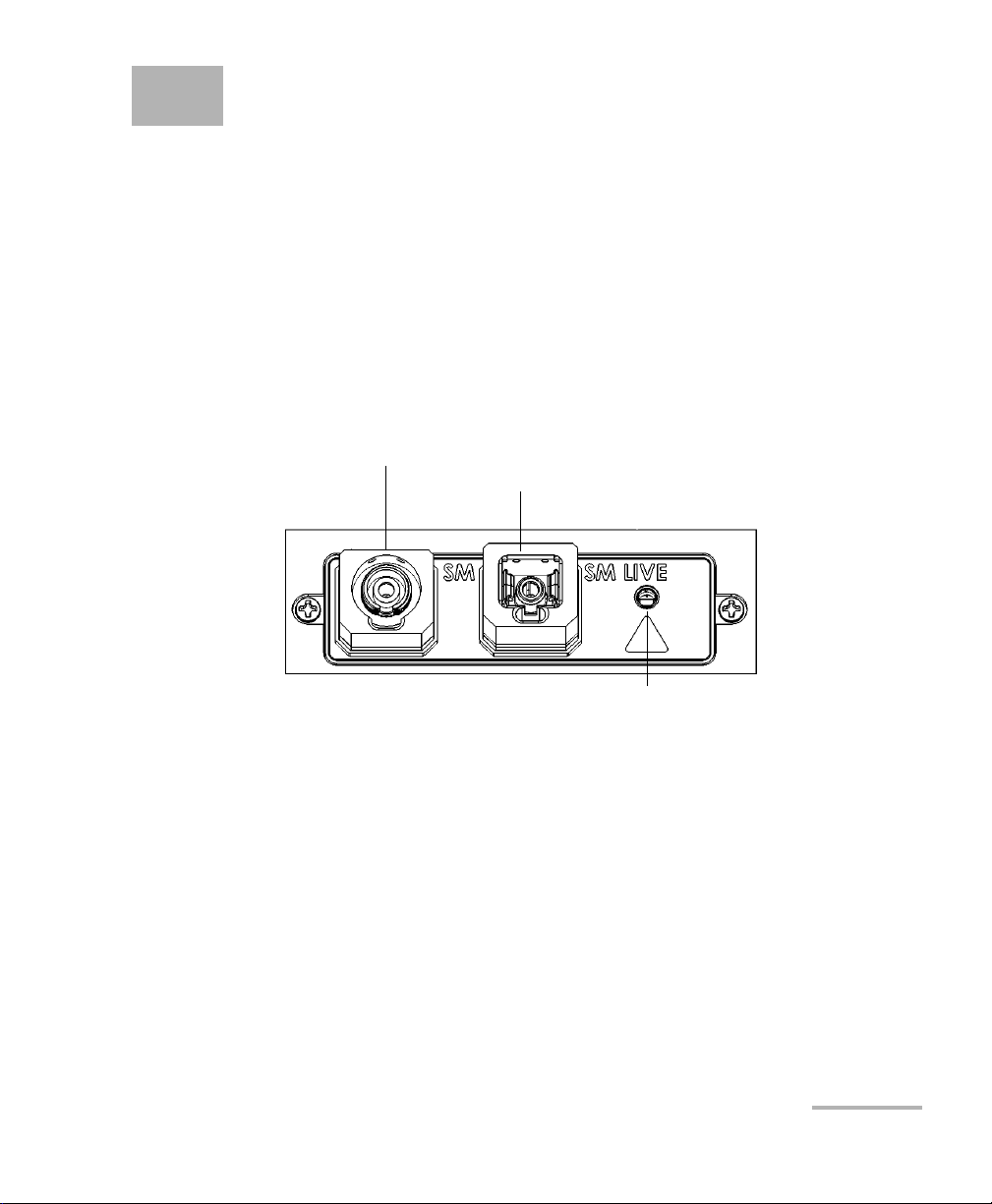
1 Introducing the OTDR
OTDR port (singlemode live)
OTDR port (singlemode)
Active LED
(on when laser is emitting)
MAX-700 Series
The OTDR allows you to characterize a fiber-optic span, usually optical
fiber sections joined by splices and connectors. The optical time domain
reflectometer (OTDR) provides an inside view of the fiber, and can
calculate fiber length, attenuation, breaks, total return loss as well as
splice, connector and total losses.
Note: In this documentation, the words “tap” and “double-tap” (related to the
use of a touchscreen) replace the words “click” and “double-click”.
OTDR 1
Page 10
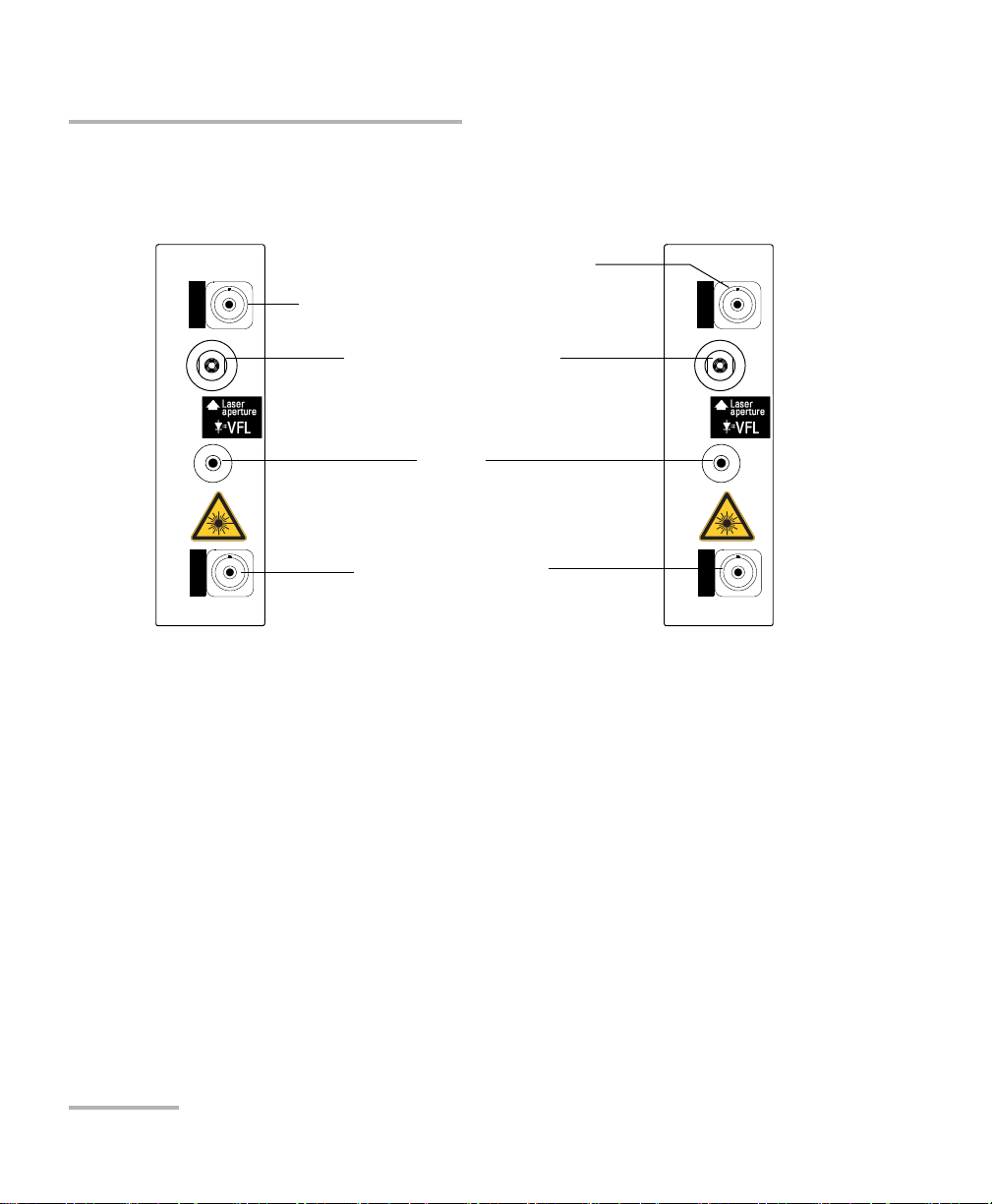
Introducing the OTDR
SM / MM OTDR
FTB-7200D
SM
MM
LIVE
Handle
Visual fault locator (VFL) port
(optional)
OTDR port (singlemode)
OTDR port (multimode)
Singlemode and
multimode models
Singlemode and
singlemode live
models
SM OTDR
FTB-7300E
SM
SM
OTDR port (for live-fiber testing)
FTB-7000 Series for FTB-2 and FTB-2 Pro
2 OTDR
Page 11
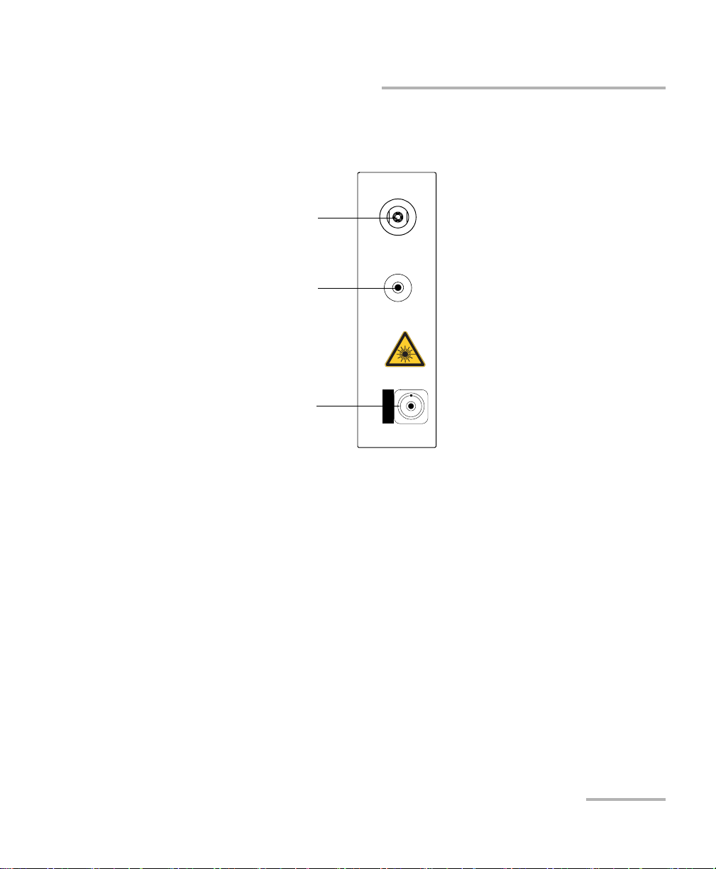
Introducing the OTDR
OTDR
OTDR port
(singlemode or multimode)
Other models
Handle
Visual fault locator
(VFL) port (optional)
FTB-7000 Series for FTB-2 and FTB-2 Pro
OTDR 3
Page 12
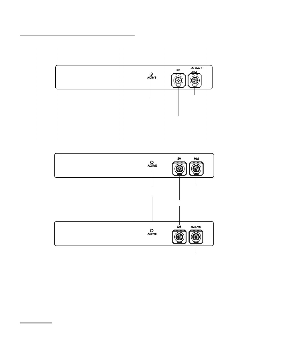
Introducing the OTDR
OTDR port (singlemode)
OTDR port (singlemode
live and On-line power
meter)
Active LED
FTB-720 / FTB-720G / FTB-720G+
FTB-730 / FTB-730G / FTB-730G+
OTDR port (singlemode)
OTDR port (multimode)
Active LED
OTDR port
(singlemode live)
4 OTDR
Page 13

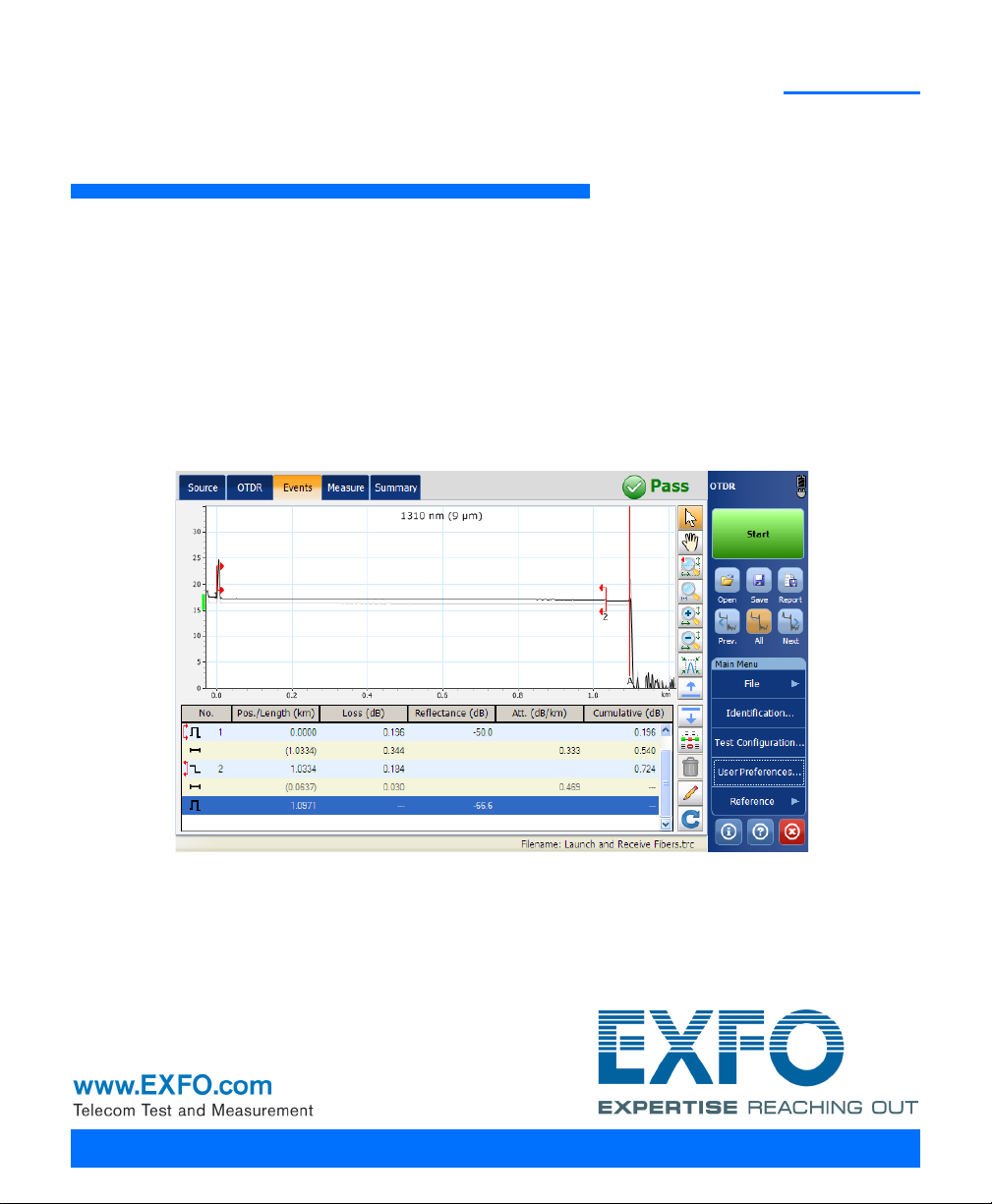
Main Window
Event
table
Button bar
Data
display
Graph
overview
window
Introducing the OTDR
Main Window
Note: Due to screen resolution, the appearance of your OTDR application may
vary slightly from the illustrations presented in this user guide.
OTDR 5
Page 14

Introducing the OTDR
Software Options
Software Options
Software options may be offered with your unit.
With the Source (SRC) software option, you can use your OTDR as a
source.
With the Real-Time (RT) software option, when working with the iOLM
application, you can also have access to the OTDR by pressing the
Launch OTDR button. In this case, the only button available to start an
acquisition is the Start Real Time button. Most of the standard OTDR
features, such as the Events tab, the Summary tab, the Identification,
and the Test Configuration button, are disabled.
The following table presents the software options available for your unit.
Software Options MAX-700B FTB-2 and FTB-2 Pro
Source (SRC) Available for purchase Already included
Real-Time (RT) Available for purchase Available for purchase
Data Post-Processing
To view and analyze traces without the OTDR application, use a computer
onto which FastReporter is already installed.
6 OTDR
Page 15

Introducing the OTDR
Distance
c
n
-- -
t
2
-- -
=
OTDR Basic Principles
OTDR Basic Principles
An OTDR sends short pulses of light into a fiber. Light scattering occurs in
the fiber due to discontinuities such as connectors, splices, bends, and
faults. The OTDR then detects and analyzes the backscattered signals. The
signal strength is measured for specific intervals of time and is used to
characterize events.
The OTDR calculates distances as follows:
where
c = speed of light in a vacuum (2.998 x 10
t = time delay from the launch of the pulse to the reception of the
pulse
n = index of refraction of the fiber under test (as specified by the
manufacturer)
8
m/s)
OTDR 7
Page 16
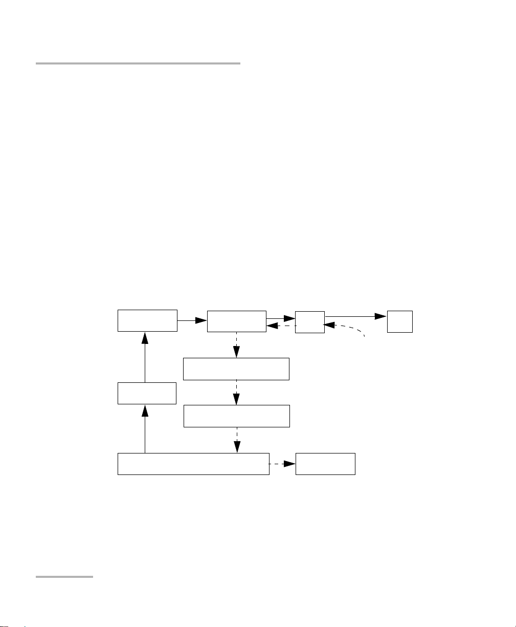
Introducing the OTDR
Microprocessor
Pulse
generator
Avalanche
photodetector (APD)
Display
Reflections come back
to the OTDR
Set of
instructions
Light pulses
Light pulses
Analog-to-digital
converter (A/D)
Returned signal
Analyzed signal
Laser
diode
Optical
coupler
OTDR
port
Fiber
OTDR Basic Principles
An OTDR uses the effects of Rayleigh scattering and Fresnel reflection to
measure the fiber’s condition, but the Fresnel reflection is tens of
thousands of times greater in power level than the backscatter.
Rayleigh scattering occurs when a pulse travels down the fiber and
small variations in the material, such as variations and discontinuities
in the index of refraction, cause light to be scattered in all directions.
However, the phenomenon of small amounts of light being reflected
directly back toward the transmitter is called backscattering.
Fresnel reflections occur when the light traveling down the fiber
encounters abrupt changes in material density that may occur at
connections or breaks where an air gap exists. A very large quantity of
light is reflected, as compared with the Rayleigh scattering. The
strength of the reflection depends on the degree of change in the index
of refraction.
When the full trace is displayed, each point represents an average of many
sampling points. You will have to zoom to see each point.
8 OTDR
Page 17
Introducing the OTDR
Conventions
Before using the product described in this guide, you should understand
the following conventions:
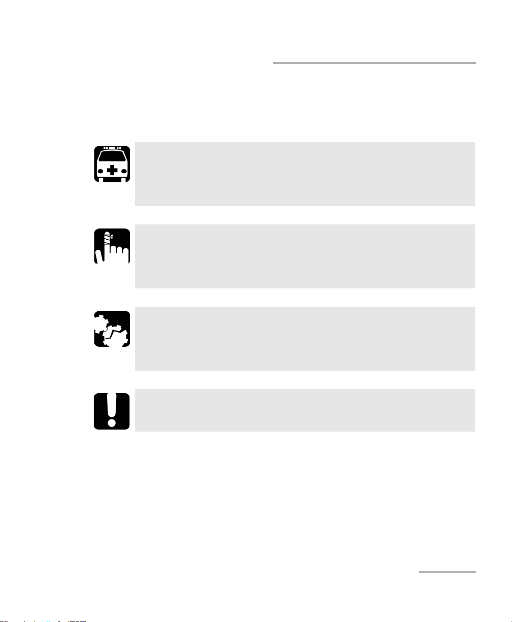
WARNING
Indicates a potentially hazardous situation which, if not avoided,
could result in death or serious injury. Do not proceed unless you
understand and meet the required conditions.
CAUTION
Indicates a potentially hazardous situation which, if not avoided,
may result in minor or moderate injury. Do not proceed unless you
understand and meet the required conditions.
CAUTION
Indicates a potentially hazardous situation which, if not avoided,
may result in component damage. Do not proceed unless you
understand and meet the required conditions.
Conventions
IMPORTANT
Refers to information about this product you should not overlook.
OTDR 9
Page 18

Page 19
2 Safety Information
General Safety Information
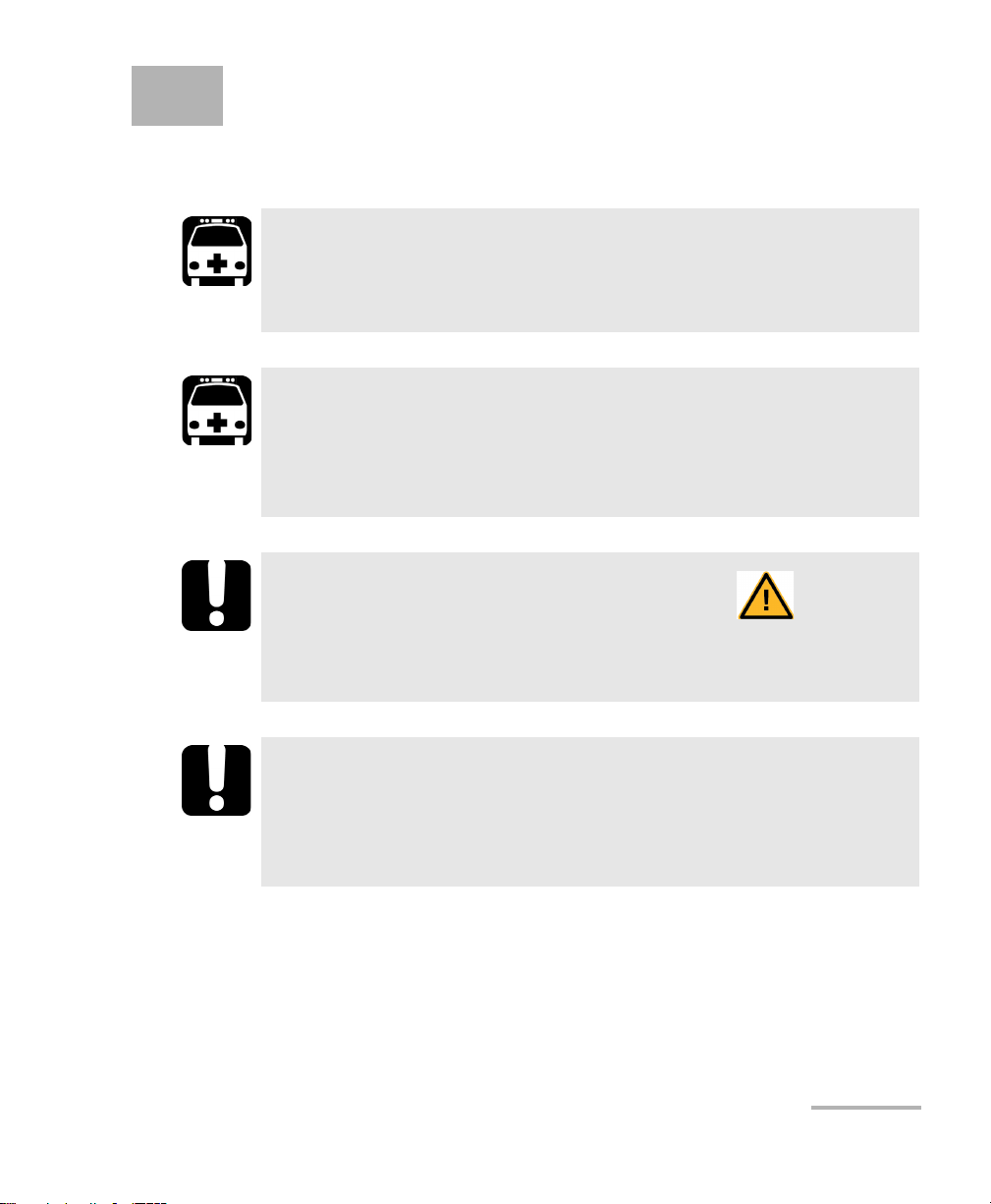
WARNING
Do not install or terminate fibers while a light source is active.
Never look directly into a live fiber and ensure that your eyes are
protected at all times.
WARNING
The use of controls, adjustments and procedures, namely for
operation and maintenance, other than those specified herein may
result in hazardous radiation exposure or impair the protection
provided by this unit.
IMPORTANT
When you see the following symbol on your unit , make sure
that you refer to the instructions provided in your user
documentation. Ensure that you understand and meet the required
conditions before using your product.
IMPORTANT
Other safety instructions relevant for your product are located
throughout this documentation, depending on the action to
perform. Make sure to read them carefully when they apply to your
situation.
OTDR 11
Page 20
Safety Information
Affixed to module’s
side panel
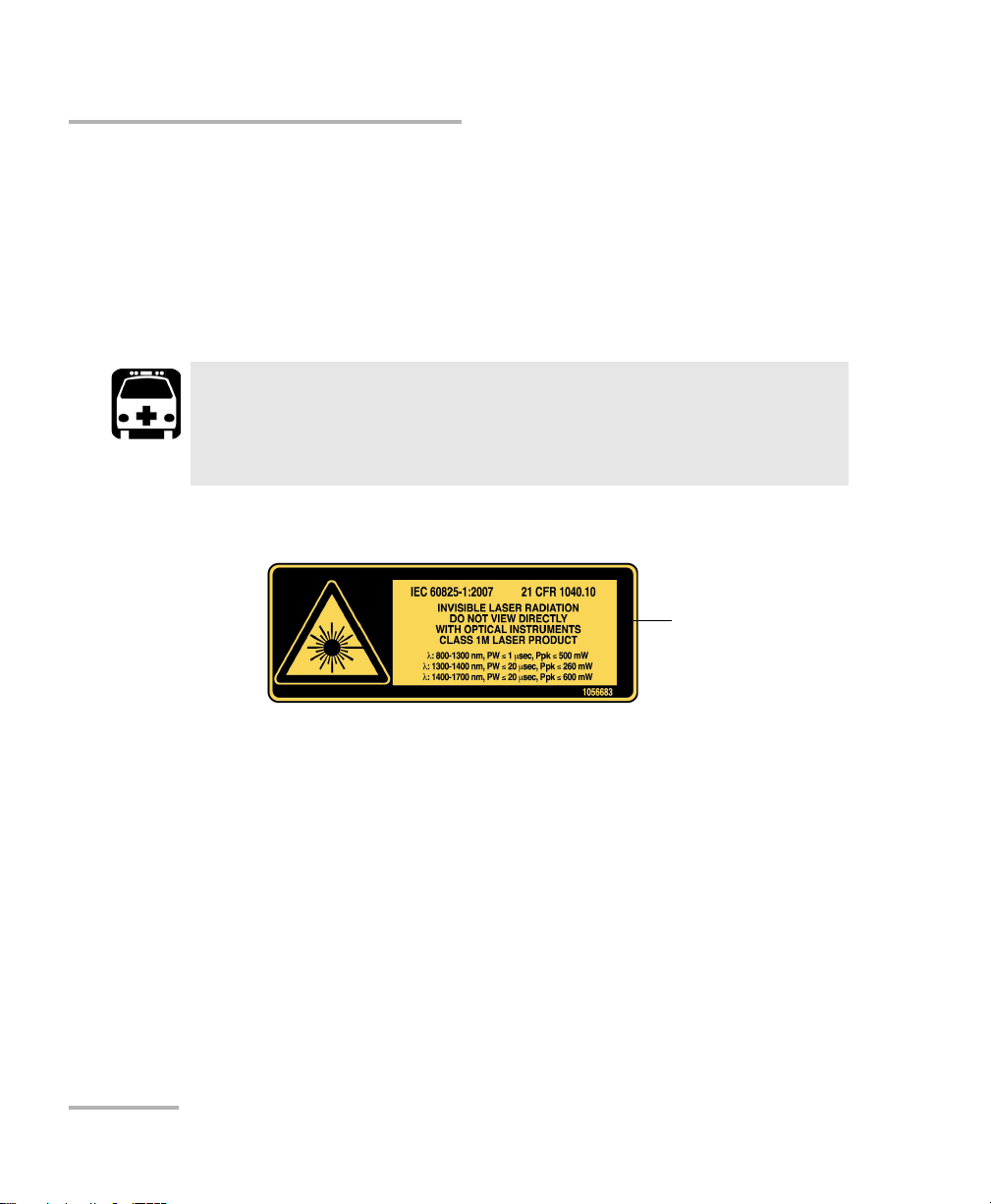
Laser Safety Information for FTB-7000 Series (Models without VFL)
Laser Safety Information for FTB-7000 Series
(Models without VFL)
Your instrument is a Class 1M laser product in compliance with standards
IEC 60825-1: 2007 and 21 CFR 1040.10, except for deviations pursuant to
Laser Notice No. 50, dated June 24, 2007. Invisible laser radiation may be
encountered at the output port.
WARNING
Viewing the laser output with certain optical instruments (for
example, eye loupes, magnifiers, and microscopes) within a
distance of 100 mm may pose an eye hazard.
The following label(s) indicate that the product contains a Class 1M source:
12 OTDR
Page 21
Safety Information
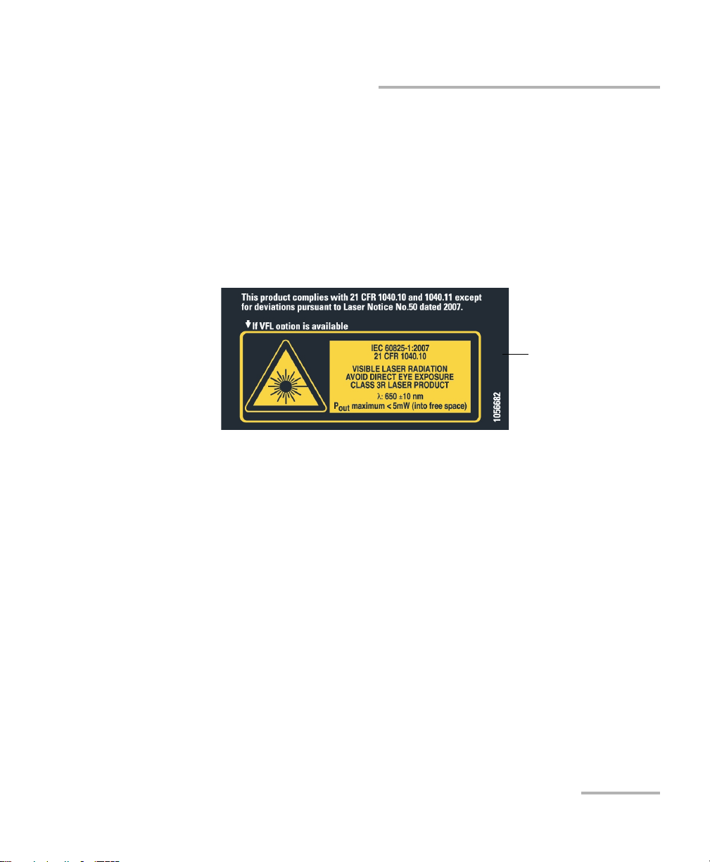
Affixed to module’s
side panel
Laser Safety Information for FTB-7000 Series (Models with VFL)
Laser Safety Information for FTB-7000 Series
(Models with VFL)
Your instrument is a Class 3R laser product in compliance with standards
IEC 60825-1: 2007 and 21 CFR 1040.10, except for deviations pursuant to
Laser Notice No. 50, dated June 24, 2007. Laser radiation is emitted at the
output port. It is potentially harmful in direct intrabeam viewing.
The following label(s) indicate that the product contains a Class 3R source:
OTDR 13
Page 22
Safety Information
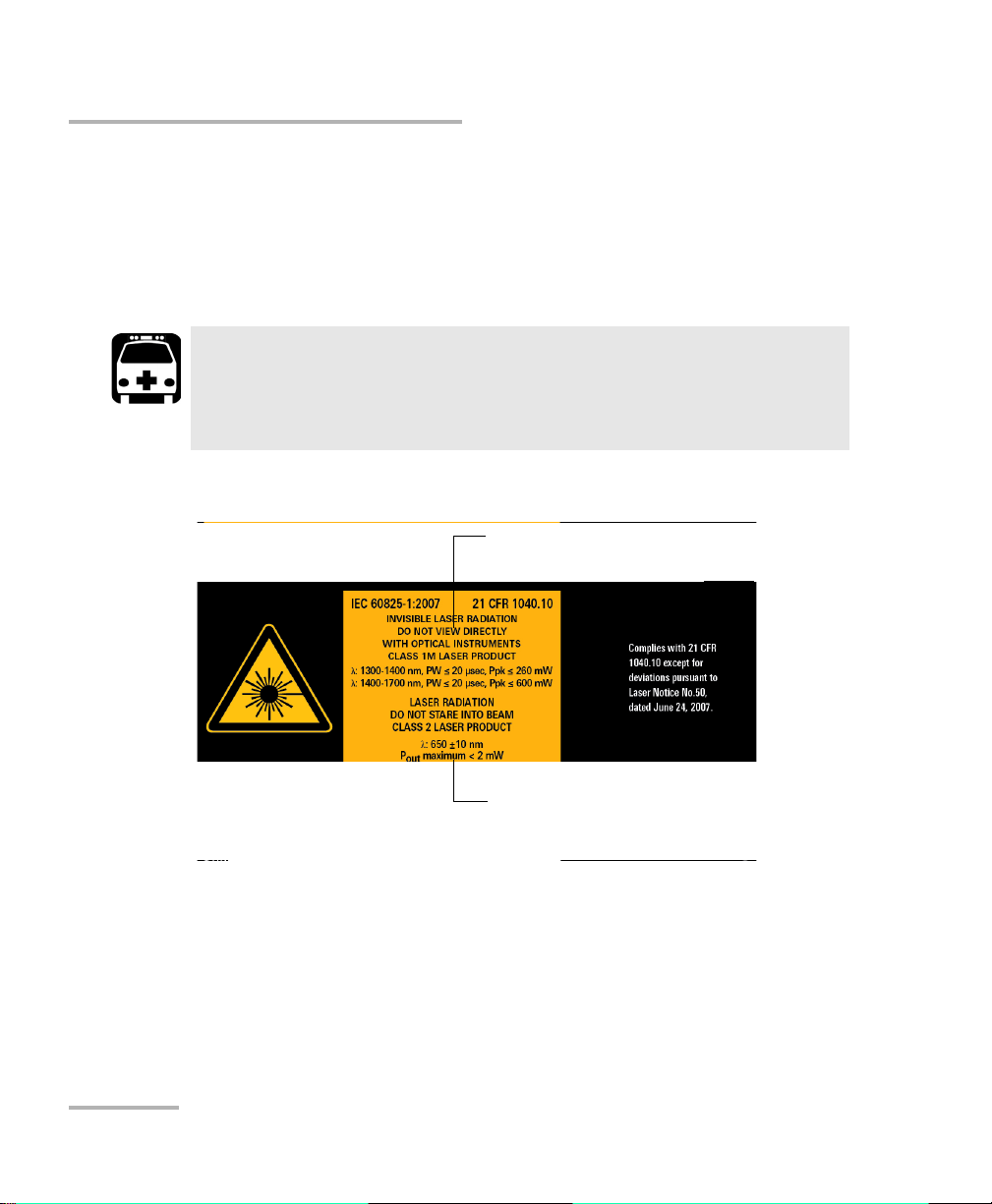
Laser information of the VFL. Always refer to
the user guide of the MaxTester Series for
the exact information.
Laser information of the test instrument
Laser Safety Information for MAX-700 Series
Laser Safety Information for MAX-700 Series
Your instrument is a Class 1M laser product in compliance with standards
IEC 60825-1: 2007 and 21 CFR 1040.10, except for deviations pursuant to
Laser Notice No. 50, dated June 24, 2007. Invisible laser radiation may be
encountered at the output port.
Viewing the laser output with certain optical instruments (for
example, eye loupes, magnifiers, and microscopes) within a
distance of 100 mm may pose an eye hazard.
The following label(s) indicate that the product contains a Class 1M source:
WARNING
Note: The label is affixed to the back panel of the unit.
For more information on product safety and equipment ratings, refer to the
user documentation of your platform.
All OTDR modules power consumption is below 10 W.
14 OTDR
Page 23
3 Preparing Your OTDR for a Test
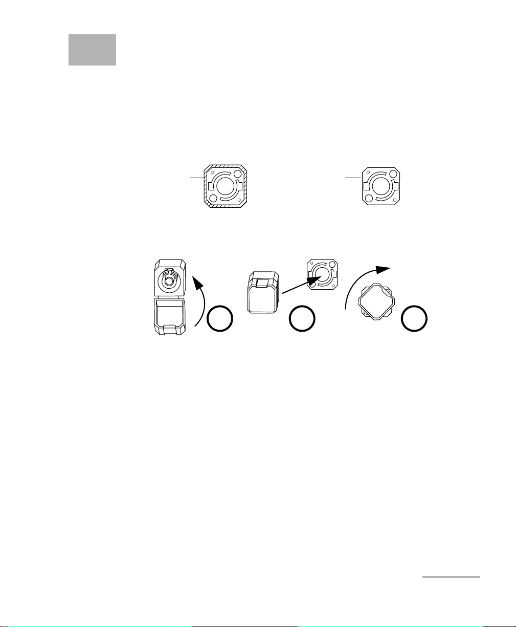
Bare metal
(or blue border)
indicates UPC
option
Green border
indicates APC
option
2 3 4
Installing the EXFO Universal Interface (EUI)
The EUI fixed baseplate is available for connectors with angled (APC) or
non-angled (UPC) polishing. A green border around the baseplate
indicates that it is for APC-type connectors.
To install an EUI connector adapter onto the EUI baseplate:
1. Hold the EUI connector adapter so the dust cap opens downwards.
2. Close the dust cap in order to hold the connector adapter more firmly.
3. Insert the connector adapter into the baseplate.
4. While pushing firmly, turn the connector adapter clockwise on the
baseplate to lock it in place.
OTDR 15
Page 24

Preparing Your OTDR for a Test
Cleaning and Connecting Optical Fibers
Cleaning and Connecting Optical Fibers
To ensure maximum power and to avoid erroneous readings:
Always inspect fiber ends and make sure that they are clean as
explained below before inserting them into the port. EXFO is
not responsible for damage or errors caused by bad fiber
cleaning or handling.
Ensure that your patchcord has appropriate connectors. Joining
mismatched connectors will damage the ferrules.
To connect the fiber-optic cable to the port:
1. Inspect the fiber using a fiber inspection microscope. If the fiber is
clean, proceed to connecting it to the port. If the fiber is dirty, clean it as
explained below.
2. Clean the fiber ends as follows:
IMPORTANT
2a. Gently wipe the fiber end with a lint-free swab dipped in isopropyl
alcohol.
2b. Use compressed air to dry completely.
2c. Visually inspect the fiber end to ensure its cleanliness.
16 OTDR
Page 25

Preparing Your OTDR for a Test
Cleaning and Connecting Optical Fibers
3. Carefully align the connector and port to prevent the fiber end from
touching the outside of the port or rubbing against other surfaces.
If your connector features a key, ensure that it is fully fitted into the
port’s corresponding notch.
4. Push the connector in so that the fiber-optic cable is firmly in place,
thus ensuring adequate contact.
If your connector features a screwsleeve, tighten the connector
enough to firmly maintain the fiber in place. Do not overtighten, as this
will damage the fiber and the port.
Note: If your fiber-optic cable is not properly aligned and/or connected, you will
notice heavy loss and reflection.
EXFO uses good quality connectors in compliance with EIA-455-21A
standards.
To keep connectors clean and in good condition, EXFO strongly
recommends inspecting them with a fiber inspection probe before
connecting them. Failure to do so will result in permanent damage to the
connectors and degradation in measurements.
OTDR 17
Page 26

Preparing Your OTDR for a Test
Naming Trace Files Automatically
Naming Trace Files Automatically
Each time you start an acquisition, the application suggests a file name
based on autonaming settings. This file name appears at the bottom of the
window.
The file name is made of one or more static parts (alphanumeric) and one
or more variable parts (numeric) that will be incremented or
decremented, according to your selection, as follows:
If you choose incrementation... If you choose decrementation...
Variable part increases until it
reaches the highest possible value
with the selected number of digits,
then restarts at 1.
Note: To decrement values, the start number must be higher than the stop
number.
After saving a result, the unit prepares the next file name by incrementing
(or decrementing) the suffix.
Variable part decreases until it
reaches 1, then restarts at the highest
possible value with the selected
number of digits.
18 OTDR
Page 27

Preparing Your OTDR for a Test
Naming Trace Files Automatically
You can select the number of digits displayed for the incremented or
decremented values.
Select "#" if you want to keep the value exactly in the same format as
defined in the start and stop values. If a value is to be incremented from 1
to 10, it becomes 1, 2, 3, ... 9, 10. One "#" is the default format.
Select two, three, or four "#" if you want all values to be expressed with the
same number of digits. The application fills the empty spaces with zeros
before the increment or decrement to ensure the appropriate format is
displayed. For example, if you select two "#" and the value is to be
incremented from 1 to 10, it becomes 01, 02, 03, ... 09, 10.
Note: If you choose not to save a particular trace file, the suggested file name
remains available for the next trace you acquire.
This function is particularly useful when testing multiple-fiber cables.
If you deactivate the automatic file naming function, the application will
use the default file name, which is Unnamed.trc.
By default, traces are saved in native (.trc) format, but you can configure
your unit to save them in Bellcore (.sor) format (see Selecting the Default
File Format on page 79).
Note: If you select the Bellcore (.sor) format, the unit creates one file per
wavelength (for example, TRACE001_1310.sor and TRACE001_1550.sor, if
you included both 1310 nm and 1550 nm in your test). The native (.trc)
format contains all wavelengths in a single file.
The autonaming parameters can be set only for files that have not been
saved yet. You will only see the parameters for the current and next
acquisition (when the test is done but not saved yet), or for the next
acquisition only (test is not done yet). Otherwise, the parameters will not
be displayed.
It is also possible to revert the settings to their default values.
OTDR 19
Page 28
Preparing Your OTDR for a Test
Naming Trace Files Automatically
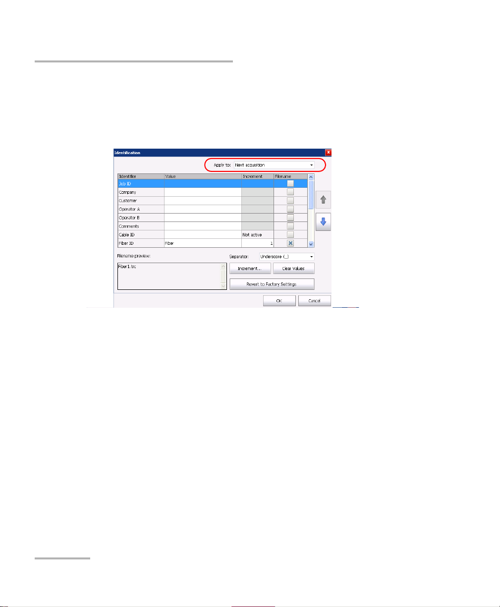
To configure the automatic file naming:
1. From the Main Menu, tap Identification.
2. From the Apply to list, ensure that Next Acquisition or Current and
Next Acquisition is selected.
3. Enter all the information as follows:
3a. Locate the row corresponding to the identifier that you want to
modify.
3b. Tap t he Value column corresponding to the desired identifier.
3c. Enter the information.
Note: You cannot edit the information in the dark gray boxes.
20 OTDR
Page 29
Preparing Your OTDR for a Test
Naming Trace Files Automatically
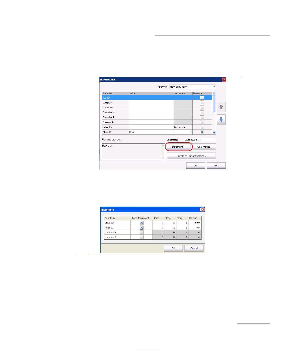
4. If you want to increment automatically the cable ID, the fiber ID or the
location (A and/or B), proceeds as follows:
4a. Tap the Increment button.
4b. In the Increment window, select the Auto Increment check box
corresponding to the identifier you want to increment.
4c. Enter the start, stop and increment values as desired.
Note: To decrement values, the start number must be higher than the stop
number.
4d. Choose the type of format in the list.
4e. Tap OK to return to the Identification window.
OTDR 21
Page 30
Preparing Your OTDR for a Test
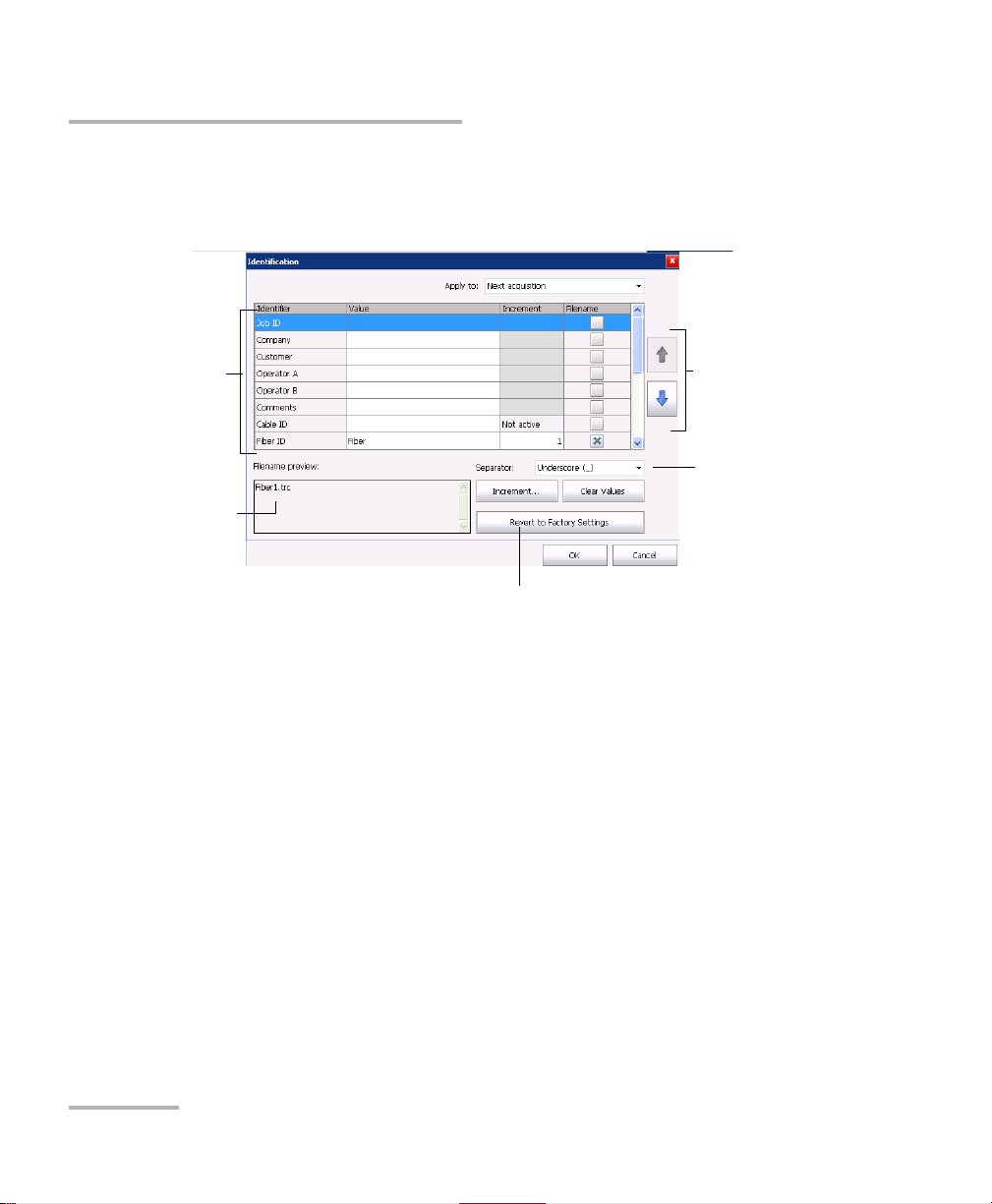
Items that can be
included in the file
name
To modify the order
of appearance of
the selected
identifiers in the
file name
This preview is
updated
automatically as you
make your selections
To s e l e ct t h e
separator in the
automatic
numbering section
To revert to factory settings (not
available for the Current acquisition)
Naming Trace Files Automatically
5. Select the desired identifiers to include in the file name. You can
change the order of appearance of the highlighted component with the
up and down arrow buttons.
6. Ta p OK to confirm your new settings and to return to the main window.
22 OTDR
Page 31

Preparing Your OTDR for a Test
Naming Trace Files Automatically
To clear the values:
1. From the Main Menu, tap Identification.
2. In the Apply to list, select Next acquisition.
3. Ta p the Clear Values button.
4. Ta p OK to return to the main window.
All values in the Value column are erased from the white boxes.
OTDR 23
Page 32

Preparing Your OTDR for a Test
Setting the IOR, RBS Coefficient, and Helix Factor
Setting the IOR, RBS Coefficient, and Helix
Factor
You s hou ld s e t th e IO R (gr oup i nd e x ), backscatter coefficient and helix
factor before performing tests in order to apply them to all newly acquired
traces. However, you can also set them at a later time but in that case, you
have to reanalyze the trace if you change the backscatter coefficient (see
Viewing and Modifying Current Measurement Settings on page 119).
The index of refraction (IOR) value (also known as group index) is
used to convert time-of-flight to distance. Having the proper IOR is
crucial for all OTDR measurements associated with distance (event
position, attenuation, section length, total length, etc.). IOR is provided
by the cable or fiber manufacturer.
The test application determines a default value for each wavelength.
You can set the IOR value for each available wavelength. You should
verify this information before each test.
The Rayleigh backscatter (RBS) coefficient represents the amount of
backscatter in a particular fiber. The RBS coefficient is used in the
calculation of event loss and reflectance, and it can usually be
obtained from the cable manufacturer.
The test application determines a default value for each wavelength.
You can set the RBS coefficient for each available wavelength.
The helix factor represents the ratio between the length of the cable
and the length of the fiber inside the cable. Since fibers within a cable
are spiraling around the cable core, the fiber length is different from
the cable length.
By setting the helix factor, the length of the OTDR distance axis is
always equivalent to the physical length of the cable.
The helix factor is expressed as a percentage. For example, a helix
factor of 1 % implies that the fiber is 1 % longer than the cable. If you
specify a helix factor of 1 %, the displayed length would be reduced by
1 % according to the cable length.
24 OTDR
Page 33

Preparing Your OTDR for a Test
Setting the IOR, RBS Coefficient, and Helix Factor
Thresholds values are saved with the measurement. It is possible to view
these thresholds values even if you open the file on another unit.
You can revert the IOR, RBS Coefficient, and Helix factor to their default
values.
To set the IOR, RBS, and helix factor parameters:
1. From the Main Menu, tap Test Configuration.
2. From the Apply to list, select Next acquisition.
IMPORTANT
In the Apply to list, Next acquisition and Current file will be
displayed if an acquisition was made but was saved. The current
trace settings, as well as the future acquisitions, will be modified.
3. From the Test Configuration window, go to the Link Definition tab.
OTDR 25
Page 34

Preparing Your OTDR for a Test
Wavelength for which
RBS and IOR will be
defined
The Revert to Factory Settings
button resets all the values in
the Link Definition tab
Setting the IOR, RBS Coefficient, and Helix Factor
4. From the Wavelength list, select the desired wavelength.
IMPORTANT
Change the default RBS coefficient only if you have values provided
by the fiber manufacturer. If you set this parameter incorrectly, your
reflectance measurements will be inaccurate.
Note: The helix factor value takes into account the difference between the length
of the cable and the length of the fiber inside the cable; it does not vary with
wavelengths. For this reason, you cannot define a different helix factor for
each wavelength.
26 OTDR
Page 35

Preparing Your OTDR for a Test
Setting the IOR, RBS Coefficient, and Helix Factor
5. If you want to apply the test configuration information to the current
acquisition, proceed as follows:
5a. Tap the Copy to Current Acquisition button.
5b. When the application prompts you, select Yes .
Note: The information in the Link Definition and Pass/Fail Thresholds tabs will
be copied to the current acquisition.
6. Ta p OK to return to the main window.
OTDR 27
Page 36

Preparing Your OTDR for a Test
Excluding and Including Span Start and Span End
Excluding and Including Span Start and Span
End
When applicable, the application includes the losses caused by the span
start and span end events to the span loss value. The application also
includes the ORL caused by the span start and span end events to the span
ORL.
When the spans are included, the loss and reflectance values associated
with the events are taken into account to determine the pass/fail
thresholds.
To exclude or include span starts and span ends:
1. From the Main Menu, select the Test Configuration button.
2. Select the Link Definition tab.
3. Under Calculation and Pass/Fail thresholds, select the inclusion of
the span start and span end you want to display in the table.
OR
To exclude the span start and span end, clear the boxes.
28 OTDR
Page 37

Preparing Your OTDR for a Test
Excluding and Including Span Start and Span End
4. If you want to apply the test configuration information to the current
acquisition, proceed as follows:
4a. Tap the Copy to Current Acquisition button.
4b. When the application prompts you, select Yes .
Note: The information in the Link Definition and Pass/Fail Thresholds tabs will
be copied to the current acquisition.
5. Ta p OK to return to the main window.
OTDR 29
Page 38

Preparing Your OTDR for a Test
Setting the Analysis Detection Thresholds
Setting the Analysis Detection Thresholds
To optimize event detection, you can set the following analysis detection
thresholds:
Splice loss threshold: To display or hide small non-reflective events.
Reflectance threshold: To hide false reflective events generated by
noise, transform non-harmful reflective events into loss events, or
detect reflective events that could be harmful to network and other
fiber-optic equipment.
End-of-fiber threshold: To stop the analysis as soon as an important
event loss occurs; for example, an event that could compromise signal
transmission toward the end of a network.
When the end of fiber detection threshold is modified for an existing
measurement, the span end position at the new end of fiber position
can be automatically reset by the application.
Note: Changing detection thresholds on the current trace leads to a reanalysis. All
manual changes made will be lost.
IMPORTANT
The end-of-fiber (EoF) threshold that you define will be used if you
let the application evaluate the acquisition settings.
If you set this threshold, an EoF event will be inserted at the first
event for which the loss crosses the threshold. The application then
uses this EoF event to determine the acquisition settings.
Setting the thresholds allow you either to ignore events with known lower
values, or to ensure that all events are detected—even the ones for which
very small values are measured.
30 OTDR
Page 39

Preparing Your OTDR for a Test
Event location
Threshold
at 0.05 dB
Threshold
at 0.1 dB
Threshold
at 0.15 dB
Second spliceFirst splice
Not displayed
Not
displayed
Setting the Analysis Detection Thresholds
The following examples show how different splice-loss threshold levels
can affect the number of displayed events, especially small non-reflective
events such as those caused by two splices. Three traces are shown,
corresponding to three threshold level settings.
Threshold at 0.05 dB
With the threshold set to 0.05 dB, two events are displayed at distances
corresponding to the location of the first and second splices.
Threshold at 0.1 dB
Only the first splice is displayed, as the threshold is set to 0.1 dB and
the second splice loss is lower than 0.1 dB.
Threshold at 0.15 dB
The first two splices are not displayed, as the threshold is set to 0.15 dB
and the first and second splice losses are lower than 0.15 dB.
Thresholds values are saved with the measurement. It is possible to view
these thresholds values even if you open the file on another unit.
OTDR 31
Page 40

Preparing Your OTDR for a Test
Setting the Analysis Detection Thresholds
To set the analysis detection thresholds:
1. From the Main Menu, tap Test Configuration.
2. From the Apply to list, select Next acquisition.
3. From the Test Configuration window, go to the Link Definition tab.
32 OTDR
Page 41

Preparing Your OTDR for a Test
Setting the Analysis Detection Thresholds
IMPORTANT
The Revert to Factory Settings button resets all the values in the
Link Definition tab.
4. Under Detection Thresholds, enter the desired values in the
appropriate boxes.
OR
If you want to revert all settings to their default values, tap the Revert to
Factory Settings button.
OTDR 33
Page 42

Preparing Your OTDR for a Test
Setting the Analysis Detection Thresholds
5. If you want to apply the test configuration information to the current
acquisition, proceed as follows:
5a. Tap the Copy to Current Acquisition button.
5b. When the application prompts you, select Yes .
Note: The information in the Link Definition and Pass/Fail Thresholds tabs will
be copied to the current acquisition.
6. Ta p OK to return to the main window.
The analysis detection thresholds you have just set will be applied to future
traces.
34 OTDR
Page 43

Preparing Your OTDR for a Test
Setting Macrobend Parameters
Setting Macrobend Parameters
Your unit can locate macrobends by comparing the loss value of an event
at a given wavelength (for example, 1310 nm) with the loss value at the
same location with another wavelength (for example, 1550 nm).
The unit will identify a macrobend when comparing two loss values if:
Of the two loss values, the greater loss occurred at the greater
wavelength.
AND
The difference between the two loss values exceeds the defined delta
loss value. The default delta loss value is 0.5 dB (which is suitable for
most fibers), but you can modify it.
You can also disable macrobend detection.
Note: Macrobend detection is only possible with singlemode wavelengths.
Filtered wavelengths or port with only one wavelength are not available for
macrobend detection.
For information on how the information about macrobends is available
after an acquisition, see Summary Tab on page 96.
OTDR 35
Page 44

Preparing Your OTDR for a Test
Setting Macrobend Parameters
To set macrobend parameters:
1. From the Main Menu, tap Test Configuration.
2. From the Apply to list, select Next acquisition.
3. Select the Link Definition tab.
4. To enable the macrobend detection, select the Macrobend check box.
OR
To disable it, clear the check box.
36 OTDR
Page 45

Preparing Your OTDR for a Test
Setting Macrobend Parameters
5. If necessary, set the delta value as follows:
5a. From the Wavelengths list, select the pair of wavelengths for
which you want to define the delta value.
Note: Only the combinations of wavelengths your module can support will be
available for a next acquisition. For a current acquisition, the available
wavelength in the file will be used.
5b. In the Delta (loss) box, enter the desired value.
5c. Repeat steps 5a and 5b for all wavelength combinations.
OTDR 37
Page 46

Preparing Your OTDR for a Test
Setting Macrobend Parameters
6. If you want to apply the test configuration information to the current
acquisition, proceed as follows:
6a. Tap the Copy to Current Acquisition button.
6b. When the application prompts you, select Yes .
7. Ta p OK to return to the main window.
38 OTDR
Page 47

Preparing Your OTDR for a Test
Setting Pass/Fail Thresholds
Setting Pass/Fail Thresholds
You can activate and set Pass/Fail threshold parameters for your tests.
Thresholds values are saved with the measurement file. It is possible to
view these thresholds values even if you open the file on another unit.
You can set thresholds for splice loss, connector loss, reflectance, fiber
section attenuation, span loss, span length, and span ORL. You can apply
the same pass/fail thresholds to all test wavelengths or set different
thresholds for each available test wavelength.
These pass/fail thresholds will be applied to the analysis results of all newly
acquired traces as well as current traces with the corresponding
wavelength.
If you work with files containing other wavelengths, the application will
automatically add these wavelengths to the list of available wavelengths.
You will then be able to define thresholds for these new wavelengths. You
can revert all thresholds to their default values.
The loss, reflectance and attenuation thresholds that you set are applied to
all events where such values can be measured.
Once the thresholds are set, the application will be able to perform
Pass/Fail tests to determine the status of the results (pass or fail).
Values that are greater than the predefined thresholds are displayed in
white on a red background in the Events table. Span length, span loss and
span ORL values are displayed in the Summary table.
OTDR 39
Page 48

Preparing Your OTDR for a Test
Value and unit
associated with
the threshold to
set
Setting Pass/Fail Thresholds
To set pass/fail thresholds:
1. From the Main Menu, select Test Configuration.
2. From the Apply to list, select Next acquisition.
3. Select the Pass/Fail Thresholds tab.
In the Apply to list, Next acquisition and Current file will be
displayed if an acquisition was made but was saved. The current
trace settings, as well as the future acquisitions, will be modified.
4. From the Wavelength list, select the wavelength for which you want to
set thresholds.
IMPORTANT
40 OTDR
Page 49

Preparing Your OTDR for a Test
The Revert to Factory
Settings button resets
all the values in the
Pass/Fail Thresholds
tab
Setting Pass/Fail Thresholds
5. Select the boxes corresponding to the thresholds that you want to use,
and enter the desired values in the appropriate fields.
Note: If you no longer want the application to take into account a particular
threshold, simply clear the corresponding check box.
Note: Selecting or clearing a particular thresholds check box will affect all the
available wavelengths, not only the selected one.
OTDR 41
Page 50

Preparing Your OTDR for a Test
Setting Pass/Fail Thresholds
6. If you want to apply the thresholds you have just defined to one or
several other wavelengths, proceed as follows:
6a. Tap the Copy to Other Wavelengths button.
6b. Select the boxes corresponding to the wavelengths for which you
want to use the same thresholds.
Note: You can use the Select All button to quickly select all boxes at the same
time.
6c. Tap OK to confirm you selection.
42 OTDR
Page 51

Preparing Your OTDR for a Test
Setting Pass/Fail Thresholds
7. If you want to apply the test configuration information to the current
acquisition, proceed as follows:
7a. Tap the Copy to Current Acquisition button.
7b. When the application prompts you, select Yes .
Note: The information in the Link Definition and Pass/Fail Thresholds tabs will
be copied to the current acquisition.
8. Ta p OK to return to the main window.
OTDR 43
Page 52

Page 53

4Testing Fibers
Several tools are available to perform complete OTDR tests; you can also
control all test parameters.
By default, all available test wavelengths are selected.
You can either set the acquisition parameters yourself or let the application
determine the most appropriate values.
In the latter case, the application will automatically evaluate the best
settings according to the fiber link currently connected to the unit.
The pulse width will be determined using a factory-defined signal-to-noise
ratio (SNR) requirement specified where the End-of-Fiber (EoF) event has
been detected.
The EoF event detection algorithm uses the end-of-fiber threshold defined
in the Test Configuration window (for more information, see Setting the
Analysis Detection Thresholds on page 30). If you are not sure about which
value to choose, revert to the factory default value for this parameter.
Although the application sets the acquisition parameters, you can modify
these values as needed, even while the acquisition is in progress. The
OTDR simply restarts the averaging each time a modification is made.
Note: You can interrupt the acquisition at any time. The application will display
the information acquired to that point.
OTDR 45
Page 54

Testing Fibers
Event
table
Tra ce
display
After analysis, events appear in the events table. For more information,
see Analyzing Traces and Events on page 93.
You can save the measurement after analysis. If former results have not
been saved yet, the application prompts you to save them before starting a
new acquisition.
46 OTDR
Page 55

Testing Fibers
To acquire traces:
1. Clean the connectors properly (see Cleaning and Connecting Optical
Fibers on page 16).
2. Connect a fiber to the OTDR port.
If your unit is equipped with two OTDR ports, ensure that you connect
the fiber to the appropriate port (singlemode, singlemode live, or
multimode), depending on the wavelength you intend to use.
CAUTION
Never connect a live fiber to the OTDR port without a proper setup.
Any incoming optical power ranging from –65 dBm to –40 dBm will
affect the OTDR acquisition. The way the acquisition will be
affected depends on the selected pulse width.
Any incoming signal greater than 10 dBm could damage your OTDR
module permanently. For live-fiber testing, refer to the SM Live port
specifications for the characteristics of the built-in filter.
3. If you want to set your own IOR (group index), RBS coefficient or helix
factor, see Setting the IOR, RBS Coefficient, and Helix Factor on
page 24.
4. If you want to set the first connector check, see Enabling or Disabling
the First Connector Check on page 57.
OTDR 47
Page 56

Testing Fibers
5. Go to the OTDR tab.
6. If you want to test in high resolution, simply select the feature (see
7. If your OTDR supports singlemode, singlemode live, or multimode
Enabling the High-Resolution Feature on page 62)
wavelengths, from the Port list, select the desired fiber type (for
live-fiber testing, select SM Live; for C fiber, select 50 m and for D fiber,
select 62.5 m).
8. Select the boxes corresponding to the desired test wavelengths.
48 OTDR
Page 57

Testing Fibers
9. Select the desired distance range, pulse, and time values. For more
information, see Setting Distance Range, Pulse Width, and Acquisition
Time on page 60.
Note: To configure different parameters for each wavelength, see Applying
Acquisition Settings by Wavelength on page 59.
10. Tap Start. If the first connector check feature is enabled, a message
will appear if there is a problem with the injection level (see Enabling
or Disabling the First Connector Check on page 57).
Note: The acquisition starts with the selected wavelength. The following
wavelengths are tested in increasing order (smallest to largest).
You can modify the acquisition parameters as needed while the acquisition
is in progress. The OTDR simply restarts the averaging each time a
modification is made. This applies only to the wavelength currently under
test. Changing the time parameter does not restart the acquisition.
OTDR 49
Page 58

Testing Fibers
11. Once the analysis is complete, save the trace by tapping Save in the
button bar.
The application will use a file name based on the autonaming
parameters you defined (see Naming Trace Files Automatically on
page 18). This file name appears in the status bar.
The files that have to be saved are sent in the default file folder
(see Setting the Default Storage Folder on page 78).
Note: The application will only display the Save As dialog box if you have
activated the feature to always be prompted when you save a file. From
this dialog box, you can change the location, the file name and the file
format.
Even if you modify the name of the file, next time you save a trace, the unit
will prepare the next file name by incrementing or decrementing the suffix.
11a.If necessary, change the folder to which the file will be saved by
tapping the parent folder button until you reach the desired
location.
11b.If necessary, specify a file name.
12. Tap OK to confirm.
50 OTDR
Page 59

Testing Fibers
Setting the Automatic Acquisition Parameters
Setting the Automatic Acquisition Parameters
When the auto-settings parameters are activated, the application
calculates the distance and pulse for the first wavelength, then for the
second wavelength, and so on. You can also enable a feature that will let
you select the optimized range and pulse for the distance as determined by
the application when the auto-settings parameters are used at least once.
To set the automatic acquisition parameters:
1. From the main window, go to the OTDR tab.
2. Go to the Time (s) dial and select the appropriate time for your test.
The default value is 15 seconds.
3. Ta p AUTO.
OTDR 51
Page 60

Testing Fibers
Setting the Automatic Acquisition Parameters
4. If you want to keep the auto-settings activated once an acquisition is
done, proceed as follows:
4a. Tap the button.
4b. Under Advanced Parameters, select the Remain in
Auto-Settings box.
4c. Tap OK to return to the main window.
52 OTDR
Page 61

Testing Fibers
Setting the Automatic Acquisition Parameters
5. If you want to use the optimized range feature, proceed as follows:
5a. Tap the button.
5b. Under Advanced Parameters, select the Use optimized range
box.
5c. Tap OK to return to the main window.
6. Ta p Start to launch the acquisition.
OTDR 53
Page 62

Testing Fibers
Defining Launch and Receive Fiber Settings
Defining Launch and Receive Fiber Settings
To define the fiber span start, you can set the launch fiber length. If you do
not know the fiber length, it is also possible to define the launch/receive
fiber by event number.
When you perform tests with your unit, you connect a launch fiber
between your unit and the fiber under test. If the launch and receive fiber
are not defined, the fiber will appear as if it was part of the fiber under test.
When you define the length of the launch fiber, the application sets the
fiber span start at the beginning of the fiber under test. It allows to
characterize the first connector at the beginning of the fiber. Therefore,
only events related to the defined fiber span will be taken into account. The
application will include the loss caused by the span start event in the
displayed values. The span start event will also be taken into account when
determining the status (pass/fail) of connector loss and reflectance.
The span start becomes event 1 and its distance reference becomes 0.
Events excluded from the fiber span are shaded in the event table, and do
not appear in the trace display. The cumulative loss is calculated for the
defined fiber span only.
When you perform tests with your unit, you can connect a receive fiber to
the fiber under test. It allows to characterize the last connector at the end
of the fiber. By default, the fiber span also includes the receive fiber. When
the receive length is mentioned, the application finds the event which is
characterized as the end of fiber and moves the span end according to a
value corresponding to the specified receive fiber length (except for
continuous or end of analysis events).
When the span end is positioned, an event should be near the new
position of the span end. If no event is found, the application will
automatically add an event where there should be one.
The application can also set the span end according to a number of events
instead of using a distance.
54 OTDR
Page 63

Testing Fibers
Defining Launch and Receive Fiber Settings
The application allows you to manually set the lengths or the events of both
your launch and receive fibers.
To set the launch and receive settings for the next acquisition:
1. From the main window, go to the OTDR tab, then tap the button.
2. Under Launch and Receive Fiber, select if you want to apply settings
By fiber lengths or By event.
OTDR 55
Page 64

Testing Fibers
Defining Launch and Receive Fiber Settings
3. Select the check boxes corresponding to your needs and enter the
appropriate information in the boxes.
4. Ta p OK to return to the main window.
56 OTDR
Page 65

Testing Fibers
Enabling or Disabling the First Connector Check
Enabling or Disabling the First Connector
Check
The first connector check feature is used to verify that the fibers are
properly connected to the OTDR. It verifies the injection level and displays
a message when an unusually high loss occurs at the first connection,
which could indicate that no fiber is connected to the OTDR port. By
default, this feature is disabled.
To enable or disable the first connector check:
1. From the main window, tap the OTDR tab then tap the button.
OTDR 57
Page 66

Testing Fibers
Enabling or Disabling the First Connector Check
2. Under Advanced Parameters, to enable the first connector check,
select the First connector check box.
OR
To disable it, clear the box.
3. Ta p OK to return to the main window.
58 OTDR
Page 67

Testing Fibers
Applying Acquisition Settings by Wavelength
Applying Acquisition Settings by Wavelength
By default, the modifications made to the parameters (distance, pulse, and
time) are applied to all wavelengths. However, it is possible to modify the
acquisition parameters independently for each wavelength.
To apply acquisition settings by wavelength:
1. From the main window, select the OTDR tab then tap the button.
2. Under Advanced Parameters, select the Apply settings by
wavelength box.
3. Ta p OK to return to the main window.
You can now set the distance range, the pulse width, and the
acquisition time independently for each wavelength.
OTDR 59
Page 68

Testing Fibers
Setting Distance Range, Pulse Width, and Acquisition Time
Setting Distance Range, Pulse Width, and
Acquisition Time
The distance range, pulse width and acquisition time are set with the
controls in the OTDR main window.
Distance: corresponds to the distance range of the fiber under test
according to the selected measurement units (see Selecting the
Distance Units on page 69).
Changing the distance range modifies the available settings of the
pulse width and leaves only the settings available for the specified
range.
Pulse: corresponds to the pulse width for the test. A longer pulse
allows you to probe further along the fiber, but results in less
resolution. A shorter pulse width provides higher resolution, but less
distance range. The available distance ranges and pulse widths
depend on your OTDR model.
Note: Not all pulse widths are compatible with all distance ranges.
Time: corresponds to the acquisition duration (period during which
results will be averaged). Generally, longer acquisition times generate
cleaner traces (this is especially true with long-distance traces)
because as the acquisition time increases, more of the noise is
averaged out. This averaging increases the signal-to-noise ratio (SNR)
and the OTDR’s ability to detect small events.
The time settings will also determine how the timer (displayed in the
toolbar) counts time during testing.
60 OTDR
Page 69

Testing Fibers
Parameter-setting dials
Selection
marker
Setting Distance Range, Pulse Width, and Acquisition Time
You can use the same distance range, pulse width and acquisition time
parameters for testing at all wavelengths on a multiwavelength OTDR. For
more information, see Applying Acquisition Settings by Wavelength on
page 59.
IMPORTANT
To test the high-resolution feature, you must set a minimum
acquisition time of 15 seconds.
To set the parameters:
From the OTDR tab:
Tap the dial corresponding to the parameter you wish to set (the
selection marker will move clockwise).
OR
Tap directly the value to select it. The selection marker will go to that
value immediately.
Note: If your OTDR supports singlemode, singlemode live, or multimode
wavelengths, settings would be applied to either singlemode, singlemode
live, or multimode wavelengths, depending on the selected fiber type
(same settings for 50 m and 62.5 m).
OTDR 61
Page 70

Testing Fibers
Enabling the High-Resolution Feature
Enabling the High-Resolution Feature
Note: This feature applies only to the FTB-2 and FTB-2 Pro platforms.
You can select the high-resolution feature to obtain more data points per
acquisition. This way, the data points will be closer to each other, which
will result in a greater distance resolution for the trace.
Note: When you test with the high-resolution feature, you should use a longer
averaging time to maintain a signal-to-noise ratio (SNR) that will be
equivalent to the one you would have had with the standard resolution.
IMPORTANT
To test the high-resolution feature, you must set a minimum
acquisition time of 15 seconds.
62 OTDR
Page 71

Testing Fibers
Enabling the High-Resolution Feature
To enable the high-resolution feature:
1. From the main window, select the OTDR tab then tap the button.
2. Under Advanced Parameters, select the High-resolution acquisition
box.
Note: If your OTDR supports singlemode, singlemode live, or multimode
wavelengths, the high-resolution feature will be activated either for the
singlemode, singlemode live, or multimode wavelengths, depending on the
selected fiber type.
3. Ta p OK to return to the main window.
OTDR 63
Page 72

Testing Fibers
2
1
Monitoring Fibers in Real-Time Mode
Monitoring Fibers in Real-Time Mode
The application allows you to immediately view sudden changes in the
fiber link. In this mode, the trace is refreshed instead of averaged until you
switch to average mode or stop the acquisition.
Note: You cannot reanalyze a trace in real-time mode.
Note: In real-time mode, the trace is refreshed at a slower rate when the graph
overview window is displayed.
Note: You can only use one wavelength at a time to monitor your fiber.
You can switch from real-time mode to the averaging time interval mode at
any time. You can also switch between wavelengths during an acquisition
(all wavelengths must be selected before starting the test).
To activate the real-time mode:
1. If your module supports singlemode, singlemode live, or multimode
wavelengths, specify the desired fiber type (for live-fiber testing, select
SM Live; for C fiber, select 50 m and for D fiber, select 62.5 m).
2. From the wavelength list, ensure that all the desired wavelengths are
selected.
64 OTDR
Page 73

Testing Fibers
Monitoring Fibers in Real-Time Mode
3. If you have the full OTDR application, tap RT. The RT button turns
orange to show that the real-time mode is activated.
4. If you have the full OTDR application, tap Start RT.
OR
If you only have access to the OTDR in Real Time mode, tap Start Real
Time.
Note: The timer is not displayed during real-time acquisition.
5. From the wavelength list, tap the wavelength value (not the checkbox)
corresponding to the wavelength that you want to monitor.
Note: Ensure that the wavelength is highlighted.
OTDR 65
Page 74

Testing Fibers
Monitoring Fibers in Real-Time Mode
To deactivate the real-time mode:
If you have the full OTDR application, when you want to stop
monitoring, tap Stop RT.
OR
If you only have access to the OTDR in Real Time mode, tap Stop Real
Time.
If you have the full OTDR application, you can also stop the real-time
acquisition by starting an averaged acquisition. All the wavelengths for
which boxes are selected will be tested in averaging time interval
mode (not only the highlighted one).
66 OTDR
Page 75

5 Customizing Your OTDR
Graph
overview
window
You can customize the appearance and behavior of your OTDR application.
Setting Event Table and Graph Display Parameters
You can include or exclude items from the events table to better suit your
needs. You can also change several trace display parameters:
Note: Hiding the fiber sections will not delete these items.
Fiber sections: You can display or hide fiber sections in the events table,
depending on the types of values you want to display. When the fiber
sections are hidden, the Att. column is also hidden.
the gridlines: You can display or hide the grid appearing on the graph’s
background. By default, the grid is displayed.
the graph background: You can display the graph with a black (invert
color feature) or a white background. By default, the background is
white.
the graph overview: The graph overview window shows you which
portion of the graph is being magnified.
Note: The application always generates graphs with a white background in the
reports.
OTDR 67
Page 76

Customizing Your OTDR
The Revert to Factory Settings
button resets all the values in
the General tab
Setting Event Table and Graph Display Parameters
To set the event table and graph display parameters:
1. From the Main Menu, select the User Preferences button.
2. Select the General tab.
3. Under Display, select the boxes corresponding to the item you want to
display or include in the table.
OR
To hide them, clear the boxes.
4. Ta p OK to return to the main window.
68 OTDR
Page 77

Customizing Your OTDR
Distance units
Selecting the Distance Units
Selecting the Distance Units
You can select the measurement units that will be used throughout the
application.
The default distance units are the kilometers.
Note: The attenuation of fiber sections is always presented in dBs per kilometer
even if the distance units you selected are not the kilometers. This follows
the standards of the fiber-optic industry that provides the attenuation
values in dBs per kilometer.
OTDR 69
Page 78

Customizing Your OTDR
Selecting the Distance Units
To select the distance units for your display:
1. From the button bar, tap User Preferences.
2. From the User Preferences window, select the General tab.
3. From the Distance unit list, select the item corresponding to the
desired distance units.
4. Ta p OK to return to the main window.
You return to the main window and the newly selected distance unit
appears everywhere units are used.
70 OTDR
Page 79

Customizing Your OTDR
Customizing the Acquisition Distance Range Values
Customizing the Acquisition Distance Range
Values
You can customize the values associated with the Range dial. Once the
customization is complete, you are ready to set the distance range value
for your test. For more information, see Setting Distance Range, Pulse
Width, and Acquisition Time on page 60.
Note: The value found by an auto acquisition cannot be modified.
To customize the distance range values:
1. From the main window, select the OTDR tab then tap the button.
2. Under Custom Parameters, if your OTDR supports singlemode or
multimode, specify the desired fiber type.
Note: The fiber type list is not displayed if the module has only one fiber type.
OTDR 71
Page 80

Customizing Your OTDR
Customizing the Acquisition Distance Range Values
3. From the Range list, select the value you want to modify.
4. When the value becomes highlighted, enter the new value.
5. Ta p OK to return to the main window.
Note: You can revert to factory values by pressing the Revert to Factory Settings
button.
72 OTDR
Page 81

Customizing Your OTDR
Customizing the Acquisition Time Values
Customizing the Acquisition Time Values
You can customize the values associated with the Duration (s) dial. The
acquisition time values represent the time during which the OTDR will
average acquisitions.
You can customize the acquisition time to improve the signal-to-noise ratio
(SNR) of the trace and enhance the detection of low-level events. The SNR
improves by a factor of two (or 3 dB) each time the acquisition time is
increased by a factor of four.
To customize the acquisition time values:
1. From the main window, select the OTDR tab then tap the button.
2. Under Custom Parameters, from the Duration (s) list, select the value
you want to modify.
OTDR 73
Page 82

Customizing Your OTDR
Customizing the Acquisition Time Values
3. When the value becomes highlighted, enter the new value.
4. Ta p OK to return to the main window.
Note: You can revert to factory values by pressing the Revert to Factory Settings
button.
74 OTDR
Page 83

Customizing Your OTDR
Selecting a Trace Display Mode
Selecting a Trace Display Mode
You can choose the way the application will display traces on-screen and
in reports. The available choices are:
Complete trace: to display the whole trace and full acquisition
distance.
Span: to display the trace from the span start to the span end.
To select a trace display mode:
1. From the Main Menu, select the User Preferences button.
2. Select the General tab.
3. From the Trace display mode list, select a display mode.
4. Ta p OK to return to the main window.
OTDR 75
Page 84

Customizing Your OTDR
Selecting the Default View
Selecting the Default View
You can select which view will be displayed by default once all the
acquisitions are performed (at all the selected wavelengths) and the
analysis of the last wavelength is complete. The default view will also be
used when opening a measurement file.
The table below indicates the views that can be displayed.
View Remarks
Keep current The tab selected before the acquisition is
OTDR Displays the graph and the control dials (lists
Events Default view.
started remains the same once the acquisition
is complete.
when graph is in full view) for the OTDR
acquisitions.
For more information, see Graph on page 94.
Displays the results in the Events table after an
acquisition.
Measure Displays the results in the Measure table after
an acquisition. This view allows you to take
measurement with markers manually.
Summary table This table gives, for each wavelength,
information such as: the pass/fail status of the
results, the span loss and span ORL values.
Span length is also displayed.
For more information, see Summary Tab on
page 96.
76 OTDR
Page 85

Customizing Your OTDR
Selecting the Default View
To select the default view:
1. From the Main Menu, select User Preferences, then the General tab.
2. From the Default view list, select the desired view.
3. Ta p OK to return to the main window.
The application will automatically switch to the selected view when
you perform the next acquisitions or open already existing files.
OTDR 77
Page 86

Customizing Your OTDR
Setting the Default Storage Folder
Setting the Default Storage Folder
The default storage folder is Data\My Documents\OTDR but you can
change the folder to better suit your needs. You can also work with a USB
key. If the USB key is not connected to the device upon saving, the
acquisitions are saved in the default storage folder.
Note: The Save As button allows you to save your files to a folder different than
the default storage folder. If you change the storage folder from the Save As
dialog box, it will be used the next time you use the Save As feature again.
The default storage folder will not be modified.
To set the default storage folder:
1. From the Main Menu, tap the User Preferences button, then select the
General tab.
2. Under File functionalities, tap the button next to Default save
folder.
78 OTDR
Page 87

Customizing Your OTDR
Selecting the Default File Format
3. In the Browse for Folder window, select the location where you want
to save the file.
Note: If you want to create a folder, you will have to do it manually via File
Manager available from the Home screen.
4. Ta p OK to exit the Browse for Folder window.
5. Ta p OK to return to the main window.
Selecting the Default File Format
You can define the default file format the application will use when you
save your traces.
By default, traces are saved in native (.trc) format, but you can configure
your unit to save them in Bellcore (.sor) format.
If you select the Bellcore (.sor) format, the unit will create one file per
wavelength (for example, TRACE001_1310.sor and TRACE001_1550.sor, if
you included both 1310 nm and 1550 nm in your test). The native format
contains all wavelengths in a single file.
Note: If you selected the feature to be prompted each time you save a
measurement, you can also modify the file format temporarily. Next time
you save a measurement, the default file format will be used.
Note: The Save As button allows you to save your files to a folder different from
that of the default file format. If you change the file format from the Save As
dialog box, it will be used the next time you use the Save As feature again.
The default file format will not be modified.
OTDR 79
Page 88

Customizing Your OTDR
Selecting the Default File Format
To select the default file format:
1. From the Main Menu, tap the User Preferences button, then select the
General tab.
2. From the Default file format list, select the type of file.
3. Ta p OK to return to the main window.
The next files will be saved in the new format.
80 OTDR
Page 89

Customizing Your OTDR
Enabling or Disabling Automated File Saving
Enabling or Disabling Automated File Saving
By default, each time you save a file, the application saves it without asking
for a file name or a folder.
The application will use a file name based on autonaming settings
(see Naming Trace Files Automatically on page 18).
To enable or disable automated file saving:
1. From the Main Menu, tap User Preferences, then select the General
tab.
2. If you want to confirm the file name, folder, or file type each time you
tap Save, select the Show confirmation on a first save check box.
OR
If you never want to be prompted, clear the check box.
3. Ta p OK to return to the main window.
The changes are applied automatically.
OTDR 81
Page 90

Page 91

6 Analyzing the Results
Distance between
span start and B
Distance between A
and B
Distance between
span start and A
Power at A
Power at B
Power difference
between A and B
Marker not selected
Marker selected
Average loss
between A and B
Manually
You can move markers and zoom in on or out of any event or trace
segment to measure splice loss, fiber section attenuation, reflectance, and
optical return loss. It is possible to do this once a trace has been acquired
or opened, or even when an acquisition is in progress.
Using Markers
You can use markers to view the position and relative loss or reflectance of
an event.
Markers are available from the Events tab (when you modify an event) or
the Measure tab (when you add an event) in the main window.
You can lock or unlock the distance between the four markers and move
them as a block. You can lock or unlock the distance between the A and a
marker pair, as well as the B and b marker pair and move them. You can
also lock a, A, b, B markers and move them as a group.
To move a marker directly from the graph:
1. Ensure that the button is selected in the zoom button bar.
OTDR 83
2. Select the marker directly on the trace display and drag it to the desired
position.
Page 92

Analyzing the Results Manually
Marker not selected
Marker selected
Arrow
Arrow
Using Markers
To move a marker with the arrow buttons:
1. From the Measure tab, tap the marker buttons to select the desired
markers.
2. Once the appropriate markers are selected, use the right and left arrow
buttons to move the markers along the trace.
Note: If you select more than one marker, they will move as a block.
To bring back a marker to the visible area:
1. Ensure that only the marker that corresponds to the one that you want
to retrieve is selected.
2. Use the left and right arrows to move the marker.
84 OTDR
Page 93

Analyzing the Results Manually
Getting Event Distances and Relative Powers
Getting Event Distances and Relative Powers
The OTDR test application automatically calculates the position of an event
and displays this distance in the events table.
You can retrieve the position of an event as well as the distance between
events manually. You can also display various relative power readings.
Distances and relative powers correspond to the X-axis and Y-axis,
respectively.
To get the distance to an event and the associated relative power
level automatically:
1. From the main window, select the Measure tab.
2. Tap to display all markers. Markers are automatically positioned at
the right location.
OTDR 85
Page 94

Analyzing the Results Manually
Getting Event Distances and Relative Powers
To get the distance to an event and the associated relative power
level manually:
1. From the main window, select the Measure tab.
2. Move marker A to the beginning of the event. For more information
about markers, see Using Markers on page 83.
86 OTDR
Page 95

Analyzing the Results Manually
Four-point
event loss
a
b
Getting Event Loss and Maximum Reflectance
Getting Event Loss and Maximum Reflectance
Event loss (expressed in dB) is calculated by measuring the signal level
reduction in Rayleigh backscatter (RBS) caused by this event. Event loss
can result from both reflective and non-reflective events.
The loss calculation provided is called the “four-point event loss”. The
four-point event loss calculation uses the least-square approximation (LSA)
method to determine the event loss. The four-point event loss corresponds
to the loss displayed in the events table.
For the four-point event loss: the LSA method is used to fit a straight
line to the backscatter data within the two regions defined by
markers a, A and b, B, that is over the regions to the left and to the right
of the event bordered by markers A and B, respectively.
The two fitted lines are then extrapolated toward the center of the
event and the loss event is directly read from the drop in power
between the two lines.
OTDR 87
Page 96

Analyzing the Results Manually
Getting Event Loss and Maximum Reflectance
Reflectance is the ratio of reflected light to input light.
Note: If you are testing in Real time, the reflectance value you will get is not
necessarily accurate.
To get event loss and maximum reflectance:
1. From the main window, select the Measure tab.
2. At the bottom of the window, tap Event. Markers a, A, B and b appear
on the graph.
3. Zoom in and position marker A at the end of the linear area preceding
the event to be measured. For more information, see Using Zoom
Controls on page 109 and Using Markers on page 83.
4. Position submarker a at the beginning of the linear area preceding the
event to be measured (must not include any significant events).
88 OTDR
Page 97

Analyzing the Results Manually
4
3
5
6
Event to be measured
Linear area
Linear area
Four-point event loss
from the areas delimited
by markers
a, A, B and b
Maximum
reflectance
Getting Event Loss and Maximum Reflectance
5. Po si ti o n marker B at the beginning of the linear area following the
event to be measured.
6. Position submarker b at the end of the linear area following the event
to be measured (must not include any significant events).
Note: For non-reflective events, will be displayed.
OTDR 89
Page 98

Analyzing the Results Manually
A-B LSA loss
a
b
Getting Section Loss and Attenuation
Getting Section Loss and Attenuation
The least-square approximation (LSA) method measures the attenuation
(loss over distance) between two points by fitting a straight line in the
backscatter data between markers A and B. The LSA attenuation
corresponds to the difference in power ( dB) over the distance between
two points.
The LSA method, when compared to a two-point method, gives an average
measurement and is more reliable when there is a high level of noise.
However, it should not be used if an event such as an echo appears
between the two markers.
A-B LSA loss: the loss of the event bordered by the markers A and B is
obtained by fitting a straight line to the backscatter data between these two
markers.
The event is then obtained by the reduction in power (dB) over the
distance between the two markers, as calculated from the slope of the
fitted line.
90 OTDR
Page 99

Analyzing the Results Manually
A-B Least-square
approximation
loss
A-B Least-square
approximation
attenuation
Getting Section Loss and Attenuation
Although this method works fairly well for splice loss, it is clearly not
appropriate for reflective events (definitely not a “straight-line” event). A-B
LSA loss is mainly used to rapidly compute loss over a given length of a
fiber section.
Note: A-B LSA event loss measurements should be used on fiber sections only.
Measuring events will not yield meaningful results.
To get section loss and attenuation:
1. From the main window, select the Measure tab.
2. Ta p the Section button. Markers A and B appear on the graph.
3. Place markers A and B at any two points on the trace. For more
information, see Using Markers on page 83.
4. Zoom in on the trace and fine-tune the marker positioning if necessary.
For more information, see Using Zoom Controls on page 109.
Note: There should not be any event between markers A and B when performing
a measurement.
OTDR 91
Page 100

Analyzing the Results Manually
Getting Optical Return Loss (ORL)
Getting Optical Return Loss (ORL)
The ORL calculation will provide the following information:
the ORL between markers A and B
the total ORL is calculated either between the span start and the span
end, or on the total fiber span, depending on the option you have
selected. For more information, see Excluding and Including Span Start
and Span End on page 28.
Optical return loss (ORL) refers to the total effect of multiple reflections
and scattering events within a fiber-optic system.
To get the ORL value:
1. From the main window, select the Measure tab.
2. At the bottom of the window, tap ORL. Markers A and B appear on the
graph.
3. Position markers A and B to delimit the area for which you want to
know the ORL value.
92 OTDR
 Loading...