

Page 1

OSICS Multifunction Platform
8-Channel Modular Platform
Programming Guide
www.EXFO.com
OSICS_PG_3v2.2
Page 2

Page 3

About This Manual
Subject This manual specifies the remote interfaces of the OSICS Mainframe and modules and
the corresponding remote commands.
Application Information in this document applies to the OSICS Mainframe version 3.06 and the
following versions of OSICS modules:
• OSICS ATN v. 1.07 and higher versions
• OSICS BKR v. 1.07 and higher versions
• OSICS DFB v. 2.38 and higher versions
• OSICS SLD v. 1.03 and higher versions
• OSICS SWT v. 1.07 and higher versions
• OSICS SWT-APC v. 1.13 and higher versions
• OSICS T100 v. 3.05 and higher versions
• OSICS TLS-AG v. 3.14 and higher versions
Intended Readers Users of this manual must be familiar with:
• Fiber optic technology
• The RS-232C and/or IEEE-488.1 interfaces used to operate the OSICS in remote
mode
• The use of the OSICS multifunction platform (see OSICS User Guide)
Date 17 September 2018
Manual Reference OSICS_PG_3v2.2
Typographical
Conventions
Command Syntax
Notation
Conventions
bold Identifies graphical interface objects such as menu names, labels,
italic Identifies references to other sections or other guides.
monospace Identifies portions of program codes, command lines, or messages
IMPORTANT Identifies important information to which you must pay particular
Notation Meaning
[...] The content between square brackets is optional.
<...> The content between angled brackets indicates the type of
| Indicates an alternative. Equivalent to "or".
buttons and icons.
displayed in command windows.
attention.
information that you must enter as parameter (command) or that is
received (response).
# Represents a numeric suffix, for example an OSICS slot number.
OSICS Programming Guide 3
Page 4

About This Manual
Symbols
Abbreviations
Used
Warning
Indicates a potentially hazardous situation which, if not avoided, could result
in death or serious injury. Do not proceed unless you understand and meet
the required conditions.
Caution
Indicates a potentially hazardous situation which, if not avoided, may result in
component damage. Do not proceed unless you understand and meet the
required conditions.
Abbreviation Meaning
GPIB General Purpose Interface Bus
LF line feed
CR carriage return
EOI End-Or-Identify
LSB Least Significant Bit
Copyright Copyright © 2012–2018 by EXFO. Published by EXFO. All rights reserved.
This documentation is provided as a user guide to EXFO customers and potential
customers only. The contents of this document may not be reproduced in any part or as
a whole, transcribed, stored in a retrieval system, translated into any language, or
transmitted in any form or by any means (electronic, mechanical, magnetic, optical,
chemical, photocopying, manual, or otherwise) without the prior written permission of
EXFO.
Product Warranty
and Limitation of
For detailed information about the sales terms and conditions, visit the EXFO web site at
www.exfo.com/how-to-buy/sales-terms-conditions
Warranty
Contact
Information
To obtain after-sales service or technical support for this product, contact EXFO at one of
the following numbers.
Technical Support Group
400 Godin Avenue
Quebec (Quebec) G1M 2K2
CANADA
Tel. USA and Canada: 1 866 683-0155
Fax: 1 418 683-9224
E-mail: support@exfo.com
For detailed information about technical support and for a list of other worldwide
locations, visit the EXFO web site at
www.EXFO.com/support
To accelerate the process, please have information such as the name and the serial
number (see the product identification label), as well as a description of your problem,
close at hand.
4 OSICS Programming Guide
Page 5

Table of Contents
About This Manual..................................................................................................................................... 3
Table of Contents ...................................................................................................................................... 5
1. Remotely Controlling the OSICS Multifunction Platform ...................................................................... 9
1.1 Switching Between Remote and Local Mode ...................................................................................... 9
1.2 Remotely Controlling the OSICS via IEEE 488.................................................................................... 10
1.3 Remotely Controlling the OSICS via USB-B (RS-232C Protocol)....................................................... 12
2. General System and Status Control ................................................................................................... 13
2.1 Communication Principles .................................................................................................................. 13
2.2 Standard IEEE Status Register Commands and Queries................................................................... 15
2.3 RS-232C Common Commands ........................................................................................................... 19
3. OSICS Mainframe Control ................................................................................................................. 21
3.1 Optical-Output Control......................................................................................................................... 22
3.2 Spectral Unit Selection ........................................................................................................................ 23
3.3 Output Power Control .......................................................................................................................... 24
3.4 Modulation Control .............................................................................................................................. 26
3.5 Working Configuration Control ........................................................................................................... 27
3.6 OSICS System Management Control.................................................................................................. 28
4. OSICS ATN Control ........................................................................................................................... 31
4.1 Unit Selection ....................................................................................................................................... 31
4.2 Attenuation Setting .............................................................................................................................. 33
4.3 Wavelength Setting .............................................................................................................................. 34
4.4 Offset Setting ....................................................................................................................................... 35
4.5 Module System-Version Information.................................................................................................. 36
5. OSICS BKR Control............................................................................................................................ 37
5.1 Unit Selection ....................................................................................................................................... 37
5.2 Reflectance Setting.............................................................................................................................. 39
5.3 Wavelength Setting .............................................................................................................................. 40
5.4 Offset Setting ....................................................................................................................................... 41
5.5 Module System-Version Information.................................................................................................. 42
6. OSICS DFB Control............................................................................................................................ 43
6.1 Optical-Output Control......................................................................................................................... 44
6.2 Unit Selection ....................................................................................................................................... 45
6.3 Output-Power Setting........................................................................................................................... 47
6.4 Diode-Current Setting .......................................................................................................................... 48
6.5 Optical Emission-Wavelength/Frequency Setting ............................................................................. 49
OSICS Programming Guide 5
Page 6

Table of Contents
6.6 Modulation Control .............................................................................................................................. 51
6.7 Calibration Control ............................................................................................................................... 55
6.8 Module Parameter-Monitoring with the OUT 1 Output...................................................................... 57
6.9 Module System-Version Information.................................................................................................. 58
7. OSICS SLD Control ............................................................................................................................ 59
7.1 Unit Selection ....................................................................................................................................... 59
7.2 Optical-Output Control......................................................................................................................... 61
7.3 Optical Output Settings........................................................................................................................ 62
7.4 Module System-Version Information.................................................................................................. 63
8. OSICS SWT Control........................................................................................................................... 65
8.1 Input/Output Selection ........................................................................................................................ 65
8.2 Module System-Version Information.................................................................................................. 69
9. OSICS SWT-APC Control................................................................................................................... 71
9.1 Operating-Mode Selection and Configuration.................................................................................... 72
9.2 Input/Output Channel Selection.......................................................................................................... 73
9.3 Unit Selection ....................................................................................................................................... 73
9.4 Optical-Output Control......................................................................................................................... 75
9.5 Output-Power Setting........................................................................................................................... 77
9.6 Optical Emission-Wavelength/Frequency Setting ............................................................................. 79
9.7 Coherence Control ............................................................................................................................... 80
9.8 Auto-peak Find Control........................................................................................................................ 81
9.9 Modulation Control .............................................................................................................................. 82
9.10 Module System-Version Information.................................................................................................. 84
10. OSICS T100 Control .......................................................................................................................... 85
10.1 Optical-Output Control......................................................................................................................... 86
10.2 Unit Selection ....................................................................................................................................... 87
10.3 Output-Power Setting........................................................................................................................... 89
10.4 Diode-Current Setting .......................................................................................................................... 90
10.5 Optical Emission-Wavelength/Frequency Setting ............................................................................. 91
10.6 Coherence Control ............................................................................................................................... 92
10.7 Auto-peak Find Control........................................................................................................................ 92
10.8 Modulation Control .............................................................................................................................. 94
10.9 Calibration Control............................................................................................................................... 96
10.10 Module Parameter-Monitoring with the OUT 1 Output...................................................................... 99
10.11 Module System-Version Information................................................................................................ 100
11. OSICS TLS-AG Control .................................................................................................................... 101
11.1 Optical-Output Control....................................................................................................................... 102
11.2 Unit Selection ..................................................................................................................................... 102
11.3 Operating-Mode Control .................................................................................................................... 105
11.4 Output-Power Setting......................................................................................................................... 107
6 OSICS Programming Guide
Page 7

Table of Contents
11.5 Optical Emission-Wavelength/Frequency Setting ........................................................................... 108
11.6 Module System-Version Information................................................................................................ 113
12. Error Codes ..................................................................................................................................... 115
13. Program Example and Library ......................................................................................................... 117
13.1 OSICS LabVIEW Library ..................................................................................................................... 117
13.2 OSICS LabVIEW Example .................................................................................................................. 118
Index...................................................................................................................................................... 121
OSICS Programming Guide 7
Page 8

Table of Contents
8 OSICS Programming Guide
Page 9

1. Remotely Controlling the OSICS Multifunction
You can remotely control the OSICS Mainframe through the following ports:
• IEEE-488.2 communication through the GPIB port
• RS-232C communication through the USB-B port
This section explains how to use these ports to remotely control the OSICS multifunction
platform.
1.1 Switching Between Remote and Local Mode
Procedures Entering the Remote Mode
• The OSICS multifunction platform automatically switches to remote mode if it
receives a command (via the USB or GPIB port).
When the OSICS multifunction platform enters into remote mode, the Mode area
displays Mode: REMOTE and the user interface control-panel is disabled.
Platform
The System Status screen remains active and displays the current module settings,
such as operating wavelength (or frequency) or output power.
Switching Back to Local Mode
• To go back to local mode, select LOCAL by pressing the right control button (see the
front panel description in the OSICS User Guide).
In GPIB, if the OSICS multifunction platform is set to local lockout condition, the
message LOCAL LOCKOUT is displayed. This means that the OSICS multifunction
platform is locked into GPIB remote-control operation: all OSICS front panel controls
are disabled and local operating mode can no longer be restored using the LOCAL
soft-key.
To restore the user interface control panel, send the "Go to local" instruction to the
OSICS multifunction platform from the computer or GPIB controller (refer to the
programming guide of your GPIB board to know the exact syntax for the "Go to local"
instruction).
OSICS Programming Guide 9
Page 10

Remotely Controlling the OSICS Multifunction Platform
Main 12 345678
Main Setup - GPIB Address
EXITESCAPE
▲
GPIB Address :
10
Modify the value.
ENTER
1.2 Remotely Controlling the OSICS via IEEE 488
Subject This section explains how to use the IEEE-488.2 GPIB interface to remotely operate the
OSICS multifunction platform.
The GPIB port is located on the rear panel and is labeled IEEE 488 (see OSICS User
Guide).
Capabilities The following table lists the OSICS GPIB capabilities.
Mnemonic Function
SH1 Complete source handshake
AH1 Complete acceptor handshake
T5 Complete talker
L3 Complete listener
SR1 Complete service request
RL1 Complete remote/local
PP0 No parallel poll
DC1 Complete device clear
DT0 No device trigger
C0 No controller
Table 1: GPIB Interface Capabilities
1.2.1 Setting the GPIB Address
Subject The default GPIB address of the OSICS is factory-set to 10. This section explains how to
modify it (possible values are 1 to 30).
Up to 15 devices may be connected on the same GPIB bus simultaneously. Each device
has its own GPIB address in the range of 0 to 30. To avoid address conflicts, you must
make sure that your OSICS GPIB address is different from the address of any other
device already connected to the GPIB port.
Procedure 1. Access the Main Setup menu (see OSICS User Guide).
2. Turn the rotary knob to put the cursor before the GPIB address menu and press the
knob to enter it.
The GPIB Address sub-menu appears and displays the current GPIB address.
10 OSICS Programming Guide
3. Enter the wanted address as follows:
Figure 1: Main Setup – GPIB Address
Page 11

Remotely Controlling the OSICS Multifunction Platform
a. Turn the rotary knob to put the cursor under the digit to modify and press the
knob to highlight it.
b. Turn the knob clockwise to increase the value or anticlockwise to decrease it and
press the knob to validate the selected digit.
c. Perform steps a. and b. for every digit you want to modify.
d. Turn the rotary knob clockwise to put the cursor under ENTER and press the
knob to validate the new address.
The new GPIB address is set and stored in memory. You do not need to restart the
OSICS Mainframe.
1.2.2 Connecting the OSICS to an IEEE 488 Controller
Subject The GPIB port enables you to connect the OSICS Mainframe to a computer and to control
it via remote commands.
Before Starting Make sure you have a GPIB cable to link the OSICS Mainframe to an IEEE-488.2 controller
(GPIB PCI card or GPIB-USB-HS module from National Instrument) connected to your
computer.
Procedure 1. Connect the GPIB port of the OSICS Mainframe to the IEEE-488.2 controller
connected to your computer via the GPIB cable.
2. Use the authorized remote GPIB commands detailed in the present guide to remotely
control the OSICS multifunction platform.
OSICS Programming Guide 11
Page 12

Remotely Controlling the OSICS Multifunction Platform
1.3 Remotely Controlling the OSICS via USB-B (RS-232C Protocol)
Subject The USB 2.0-B port is located on the on the rear panel and is labeled USB-B (see OSICS
User Guide).
The OSICS multifunction platform can receive RS-232C commands at the USB-B port
from a computer on which the appropriate USB driver is installed. To achieve this, you
must install the OSICS USB Driver on your computer in order to make the USB port appear
as an additional COM port available to the PC (see the following procedure).
Application software can then access the USB port in the same way as it would access a
standard COM port. Therefore, RS-232C commands can be sent to the OSICS using a
serial-communication terminal.
The OSICS USB Driver is available on the USB key provided with the OSICS, or from the
EXFO website.
This section explains how to connect your computer to the OSICS Mainframe and how to
install the OSICS USB driver.
Before Starting • Make sure your computer runs one of the following operating systems: Windows 10,
Windows 8, Windows 7.
If not, the OSICS USB driver is not supported by your computer.
• Make sure you have a USB-A to USB-B cable to link the OSICS Mainframe to your
computer.
Procedure 1. Do one of the following:
• Connect the OSICS USB key to the USB-A port of your computer.
• From the EXFO website (www.exfo.com/en/exfo-apps), download the OSICS
USB Driver (.zip file) and unzip it to a temporary folder on your computer.
2. In the USB Driver folder, double-click one of the following files, depending on you
Windows platform (if you select the wrong file, a message appears, prompting you to
select the other file):
• 32-bit system: OSICSUSBInstaller_x86.exe
• 64-bit system: OSICSUSBInstaller_x64.exe
The OSICS USB Driver installation wizard appears.
3. Follow the instructions displayed in the wizard window.
The OSICS USB Driver is now installed on your computer.
4. Connect the USB-B port of the OSICS to the USB-A port of your computer using a
USB-A to USB-B cable.
The OSICS USB-B port is recognized as a COM port by the computer.
5. Use the authorized remote RS-232C commands (detailed in the present guide) to
remotely control the OSICS multifunction platform.
Port Settings On your computer, make sure the port settings are configured with the following values:
• Baud rate (bits per second): 9600 bauds
• Data bits: 8
• Parity: none
• Stop bits: 1
• Flow control (handshaking): none
12 OSICS Programming Guide
Page 13

2. General System and Status Control
2.1 Communication Principles
2.1.1 Format of Messages
Message Endings Command Message Ending
A command message must end with one of the following:
• USB (RS-232C): CR (or ASCII code 13 character)
• GPIB: LF (or ASCII code 10 character) or EOI message
Response Message Ending
• All commands sent via RS-232C generate a response message from the OSICS
Mainframe to inform the computer whether the order was successfully performed
(OK) or that an error was produced (error messages are explained in the following
Error Handling section, p14).
A response message always ends with the end-of-message sequence composed of:
• the <CR> at the end of the message string
• a blank line
• the > sign placed on the next line followed by one white-space character, to
separate messages from one another along the vertical layout.
Example:
P=0.5 <CR>
P=? <CR>
will generate the following two response messages if operation is successful:
OK <CR>
>
P=0.5 DBM <CR>
>
• Commands sent via GPIB follow the standard status model, see section Standard
Status Model, p. 15.
Message Syntax
Rules
OSICS Programming Guide 13
Case
Commands are not case sensitive, you can type messages in upper-case or lower-case
characters.
White Space
White spaces are allowed only before or after a command string, but not within a
command mnemonic.
Multiple Commands
Compound commands are allowed and consist of a series of individual instructions
separated from one another by a semicolon ( ; ).
Page 14

General System and Status Control
The commands are processed by the OSICS Mainframe in the order received.
Command Length
A single command string can be up to 255 characters long. A longer command string
generates a command-error message and the buffer is cleared.
A new command cannot be sent until all the instructions of the command string already
in the buffer are completed. This will otherwise clear the buffer and generate a
command-error. Moreover all the previous commands will be lost.
Numeric Values
Numeric values are either integers or doubles depending on the definition of the
parameter.
• A numeric value can start with a leading 0
Example: P=01.2
• The = sign cannot be totally omitted but can be replaced by a white-space character.
Example: P 1.2
• White spaces are allowed before and after the = sign.
• Unit notation cannot be used after a numeric value.
• A comma cannot be used in a dot-decimal notation.
• White spaces are not allowed within a numerical value.
Error Handling The OSICS Mainframe performs error-checking on each command received and during
command execution. Errors fall into three categories and may generate one of the
following error messages:
• Execution Error
The command syntax is valid but the data contained in the command parameter is
out of valid range. The current parameter setting remains unchanged.
• Command Error
An unknown command is received or the command string has a syntax error in it.
• Device Dependent Error
Some condition due to instrument malfunction or overload has been detected.
2.1.2 Command Applicability
Commands are based on a simple two-level hierarchy:
• First-level commands affect the OSICS Mainframe only. To enter an OSICS
Mainframe command, simply type in the instruction string followed by the carriage
return character in RS-232C, as shown in the following example:
P=0.22 <CR>
This command sets the output power for all the modules installed in the OSICS
Mainframe to 0.22 mW (if mW is the selected power unit).
• Second-level commands are used to control the operation and setting parameters of
OSICS modules installed in the OSICS Mainframe.
14 OSICS Programming Guide
Page 15
General System and Status Control
Module commands require the CH#: specifier, where # is the slot number of the
module to which the command applies (ranging from 1 to 8), as shown in the
following example:
CH2:P=0.22 <CR>
This command sets the output power of the module installed in the channel-slot 2 to
0.22 mW (if mW is the selected power unit).
Similarly, the OSICS modules send a response statement to every command received
and executed. Response messages are similar in syntax to programming commands'
responses and feature the channel-specifier CH# in front of the message to differentiate
between channels.
2.2 Standard IEEE Status Register Commands and Queries
2.2.1 Standard Status Model
Status Model The status word is an 8-bit variable that relates to the status of the OSICS Mainframe and
error reporting as well. It contains a number of binary indicators which can be used by
the controller for an optimal synchronization between the OSICS Mainframe and the
controller. They indicate to the controller the nature of the current operation as well as
the errors encountered.
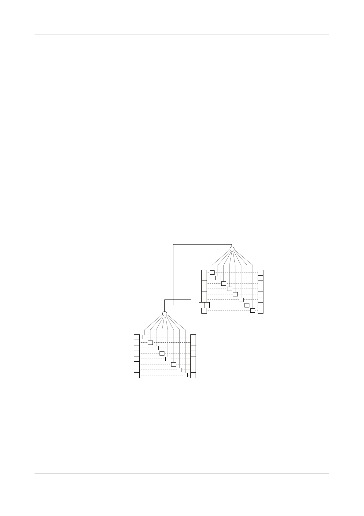
The following figure shows the standard IEEE status model.
7XEXYW&]XI
6IKMWXIV1EWO
34'
65'
5:)
(()
'1)
965
432
)<)
)ZIRX7XEXYW
6IKMWXIV)76
7XEXYW&]XI
6IKMWXIV78&
1%:
)7&
657
34'
177
)ZIRX7XEXYW
6IKMWXIV1EWO
Figure 2: Status Word Model
Two mask registers are associated with the Status Byte register (STB) and the standard
Event Status Register (ESR). These masks are used to control the service request
operation of the instrument.
In the status and standard event registers, individual bits are validated by setting to 1 the
corresponding bit in the mask register. Once the required bits have been set in each
OSICS Programming Guide 15
Page 16

General System and Status Control
mask register, the summary bit will be set to 1 when the corresponding status or event
register bits are set to 1.
The summary bit is obtained by performing a logical AND operation between each
register and the corresponding mask register, and then a logical OR operation between
all individual bits of the result.
Status Byte Register
Bit
Name Meaning
Number
7OPC
(OPeration Complete)
6RQS
(ReQuest Service)
Set to 1 once the last command has been
completed.
Set to 1 if a service request has been generated by
the OSICS Mainframe. This bit remains activated
until a serial poll has been performed.
6MSS
(Master Summary
Status)
Set to 1 together with the RQS bit. This bit remains
activated as long as the condition that has lead to a
service request is high.
It is cleared as soon as this condition ceases. This
bit can be read by the *STB? command.
5ESB
(Event Status Bit)
4MAV
(Message AVailable)
Set to 1 as soon as one or more bits in the Event
Status Register (ESR) are activated.
Set to 1 if a message is available and ready to be
read in the output queue. This bit remains activated
as long as the output queue has not been emptied.
Event Status Register
The following table gives the meaning of each bit in the Event Status register (ESR).
Bit
Name Meaning
Number
7 PON (Power ON) Set to 1 once the instrument initialization routine has
been completed.
6 URQ (User ReQuest) Set to 1 to indicate that an instrument front-panel key
has been pressed.
5 CME (ComMand Error) Set to 1 to indicate a command syntax error or an
unknown command.
4 EXE (EXecution Error) Set to 1 when a parameter value is out of the valid
range or when a command cannot be executed.
3 DDE (Device Dependent
Error)
Set to 1 if a malfunction has occurred on the
instrument or an overload condition has been
reached.
2 QYE (QuerY Error) Set to 1 in either of those two cases:
• The GPIB controller has attempted to read from
the OSICS Mainframe while the output queue
was empty.
• The data in the GPIB output queue has been
overwritten and lost.
16 OSICS Programming Guide
Page 17

General System and Status Control
Task
Synchronization
Bit
Number
1 RQC (ReQuest Control) This bit may not be set to 1, since the OSICS
0 OPC (OPeration
The Event Status Register is cleared each time it is read by the controller. When the
execution of a command line begins, the OPC bit is cleared.
The GPIB interface of the OSICS Mainframe performs tasks sequentially in the order
received; it does not support overlapping tasks.
• The OPC (OPeration Complete) bit is cleared while the instruction is being processed
• The MAV (Message AVailable) bit indicates that messages are available in the
To ensure a proper sequence of events, it may be useful to combine the use of the
STatus Byte Register (STB) with the Event Status Register (ESR). The most relevant bit in
the STB byte is bit 4 (MAV). The STB byte can be read either through a serial poll or as a
response to the *STB? query.
Name Meaning
instrument does not work as an IEEE-488.2 bus
controller.
In most cases this bit is set to 1 as soon as a
Complete)
and set to 1 once it has been completed. This is particularly useful when setting a
channel to a new wavelength, as this operation may take a few seconds to complete.
The computer should verify this flag until it is set to 1 and then only proceed to the
next instruction. The status of the OPC flag is available through serial-polling the STB
byte register. The OPC flag is contained in bit 7 of the STB byte register.
output buffer and ready to be read. For instance, if a query command was sent, the
computer must wait until the response message is placed in the output queue before
reading it. If several queries were sent via a compound command, the MAV flag
remains activated until all response messages have polled by the computer. The
MAV flag is contained in bit 4 of the STB byte register.
command has been completely executed.
Error Handling If different types of errors occur, relevant bits in the Event Status Register (ESR) are set
to 1. The following diagram shows the ESR error model:
34'
(()
)<)
'1)
The ESR byte can be read via the *ESR? query.
The relevant bits in this control byte are the following bits:
• 0 (OPeration Complete: OPC)
• 3 (Device Dependent Error: DDE)
• 4 (EXecution Error: EXE)
• 5 (CoMmand Error: CME).
)ZIRX7XEXYW
6IKMWXIV)76
We recommend reading the ESR bit each time a command is sent to help trace errors
throughout programmed operation, identify possible causes for errors and make the
necessary programming adjustments.
Caution
Reading the ESR byte with the *ESR? query command clears all the bits in the
Event Status Register. Therefore, we recommend reading all significant bits
at the time of query to ensure no relevant information is left out or lost.
OSICS Programming Guide 17
Page 18

General System and Status Control
2.2.2 Common IEEE Commands and Queries
To accelerate and secure the exchange of information between the controller and the
OSICS Mainframe, we recommend checking the values of the Status Register and of the
standard Event Status Register using the IEEE-488.2 common commands presented in
the following table.
Command Parameter Action OSICS Response
*CLS none Clears the Event Status Register and the
output queue. Sets the OPC bit to 1.
The CLS instruction is automatically sent
to each module.
*ESE Integer
value
(0 to 255)
*ESE? none The value of ESE is placed in the output
*ESR? none Standard Event Status Register query.
*IDN? none IDeNtification query.
*OPC none Waits until the pending command is
*OPC? none Waits until OPC bit is true, then places “1”
*RST none The input buffer is cleared. The command
*SRE Integer
value
(0 to 255)
The standard event mask register is set to
a value equal to the parameter of ESE
command.
If the parameter is out of the range of 0 to
255, this triggers the “Execution Error”.
queue.
The value of the standard event register is
placed into the output queue and the
standard event register is cleared.
completed, then sets the OPC bit in the
Event Status Register.
in the output queue, followed by the LF
character.
interpreter is reset and a reset instruction
is sent to every module. The status and
event registers are cleared. Sets the OPC
bit to 1.
Sets the value of the Service Request
Enable Register. SRE determines which
event triggers a serial poll. SRE is
assigned the value of its parameter. For
example, if bit 4 is set, this means that a
service request will be generated when a
message becomes available in the output
queue.
If the parameter is out of the range from 0
to 255, this triggers the “Execution Error”.
Returns the value of
ESE (0 to 255).
Returns the value of
the ESR byte
(0 to 255).
EXFO,OSICS,
<serial number>,
<software version>
/<FPGA version>
This command
always returns 1.
OK
18 OSICS Programming Guide
Page 19

General System and Status Control
Command Parameter Action OSICS Response
*SRE? none Reads the value of the SRE register. Value of the SRE
register (0 to 255).
*STB? none STatus Byte query.
The value of the status byte register is
sent to the output queue. STB contains
Value of the STB
status byte (0 to
255).
the MAV flag that takes bit number 4.
In the STB? query, bit 6 is assigned the
MSS flag rather than the RQS flag, unlike
the standard STB.
*WAI none Does nothing but wait until the pending
command has been completed.
2.3 RS-232C Common Commands
Subject This section describes the ECHON command, which is useful for viewing the characters
keyed in at the terminal.
Setting the echo mode by using the ECHON command is needed for some terminals and
terminal emulation programs that do not feature local echo, otherwise typed characters
cannot be seen.
Before Starting Make sure that the "echo" feature is enabled on the terminal emulation program you use.
Commands
Command/
Query
ECHON none Sets the OSICS Mainframe to echo each typed
Parameter Description OSICS
Mainframe
Response
OK
character received back to the terminal.
ECHOFF none Default setting.
OK
Cancels the echo mode on the OSICS Mainframe.
If the local operating mode is restored using the
front-panel LOCAL button, the echo mode is
automatically switched off and restored to
default: ECHOFF.
OSICS Programming Guide 19
Page 20

General System and Status Control
20 OSICS Programming Guide
Page 21

3. OSICS Mainframe Control
The following table gives an overview of all available commands and queries for OSICS
Mainframe control.
Command/Query Corresponding Section
Optical-Output Control
Spectral Unit Selection
Output Power Control
Modulation Control
Working Configuration Control
OSICS System Management
Control
DISABLE DISABLE, p. 22
ENABLE ENABLE, p. 22
ENABLE? ENABLE?, p. 22
GHZ GHZ, p. 23
NM NM, p. 23
NM? NM?, p. 23
DBM Power Unit Selection, p. 24
MW
MW?
P= Power Setting, p. 25
P?
MOD_SRC MOD_SRC?, p. 26
MOD_SRC? MOD_SRC?, p. 26
MOD_F= MOD_F=, p. 26
MOD_F? MOD_F?, p. 27
SAVE SAVE, p. 27
RECALL RECALL, p. 27
*IDN? *IDN?, p. 28
*RST *RST, p. 28
INTERLOCK? INTERLOCK?, p. 28
PRESENT? PRESENT?, p. 29
BKRATNMAIN DFB T100SLD SWT TLS-AGSWT APC
OSICS Programming Guide 21
Page 22

OSICS Mainframe Control
3.1 Optical-Output Control
3.1.1 DISABLE
Syntax DISABLE
ATN MAINBKRDFBT100 SLDSWTTLS-AG SWT APC
Parameter None.
Description Default setting.
Disables the laser output on all installed OSICS modules.
OSICS Response • RS-232C: OK
• GPIB: none, see section Standard Status Model, p. 15.
3.1.2 ENABLE
Syntax ENABLE
Parameter None.
Description Enables the laser output on all installed OSICS modules.
OSICS Response • RS-232C: OK
• GPIB: none, see section Standard Status Model, p. 15.
3.1.3 ENABLE?
Syntax ENABLE?
Parameter None.
Description Returns the current state of the OSICS Mainframe laser output master control.
OSICS Response • ENABLED: the laser is set to ENABLE.
• DISABLED: the laser is set to DISABLE.
22 OSICS Programming Guide
Page 23

OSICS Mainframe Control
3.2 Spectral Unit Selection
3.2.1 GHZ
Syntax GHZ
Parameter None.
Description Sets the frequency in GHz as the spectral unit on all modules throughout the system.
OSICS Response • RS-232C: OK
• GPIB: none, see section Standard Status Model, p. 15.
3.2.2 NM
Syntax NM
Parameter None.
Description Default setting.
Sets the wavelength in nm as the spectral unit on the OSICS Mainframe and all installed
OSICS modules.
OSICS Response • RS-232C: OK
• GPIB: none, see section Standard Status Model, p. 15.
3.2.3 NM?
Syntax NM?
BKRATNMAIN DFB T100SLD SWT TLS-AGSWT APC
Parameter None.
Description Returns the current spectral unit used on the OSICS Mainframe and all installed OSICS
modules.
OSICS Response • 1: the current spectral unit used is nm.
• 0: the current spectral unit used is GHz.
OSICS Programming Guide 23
Page 24

OSICS Mainframe Control
3.3 Output Power Control
3.3.1 Power Unit Selection
ATN MAINBKRDFBT100 SLDSWTTLS-AG SWT APC
3.3.1.1 DBM
Syntax DBM
Parameter None.
Description Sets dBm as the power unit on all modules. All power-related functions throughout the
OSICS Mainframe now use dBm as power unit.
OSICS Response • RS-232C: OK
• GPIB: none, see section Standard Status Model, p. 15.
3.3.1.2 MW
Syntax MW
Parameter None.
Description Default setting.
Sets mW as the power unit on all modules. All power-related functions throughout the
OSICS Mainframe now use mW as power unit.
OSICS Response • RS-232C: OK
• GPIB: none, see section Standard Status Model, p. 15.
3.3.1.3 MW?
Syntax MW?
Parameter None.
Description Returns the current power unit used on the OSICS Mainframe and all installed OSICS
modules.
OSICS Response • 1: the current power unit used is mW.
• 0: the current power unit used is dBm.
24 OSICS Programming Guide
Page 25

OSICS Mainframe Control
3.3.2 Power Setting
3.3.2.1 P=
Syntax P=xx.xx|(±)xx.xx
Parameter • [±]xx.xx: optical output power in dBm, if the unit is set to dBm (see section DBM,
p. 24). Possible values are given in the Technical Specifications section
corresponding to the installed modules in the OSICS User Guide.
• xx.xx: optical output power in mW, if the unit is set to mW (see section MW, p. 24).
Possible values are given in the Technical Specifications section corresponding to
the installed modules in the OSICS User Guide.
Description Sets the optical output power of all modules to the same value, depending on the
selected power unit (see section Power Unit Selection, p. 24).
OSICS Response • RS-232C: OK
• GPIB: none, see section Standard Status Model, p. 15.
BKRATNMAIN DFB T100SLD SWT TLS-AGSWT APC
3.3.2.2 P?
Syntax P?
Parameter None.
Description Returns the optical output power value set for the modules, according to the selected
power unit. The format of the response depends on the power unit selected (see section
Power Unit Selection, p. 24).
The returned response is the value set using the P= command (see section P=, p. 25), it
does not give the power of the installed modules.
OSICS Response • P=xx.xx: output power value in mW.
• P=±xx.xx: output power value in dBm.
OSICS Programming Guide 25
Page 26

OSICS Mainframe Control
3.4 Modulation Control
3.4.1 MOD_SRC
Syntax MOD_SRC INT|EXT
ATN MAINBKRDFBT100 SLDSWTTLS-AG SWT APC
Parameters • INT: INTERNAL digital modulation signal. The internal source uses the OSICS
Mainframe on-board modulation signal generator. To set the frequency of the OSICS
internal TTL modulation, use the MOD_F command (see section MOD_F=, p. 26)
• EXT: EXTERNAL digital modulation signal. In this case, you must connect a TTL
signal generator to the Mod. In BNC connector located at the rear panel of the OSICS
Mainframe (see OSICS User Guide).
Description Sets the type of modulation source of the OSICS Mainframe.
OSICS Response • RS-232C: OK
• GPIB: none, see section Standard Status Model, p. 15.
3.4.2 MOD_SRC?
Syntax MOD_SRC?
Parameter None.
Description Returns the type of digital (TTL) modulation source currently selected for the OSICS.
OSICS Response • MOD_SRC=INT: the modulation source is set to INTERNAL.
• MOD_SRC=EXT: the modulation source is set to EXTERNAL.
3.4.3 MOD_F=
Syntax MOD_F=xxxxxxx
Parameter • xxxxxxx: frequency in Hz, in the range 123 Hz to 1000000 Hz (1 MHz).
Default value: 200 Hz
Description Sets the frequency of the OSICS Mainframe internal digital (TTL) modulation source.
If the OSICS Mainframe is not able to generate the exact value of the frequency setting, it
applies the nearest available frequency value, right under the value of the setting.
OSICS Response • RS-232C: OK
• GPIB: none, see section Standard Status Model, p. 15.
26 OSICS Programming Guide
Page 27

OSICS Mainframe Control
3.4.4 MOD_F?
Syntax MOD_F?
Parameter None.
Description Returns the frequency of the OSICS internal digital (TTL) modulation source in Hz.
OSICS Response MOD_F=xxxxxxx
3.5 Working Configuration Control
The commands detailed in this section enable you to load or save working
configurations. For more details on working configuration, see OSICS User Guide.
3.5.1 SAVE
Syntax SAVE STARTUP|A|B|C|D
Parameters • STARTUP: configuration loaded at OSICS startup.
• A: A configuration memory.
• B: B configuration memory.
• C: C configuration memory.
• D: D configuration memory.
Description Saves the current OSICS Mainframe and module configuration settings to the selected
configuration memory.
OSICS Response • RS-232C: OK
• GPIB: none, see section Standard Status Model, p. 15.
BKRATNMAIN DFB T100SLD SWT TLS-AGSWT APC
3.5.2 RECALL
Syntax RECALL DEFAULT|STARTUP|A|B|C|D
Parameter • DEFAULT: factory-set DEFAULT configuration type.
• STARTUP: STARTUP configuration type.
• A: A configuration memory.
• B: B configuration memory.
• C: C configuration memory.
• D: D configuration memory.
OSICS Programming Guide 27
Page 28

ATN MAINBKRDFBT100 SLDSWTTLS-AG SWT APC
OSICS Mainframe Control
Description Loads the selected configuration type.
OSICS Response • RS-232C: OK
• GPIB: none, see section Standard Status Model, p. 15.
3.6 OSICS System Management Control
3.6.1 *IDN?
Syntax *IDN?
Parameter None.
Description Returns information about the OSICS Mainframe.
OSICS Response EXFO,OSICS,<serial number>,<software version>/<FPGA version>
3.6.2 *RST
Syntax *RST
Parameter None.
Description • Resets the OSICS Mainframe and all modules to the same state as after system turn-
on and initialization.
• Clears the input queue.
• Sets the OPC bit to 1.
The command interpreter is reset and a reset instruction is sent to every module.
The status and event registers are cleared.
OSICS Response • RS-232C: OK
• GPIB: none, see section Standard Status Model, p. 15.
3.6.3 INTERLOCK?
Syntax INTERLOCK?
Parameter None.
Description Returns the current state of the remote interlock mode.
OSICS Response • 1: the remote interlock is on (laser switched off).
• 0: the remote interlock is off (laser switched on).
28 OSICS Programming Guide
Page 29

OSICS Mainframe Control
3.6.4 PRESENT?
Syntax PRESENT? #
Parameter • #: slot number of the module, in the range 1 to 8.
Description Returns the type of OSICS module installed in channel-slot number #. Each type of OSICS
module has its own module code.
OSICS Response • -1: empty slot.
• 1: the module installed in the selected slot is a T100 module.
• 2: the module installed in the selected slot is a DFB or SLD module.
• 7: the module installed in the selected slot is an SWT module.
• 8: the module installed in the selected slot is an ATN or BKR module.
• 10: the module installed in the selected slot is a TLS module.
BKRATNMAIN DFB T100SLD SWT TLS-AGSWT APC
OSICS Programming Guide 29
Page 30

ATN MAINBKRDFBT100 SLDSWTTLS-AG SWT APC
OSICS Mainframe Control
30 OSICS Programming Guide
Page 31

4. OSICS ATN Control
The following table gives an overview of all available commands and queries for
OSICS ATN control.
Command/Query
Unit Selection (p. 31) CH#:GHZ
CH#:NM
CH#:NM?
Attenuation Setting (p. 33) CH#:ATN
CH#:ATN?
CH#:ATN_MIN_MAX?
Wavelength Setting (p. 34) CH#:L
CH#:L?
CH#:LREF?
Offset Setting (p. 35) CH#:OFFSET
CH#:OFFSET?
Module System-Version Information
(p. 36)
CH#:FIRM?
CH#:*IDN?
CH#:TYPE?
BKRATN DFB T100SLD SWT TLS-AGSWT APCMAIN
4.1 Unit Selection
4.1.1 CH#:GHZ
Syntax CH#:GHZ
Parameter • #: slot number of the module, in the range 1 to 8.
Description Sets GHz as the spectral unit of the module.
OSICS Response • RS-232C: CH#:OK
• GPIB: none, see section Standard Status Model, p. 15.
4.1.2 CH#:NM
Syntax CH#:NM
OSICS Programming Guide 31
Page 32

BKR ATNDFBT100 SLDSWTTLS-AG SWT APC MAIN
OSICS ATN Control
Parameter • #: slot number of the module, in the range 1 to 8.
Description Sets nm as the spectral unit of the module.
OSICS Response • RS-232C: CH#:OK
• GPIB: none, see section Standard Status Model, p. 15.
4.1.3 CH#:NM?
Syntax CH#:NM?
Parameter
Description Returns the actual spectral unit.
OSICS Response • CH#:NM=TRUE: the selected unit is nm.
• CH#:NM=FALSE: the selected unit is GHz.
32 OSICS Programming Guide
Page 33

4.2 Attenuation Setting
4.2.1 CH#:ATN
Syntax CH#:ATN xx.xx
Parameters • #: slot number of the module, in the range 1 to 8.
• xx.xx: total attenuation value, which must be set between minimum insertion loss
value and the attenuation range value indicated in the Technical Specifications
section of the module in the OSICS User Guide. To know the possible values, see
section CH#:ATN_MIN_MAX?, p. 33.
Description Set the total attenuation in dB.
OSICS Response • RS-232C: CH#:OK
• GPIB: none, see section Standard Status Model, p. 15.
OSICS ATN Control
BKRATN DFB T100SLD SWT TLS-AGSWT APCMAIN
4.2.2 CH#:ATN?
Syntax CH#:ATN?
Parameter • #: slot number of the module, in the range 1 to 8.
Description Returns the value of the attenuation in dB.
OSICS Response CH#:ATN=xx.xx
4.2.3 CH#:ATN_MIN_MAX?
Syntax CH#:ATN_MIN_MAX? 1|2
Parameters • #: slot number of the module, in the range 1 to 8.
• 1: first wavelength value of the factory calibration:
• on SMF: 1300 nm
• on PMF: 1550 nm
• 2: second wavelength value of the factory calibration:
• on SMF: 1550 nm
• on PMF: 1625 nm
Description Returns the minimum and maximum attenuation setting in dB for the given wavelength
number (1|2).
OSICS Response CH#:ATN_MIN_MAX=+<minimum value>+<maximum value>
OSICS Programming Guide 33
Page 34

BKR ATNDFBT100 SLDSWTTLS-AG SWT APC MAIN
OSICS ATN Control
4.3 Wavelength Setting
4.3.1 CH#:L
Syntax CH#:L 1|2
Parameters • #: slot number of the module, in the range 1 to 8.
• 1: first wavelength value of the factory calibration:
• on SMF: 1300 nm
• on PMF: 1550 nm
• 2: second wavelength value of the factory calibration:
• on SMF: 1550 nm
• on PMF: 1625 nm
•
Description Sets the reference wavelength. Each module is factory-calibrated at different
wavelengths depending on the module version (SMF or PMF).
OSICS Response • RS-232C: CH#:OK
• GPIB: none, see section Standard Status Model, p. 15.
4.3.2 CH#:L?
Syntax CH#:L?
Parameter • #: slot number of the module, in the range 1 to 8.
Description Returns the number of the wavelength used (see section CH#:L, p. 34).
OSICS Response CH#:L=1|2
4.3.3 CH#:LREF?
Syntax CH#:LREF? 1|2
Parameters • #: slot number of the module, in the range 1 to 8.
• 1: first wavelength value of the factory calibration:
• on SMF: 1300 nm
• on PMF: 1550 nm
• 2: second wavelength value of the factory calibration:
• on SMF: 1550 nm
• on PMF: 1625 nm
34 OSICS Programming Guide
Page 35

OSICS ATN Control
Description Returns the wavelength in nanometer corresponding to the given wavelength number
(1|2).
OSICS Response CH#:L(1|2)=<wavelength value>
4.4 Offset Setting
4.4.1 CH#:OFFSET
Syntax CH#:OFFSET 1|2 xx.xx
Parameters • #: slot number of the module, in the range 1 to 8.
• 1: first wavelength value of the factory calibration:
• on SMF: 1300 nm
• on PMF: 1550 nm
• 2: second wavelength value of the factory calibration:
• on SMF: 1550 nm
• on PMF: 1625 nm
• xx.xx: offset value in dB, in the range -10 dB to +10 dB.
Description Sets the attenuation Offset for the given wavelength number (1|2).
OSICS Response • RS-232C: CH#:OK
• GPIB: none, see section Standard Status Model, p. 15.
4.4.2 CH#:OFFSET?
Syntax CH#:OFFSET? 1|2
BKRATN DFB T100SLD SWT TLS-AGSWT APCMAIN
Parameters • #: slot number of the module, in the range 1 to 8.
• 1: first wavelength value of the factory calibration:
• on SMF: 1300 nm
• on PMF: 1550 nm
• 2: second wavelength value of the factory calibration:
• on SMF: 1550 nm
• on PMF: 1625 nm
Description Returns the Offset value in dB for the given wavelength number (1|2).
OSICS Response CH#:OFFSET(1|2)=+xx.xx
OSICS Programming Guide 35
Page 36

BKR ATNDFBT100 SLDSWTTLS-AG SWT APC MAIN
OSICS ATN Control
4.5 Module System-Version Information
4.5.1 CH#:FIRM?
Syntax CH#:FIRM=x.xx
Parameter • #: slot number of the module, in the range 1 to 8.
Description Returns the software version of the module.
OSICS Response CH#:FIRM=x.xx
4.5.2 CH#:*IDN?
Syntax CH#:*idn?
Parameter • #: slot number of the module, in the range 1 to 8.
Description Returns information about the ATN module as follows: company name, module name,
serial number, software version number (FPGA version).
OSICS Response CH#:EXFO,OSICS-<Module name>,<serial number>,
<software version>/<FPGA version>
4.5.3 CH#:TYPE?
Syntax CH#:TYPE?
Parameter • #: slot number of the module, in the range 1 to 8.
Description Returns the ATN module type version and options.
OSICS Response CH#:ATN
36 OSICS Programming Guide
Page 37

5. OSICS BKR Control
The following table gives an overview of all available commands and queries for
OSICS BKR control.
Command/Query
Unit Selection (p. 37) CH#:GHZ
CH#:NM
CH#:NM?
Reflectance Setting (p. 39) CH#:ATN
CH#:ATN?
CH#:ATN_MIN_MAX?
Wavelength Setting (p. 40) CH#:L
CH#:L?
CH#:LREF?
Offset Setting (p. 41) CH#:OFFSET
CH#:OFFSET?
Module System-Version Information
(p. 42)
CH#:FIRM?
CH#:*IDN?
CH#:TYPE?
BKRATN DFB T100SLD SWT TLS-AGSWT APCMAIN
5.1 Unit Selection
5.1.1 CH#:GHZ
Syntax CH#:GHZ
Parameter • #: slot number of the module, in the range 1 to 8.
Description Sets GHz as the spectral unit of the module.
OSICS Response • RS-232C: CH#:OK
• GPIB: none, see section Standard Status Model, p. 15.
5.1.2 CH#:NM
Syntax CH#:NM
OSICS Programming Guide 37
Page 38

BKR ATNDFBT100 SLDSWTTLS-AG SWT APC MAIN
OSICS BKR Control
Parameter • #: slot number of the module, in the range 1 to 8.
Description Sets nm as the spectral unit of the module.
OSICS Response • RS-232C: CH#:OK
• GPIB: none, see section Standard Status Model, p. 15.
5.1.3 CH#:NM?
Syntax CH#:NM?
Parameter
Description Returns the actual spectral unit.
OSICS Response • CH#:NM=TRUE: the selected unit is nm.
• CH#:NM=FALSE: the selected unit is GHz.
38 OSICS Programming Guide
Page 39

5.2 Reflectance Setting
5.2.1 CH#:ATN
Syntax CH#:ATN xx.xx
Parameters • #: slot number of the module, in the range 1 to 8.
• xx.xx: total reflectance value, which must be set between minimum insertion loss
value and the reflectance range value indicated in the Technical Specifications
section of the module in the OSICS User Guide. To know the possible values, see
section CH#:ATN_MIN_MAX?, p. 39.
Description Set the total reflectance in dB.
OSICS Response • RS-232C: CH#:OK
• GPIB: none, see section Standard Status Model, p. 15.
OSICS BKR Control
BKRATN DFB T100SLD SWT TLS-AGSWT APCMAIN
5.2.2 CH#:ATN?
Syntax CH#:ATN?
Parameter • #: slot number of the module, in the range 1 to 8.
Description Returns the value of the reflectance in dB.
OSICS Response CH#:ATN=xx.xx
5.2.3 CH#:ATN_MIN_MAX?
Syntax CH#:ATN_MIN_MAX? 1|2
Parameters • #: slot number of the module, in the range 1 to 8.
• 1: first wavelength value of the factory calibration:
• on SMF: 1300 nm
• on PMF: 1550 nm
• 2: second wavelength value of the factory calibration:
• on SMF: 1550 nm
• on PMF: 1625 nm
Description Returns the minimum and maximum reflectance setting in dB for the given wavelength
number (1|2).
OSICS Response CH#:ATN_MIN_MAX=+<minimum value>+<maximum value>
OSICS Programming Guide 39
Page 40

BKR ATNDFBT100 SLDSWTTLS-AG SWT APC MAIN
OSICS BKR Control
5.3 Wavelength Setting
5.3.1 CH#:L
Syntax CH#:L 1|2
Parameters • #: slot number of the module, in the range 1 to 8.
• 1: first wavelength value of the factory calibration:
• on SMF: 1300 nm
• on PMF: 1550 nm
• 2: second wavelength value of the factory calibration:
• on SMF: 1550 nm
• on PMF: 1625 nm
•
Description Sets the reference wavelength. Each module is factory-calibrated at different
wavelengths depending on the module version (SMF or PMF).
OSICS Response • RS-232C: CH#:OK
• GPIB: none, see section Standard Status Model, p. 15.
5.3.2 CH#:L?
Syntax CH#:L?
Parameter • #: slot number of the module, in the range 1 to 8.
Description Returns the number of the wavelength used (see section CH#:L, p. 40).
OSICS Response CH#:L=1|2
5.3.3 CH#:LREF?
Syntax CH#:LREF? 1|2
Parameters • #: slot number of the module, in the range 1 to 8.
• 1: first wavelength value of the factory calibration:
• on SMF: 1300 nm
• on PMF: 1550 nm
• 2: second wavelength value of the factory calibration:
• on SMF: 1550 nm
• on PMF: 1625 nm
40 OSICS Programming Guide
Page 41

OSICS BKR Control
Description Returns the wavelength in nanometer corresponding to the given wavelength number
(1|2).
OSICS Response CH#:L(1|2)=<wavelength value>
5.4 Offset Setting
5.4.1 CH#:OFFSET
Syntax CH#:OFFSET 1|2 xx.xx
Parameters • #: slot number of the module, in the range 1 to 8.
• 1: first wavelength value of the factory calibration:
• on SMF: 1300 nm
• on PMF: 1550 nm
• 2: second wavelength value of the factory calibration:
• on SMF: 1550 nm
• on PMF: 1625 nm
• xx.xx: offset value in dB, in the range -10 dB to +10 dB.
Description Sets the attenuation Offset for the given wavelength number (1|2).
OSICS Response • RS-232C: CH#:OK
• GPIB: none, see section Standard Status Model, p. 15.
5.4.2 CH#:OFFSET?
Syntax CH#:OFFSET? 1|2
BKRATN DFB T100SLD SWT TLS-AGSWT APCMAIN
Parameters • #: slot number of the module, in the range 1 to 8.
• 1: first wavelength value of the factory calibration:
• on SMF: 1300 nm
• on PMF: 1550 nm
• 2: second wavelength value of the factory calibration:
• on SMF: 1550 nm
• on PMF: 1625 nm
Description Returns the Offset value in dB for the given wavelength number (1|2).
OSICS Response CH#:OFFSET(1|2)=+xx.xx
OSICS Programming Guide 41
Page 42

BKR ATNDFBT100 SLDSWTTLS-AG SWT APC MAIN
OSICS BKR Control
5.5 Module System-Version Information
5.5.1 CH#:FIRM?
Syntax CH#:FIRM=x.xx
Parameter • #: slot number of the module, in the range 1 to 8.
Description Returns the software version of the module.
OSICS Response CH#:FIRM=x.xx
5.5.2 CH#:*IDN?
Syntax CH#:*idn?
Parameter • #: slot number of the module, in the range 1 to 8.
Description Returns information about the BKR module as follows: company name, module name,
serial number, software version number (FPGA version).
OSICS Response CH#:EXFO,OSICS-<Module name>,<serial number>,
<software version>/<FPGA version>
5.5.3 CH#:TYPE?
Syntax CH#:TYPE?
Parameter • #: slot number of the module, in the range 1 to 8.
Description Returns the BKR module type version and options.
OSICS Response CH#:BKR
42 OSICS Programming Guide
Page 43

6. OSICS DFB Control
The following table gives an overview of all available commands and queries for
OSICS DFB control.
Command/Query
Optical-Output Control (p. 44) CH#:DISABLE
CH#:ENABLE
CH#:ENABLE?
Unit Selection (p. 45) CH#:GHZ
CH#:NM
CH#:NM?
CH#:DBM
CH#:MW
CH#:MW?
Output-Power Setting (p. 47) CH#:P=
CH#:P?
CH#:LIMIT?
Diode-Current Setting (p. 48) CH#:I?
CH#:IMAX?
Optical Emission-Wavelength/Frequency
Setting (p. 49)
Modulation Control (p. 51) CH#:MOD_CTRL
CH#:L=
CH#:L?
CH#:LMAX?
CH#:LMIN?
CH#:F=
CH#:F?
CH#:FMAX?
CH#:FMIN?
CH#:MOD_CTRL?
CH#:MOD_SRC
CH#:MOD_F=
CH#MOD_F?
CH#:MOD_SRC?
CH#:SIN_FREQ=
CH#:SIN_RATE=
CH#:SIN_OUT
CH#:SIN_FREQ?
CH#:SIN_RATE?
CH#:SIN_OUT?
BKRATN DFB T100SLD SWT TLS-AGSWT APCMAIN
OSICS Programming Guide 43
Page 44

BKR ATNDFBT100 SLDSWTTLS-AG SWT APC MAIN
OSICS DFB Control
Calibration Control (p. 55) CH#:PCAL=
Module Parameter-Monitoring with the
OUT 1 Output (p. 57)
Module System-Version Information
(p. 58)
6.1 Optical-Output Control
6.1.1 CH#:DISABLE
Command/Query
CH#:PCAL?
CH#:DL=
CH#:DL?
CH#:AOUT
CH#:AOUT?
CH#:FIRM?
CH#:*IDN?
CH#:TYPE?
CH#:ERRORT?
Syntax CH#:DISABLE
Parameter • #: slot number of the module, in the range 1 to 8.
Description Default setting.
Disables the laser output of the DFB module.
OSICS Response • RS-232C: CH#:OK
• GPIB: none, see section Standard Status Model, p. 15.
6.1.2 CH#:ENABLE
Syntax CH#:ENABLE
Parameter • #: slot number of the module, in the range 1 to 8.
Description Enables the laser output of the DFB module.
OSICS Response • RS-232C: CH#:OK
• GPIB: none, see section Standard Status Model, p. 15.
6.1.3 CH#:ENABLE?
Syntax CH#:ENABLE?
Parameter • #: slot number of the module, in the range 1 to 8.
44 OSICS Programming Guide
Page 45

Description Returns the state of the laser-output control on the DFB module.
OSICS Response • CH#:ENABLED: the laser output is set to ENABLE.
• CH#:DISABLED: the laser output is set to DISABLE.
6.2 Unit Selection
6.2.1 CH#:GHZ
Syntax CH#:GHZ
Parameter • #: slot number of the module, in the range 1 to 8.
Description Sets GHz as the spectral unit of the module.
OSICS Response • RS-232C: CH#:OK
• GPIB: none, see section Standard Status Model, p. 15.
OSICS DFB Control
BKRATN DFB T100SLD SWT TLS-AGSWT APCMAIN
6.2.2 CH#:NM
Syntax CH#:NM
Parameter • #: slot number of the module, in the range 1 to 8.
Description Sets nm as the spectral unit of the module.
OSICS Response • RS-232C: CH#:OK
• GPIB: none, see section Standard Status Model, p. 15.
6.2.3 CH#:NM?
Syntax CH#:NM?
Parameter • #: slot number of the module, in the range 1 to 8.
Description Returns the actual spectral unit.
OSICS Response • CH#:1: the selected unit is nm.
• CH#:0: the selected unit is GHz.
OSICS Programming Guide 45
Page 46

OSICS DFB Control
6.2.4 CH#:DBM
Syntax CH#:DBM
Parameter • #: slot number of the module, in the range 1 to 8.
Description Sets dBm as the power unit of the module.
OSICS Response • RS-232C: CH#:OK
• GPIB: none, see section Standard Status Model, p. 15.
BKR ATNDFBT100 SLDSWTTLS-AG SWT APC MAIN
6.2.5 CH#:MW
Syntax CH#:MW
Parameter • #: slot number of the module, in the range 1 to 8.
Description Sets mW as the power unit of the module.
OSICS Response • RS-232C: CH#:OK
• GPIB: none, see section Standard Status Model, p. 15.
6.2.6 CH#:MW?
Syntax CH#:MW?
Parameter • #: slot number of the module, in the range 1 to 8.
Description Returns the actual power unit.
OSICS Response • CH#:1: the selected unit is mW.
• CH#:0: the selected unit is dBm.
46 OSICS Programming Guide
Page 47

OSICS DFB Control
6.3 Output-Power Setting
6.3.1 CH#:P=
Syntax CH#:P=[±]xx.xx|xx.xx
Parameters • #: slot number of the module, in the range 1 to 8.
• [±]xx.xx: optical output power in dBm, if the unit is set to dBm (see section Unit
Selection, p. 45). Possible values are given in the module Technical Specifications
section in the OSICS User Guide.
• xx.xx: optical output power in mW, if the unit is set to mW (see section Unit
Selection, p. 45). Possible values are given in the module Technical Specifications
section in the OSICS User Guide.
Description Sets the optical output-power of the module depending on the selected power unit (see
section Unit Selection, p. 45).
OSICS Response • RS-232C: CH#:OK
• GPIB: none, see section Standard Status Model, p. 15.
BKRATN DFB T100SLD SWT TLS-AGSWT APCMAIN
6.3.2 CH#:P?
Syntax CH#:P?
Parameter • #: slot number of the module, in the range 1 to 8.
Description Returns the current value of the output power according to the selected power unit. The
format of the response depends on the power unit selected (see section Unit Selection,
p. 45).
The module optical-output must be enabled (see section Optical-Output Control, p. 44).
OSICS Response • CH#:P=xx.xx: output-power value in mW.
• CH#:P=±xx.xx: output-power value in dBm.
• CH#:Disabled: the optical output is disabled; the output-power value cannot be
returned.
6.3.3 CH#:LIMIT?
Syntax CH#:LIMIT?
Parameter • #: slot number of the module, in the range 1 to 8.
Description Returns the state of the output power.
OSICS Response • CH#:1: the selected output power is not reached.
• CH#:0: the selected output power is reached.
OSICS Programming Guide 47
Page 48

OSICS DFB Control
6.4 Diode-Current Setting
6.4.1 CH#:I?
Syntax CH#:I?
Parameter • #: slot number of the module, in the range 1 to 8.
Description Returns the present current level in mA.
The module optical output must be enabled (see section Optical-Output Control, p. 44).
BKR ATNDFBT100 SLDSWTTLS-AG SWT APC MAIN
OSICS Response • CH#:I=xxx.x
• CH#:Disabled: the optical output is disabled; the current level value cannot be
returned.
6.4.2 CH#:IMAX?
Syntax CH#:IMAX?
Parameter • #: slot number of the module, in the range 1 to 8.
Description Returns the diode maximum current in mA.
OSICS Response CH#:IMAX=xxx.x
48 OSICS Programming Guide
Page 49

6.5 Optical Emission-Wavelength/Frequency Setting
6.5.1 CH#:L=
Syntax CH#:L=xxxx.xxx
Parameters • #: slot number of the module, in the range 1 to 8.
• xxxx.xxx: the emission wavelength value in nm. The possible wavelength range is
available by using the CH#:LMIN? and CH#:LMAX? commands (see p. 49).
Description Sets the emission wavelength of the module in nm.
OSICS Response • RS-232C: CH#:OK
• GPIB: none, see section Standard Status Model, p. 15.
6.5.2 CH#:L?
Syntax CH#:L?
OSICS DFB Control
BKRATN DFB T100SLD SWT TLS-AGSWT APCMAIN
Parameter • #: slot number of the module, in the range 1 to 8.
Description Returns the emission wavelength of the module in nm.
OSICS Response CH#:L=xxxx.xxx
6.5.3 CH#:LMAX?
Syntax CH#:LMAX?
Parameter • #: slot number of the module, in the range 1 to 8.
Description Returns the highest possible wavelength of the DFB module wavelength range in nm.
OSICS Response CH#=xxxx.xxx
6.5.4 CH#:LMIN?
Syntax CH#:LMIN?
Parameter • #: slot number of the module, in the range 1 to 8.
Description Returns the lowest possible wavelength of the DFB module wavelength range in nm.
OSICS Response CH#=xxxx.xxx
OSICS Programming Guide 49
Page 50

OSICS DFB Control
6.5.5 CH#:F=
Syntax CH#:F=xxxxxx.x
Parameters • #: slot number of the module, in the range 1 to 8.
• xxxxxx.x: the emission frequency value in GHz. The possible frequency range is
available by using the CH#:FMIN? and CH#:FMAX? commands (see p. 50).
Description Sets the emission frequency of the module in GHz.
OSICS Response • RS-232C: CH#:OK
• GPIB: none, see section Standard Status Model, p. 15.
BKR ATNDFBT100 SLDSWTTLS-AG SWT APC MAIN
6.5.6 CH#:F?
Syntax CH#:F?
Parameter • #: slot number of the module, in the range 1 to 8.
Description Returns the emission frequency of the module in GHz.
OSICS Response CH#:F=xxxxxx.x
6.5.7 CH#:FMAX?
Syntax CH#:FMAX?
Parameter • #: slot number of the module, in the range 1 to 8.
Description Returns the highest possible frequency of the DFB module frequency range in GHz.
OSICS Response CH#=xxxxxx.x
6.5.8 CH#:FMIN?
Syntax CH#:FMIN?
Parameter • #: slot number of the module, in the range 1 to 8.
Description Returns the lowest possible frequency of the DFB module frequency range in GHz.
OSICS Response CH#=xxxxxx.x
50 OSICS Programming Guide
Page 51

6.6 Modulation Control
6.6.1 CH#:MOD_CTRL
Syntax CH#:MOD_CTRL OFF|ON|ON_INV
Parameters • #: slot number of the module, in the range 1 to 8.
• OFF (default setting): the digital modulation is turned off.
• ON: the digital modulation is turned on.
• ON_INV: the reversed digital modulation is turned on.
Description Sets the digital (TTL) modulation of the DFB module optical signal.
If you apply analog modulation directly via the SMB subclic connector at the module
faceplate, you must set this function to disable all pending digital modulation.
OSICS Response • RS-232C: CH#:OK
• GPIB: none, see section Standard Status Model, p. 15.
OSICS DFB Control
BKRATN DFB T100SLD SWT TLS-AGSWT APCMAIN
6.6.2 CH#:MOD_CTRL?
Syntax CH#:MOD_CTRL?
Parameter • #: slot number of the module, in the range 1 to 8.
Description Returns the selected modulation activation state.
OSICS Response • CH#:MOD_CTRL=OFF: the modulation signal is set to OFF.
• CH#:MOD_CTRL=ON: the modulation signal is set to ON.
• CH#:MOD_CTRL=ON_INV: the modulation signal is set to ON INVERTED.
6.6.3 CH#:MOD_SRC
Syntax CH#:MOD_SRC MAIN|INT
Parameters • #: slot number of the module, in the range 1 to 8.
• MAIN: the modulation source is set to MAINFRAME.
• INT (default setting): the modulation source is set to INTERNAL.
Description Sets the modulation source of the DFB module.
• The MAINFRAME modulation signal may be generated either by the OSICS
Mainframe's own source, or by an external function generator connected to the
Mainframe's Mod. In BNC connector. To set the frequency of the internal Mainframe
generator, see section MOD_F=, p. 26.
OSICS Programming Guide 51
Page 52

BKR ATNDFBT100 SLDSWTTLS-AG SWT APC MAIN
OSICS DFB Control
• The internal source uses the module's built-in modulation signal generator. To set
the frequency of the internal TTL modulation, see the CH#:MOD_F= section of the
module.
OSICS Response • RS-232C: CH#:OK
• GPIB: none, see section Standard Status Model, p. 15.
6.6.4 CH#:MOD_F=
Syntax CH#:MOD_F=xxxxxx
Parameters • #: slot number of the module, in the range 1 to 8.
• xxxxxx: frequency of the modulation signal in Hz, in the range 1 to 555000
(555 kHz).
Description Sets the frequency of the DFB module INTERNAL digital (TTL) modulation source.
If the module is not able to generate the exact value of the frequency setting, it applies
the nearest available frequency-value right under the value of the original setting.
To check the actual frequency of the INTERNAL modulation source see section
CH#:MOD_F=, p. 52.
OSICS Response • RS-232C: CH#:OK
• GPIB: none, see section Standard Status Model, p. 15.
6.6.5 CH#:MOD_F?
Syntax CH#:MOD_F?
Parameter • #: slot number of the module, in the range 1 to 8.
Description Returns the frequency selected for the internal modulation generator in Hz.
OSICS Response CH#:MOD_F=xxxxxx
6.6.6 CH#:MOD_SRC?
Syntax CH#:MOD_SRC?
Parameter • #: slot number of the module, in the range 1 to 8.
Description Returns the selected modulation source.
OSICS Response • CH#:MOD_SRC=INT: the modulation source is set to INTERNAL.
• CH#:MOD_SRC=MAIN: the modulation source is set to MAINFRAME.
52 OSICS Programming Guide
Page 53

6.6.7 CH#:SIN_FREQ=
Syntax CH#:SIN_FREQ=xxx.x
Parameter • #: slot number of the module, in the range 1 to 8.
• xx.x: frequency of the sinus modulation signal in kHz, in the range 10 kHz to
100 kHz.
Description Sets the frequency of the DFB module's internal sinus modulation signal.
OSICS DFB Control
OSICS Response • RS-232C: CH#:OK
• GPIB: none, see section Standard Status Model, p. 15.
6.6.8 CH#:SIN_RATE=
Syntax CH#:SIN_RATE=xx.x
Parameter • #: slot number of the module, in the range 1 to 8.
• xx.x: amplitude rate of the sinus modulation signal in %, in the range of 0 % to 15 %.
Description Sets the amplitude rate of the DFB module's internal sinus modulation signal as a
percentage of the diode bias-current. For more details, see OSICS User Guide.
OSICS Response • RS-232C: CH#:OK
• GPIB: none, see section Standard Status Model, p. 15.
6.6.9 CH#:SIN_OUT
Syntax CH#:SIN_OUT ON|OFF
BKRATN DFB T100SLD SWT TLS-AGSWT APCMAIN
Parameter • #: slot number of the module, in the range 1 to 8.
• ON: the sinus modulation function is set to on.
• OFF: the sinus modulation function is set to off.
Description Turns on or off the sinus modulation function.
OSICS Response • RS-232C: CH#:OK
• GPIB: none, see section Standard Status Model, p. 15.
OSICS Programming Guide 53
Page 54

OSICS DFB Control
6.6.10 CH#:SIN_FREQ?
Syntax CH#:SIN_FREQ?
Parameter • #: slot number of the module, in the range 1 to 8.
Description Returns the frequency setting of the DFB module's internal sinus modulation signal
in kHz.
OSICS Response CH#:SIN_FREQ=xxx.x
BKR ATNDFBT100 SLDSWTTLS-AG SWT APC MAIN
6.6.11 CH#:SIN_RATE?
Syntax CH#:SIN_RATE?
Parameter • #: slot number of the module, in the range 1 to 8.
Description Returns the amplitude rate setting of the sinus modulation signal as a percentage of the
diode bias-current.
OSICS Response CH#:SIN_RATE=xx.x
6.6.12 CH#:SIN_OUT?
Syntax CH#:SIN_OUT?
Parameter • #: slot number of the module, in the range 1 to 8.
Description Returns the state of the sinus modulation
OSICS Response • CH#:SIN_OUT=ON: the sinus modulation is turned on.
• CH#:SIN_OUT=OFF: the sinus modulation is turned off.
54 OSICS Programming Guide
Page 55

OSICS DFB Control
6.7 Calibration Control
6.7.1 CH#:PCAL=
Syntax CH#:PCAL=xx.xxx
Parameters • #: slot number of the module, in the range 1 to 8.
• xx.xxx: output power (in mW) corresponding to the following formula:
PCAL=0.5 x (<P
• Default value: 0.5
• Possible values: from 0.3 to 0.6 (with power value set to 1)
Description Sets the power value of the one-point power calibration method to correct the
discrepancies between the power displayed by the OSICS DFB module and the power
measured at your reference power meter.
To perform a power calibration, proceed as follows (full detail on the power calibration
method is given in OSICS User Guide):
1. Make sure the unit is set to mW.
2. Set the DFB module output-power to 1 mW (see section CH#:P=, p. 47).
3. Connect a power-meter to the module optical-output port.
4. Set the new PCAL value with the one measured by the power meter by applying the
following formula: 0.5 x (<P
This value replaces the PCAL setting, which is internally updated for further opticalpower display.
real power masured on powermeter in mW
real power masured on powermeter in mW
> / <P
Set on DFB in mW>
> / <P
)
Set on DFB mW
BKRATN DFB T100SLD SWT TLS-AGSWT APCMAIN
>).
OSICS Response • RS-232C: CH#:OK
• GPIB: none, see section Standard Status Model, p. 15.
6.7.2 CH#:PCAL?
Syntax CH#:PCAL?
Parameter • #: slot number of the module, in the range 1 to 8.
Description Returns the power value used for the one-point power calibration. PCAL is the absolute
power-value measured on your reference power-meter.
OSICS Response CH#:PCAL=xx.xxx
6.7.3 CH#:DL=
Syntax CH#:DL=0.xxx
Parameter • #: slot number of the module, in the range 1 to 8.
• 0.xxx: wavelength offset in nm, in the range -0.200 nm to +0.200 nm.
OSICS Programming Guide 55
Page 56

OSICS DFB Control
Description Sets the wavelength offset applied to the emission wavelength of the DFB module.
OSICS Response • RS-232C: CH#:OK
• GPIB: none, see section Standard Status Model, p. 15.
6.7.4 CH#:DL?
Syntax CH#:DL?
Parameter • #: slot number of the module, in the range 1 to 8.
BKR ATNDFBT100 SLDSWTTLS-AG SWT APC MAIN
Description Returns the value of the wavelength offset in nm.
OSICS Response • CH#:DL=0.xxx
56 OSICS Programming Guide
Page 57

OSICS DFB Control
6.8 Module Parameter-Monitoring with the OUT 1 Output
6.8.1 CH#:AOUT
Syntax CH#:AOUT I|P|T
Parameters • #: slot number of the module, in the range 1 to 8.
• I: the OUT 1 BNC port (corresponding to the # slot number) is assigned to monitor
the diode’s current signal.
• P: the OUT 1 BNC port (corresponding to the # slot number) is assigned to monitor
the optical-power signal.
• T: the OUT 1 BNC port (corresponding to the # slot number) is assigned to monitor
the laser-chip’s temperature.
Description Assigns the OUT 1 BNC port (corresponding to the # slot number) to monitor the
selected signal or temperature.
BKRATN DFB T100SLD SWT TLS-AGSWT APCMAIN
OSICS Response • RS-232C: CH#:OK
• GPIB: none, see section Standard Status Model, p. 15.
6.8.2 CH#:AOUT?
Syntax CH#:AOUT?
Parameter • #: slot number of the module, in the range 1 to 8.
Description Returns the parameter monitored by the OUT 1 BNC port (corresponding to the # slot
number).
OSICS Response • CH#:AOUT=P: the optical output-power is monitored.
• CH#:AOUT=I: the DFB module laser-diode’s current is monitored.
• CH#:AOUT=T: the DFB module laser-chip’s temperature is monitored.
OSICS Programming Guide 57
Page 58

BKR ATNDFBT100 SLDSWTTLS-AG SWT APC MAIN
OSICS DFB Control
6.9 Module System-Version Information
6.9.1 CH#:FIRM?
Syntax CH#:FIRM=x.xx
Parameter • #: slot number of the module, in the range 1 to 8.
Description Returns the software version of the module.
OSICS Response CH#:FIRM=x.xx
6.9.2 CH#:*IDN?
Syntax CH#:*idn?
Parameter • #: slot number of the module, in the range 1 to 8.
Description Returns information about the DFB module as follows: company name, module name,
serial number, software version number (FPGA version).
OSICS Response CH#:EXFO,OSICS-<Module name>,<serial number>,
<software version>/<FPGA version>
6.9.3 CH#:TYPE?
Syntax CH#:TYPE?
Parameter • #: slot number of the module, in the range 1 to 8.
Description Returns the DFB module type version and options.
OSICS Response CH#:DFB/<Wavelength>/<Option 1>/<Option 2>
6.9.4 CH#:ERRORT?
Syntax CH#:ERRORT?
Parameter • #: slot number of the module, in the range 1 to 8.
Description Verifies the temperature of the module.
OSICS Response • CH#:1: temperature error.
• CH#:0: normal operation.
58 OSICS Programming Guide
Page 59

7. OSICS SLD Control
The following table gives an overview of all available commands and queries for
OSICS SLD control.
Command/Query
Unit Selection (p. 59) CH#:GHZ
CH#:NM
CH#:NM?
CH#:DBM
CH#:MW
CH#:MW?
Optical-Output Control (p. 61) CH#:DISABLE
CH#:ENABLE
CH#:ENABLE?
Optical Output Settings (p. 62) CH#:P=
CH#:P?
CH#:L?
Module System-Version Information
(p. 63)
CH#:FIRM?
CH#:*IDN?
CH#:TYPE?
BKRATN DFB T100SLD SWT TLS-AGSWT APCMAIN
7.1 Unit Selection
7.1.1 CH#:GHZ
Syntax CH#:GHZ
Parameter • #: slot number of the module, in the range 1 to 8.
Description Sets GHz as the spectral unit of the module.
OSICS Response • RS-232C: CH#:OK
• GPIB: none, see section Standard Status Model, p. 15.
7.1.2 CH#:NM
Syntax CH#:NM
OSICS Programming Guide 59
Page 60

BKR ATNDFBT100 SLDSWTTLS-AG SWT APC MAIN
OSICS SLD Control
Parameter • #: slot number of the module, in the range 1 to 8.
Description Sets nm as the spectral unit of the module.
OSICS Response • RS-232C: CH#:OK
• GPIB: none, see section Standard Status Model, p. 15.
7.1.3 CH#:NM?
Syntax CH#:NM?
Parameter • #: slot number of the module, in the range 1 to 8.
Description Returns the actual spectral unit.
OSICS Response • CH#:1: the selected unit is nm.
• CH#:0: the selected unit is GHz.
7.1.4 CH#:DBM
Syntax CH#:DBM
Parameter • #: slot number of the module, in the range 1 to 8.
Description Sets dBm as the power unit of the module.
OSICS Response • RS-232C: CH#:OK
• GPIB: none, see section Standard Status Model, p. 15.
7.1.5 CH#:MW
Syntax CH#:MW
Parameter • #: slot number of the module, in the range 1 to 8.
Description Sets mW as the power unit of the module.
OSICS Response • RS-232C: CH#:OK
• GPIB: none, see section Standard Status Model, p. 15.
7.1.6 CH#:MW?
Syntax CH#:MW?
60 OSICS Programming Guide
Page 61

Parameter • #: slot number of the module, in the range 1 to 8.
Description Returns the actual power unit.
OSICS Response • CH#:1: the selected unit is mW.
• CH#:0: the selected unit is dBm.
7.2 Optical-Output Control
OSICS SLD Control
7.2.1 CH#:DISABLE
Syntax CH#:DISABLE
Parameter • #: slot number of the module, in the range 1 to 8.
Description Default setting.
Disables the laser output of the SLD module.
OSICS Response • RS-232C: CH#:OK
• GPIB: none, see section Standard Status Model, p. 15.
7.2.2 CH#:ENABLE
Syntax CH#:ENABLE
Parameter • #: slot number of the module, in the range 1 to 8.
Description Enables the laser output of the SLD module.
OSICS Response • RS-232C: CH#:OK
• GPIB: none, see section Standard Status Model, p. 15.
BKRATN DFB T100SLD SWT TLS-AGSWT APCMAIN
7.2.3 CH#:ENABLE?
Syntax CH#:ENABLE?
Parameter • #: slot number of the module, in the range 1 to 8.
Description Returns the state of the laser-output control on the SLD module.
OSICS Response • CH#:ENABLED: the laser output is set to ENABLE.
• CH#:DISABLED: the laser output is set to DISABLE.
OSICS Programming Guide 61
Page 62

BKR ATNDFBT100 SLDSWTTLS-AG SWT APC MAIN
OSICS SLD Control
7.3 Optical Output Settings
7.3.1 CH#:P=
Syntax CH#:P=high|low
Parameter • #: slot number of the module, in the range 1 to 8.
• high: high power setting, which is 10 mW or +10dBm depending on the power unit
setting.
• low: low power setting, which is 5 mW or +7 dBm depending on the power unit
setting.
Description Sets the optical output-power of the module depending on the selected power unit (see
section Unit Selection, p. 59).
OSICS Response • RS-232C: CH#:OK
• GPIB: none, see section Standard Status Model, p. 15.
7.3.2 CH#:P?
Syntax CH#:P?
Parameter • #: slot number of the module, in the range 1 to 8.
Description Returns the actual power output level.
OSICS Response • Disabled: the optical output is disabled. You must enable the optical output to get
the selected power output level (see section CH#:ENABLE, p. 61)
• CH#:P=LOW: the power level is set to low.
• CH#:P=HIGH: the power level is set to high.
7.3.3 CH#:L?
Syntax CH#:L?
Parameter • #: slot number of the module, in the range 1 to 8.
Description Returns the emission wavelength of the module in nm.
OSICS Response CH#:L=xxxx
62 OSICS Programming Guide
Page 63

7.4 Module System-Version Information
7.4.1 CH#:FIRM?
Syntax CH#:FIRM=x.xx
Parameter • #: slot number of the module, in the range 1 to 8.
Description Returns the software version of the module.
OSICS SLD Control
OSICS Response CH#:FIRM=x.xx
7.4.2 CH#:*IDN?
Syntax CH#:*idn?
Parameter • #: slot number of the module, in the range 1 to 8.
Description Returns information about the SLD module as follows: company name, module name,
serial number, software version number (FPGA version).
OSICS Response CH#:EXFO,OSICS-<Module name>,<serial number>,
<software version>/<FPGA version>
7.4.3 CH#:TYPE?
Syntax CH#:TYPE?
Parameter • #: slot number of the module, in the range 1 to 8.
BKRATN DFB T100SLD SWT TLS-AGSWT APCMAIN
Description Returns the SLD module type version and options.
OSICS Response CH#:SLD_<Module Type>
OSICS Programming Guide 63
Page 64

BKR ATNDFBT100 SLDSWTTLS-AG SWT APC MAIN
OSICS SLD Control
64 OSICS Programming Guide
Page 65

8. OSICS SWT Control
The following table gives an overview of all available commands and queries for
OSICS SWT control.
Command/Query
Input/Output Selection (p. 65) CH#:SHUT
CH#:OPEN
CH#:SHUT?
CH#:SHUTMODE
CH#:SHUTMODE?
CH#:BAR
CH#:CROSS
CH#:BAR?
CH#:CH
CH#:CH?
Module System-Version Information
(p. 69)
CH#:FIRM?
CH#:*IDN?
CH#:TYPE?
BKRATN DFB T100SLD SWT TLS-AGSWT APCMAIN
8.1 Input/Output Selection
8.1.1 CH#:SHUT
Syntax CH#:SHUT
Parameter • #: slot number of the module, in the range 1 to 8.
Description Only on shutter SWT 1x1.
Shuts the shutter.
OSICS Response • RS-232C: CH#:OK
• GPIB: none, see section Standard Status Model, p. 15.
OSICS Programming Guide 65
Page 66

OSICS SWT Control
8.1.2 CH#:OPEN
Syntax CH#:OPEN
Parameter • #: slot number of the module, in the range 1 to 8.
Description Only on shutter SWT 1x1.
Opens the shutter.
OSICS Response • RS-232C: CH#:OK
• GPIB: none, see section Standard Status Model, p. 15.
BKR ATNDFBT100 SLDSWTTLS-AG SWT APC MAIN
8.1.3 CH#:SHUT?
Syntax CH#:SHUT?
Parameter • #: slot number of the module, in the range 1 to 8.
Description Only on shutter SWT 1x1.
Returns the state of the shutter.
OSICS Response • CH#:SHUT=TRUE: the shutter is shut.
• CH#:SHUT=FALSE: the shutter is open.
8.1.4 CH#:SHUTMODE
Syntax CH#:SHUTMODE 0|1 0|1
Parameter • #: slot number of the module, in the range 1 to 8.
• 0|1 (first digit): output mode of the A–B shutter:
• 0: closes the A–B shutter
• 1: opens the A–B shutter
• 0|1 (second digit): output mode of the 1–2 shutter
• 0: closes the 1–2 shutter
• 1: opens the 1–2 shutter
Description Only on 2x shutter SWT 2x(1x1).
Opens or closes the A–B and/or 1–2 shutters.
OSICS Response • RS-232C: CH#:OK
• GPIB: none, see section Standard Status Model, p. 15.
Example CH6:SHUTMODE 0 1
66 OSICS Programming Guide
Page 67

means:
• 2x shutter is in slot 6.
• Shutter A-B is closed.
• Shutter 1-2 is open.
8.1.5 CH#:SHUTMODE?
Syntax CH#:SHUTMODE?
Parameter • #: slot number of the module, in the range 1 to 8.
Description Only on 2x shutter SWT 2x(1x1).
Returns the output mode of the A–B and 1–2 shutters.
OSICS Response CH#:SHUTMODE 0|1 0|1
8.1.6 CH#:BAR
OSICS SWT Control
BKRATN DFB T100SLD SWT TLS-AGSWT APCMAIN
Syntax CH#:BAR
Parameter • #: slot number of the module, in the range 1 to 8.
Description Only on SWT 2x2.
Sets the switch output mode to Bar:
• A is linked to 1
• B is linked to 2
OSICS Response • RS-232C: CH#:OK
• GPIB: none, see section Standard Status Model, p. 15.
8.1.7 CH#:CROSS
Syntax CH#:CROSS
Parameter • #: slot number of the module, in the range 1 to 8.
Description Only on SWT 2x2.
Default setting.
Sets the switch output mode to Cross:
• A is linked to 2
• B is linked to 1
OSICS Response • RS-232C: CH#:OK
• GPIB: none, see section Standard Status Model, p. 15.
OSICS Programming Guide 67
Page 68

OSICS SWT Control
8.1.8 CH#:BAR?
Syntax CH#:BAR?
Parameter • #: slot number of the module, in the range 1 to 8.
Description Only on SWT 2x2.
Returns the output mode of the switch
• A is linked to 1
• B is linked to 2
OSICS Response • CH#:BAR=TRUE: the switch is set to Bar.
• CH#:BAR=FALSE: the switch is set to Cross.
BKR ATNDFBT100 SLDSWTTLS-AG SWT APC MAIN
8.1.9 CH#:CH
Syntax CH#:CH <channel number>
Parameter • #: slot number of the module, in the range 1 to 8.
• <channel number>: number of the channel you want to activate in the range 1 to 2
or 1 to 4 depending on the model of your switch.
Description Only on SWT 1x2 and 1x4.
Selects the channel through which the signal will be directed.
OSICS Response • RS-232C: CH#:OK
• GPIB: none, see section Standard Status Model, p. 15.
8.1.10 CH#:CH?
Syntax CH#:CH?
Parameter • #: slot number of the module, in the range 1 to 8.
Description Only on SWT 1x2 and 1x4.
Returns the active channel through which the signal is directed.
OSICS Response CH#:CH=<channel number>
68 OSICS Programming Guide
Page 69

8.2 Module System-Version Information
8.2.1 CH#:FIRM?
Syntax CH#:FIRM=x.xx
Parameter • #: slot number of the module, in the range 1 to 8.
Description Returns the software version of the module.
OSICS SWT Control
OSICS Response CH#:FIRM=x.xx
8.2.2 CH#:*IDN?
Syntax CH#:*idn?
Parameter • #: slot number of the module, in the range 1 to 8.
Description Returns information about the SWT module as follows: company name, module name,
serial number, software version number (FPGA version).
OSICS Response CH#:EXFO,OSICS-<Module name>,<serial number>,
<software version>/<FPGA version>
8.2.3 CH#:TYPE?
Syntax CH#:TYPE?
Parameter • #: slot number of the module, in the range 1 to 8.
BKRATN DFB T100SLD SWT TLS-AGSWT APCMAIN
Description Returns the SWT module type version and options.
OSICS Response Switch: CH#:SWT/<Model>
Shutter: CH#:2_X_SHUTTER
OSICS Programming Guide 69
Page 70

BKR ATNDFBT100 SLDSWTTLS-AG SWT APC MAIN
OSICS SWT Control
70 OSICS Programming Guide
Page 71

9. OSICS SWT-APC Control
The following table gives an overview of all available commands and queries for
OSICS SWT-APC control.
Command/Query
Operating-Mode Selection and
Configuration (p. 72)
Input/Output Channel Selection (p. 73) CH#:CLOSE=
Unit Selection (p. 73) CH#:GHZ
Optical-Output Control (p. 75) CH#:DISABLE
Output-Power Setting (p. 77) CH#:P=
Optical Emission-Wavelength/Frequency
Setting (p. 79)
Coherence Control (p. 80) CH#:CTRL
Auto-peak Find Control (p. 81) CH#:APF
Modulation Control (p. 82) CH#:MOD_CTRL
Module System-Version Information
(p. 84)
CH#:MODE
CH#:ACFG
CH#:MODE?
CH#:CLOSE?
CH#:NM
CH#:NM?
CH#:DBM
CH#:MW
CH#:MW?
CH#:ENABLE
CH#:ENABLE?
CH#:P?
CH#:LIMIT?
CH#:L=
CH#:L?
CH#:F=
CH#:F?
CH#:CTRL?
CH#:APF?
CH#:MOD_CTRL?
CH#:MOD_SRC
CH#:MOD_SRC?
CH#:FIRM?
CH#:*IDN?
CH#:TYPE?
BKRATN DFB T100SLD SWT TLS-AGSWT APCMAIN
OSICS Programming Guide 71
Page 72

BKR ATNDFBT100 SLDSWTTLS-AG SWT APC MAIN
OSICS SWT-APC Control
9.1 Operating-Mode Selection and Configuration
9.1.1 CH#:MODE
Syntax CH#:MODE SWT|ECL
Parameter • #: slot number of the module, in the range 1 to 8.
• SWT: the module is set to Switch mode.
• ECL: the module is set to Full-band mode.
Description Selects the SWT-APC module operating-mode.
OSICS Response • RS-232C: CH#:OK
• GPIB: none, see section Standard Status Model, p. 15.
9.1.2 CH#:ACFG
Syntax CH#:ACFG
Parameter • #: slot number of the module, in the range 1 to 8.
Description Only available if the SWT-APC module to is set to Full-band mode (see section
CH#:MODE, p. 72).
Automatically detects the T100 modules connected to the SWT-APC module.
If your module’s software-version is older than v. 2.21, this function is not available. You
must manually configure the T100 modules connected to the SWT-APC module as
explained in OSICS User Guide.
OSICS Response • RS-232C: CH#:OK
• GPIB: none, see section Standard Status Model, p. 15.
9.1.3 CH#:MODE?
Syntax CH#:MODE?
Parameter • #: slot number of the module, in the range 1 to 8.
Description Returns the operating-mode of the SWT-APC module.
OSICS Response • CH#:MODE=SWT: the SWT-APC module is set to Switch mode.
• CH#:MODE=ECL: the SWT-APC module is set to Full-band mode.
72 OSICS Programming Guide
Page 73

9.2 Input/Output Channel Selection
9.2.1 CH#:CLOSE=
Syntax CH#:CLOSE=<channel number>
Parameter • #: slot number of the module, in the range 1 to 8.
• x: number of the channel you want to activate in the range 1 to 4.
Description Selects the channel through which the signal will be directed.
OSICS Response • RS-232C: CH#:OK
• GPIB: none, see section Standard Status Model, p. 15.
9.2.2 CH#:CLOSE?
Syntax CH#:CLOSE?
Parameter • #: slot number of the module, in the range 1 to 8.
OSICS SWT-APC Control
BKRATN DFB T100SLD SWT TLS-AGSWT APCMAIN
Description Returns the active channel through which the signal is directed.
OSICS Response CH#:CLOSE=<channel number>
9.3 Unit Selection
9.3.1 CH#:GHZ
Syntax CH#:GHZ
Parameter • #: slot number of the module, in the range 1 to 8.
Description Only available if the SWT-APC module to is set to Full-band mode (see section
CH#:MODE, p. 72).
Sets GHz as the spectral unit of the SWT-APC module.
OSICS Response • RS-232C: CH#:OK
• GPIB: none, see section Standard Status Model, p. 15.
9.3.2 CH#:NM
Syntax CH#:NM
Parameter • #: slot number of the module, in the range 1 to 8.
OSICS Programming Guide 73
Page 74

BKR ATNDFBT100 SLDSWTTLS-AG SWT APC MAIN
OSICS SWT-APC Control
Description Only available if the SWT-APC module to is set to Full-band mode (see section
CH#:MODE, p. 72).
Sets nm as the spectral unit of the SWT-APC module.
OSICS Response • RS-232C: CH#:OK
• GPIB: none, see section Standard Status Model, p. 15.
9.3.3 CH#:NM?
Syntax CH#:NM?
Parameter • #: slot number of the module, in the range 1 to 8.
Description Only available if the SWT-APC module to is set to Full-band mode (see section
CH#:MODE, p. 72).
Returns the actual spectral unit of the SWT-APC module.
OSICS Response • CH#:1: the selected unit is nm.
• CH#:0: the selected unit is GHz.
9.3.4 CH#:DBM
Syntax CH#:DBM
Parameter • #: slot number of the module, in the range 1 to 8.
Description Sets dBm as the power unit of the module.
OSICS Response • RS-232C: CH#:OK
• GPIB: none, see section Standard Status Model, p. 15.
9.3.5 CH#:MW
Syntax CH#:MW
Parameter • #: slot number of the module, in the range 1 to 8.
Description Sets mW as the power unit of the module.
OSICS Response • RS-232C: CH#:OK
• GPIB: none, see section Standard Status Model, p. 15.
74 OSICS Programming Guide
Page 75

OSICS SWT-APC Control
9.3.6 CH#:MW?
Syntax CH#:MW?
Parameter • #: slot number of the module, in the range 1 to 8.
Description Only available if the SWT-APC module to is set to Full-band mode (see section
CH#:MODE, p. 72).
Returns the actual power unit of the SWT-APC module.
OSICS Response • CH#:1: the selected unit is mW.
• CH#:0: the selected unit is dBm.
9.4 Optical-Output Control
9.4.1 CH#:DISABLE
BKRATN DFB T100SLD SWT TLS-AGSWT APCMAIN
Syntax CH#:DISABLE
Parameter • #: slot number of the module, in the range 1 to 8.
Description Only available if the SWT-APC module to is set to Full-band mode (see section
CH#:MODE, p. 72).
Default setting.
Disables the laser output of all the modules connected to the SWT-APC module.
OSICS Response • RS-232C: CH#:OK
• GPIB: none, see section Standard Status Model, p. 15.
9.4.2 CH#:ENABLE
Syntax CH#:ENABLE
Parameter • #: slot number of the module, in the range 1 to 8.
Description Only available if the SWT-APC module to is set to Full-band mode (see section
CH#:MODE, p. 72).
Enables the laser output of all the T100 modules connected to the SWT-APC module.
OSICS Response • RS-232C: CH#:OK
• GPIB: none, see section Standard Status Model, p. 15.
OSICS Programming Guide 75
Page 76

BKR ATNDFBT100 SLDSWTTLS-AG SWT APC MAIN
OSICS SWT-APC Control
9.4.3 CH#:ENABLE?
Syntax CH#:ENABLE?
Parameter • #: slot number of the module, in the range 1 to 8.
Description Only available if the SWT-APC module to is set to Full-band mode (see section
CH#:MODE, p. 72).
Returns the state of the laser-output control on the active channel of the SWT-APC
module.
OSICS Response • CH#:ENABLED: the laser output is set to ENABLE.
• CH#:DISABLED: the laser output is set to DISABLE.
76 OSICS Programming Guide
Page 77

OSICS SWT-APC Control
9.5 Output-Power Setting
9.5.1 CH#:P=
Syntax CH#:P=[±]xx.xx|xx.xx
Parameters • #: slot number of the module, in the range 1 to 8.
• [±]xx.xx: optical output power in dBm, if the unit is set to dBm (see section Unit
Selection, p. 73). Possible values are given in the module Technical Specifications
section in the OSICS User Guide.
• xx.xx: optical output power in mW, if the unit is set to mW (see section Unit
Selection, p. 73). Possible values are given in the module Technical Specifications
section in the OSICS User Guide.
Description Only available if the SWT-APC module to is set to Full-band mode (see section
CH#:MODE, p. 72).
Sets the optical output-power of the module depending on the selected power unit (see
section Unit Selection, p. 73).
BKRATN DFB T100SLD SWT TLS-AGSWT APCMAIN
OSICS Response • RS-232C: CH#:OK
• GPIB: none, see section Standard Status Model, p. 15.
9.5.2 CH#:P?
Syntax CH#:P?
Parameter • #: slot number of the module, in the range 1 to 8.
Description Only available if the SWT-APC module to is set to Full-band mode (see section
CH#:MODE, p. 72).
Returns the current value of the output power according to the selected power unit. The
format of the response depends on the power unit selected (see section Unit Selection,
p. 73).
The module optical-output must be enabled (see section Optical-Output Control, p. 75).
OSICS Response • CH#:P=xx.xx: output-power value in mW.
• CH#:P=±xx.xx: output-power value in dBm.
• CH#:Disabled: the optical output is disabled; the output-power value cannot be
returned.
9.5.3 CH#:LIMIT?
Syntax CH#:LIMIT?
Parameter • #: slot number of the module, in the range 1 to 8.
Description Only available if the SWT-APC module to is set to Full-band mode (see section
CH#:MODE, p. 72).
Returns the state of the output power.
OSICS Programming Guide 77
Page 78

BKR ATNDFBT100 SLDSWTTLS-AG SWT APC MAIN
OSICS SWT-APC Control
OSICS Response • CH#:1: the selected output power is not reached.
• CH#:0: the selected output power is reached.
78 OSICS Programming Guide
Page 79

OSICS SWT-APC Control
9.6 Optical Emission-Wavelength/Frequency Setting
9.6.1 CH#:L=
Syntax CH#:L=xxxx.xxx
Parameters • #: slot number of the module, in the range 1 to 8.
• xxxx.xxx: the emission wavelength value in nm. The possible wavelength range is
available in the module Technical Specifications section in the OSICS User Guide.
Description Only available if the SWT-APC module to is set to Full-band mode (see section
CH#:MODE, p. 72).
Sets the emission wavelength of the module in nm.
OSICS Response • RS-232C: CH#:OK
• GPIB: none, see section Standard Status Model, p. 15.
9.6.2 CH#:L?
BKRATN DFB T100SLD SWT TLS-AGSWT APCMAIN
Syntax CH#:L?
Parameter • #: slot number of the module, in the range 1 to 8.
Description Only available if the SWT-APC module to is set to Full-band mode (see section
CH#:MODE, p. 72).
Returns the emission wavelength of the module in nm.
OSICS Response CH#:L=xxxx.xxx
9.6.3 CH#:F=
Syntax CH#:F=xxxxxx.x
Parameters • #: slot number of the module, in the range 1 to 8.
• xxxxxx.x: the emission frequency value in GHz. The possible frequency range is
available in the module Technical Specifications section in the OSICS User Guide.
Description Only available if the SWT-APC module to is set to Full-band mode (see section
CH#:MODE, p. 72).
Sets the emission frequency of the module in GHz.
OSICS Response • RS-232C: CH#:OK
• GPIB: none, see section Standard Status Model, p. 15.
OSICS Programming Guide 79
Page 80

OSICS SWT-APC Control
9.6.4 CH#:F?
Syntax CH#:F?
Parameter • #: slot number of the module, in the range 1 to 8.
Description Only available if the SWT-APC module to is set to Full-band mode (see section
CH#:MODE, p. 72).
Returns the emission frequency of the module in GHz.
OSICS Response CH#:F=xxxxxx.x
BKR ATNDFBT100 SLDSWTTLS-AG SWT APC MAIN
9.7 Coherence Control
9.7.1 CH#:CTRL
Syntax CH#:CTRL OFF|ON
Parameters • #: slot number of the module, in the range 1 to 8.
• OFF (default setting): the Coherence Control function is disabled.
• ON: the Coherence Control function is enabled.
Description Only available if the SWT-APC module to is set to Full-band mode (see section
CH#:MODE, p. 72).
Default setting.
Enables/disables the Coherence Control function on all T100 modules connected to the
SWT-APC module and detected by it (see section CH#:ACFG, p. 72).
OSICS Response • RS-232C: CH#:OK
• GPIB: none, see section Standard Status Model, p. 15.
9.7.2 CH#:CTRL?
Syntax CH#:CTRL?
Parameter • #: slot number of the module, in the range 1 to 8.
Description Only available if the SWT-APC module to is set to Full-band mode (see section
CH#:MODE, p. 72).
Returns the state of the Coherence Control function.
OSICS Response • CH#:1: the Coherence Control function is set to ON (enabled).
• CH#:0: the Coherence Control function is set to OFF (disabled).
80 OSICS Programming Guide
Page 81

OSICS SWT-APC Control
9.8 Auto-peak Find Control
9.8.1 CH#:APF
Syntax CH#:APF OFF|ON
Parameters • #: slot number of the module, in the range 1 to 8.
• OFF (default setting): the Auto-peak Find function is disabled.
• ON: the Auto-peak Find function is enabled.
Description Only available if the SWT-APC module to is set to Full-band mode (see section
CH#:MODE, p. 72)
Enables/disables the Auto-peak Find function on all T100 modules connected to the
SWT-APC module and detected by it (see section CH#:ACFG, p. 72).
OSICS Response • RS-232C: CH#:OK
• GPIB: none, see section Standard Status Model, p. 15.
BKRATN DFB T100SLD SWT TLS-AGSWT APCMAIN
9.8.2 CH#:APF?
Syntax CH#:APF?
Parameter • #: slot number of the module, in the range 1 to 8.
Description Only available if the SWT-APC module to is set to Full-band mode (see section
CH#:MODE, p. 72).
Returns the state of the Auto-peak Find function.
OSICS Response • CH#:1: the Auto-peak Find function is set to ON.
• CH#:0: the Auto-peak Find function is set to OFF.
OSICS Programming Guide 81
Page 82

OSICS SWT-APC Control
9.9 Modulation Control
9.9.1 CH#:MOD_CTRL
Syntax CH#:MOD_CTRL OFF|ON|ON_INV
Parameters • #: slot number of the module, in the range 1 to 8.
• OFF (default setting): the digital modulation is turned off.
• ON: the digital modulation is turned on.
• ON_INV: the reversed digital modulation is turned on.
BKR ATNDFBT100 SLDSWTTLS-AG SWT APC MAIN
Description Only available if the SWT-APC module to is set to Full-band mode (see section
CH#:MODE, p. 72).
Sets the digital (TTL) modulation of all the T100 modules connected to the SWT-APC
module optical signal.
If you apply analog modulation directly via the SMB subclic connector at the T100
module faceplate, you must set this function to disable all pending digital modulation.
OSICS Response • RS-232C: CH#:OK
• GPIB: none, see section Standard Status Model, p. 15.
9.9.2 CH#:MOD_CTRL?
Syntax CH#:MOD_CTRL?
Parameter • #: slot number of the module, in the range 1 to 8.
Description Only available if the SWT-APC module to is set to Full-band mode (see section
CH#:MODE, p. 72).
Returns the selected modulation activation state of all the T100 modules connected to
the SWT-APC module and detected by it (see section CH#:ACFG, p. 72).
OSICS Response • CH#:MOD_CTRL=OFF: the modulation signal is set to OFF.
• CH#:MOD_CTRL=ON: the modulation signal is set to ON.
• CH#:MOD_CTRL=ON_INV: the modulation signal is set to ON INVERTED.
9.9.3 CH#:MOD_SRC
Syntax CH#:MOD_SRC MAIN|INT
Parameters • #: slot number of the module, in the range 1 to 8.
• MAIN: the modulation source is set to MAINFRAME.
• INT (default setting): the modulation source is set to INTERNAL.
82 OSICS Programming Guide
Page 83

OSICS SWT-APC Control
Description Only available if the SWT-APC module to is set to Full-band mode (see section
CH#:MODE, p. 72).
Sets the modulation source of all the T100 modules connected to the SWT-APC module.
• The MAINFRAME modulation signal may be generated either by the OSICS
Mainframe's own source, or by an external function generator connected to the
Mainframe's Mod. In BNC connector. To set the frequency of the internal Mainframe
generator, see section MOD_F=, p. 26.
• The internal source uses the T100 module's built-in modulation signal generator. To
set the frequency of the internal TTL modulation, see the CH#:MOD_F= section of the
module.
OSICS Response • RS-232C: CH#:OK
• GPIB: none, see section Standard Status Model, p. 15.
9.9.4 CH#:MOD_SRC?
Syntax CH#:MOD_SRC?
Parameter • #: slot number of the module, in the range 1 to 8.
Description Only available if the SWT-APC module to is set to Full-band mode (see section
CH#:MODE, p. 72).
Returns the selected modulation source.
OSICS Response • CH#:MOD_SRC=INT: the modulation source is set to INTERNAL.
• CH#:MOD_SRC=MAIN: the modulation source is set to MAINFRAME.
BKRATN DFB T100SLD SWT TLS-AGSWT APCMAIN
OSICS Programming Guide 83
Page 84

BKR ATNDFBT100 SLDSWTTLS-AG SWT APC MAIN
OSICS SWT-APC Control
9.10 Module System-Version Information
9.10.1 CH#:FIRM?
Syntax CH#:FIRM=x.xx
Parameter • #: slot number of the module, in the range 1 to 8.
Description Returns the software version of the module.
OSICS Response CH#:FIRM=x.xx
9.10.2 CH#:*IDN?
Syntax CH#:*idn?
Parameter • #: slot number of the module, in the range 1 to 8.
Description Returns information about the SWT-APC module as follows: company name, module
name, serial number, software version number (FPGA version).
OSICS Response CH#:EXFO,OSICS-<Module name>,<serial number>,
<software version>/<FPGA version>
9.10.3 CH#:TYPE?
Syntax CH#:TYPE?
Parameter • #: slot number of the module, in the range 1 to 8.
Description Returns the SWT-APC module type version and options.
OSICS Response CH#:SWT-APC/<Model>
84 OSICS Programming Guide
Page 85

10. OSICS T100 Control
The following table gives an overview of all available commands and queries for
OSICS T100 control.
Command/Query
Optical-Output Control (p. 86) CH#:DISABLE
CH#:ENABLE
CH#:ENABLE?
Unit Selection (p. 87) CH#:GHZ
CH#:NM
CH#:NM?
CH#:DBM
CH#:MW
CH#:MW?
Output-Power Setting (p. 89) CH#:P=
CH#:P?
CH#:LIMIT?
Diode-Current Setting (p. 90) CH#:I?
CH#:IMAX?
Optical Emission-Wavelength/Frequency
Setting (p. 91)
Coherence Control (p. 92) CH#:CTRL
Auto-peak Find Control (p. 92) CH#:APF
Modulation Control (p. 94) CH#:MOD_CTRL
CH#:L=
CH#:L?
CH#:F=
CH#:F?
CH#:CTRL?
CH#:APF?
CH#:MOD_CTRL?
CH#:MOD_SRC
CH#:MOD_F=
CH#MOD_F?
CH#:MOD_SRC?
BKRATN DFB T100SLD SWT TLS-AGSWT APCMAIN
OSICS Programming Guide 85
Page 86

BKR ATNDFBT100 SLDSWTTLS-AG SWT APC MAIN
OSICS T100 Control
Command/Query
Calibration Control (p. 96) CH#:WAVEREF
CH#:LCAL1=
CH#:LCAL2=
CH#:LCAL1?
CH#:LCAL2?
CH#:PCAL1=
CH#:PCAL2=
CH#:PCAL1?
CH#:PCAL2?
Module Parameter-Monitoring with the
OUT 1 Output (p. 99)
Module System-Version Information
(p. 100)
CH#:AOUT
CH#:AOUT?
CH#:FIRM?
CH#:*IDN?
CH#:TYPE?
10.1 Optical-Output Control
10.1.1 CH#:DISABLE
Syntax CH#:DISABLE
Parameter • #: slot number of the module, in the range 1 to 8.
Description Default setting.
Disables the laser output of the T100 module.
OSICS Response • RS-232C: CH#:OK
• GPIB: none, see section Standard Status Model, p. 15.
10.1.2 CH#:ENABLE
Syntax CH#:ENABLE
Parameter • #: slot number of the module, in the range 1 to 8.
Description Enables the laser output of the T100 module.
OSICS Response • RS-232C: CH#:OK
• GPIB: none, see section Standard Status Model, p. 15.
10.1.3 CH#:ENABLE?
Syntax CH#:ENABLE?
86 OSICS Programming Guide
Page 87

Parameter • #: slot number of the module, in the range 1 to 8.
Description Returns the state of the laser-output control on the T100 module.
OSICS Response • CH#:ENABLED: the laser output is set to ENABLE.
• CH#:DISABLED: the laser output is set to DISABLE.
10.2 Unit Selection
OSICS T100 Control
10.2.1 CH#:GHZ
Syntax CH#:GHZ
Parameter • #: slot number of the module, in the range 1 to 8.
Description Sets GHz as the spectral unit of the module.
OSICS Response • RS-232C: CH#:OK
• GPIB: none, see section Standard Status Model, p. 15.
10.2.2 CH#:NM
Syntax CH#:NM
Parameter • #: slot number of the module, in the range 1 to 8.
Description Sets nm as the spectral unit of the module.
OSICS Response • RS-232C: CH#:OK
• GPIB: none, see section Standard Status Model, p. 15.
BKRATN DFB T100SLD SWT TLS-AGSWT APCMAIN
10.2.3 CH#:NM?
Syntax CH#:NM?
Parameter • #: slot number of the module, in the range 1 to 8.
Description Returns the actual spectral unit.
OSICS Response • CH#:1: the selected unit is nm.
• CH#:0: the selected unit is GHz.
10.2.4 CH#:DBM
Syntax CH#:DBM
OSICS Programming Guide 87
Page 88

OSICS T100 Control
Parameter • #: slot number of the module, in the range 1 to 8.
Description Sets dBm as the power unit of the module.
OSICS Response • RS-232C: CH#:OK
• GPIB: none, see section Standard Status Model, p. 15.
10.2.5 CH#:MW
Syntax CH#:MW
Parameter • #: slot number of the module, in the range 1 to 8.
BKR ATNDFBT100 SLDSWTTLS-AG SWT APC MAIN
Description Sets mW as the power unit of the module.
OSICS Response • RS-232C: CH#:OK
• GPIB: none, see section Standard Status Model, p. 15.
10.2.6 CH#:MW?
Syntax CH#:MW?
Parameter • #: slot number of the module, in the range 1 to 8.
Description Returns the actual power unit.
OSICS Response • CH#:1: the selected unit is mW.
• CH#:0: the selected unit is dBm.
88 OSICS Programming Guide
Page 89

OSICS T100 Control
10.3 Output-Power Setting
10.3.1 CH#:P=
Syntax CH#:P=[±]xx.xx|xx.xx
Parameters • #: slot number of the module, in the range 1 to 8.
• [±]xx.xx: optical output power in dBm, if the unit is set to dBm (see section Unit
Selection, p. 87). Possible values are given in the module Technical Specifications
section in the OSICS User Guide.
• xx.xx: optical output power in mW, if the unit is set to mW (see section Unit
Selection, p. 87). Possible values are given in the module Technical Specifications
section in the OSICS User Guide.
Description Sets the optical output-power of the module depending on the selected power unit (see
section Unit Selection, p. 87).
OSICS Response • RS-232C: CH#:OK
• GPIB: none, see section Standard Status Model, p. 15.
BKRATN DFB T100SLD SWT TLS-AGSWT APCMAIN
10.3.2 CH#:P?
Syntax CH#:P?
Parameter • #: slot number of the module, in the range 1 to 8.
Description Returns the current value of the output power according to the selected power unit. The
format of the response depends on the power unit selected (see section Unit Selection,
p. 87).
The module optical-output must be enabled (see section Optical-Output Control, p. 86).
OSICS Response • CH#:P=xx.xx: output-power value in mW.
• CH#:P=±xx.xx: output-power value in dBm.
• CH#:Disabled: the optical output is disabled; the output-power value cannot be
returned.
10.3.3 CH#:LIMIT?
Syntax CH#:LIMIT?
Parameter • #: slot number of the module, in the range 1 to 8.
Description Returns the state of the output power.
OSICS Response • CH#:1: the selected output power is not reached.
• CH#:0: the selected output power is reached.
OSICS Programming Guide 89
Page 90

BKR ATNDFBT100 SLDSWTTLS-AG SWT APC MAIN
OSICS T100 Control
10.4 Diode-Current Setting
10.4.1 CH#:I?
Syntax CH#:I?
Parameter • #: slot number of the module, in the range 1 to 8.
Description Returns the present current level in mA.
The module optical output must be enabled (see section Optical-Output Control, p. 86).
OSICS Response • CH#:I=xxx.x
• CH#:Disabled: the optical output is disabled; the current level value cannot be
returned.
10.4.2 CH#:IMAX?
Syntax CH#:IMAX?
Parameter • #: slot number of the module, in the range 1 to 8.
Description Returns the diode maximum current in mA.
OSICS Response CH#:IMAX=xxx.x
90 OSICS Programming Guide
Page 91

10.5 Optical Emission-Wavelength/Frequency Setting
10.5.1 CH#:L=
Syntax CH#:L=xxxx.xxx
Parameters • #: slot number of the module, in the range 1 to 8.
• xxxx.xxx: the emission wavelength value in nm. The possible wavelength range is
available in the module Technical Specifications section in the OSICS User Guide.
Description Sets the emission wavelength of the module in nm.
OSICS T100 Control
OSICS Response • RS-232C: CH#:OK
• GPIB: none, see section Standard Status Model, p. 15.
10.5.2 CH#:L?
Syntax CH#:L?
Parameter • #: slot number of the module, in the range 1 to 8.
Description Returns the emission wavelength of the module in nm.
OSICS Response CH#:L=xxxx.xxx
10.5.3 CH#:F=
Syntax CH#:F=xxxxxx.x
Parameters • #: slot number of the module, in the range 1 to 8.
• xxxxxx.x: the emission frequency value in GHz. The possible frequency range is
available in the module Technical Specifications section in the OSICS User Guide.
Description Sets the emission frequency of the module in GHz.
BKRATN DFB T100SLD SWT TLS-AGSWT APCMAIN
OSICS Response • RS-232C: CH#:OK
• GPIB: none, see section Standard Status Model, p. 15.
10.5.4 CH#:F?
Syntax CH#:F?
Parameter • #: slot number of the module, in the range 1 to 8.
Description Returns the emission frequency of the module in GHz.
OSICS Response CH#:F=xxxxxx.x
OSICS Programming Guide 91
Page 92

BKR ATNDFBT100 SLDSWTTLS-AG SWT APC MAIN
OSICS T100 Control
10.6 Coherence Control
10.6.1 CH#:CTRL
Syntax CH#:CTRL OFF|ON
Parameters • #: slot number of the module, in the range 1 to 8.
• OFF (default setting): the Coherence Control function is disabled.
• ON: the Coherence Control function is enabled.
Description Default setting.
Enables/disables the Coherence Control function.
OSICS Response • RS-232C: CH#:OK
• GPIB: none, see section Standard Status Model, p. 15.
10.6.2 CH#:CTRL?
Syntax CH#:CTRL?
Parameter • #: slot number of the module, in the range 1 to 8.
Description Returns the state of the Coherence Control function.
OSICS Response • CH#:1: the Coherence Control function is set to ON (enabled).
• CH#:0: the Coherence Control function is set to OFF (disabled).
10.7 Auto-peak Find Control
10.7.1 CH#:APF
Syntax CH#:APF OFF|ON
Parameters • #: slot number of the module, in the range 1 to 8.
• OFF (default setting): the Auto-peak Find function is disabled.
• ON: the Auto-peak Find function is enabled.
Description Enables/disables the Auto-peak Find function.
OSICS Response • RS-232C: CH#:OK
• GPIB: none, see section Standard Status Model, p. 15.
92 OSICS Programming Guide
Page 93

10.7.2 CH#:APF?
Syntax CH#:APF?
Parameter • #: slot number of the module, in the range 1 to 8.
Description Returns the state of the Auto-peak Find function.
OSICS Response • CH#:1: the Auto-peak Find function is set to ON.
• CH#:0: the Auto-peak Find function is set to OFF.
OSICS T100 Control
BKRATN DFB T100SLD SWT TLS-AGSWT APCMAIN
OSICS Programming Guide 93
Page 94

BKR ATNDFBT100 SLDSWTTLS-AG SWT APC MAIN
OSICS T100 Control
10.8 Modulation Control
10.8.1 CH#:MOD_CTRL
Syntax CH#:MOD_CTRL OFF|ON|ON_INV
Parameters • #: slot number of the module, in the range 1 to 8.
• OFF (default setting): the digital modulation is turned off.
• ON: the digital modulation is turned on.
• ON_INV: the reversed digital modulation is turned on.
Description Sets the digital (TTL) modulation of the T100 module optical signal.
If you apply analog modulation directly via the SMB subclic connector at the module
faceplate, you must set this function to disable all pending digital modulation.
OSICS Response • RS-232C: CH#:OK
• GPIB: none, see section Standard Status Model, p. 15.
10.8.2 CH#:MOD_CTRL?
Syntax CH#:MOD_CTRL?
Parameter • #: slot number of the module, in the range 1 to 8.
Description Returns the selected modulation activation state.
OSICS Response • CH#:MOD_CTRL=OFF: the modulation signal is set to OFF.
• CH#:MOD_CTRL=ON: the modulation signal is set to ON.
• CH#:MOD_CTRL=ON_INV: the modulation signal is set to ON INVERTED.
10.8.3 CH#:MOD_SRC
Syntax CH#:MOD_SRC MAIN|INT
Parameters • #: slot number of the module, in the range 1 to 8.
• MAIN: the modulation source is set to MAINFRAME.
• INT (default setting): the modulation source is set to INTERNAL.
Description Sets the modulation source of the T100 module.
• The MAINFRAME modulation signal may be generated either by the OSICS
Mainframe's own source, or by an external function generator connected to the
Mainframe's Mod. In BNC connector. To set the frequency of the internal Mainframe
generator, see section MOD_F=, p. 26.
• The internal source uses the module's built-in modulation signal generator. To set
the frequency of the internal TTL modulation, see the CH#:MOD_F= section of the
module.
OSICS Response • RS-232C: CH#:OK
• GPIB: none, see section Standard Status Model, p. 15.
94 OSICS Programming Guide
Page 95

OSICS T100 Control
10.8.4 CH#:MOD_F=
Syntax CH#:MOD_F=xxxxxx
Parameters • #: slot number of the module, in the range 1 to 8.
• xxxxxx: frequency of the modulation signal in Hz, in the range 153 to 1000000
(1 Mhz).
Description Sets the frequency of the T100 module INTERNAL digital (TTL) modulation source.
If the module is not able to generate the exact value of the frequency setting, it applies
the nearest available frequency-value right under the value of the original setting.
To check the actual frequency of the INTERNAL modulation source see section
CH#:MOD_F=, p. 95.
OSICS Response • RS-232C: CH#:OK
• GPIB: none, see section Standard Status Model, p. 15.
10.8.5 CH#:MOD_F?
BKRATN DFB T100SLD SWT TLS-AGSWT APCMAIN
Syntax CH#:MOD_F?
Parameter • #: slot number of the module, in the range 1 to 8.
Description Returns the frequency selected for the internal modulation generator in Hz.
OSICS Response CH#:MOD_F=xxxxxx
10.8.6 CH#:MOD_SRC?
Syntax CH#:MOD_SRC?
Parameter • #: slot number of the module, in the range 1 to 8.
Description Returns the selected modulation source.
OSICS Response • CH#:MOD_SRC=INT: the modulation source is set to INTERNAL.
• CH#:MOD_SRC=MAIN: the modulation source is set to MAINFRAME.
OSICS Programming Guide 95
Page 96

OSICS T100 Control
10.9 Calibration Control
10.9.1 CH#:WAVEREF
Syntax CH#:WAVEREF
Parameter • #: slot number of the module, in the range 1 to 8.
Description Runs the internal wavelength referencing procedure.
OSICS Response • RS-232C: CH#:OK
• GPIB: none, see section Standard Status Model, p. 15.
BKR ATNDFBT100 SLDSWTTLS-AG SWT APC MAIN
10.9.2 CH#:LCAL1=
Syntax CH#:LCAL1=xxxx.xxx
Parameters • #: slot number of the module, in the range 1 to 8.
• xxxx.xxx: first wavelength in nm of the two-point wavelength calibration method.
Possible values are factory-set wavelength range values (±1 nm) given in the module
Technical Specifications section in the OSICS User Guide.
Description Sets the first wavelength value of the two-point wavelength calibration method.
LCAL1 is the first factory calibration wavelength (in nm only). The value of LCAL1
corresponds to the value displayed on the wavemeter (see OSICS User Guide for more
details).
This value replaces the LCAL1 setting and is updated in the flash-memory for further
wavelength display of the wavelength.
OSICS Response • RS-232C: CH#:OK
• GPIB: none, see section Standard Status Model, p. 15.
10.9.3 CH#:LCAL2=
Syntax CH#:LCAL1=xxxx.xxx
Parameters • #: slot number of the module, in the range 1 to 8.
• xxxx.xxx: second wavelength in nm of the two-point wavelength calibration
method. Possible values are factory-set wavelength range values (±1 nm) given in
the module Technical Specifications section in the OSICS User Guide.
Description Sets the second wavelength value of the two-point wavelength calibration method.
LCAL2 is the second factory calibration wavelength (in nm only). The value of LCAL2
corresponds to the value displayed on the wavemeter (see OSICS User Guide for more
details).
This value replaces the LCAL2 setting and is updated in the flash-memory for further
display wavelength of the wavelength.
OSICS Response • RS-232C: CH#:OK
• GPIB: none, see section Standard Status Model, p. 15.
96 OSICS Programming Guide
Page 97

OSICS T100 Control
10.9.4 CH#:LCAL1?
Syntax CH#:LCAL1=xxxx.xxx
Parameter • #: slot number of the module, in the range 1 to 8.
Description Returns the first calibration wavelength of the two-point wavelength calibration method.
OSICS Response CH#:LCAL1=xxxx.xxx
10.9.5 CH#:LCAL2?
Syntax CH#:LCAL2=xxxx.xxx
Parameter • #: slot number of the module, in the range 1 to 8.
Description Returns the second calibration wavelength of the two-point wavelength calibration
method.
OSICS Response CH#:LCAL2=xxxx.xxx
10.9.6 CH#:PCAL1=
Syntax CH#:PCAL1=xx.xxx
Parameters • #: slot number of the module, in the range 1 to 8.
• xx.xxx: output power (in mW) matching the lower limit of the T100 module
wavelength-range, corresponding to the following formula:
PCAL1=0.5 x (<P
• Default value: 0.5
• Possible values: from 0.3 to 0.6 (with power value set to 1)
Description Sets the first power value of the two-point power calibration method. This value
corresponds to the lower limit of the T100 module wavelength-range.
To perform a power calibration, proceed as follows (full detail on the power calibration
method is given in OSICS User Guide):
1. Make sure the unit is set to mW.
2. Set the T100 module output-power to 1 mW (see section CH#:P=, p. 89).
3. Connect a power-meter to the module optical-output port.
4. Set the new PCAL1 value with the one measured by the power meter by applying the
following formula: 0.5 x (<P
This value replaces the PCAL1 setting, which is internally updated for further opticalpower display.
real power masured on powermeter in mW
real power masured on powermeter in mW
> / <P
Set on T100 in mW>
> / <P
)
Set on DFB mW
BKRATN DFB T100SLD SWT TLS-AGSWT APCMAIN
>).
OSICS Response • RS-232C: CH#:OK
• GPIB: none, see section Standard Status Model, p. 15.
10.9.7 CH#:PCAL2=
Syntax CH#:PCAL2=xx.xxx
OSICS Programming Guide 97
Page 98

BKR ATNDFBT100 SLDSWTTLS-AG SWT APC MAIN
OSICS T100 Control
Parameter • #: slot number of the module, in the range 1 to 8.
• xx.xxx: output power (in mW) matching the upper limit of the T100 module
wavelength range, corresponding to the following formula:
PCAL2=0.5 x (<P
• Default value: 0.5
• Possible values: 0.3 to 0.6 (with power value set to 1).
Description Sets the second power-value of the two-point power calibration method. This value
corresponds to the upper limit of the T100 module wavelength range.
To perform a power calibration proceed as follows (full detail on the power calibration
method is given in OSICS User Guide):
1. Make sure the unit is set to mW.
2. Set the T100 module output-power to 1 mW (see section CH#:P=, p. 89).
3. Connect a power-meter to the module optical output port.
4. Set the new PCAL2 value with the one measured by the power meter by applying the
following formula: 0.5 x (<P
This value replaces PCAL2 setting, which is internally updated for further optical-power
display.
OSICS Response • RS-232C: CH#:OK
• GPIB: none, see section Standard Status Model, p. 15.
Real power masured on powermeter in mW
real power masured on powermeter in mW
> / <P
Set on T100 in mW
> / <P
>)
Set on DFB mW
>).
10.9.8 CH#:PCAL1?
Syntax CH#:PCAL1?
Parameter • #: slot number of the module, in the range 1 to 8.
Description Returns the first power value used for the two-point power calibration. PCAL1 is the
absolute power-value measured on your reference power-meter for the first wavelength.
OSICS Response CH#:PCAL1=xx.xxx
10.9.9 CH#:PCAL2?
Syntax CH#:PCAL2?
Parameter • #: slot number of the module, in the range 1 to 8.
Description Returns the second power value used for the two-point power calibration. PCAL2 is the
absolute power-value measured on the user's reference power-meter for the second
wavelength.
OSICS Response CH#:PCAL2=xx.xxx
98 OSICS Programming Guide
Page 99

OSICS T100 Control
10.10 Module Parameter-Monitoring with the OUT 1 Output
10.10.1 CH#:AOUT
Syntax CH#:AOUT I|P
Parameters • #: slot number of the module, in the range 1 to 8.
• I: the OUT 1 BNC port (corresponding to the # slot number) is assigned to monitor
the diode’s current signal.
• P: the OUT 1 BNC port (corresponding to the # slot number) is assigned to monitor
the optical-power signal.
Description Assigns the OUT 1 BNC port (corresponding to the # slot number) to monitor the
selected signal.
OSICS Response • RS-232C: CH#:OK
• GPIB: none, see section Standard Status Model, p. 15.
10.10.2 CH#:AOUT?
Syntax CH#:AOUT?
Parameter • #: slot number of the module, in the range 1 to 8.
Description Returns the parameter monitored by the OUT 1 BNC port (corresponding to the # slot
number).
OSICS Response • CH#:AOUT=P: the optical output-power is monitored.
• CH#:AOUT=I: the T100 module laser-diode’s current is monitored.
BKRATN DFB T100SLD SWT TLS-AGSWT APCMAIN
OSICS Programming Guide 99
Page 100

OSICS T100 Control
10.11 Module System-Version Information
10.11.1 CH#:FIRM?
Syntax CH#:FIRM=x.xx
Parameter • #: slot number of the module, in the range 1 to 8.
Description Returns the software version of the module.
OSICS Response CH#:FIRM=x.xx
BKR ATNDFBT100 SLDSWTTLS-AG SWT APC MAIN
10.11.2 CH#:*IDN?
Syntax CH#:*idn?
Parameter • #: slot number of the module, in the range 1 to 8.
Description Returns information about the T100 module as follows: company name, module name,
serial number, software version number (FPGA version).
OSICS Response CH#:EXFO,OSICS-<Module name>,<serial number>,
<software version>/<FPGA version>
10.11.3 CH#:TYPE?
Syntax CH#:TYPE?
Parameter • #: slot number of the module, in the range 1 to 8.
Description Returns the T100 module type version and options.
OSICS Response CH#:T100/<Module Model>
100 OSICS Programming Guide
 Loading...