

Page 1
MAX-700
User Guide
Page 2

Copyright © 2012 EXFO Inc. All rights reserved. No part of this publication
may be reproduced, stored in a retrieval system or transmitted in any form,
be it electronically, mechanically, or by any other means such as
photocopying, recording or otherwise, without the prior written permission
of EXFO Inc. (EXFO).
Information provided by EXFO is believed to be accurate and reliable.
However, no responsibility is assumed by EXFO for its use nor for any
infringements of patents or other rights of third parties that may result from
its use. No license is granted by implication or otherwise under any patent
rights of EXFO.
EXFO’s Commerce And Government Entities (CAGE) code under the North
Atlantic Treaty Organization (NATO) is 0L8C3.
The information contained in this publication is subject to change without
notice.
Trademarks
EXFO’s trademarks have been identified as such. However, the presence
or absence of such identification does not affect the legal status of any
trademark.
Units of Measurement
Units of measurement in this publication conform to SI standards and
practices.
Patents
EXFO’s Universal Interface is protected by US patent 6,612,750.
Version number: 19.0.3
ii MAX-700
Page 3

End-User License Agreement
You have acquired a device ("DEVICE") that includes software licensed by EXFO Inc. (EXFO) from an affiliate of Microsoft
Corporation ("MS"). Those installed software products of MS origin, as well as associated media, printed materials, and
"online" or electronic documentation ("SOFTWARE") are protected by international intellectual property laws and treaties.
Manufacturer, MS and its suppliers (including Microsoft Corporation) own the title, copyright, and other intellectual property
rights in the SOFTWARE. The SOFTWARE is licensed, not sold. All rights reserved.
This EULA is valid and grants the end-user rights ONLY if the SOFTWARE is genuine and a genuine Certificate of Authenticity
for the SOFTWARE is included. For more information on identifying whether your software is genuine, please see
http://www.microsoft.com/piracy/howtotell.
IF YOU DO NOT AGREE TO THIS END USER LICENSE AGREEMENT ("EULA"), DO NOT USE THE DEVICE OR COPY THE
SOFTWARE. INSTEAD, PROMPTLY CONTACT EXFO FOR INSTRUCTIONS ON RETURN OF THE UNUSED DEVICE(S) FOR A
REFUND. ANY USE OF THE SOFTWARE, INCLUDING BUT NOT LIMITED TO USE ON THE DEVICE, WILL CONSTITUTE
YOUR AGREEMENT TO THIS EULA (OR RATIFICATION OF ANY PREVIOUS CONSENT).
GRANT OF SOFTWARE LICENSE. This EULA grants you the following license:
You may use the SOFTWARE only on the DEVICE.
Restricted Functionality. You are licensed to use the SOFTWARE to provide only the limited functionality (specific tasks
or processes) for which the DEVICE has been designed and marketed by EXFO. This license specifically prohibits any
other use of the software programs or functions, or inclusion of additional software programs or functions that do not
directly support the limited functionality on the DEVICE. Notwithstanding the foregoing, you may install or enable on a
DEVICE, systems utilities, resource management or similar software solely for the purpose of administration,
performance enhancement and/or preventive maintenance of the DEVICE.
If you use the DEVICE to access or utilize the services or functionality of Microsoft Windows Server products (such as
Microsoft Windows Server 2003), or use the DEVICE to permit workstation or computing devices to access or utilize the
services or functionality of Microsoft Windows Server products, you may be required to obtain a Client Access License for
the DEVICE and/or each such workstation or computing device. Please refer to the end user license agreement for your
Microsoft Windows Server product for additional information.
NOT FAULT TOLERANT. THE SOFTWARE IS NOT FAULT TOLERANT. EXFO HAS INDEPENDENTLY DETERMINED HOW TO
USE THE SOFTWARE IN THE DEVICE, AND MS HAS RELIED UPON EXFO TO CONDUCT SUFFICIENT TESTING TO
DETERMINE THAT THE SOFTWARE IS SUITABLE FOR SUCH USE.
NO WARRANTIES FOR THE SOFTWARE. THE SOFTWARE is provided "AS IS" and with all faults. THE ENTIRE RISK AS TO
SATISFACTORY QUALITY, PERFORMANCE, ACCURACY, AND EFFORT (INCLUDING LACK OF NEGLIGENCE) IS WITH YOU.
ALSO, THERE IS NO WARRANTY AGAINST INTERFERENCE WITH YOUR ENJOYMENT OF THE SOFTWARE OR AGAINST
INFRINGEMENT. IF YOU HAVE RECEIVED ANY WARRANTIES REGARDING THE DEVICE OR THE SOFTWARE, THOSE
WARRANTIES DO NOT ORIGINATE FROM, AND ARE NOT BINDING ON, MS.
No Liability for Certain Damages. EXCEPT AS PROHIBITED BY LAW, MS SHALL HAVE NO LIABILITY FOR ANY
INDIRECT, SPECIAL, CONSEQUENTIAL OR INCIDENTAL DAMAGES ARISING FROM OR IN CONNECTION WITH THE
USE OR PERFORMANCE OF THE SOFTWARE. THIS LIMITATION SHALL APPLY EVEN IF ANY REMEDY FAILS OF ITS
ESSENTIAL PURPOSE. IN NO EVENT SHALL MS BE LIABLE FOR ANY AMOUNT IN EXCESS OF U.S. TWO HUNDRED
FIFTY DOLLARS (U.S.$250.00).
Restricted Uses. The SOFTWARE is not designed or intended for use or resale in hazardous environments requiring
fail-safe performance, such as in the operation of nuclear facilities, aircraft navigation or communication systems, air
traffic control, or other devices or systems in which a malfunction of the SOFTWARE would result in foreseeable risk of
injury or death to the operator of the device or system, or to others.
Limitations on Reverse Engineering, Decompilation, and Disassembly. You may not reverse engineer, decompile, or
disassemble the SOFTWARE, except and only to the extent that such activity is expressly permitted by applicable law
notwithstanding this limitation.
SOFTWARE as a Component of the DEVICE - Transfer. This license may not be shared, transferred to or used
concurrently on different computers. The SOFTWARE is licensed with the DEVICE as a single integrated product and may
only be used with the DEVICE. If the SOFTWARE is not accompanied by a DEVICE, you may not use the SOFTWARE. You
may permanently transfer all of your rights under this EULA only as part of a permanent sale or transfer of the DEVICE,
provided you retain no copies of the SOFTWARE. If the SOFTWARE is an upgrade, any transfer must also include all prior
versions of the SOFTWARE. This transfer must also include the Certificate of Authenticity label. The transfer may not be
an indirect transfer, such as a consignment. Prior to the transfer, the end user receiving the SOFTWARE must agree to all
the EULA terms.
Consent to Use of Data. You agree that MS, Microsoft Corporation and their affiliates may collect and use technical
information gathered in any manner as part of product support services related to the SOFTWARE. MS, Microsoft
Corporation and their affiliates may use this information solely to improve their products or to provide customized
services or technologies to you. MS, Microsoft Corporation and their affiliates may disclose this information to others, but
not in a form that personally identifies you.
MAX-700 iii
Page 4

Internet Gaming/Update Features. If the SOFTWARE provides, and you choose to utilize, the Internet gaming or update
features within the SOFTWARE, it is necessary to use certain computer system, hardware, and software information to
implement the features. By using these features, you explicitly authorize MS, Microsoft Corporation and/or their
designated agent to use this information solely to improve their products or to provide customized services or
technologies to you. MS or Microsoft Corporation may disclose this information to others, but not in a form that personally
identifies you.
Internet-Based Services Components. The SOFTWARE may contain components that enable and facilitate the use of
certain Internet-based services. You acknowledge and agree that MS, Microsoft Corporation or their affiliates may
automatically check the version of the SOFTWARE and/or its components that you are utilizing and may provide
upgrades or supplements to the SOFTWARE that may be automatically downloaded to your DEVICE. Microsoft
Corporation or their affiliates do not use these features to collect any information that will be used to identify you or
contact you. For more information about these features, please see the privacy statement at
http://go.microsoft.com/fwlink/?LinkId=25243.
Links to Third Party Sites. You may link to third party sites through the use of the SOFTWARE. The third party sites are
not under the control of MS or Microsoft Corporation, and MS or Microsoft are not responsible for the contents of any third
party sites, any links contained in third party sites, or any changes or updates to third party sites. MS or Microsoft
Corporation is not responsible for webcasting or any other form of transmission received from any third party sites. MS or
Microsoft Corporation are providing these links to third party sites to you only as a convenience, and the inclusion of any
link does not imply an endorsement by MS or Microsoft Corporation of the third party site.
Notice Regarding Security. To help protect against breaches of security and malicious software, periodically back up
your data and system information, use security features such as firewalls, and install and use security updates.
No Rental/Commercial Hosting. You may not rent, lease, lend or provide commercial hosting services with the
SOFTWARE to others.
Separation of Components. The SOFTWARE is licensed as a single product. Its component parts may not be separated
for use on more than one computer.
Additional Software/Services. This EULA applies to updates, supplements, add-on components, product support
services, or Internet-based ser vices components ("Supplemental Components"), of the SOFTWARE that you may obtain
from EXFO, MS, Microsoft Corporation or their subsidiaries after the date you obtain your initial copy of the SOFTWARE,
unless you accept updated terms or another agreement governs. If other terms are not provided along with such
Supplemental Components and the Supplemental Components are provided to you by MS, Microsoft Corporation or their
subsidiaries then you will be licensed by such entity under the same terms and conditions of this EULA, except that (i)
MS, Microsoft Corporation or their subsidiaries providing the Supplemental Components will be the licensor with respect
to such Supplemental Components in lieu of the "COMPANY" for the purposes of the EULA, and (ii) TO THE MAXIMUM
EXTENT PERMITTED BY APPLICABLE LAW, THE SUPPLEMENTAL COMPONENTS AND ANY (IF ANY) SUPPORT SERVICES
RELATED TO THE SUPPLEMENTAL COMPONENTS ARE PROVIDED AS IS AND WITH ALL FAULTS. ALL OTHER
DISCLAIMERS, LIMITATION OF DAMAGES, AND SPECIAL PROVISIONS PROVIDED BELOW AND/OR OTHERWISE WITH
THE SOFTWARE SHALL APPLY TO SUCH SUPPLEMENTAL COMPONENTS. MS, Microsoft Corporation or their subsidiaries
reserve the right to discontinue any Internet-based services provided to you or made available to you through the use of
the SOFTWARE.
Recovery Media. If SOFTWARE is provided by EXFO on separate media and labeled "Recovery Media" you may use the
Recovery Media solely to restore or reinstall the SOFTWARE originally installed on the DEVICE.
Backup Copy. You may make one (1) backup copy of the SOFTWARE. You may use this backup copy solely for your
archival purposes and to reinstall the SOFTWARE on the DEVICE. Except as expressly provided in this EULA or by local
law, you may not otherwise make copies of the SOFTWARE, including the printed materials accompanying the
SOFTWARE. You may not loan, rent, lend or otherwise transfer the backup copy to another user.
End User Proof of License. If you acquired the SOFTWARE on a DEVICE, or on a compact disc or other media, a genuine
Microsoft "Proof of License"/Certificate of Authenticity label with a genuine copy of the SOFTWARE identifies a licensed
copy of the SOFTWARE. To be valid, the label must be affixed to the DEVICE, or appear on [COMPANY's] software
packaging. If you receive the label separately other than from EXFO, it is invalid. You should keep the label on the DEVICE
or packaging to prove that you are licensed to use the SOFTWARE.
Product Support. Product support for the SOFTWARE is not provided by MS, Microsoft Corporation, or their affiliates or
subsidiaries. For product support, please refer to EXFO support number provided in the documentation for the DEVICE.
Should you have any questions concerning this EUL A, or if you desire to contact EXFO for any other reason, please refer
to the address provided in the documentation for the DEVICE.
Ter m in at io n. Without prejudice to any other rights, EXFO may terminate this EULA if you fail to comply with the terms
and conditions of this EULA. In such event, you must destroy all copies of the SOFTWARE and all of its component parts.
EXPORT RESTRICTIONS. You acknowledge that SOFTWARE is subject to U.S. and European Union export jurisdiction.
You agree to comply with all applicable international and national laws that apply to the SOFTWARE, including the U.S.
Export Administration Regulations, as well as end-user, end-use and destination restrictions issued by U.S. and other
governments. For additional information see http://www.microsoft.com/exporting/.
iv MAX-700
Page 5

Contents
Contents
Certification Information ....................................................................................................... xi
1 Introducing the MAX-700 ............................................................................. 1
Main Features .........................................................................................................................1
LED Indicators Description ......................................................................................................6
Function Buttons Description ..................................................................................................7
Trace Acquisition Modes .........................................................................................................7
Optional Software Package .....................................................................................................8
Data Post-Processing ..............................................................................................................8
OTDR Basic Principles ..............................................................................................................9
Power Sources ......................................................................................................................11
Conventions ..........................................................................................................................12
2 Safety Information ..................................................................................... 13
Laser Safety Information .......................................................................................................14
Electrical Safety Information .................................................................................................15
3 Getting Started with Your MAX-700 .......................................................... 17
Using the Supports ...............................................................................................................17
Securing Your Unit Using a Kensington Lock ........................................................................18
Installing a Keyboard, Mouse or Other USB Devices ..............................................................19
Using the On-Screen (Virtual) Keyboard ................................................................................22
Right-Clicking with the Touchscreen .....................................................................................23
Turning On or Off the Unit ....................................................................................................24
Installing or Upgrading the Applications ..............................................................................28
Activating Software Options .................................................................................................33
Starting Instrument Applications ..........................................................................................38
Timer ....................................................................................................................................39
4 Preparing Your MAX-700 for a Test ........................................................... 41
Installing the EXFO Universal Interface (EUI) .........................................................................41
Cleaning and Connecting Optical Fibers ...............................................................................42
Naming Trace Files Automatically .........................................................................................44
Enabling or Disabling the First Connector Check ..................................................................48
Setting Macrobend Parameters .............................................................................................49
5 Testing Fibers in Auto Mode ...................................................................... 51
MAX-700 v
Page 6

Contents
6 Testing Fibers in Advanced Mode ..............................................................55
Setting the Autorange Acquisition Time ...............................................................................60
Setting the IOR, RBS Coefficient, and Helix Factor ................................................................61
Setting Distance Range, Pulse Width, and Acquisition Time .................................................63
Enabling the High-Resolution Feature ...................................................................................66
Enabling or Disabling Analysis After Acquisition ...................................................................68
Setting Pass/Fail Thresholds ..................................................................................................70
Setting a Default Span Start and Span End ...........................................................................75
7 Testing Fibers in Fault Finder Mode ...........................................................77
Acquiring Traces in Fault Finder Mode ..................................................................................77
Naming Fault Finder Files Automatically ...............................................................................80
Selecting the Default File Format for the Fault Finder Traces .................................................82
Enabling or Disabling the Confirmation of Fault Finder File Name ........................................84
Enabling or Disabling the Storage Feature ............................................................................86
Enabling or Disabling the First Connector Check for Fault Finder .........................................87
Enabling or Disabling the Touchscreen Keyboard ..................................................................89
Setting Trace Display Parameters ..........................................................................................90
Selecting the Distance Units .................................................................................................92
8 Customizing the OTDR Application ............................................................95
Selecting the Default File Format ..........................................................................................95
Enabling or Disabling File Name Confirmation .....................................................................97
Selecting the Distance Units .................................................................................................99
Customizing the Acquisition Distance Range Values ...........................................................101
Customizing the Acquisition Time Values ...........................................................................103
Enabling or Disabling the Touchscreen Keyboard ................................................................105
Displaying or Hiding the Optional Features ........................................................................106
vi MAX-700
Page 7

Contents
9 Analyzing Traces and Events ................................................................... 107
Graph View .........................................................................................................................108
Linear View .........................................................................................................................110
Summary Table ...................................................................................................................112
Events Tab ...........................................................................................................................114
Measure Tab .......................................................................................................................118
Trace Info. Tab ....................................................................................................................118
Displaying the Graph in Full Screen ....................................................................................119
Selecting the Default View ..................................................................................................121
Automatically Displaying the Event Table after Acquisitions ...............................................123
Automatically Zooming in on the Fiber Span ......................................................................124
Using Zoom Controls ..........................................................................................................125
Setting Trace Display Parameters ........................................................................................128
Customizing the Event Table ...............................................................................................130
Displaying or Hiding a Trace ...............................................................................................132
Clearing Traces from the Display .........................................................................................134
Viewing and Modifying Current Trace Settings ...................................................................135
Modifying Events ................................................................................................................140
Inserting Events ..................................................................................................................144
Deleting Events ...................................................................................................................146
Managing Comments .........................................................................................................148
Changing the Attenuation of Fiber Sections .......................................................................150
Setting the Analysis Detection Thresholds ..........................................................................152
Analyzing or Reanalyzing a Trace ........................................................................................155
Analyzing the Fiber on a Specific Fiber Span .......................................................................157
Enabling or Disabling the Detection of Reflective Ends of Fiber ..........................................158
Swapping Traces .................................................................................................................161
Opening Trace Files .............................................................................................................162
10 Analyzing the Results Manually .............................................................. 167
Selecting the Attenuation and Loss Values that Will Be Displayed ......................................167
Using Markers .....................................................................................................................169
Getting Event Distances and Relative Powers ......................................................................170
Getting Event Loss (Four-Point and Least-Square Approximation) ......................................171
Getting Attenuation (Two-Point and Least-Square Approximation) ....................................176
Getting Reflectance ............................................................................................................178
Getting Optical Return Loss (ORL) .......................................................................................179
11 Managing Trace Files from the OTDR Test Application .......................... 181
Saving a Trace in a Different Format ...................................................................................181
OTDR Trace File Compatibility .............................................................................................182
Copying, Moving, Renaming, or Deleting Trace Files ..........................................................184
MAX-700 vii
Page 8

Contents
12 Creating and Generating Reports ............................................................185
Adding Information to the Test Results ...............................................................................185
Generating a Report ...........................................................................................................187
13 Using the OTDR as a Light Source ............................................................193
14 Setting Up Your Unit .................................................................................197
Adjusting Brightness ...........................................................................................................197
Adjusting Microphone and Headphones Volume ................................................................198
Recalibrating the Touchscreen ............................................................................................202
Enabling or Disabling the Touchscreen Right-Click Feature .................................................205
Customizing the On-Screen Keyboard ................................................................................208
Selecting the Startup Application .......................................................................................210
Configuring Network Printers .............................................................................................212
Selecting the Language of Operation .................................................................................215
Setting Date and Time Formats ...........................................................................................221
Adjusting the Date, Time and Time Zone ............................................................................224
Configuring the Power Management Options ....................................................................227
Configuring the Internet Options .......................................................................................231
Setting Other Parameters ....................................................................................................231
15 Working with Your Unit ............................................................................233
Printing Documents ............................................................................................................233
Viewing PDF Files ................................................................................................................236
Taking Screen Captures ......................................................................................................237
Setting Storage Parameters for Screen Captures ................................................................240
Reading Audio and Video Files ...........................................................................................244
Installing Adobe Flash Player on Your Unit ..........................................................................246
Browsing the Web ..............................................................................................................248
Accessing Other Tools .........................................................................................................249
16 Using the Optional Built-In Power Meter and VFL ..................................251
17 Inspecting Fibers with a Probe ................................................................253
18 Managing Data .........................................................................................255
Transferring Data via Bluetooth ..........................................................................................258
Connecting to a Wireless Network ......................................................................................266
Using the USB to RS-232 Adapter .......................................................................................271
Enabling or Disabling the Bluetooth and Wi-Fi Devices .......................................................276
Transferring Files with the USB Data Mover Application .....................................................278
Using Your Unit as an FTP Server ........................................................................................284
viii MAX-700
Page 9

Contents
19 Accessing Your Unit Remotely ................................................................. 287
Working With TightVNC .....................................................................................................288
Configuring TightVNC Server to Start Automatically ...........................................................294
Adding Exceptions to the Firewall ......................................................................................296
20 Maintenance ............................................................................................. 299
Cleaning EUI Connectors ....................................................................................................300
Cleaning Detector Ports ......................................................................................................302
Cleaning the Touchscreen of Your MAX-700 Unit ................................................................303
Recharging the Main Battery ..............................................................................................303
Replacing Batteries .............................................................................................................305
Verifying Your MAX-700 ......................................................................................................309
Recalibrating the Unit .........................................................................................................317
Recycling and Disposal (Applies to European Union Only) ..................................................317
21 Troubleshooting ....................................................................................... 319
Solving Common Problems .................................................................................................319
Restoring Your Unit to Normal Operation ...........................................................................324
Contacting the Technical Support Group ............................................................................333
Transportation ....................................................................................................................334
22 Warranty ................................................................................................... 335
General Information ...........................................................................................................335
Liability ...............................................................................................................................336
Exclusions ...........................................................................................................................336
Certification ........................................................................................................................336
Service and Repairs .............................................................................................................337
EXFO Service Centers Worldwide ........................................................................................338
A Technical Specifications ........................................................................... 339
MAX-700 ix
Page 10

Contents
B Description of Event Types ......................................................................341
Span Start ..........................................................................................................................342
Span End ...........................................................................................................................342
Short Fibers .......................................................................................................................342
Continuous Fiber ...............................................................................................................343
End of Analysis ..................................................................................................................344
Non-Reflective Event ..........................................................................................................345
Reflective Event .................................................................................................................346
Positive Event .....................................................................................................................347
Launch Level ......................................................................................................................348
Fiber Section ......................................................................................................................349
Merged Event ....................................................................................................................350
Echo ..................................................................................................................................356
Reflective Event (Possible Echo) .........................................................................................357
Index ...............................................................................................................359
x MAX-700
Page 11

Certification Information
Certification Information
North America Regulatory Statement on Product
Safety
This unit was certified by an agency approved in both Canada and the
United States of America. It has been evaluated according to applicable
North American approved standards for product safety for use in Canada
and the United States.
Electronic test and measurement equipment is exempt from FCC part 15,
subpart B compliance in the United States of America and from ICES-003
compliance in Canada. However, EXFO Inc. makes reasonable efforts to
ensure compliance to the applicable standards.
The limits set by these standards are designed to provide reasonable
protection against harmful interference when the equipment is operated in
a commercial environment. This equipment generates, uses, and can
radiate radio frequency energy and, if not installed and used in accordance
with the user guide, may cause harmful interference to radio
communications. Operation of this equipment in a residential area is likely
to cause harmful interference in which case the user will be required to
correct the interference at his own expense.
Modifications not expressly approved by the manufacturer could void the
user's authority to operate the equipment.
MAX-700 xi
Page 12

Certification Information
Page 1 of 1
DECLARATION OF CONFORMITY
Application of Council Directive(s): 2006/95/EC – The Low Voltage Directive
2004/108/EC – The EMC Directive
93/68/EEC – CE Marking
And their amendments
Manufacturer’s Name and Address:
EXFO Inc. EXFO Europe
400 Godin Avenue Omega Enterprise Park, Electron Way
Quebec City, Quebec Chandlers Ford, Hampshire
G1M 2K2 CANADA SO53 4SE ENGLAND
Tel.: +1 418 683-0211 Tel.: +44 2380 246810
Equipment Type/Environment: Test & Measurement / Industrial
Trade Name/Model No.: (Dedicated LAN/WAN/ACCESS/PON OTDRs) / MAX-700 SERIES
Standard(s) to which Conformity is declared:
EN 61010-1:2001 Edition 2.0
Safety requirements for electrical equipment for measurement,
control, and laboratory use
– Part 1: General requirements
EN 61326-1:2006
Electrical equipment for measurement, control and laboratory use –
EMC requirements
– Part 1: General requirements
EN 60825-1:2007 Edition 2.0
Safety of laser products – Part 1: Equipment classification and
requirements
I, the undersigned, hereby declare that the equipment specified above conforms to the above Directive and Standards.
Manufacturer:
Stephen Bull, E. Eng
Vice-President Research and Development
400 Godin Avenue,
Quebec City, Quebec
G1M 2K2 CANADA
April 03, 2012
European Community Declaration of Conformity
xii MAX-700
Page 13

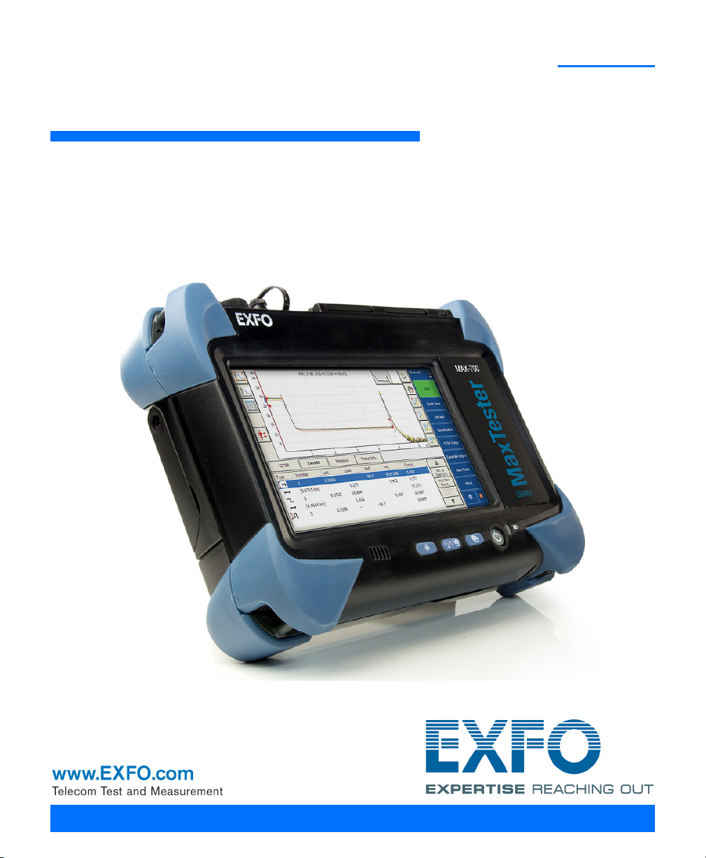
1 Introducing the MAX-700
The MAX-700 allows you to characterize a fiber-optic span, usually optical
fiber sections joined by splices and connectors. The optical time domain
reflectometer (OTDR) provides an inside view of the fiber, and can
calculate fiber length, attenuation, breaks, total return loss, and splice,
connector and total losses.
Note: In this documentation, the words “tap” and “double-tap” (related to the
use of a touchscreen) replace the words “click” and “double-click”.
Main Features
Your MAX-700 includes the following:
Multitasking possibilities
Seven-inch color touchscreen (LCD and touchscreen optimized for
outdoor use available as an option)
Two USB 2.0 ports (host)
Ethernet port (10/100/1000 Base-T)
Optional internal Wi-Fi and Bluetooth devices
Windows Embedded Standard operating system
Fiber inspection probe port
Optional built-in power meter and VFL
Remote access to your unit (via TightVNC)
Direct Web access from your unit
Possibility to take screen captures
PDF file generator and viewer available from your unit
Easy transfer of files and folders to a USB storage device
Easy updates for applications via Update Manager
Impressive dynamic range with short dead zones
MAX-700 1
Page 14
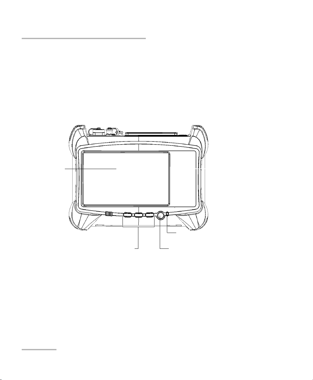
Introducing the MAX-700
Battery LED
Touchscreen
Front
On/Off button/Power LEDFunction buttons
Main Features
Possible to perform quick acquisitions with low noise levels to enable
accurate low-loss splice location.
Possible to acquire OTDR traces made of up to 256 000 points that
provide a sampling resolution as fine as 4 cm.
Possible to use the OTDR port as a light source.
2 MAX-700
Page 15
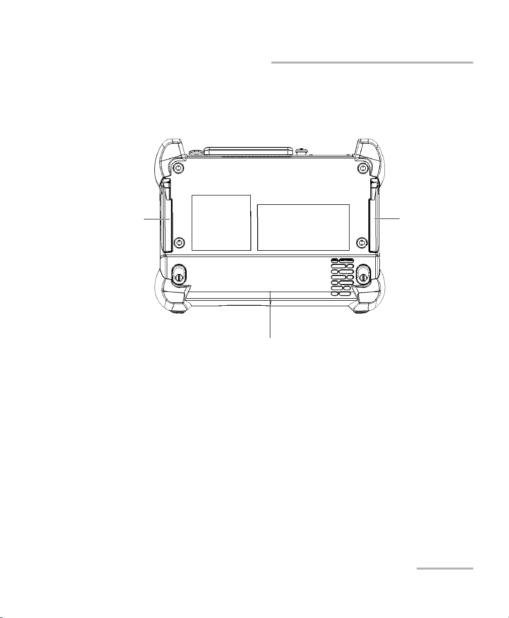
Introducing the MAX-700
Battery compartment
Support Support
Back
Main Features
MAX-700 3
Page 16
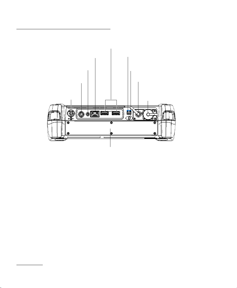
Introducing the MAX-700
USB host ports
AC adapter/charger
connector
Fiber inspection probe port
RJ-45 port
Headset/microphone port
Built-in power meter
(optional)
VFL (optional)
Top
Stylus
Internal Wi-Fi/Bluetooth devices
(optional; sticker indicates that
devices are present)
OTDR instrument
(see hereafter for details)
Main Features
4 MAX-700
Page 17
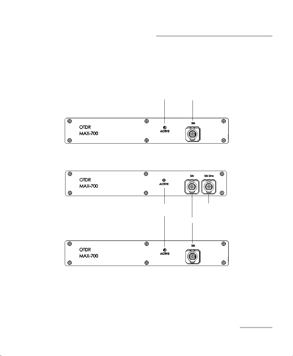
Introducing the MAX-700
MAX-710
OTDR port (singlemode)
Active LED
(on when laser is emitting)
OTDR Instrument
OTDR port (singlemode live)
MAX-730
OTDR port (singlemode)
Active LED
(on when laser is emitting)
Main Features
MAX-700 5
Page 18
Introducing the MAX-700
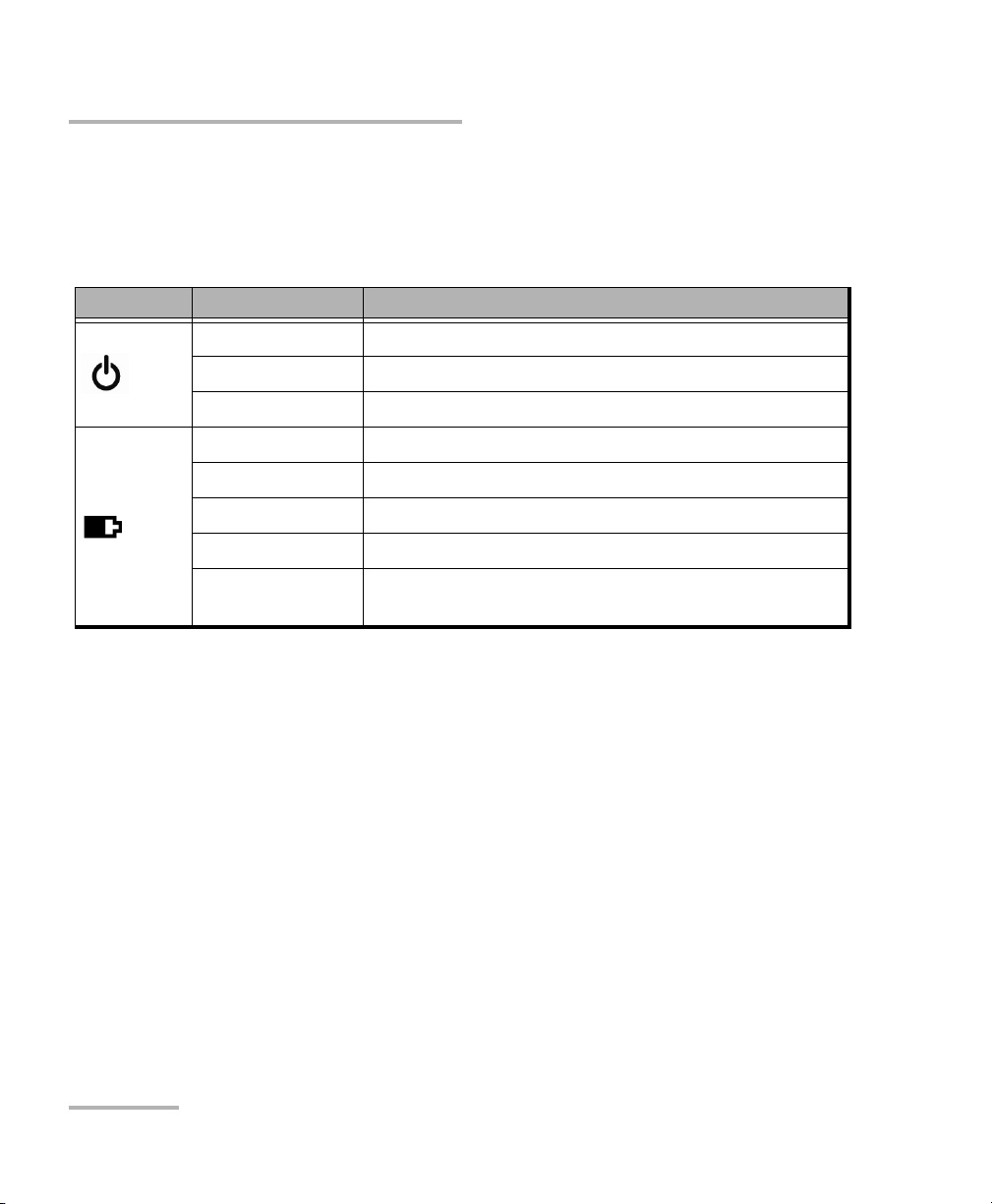
LED Indicators Description
LED Indicators Description
There are two LED indicators located on the front panel of your unit,
providing you with information about the power and battery statuses.
LED Status Meaning
Green Unit is on.
Green, blinking Unit is in Standby mode.
Off Unit is off or in Hibernation mode.
Green Battery is fully charged.
Green, blinking Battery is charging.
Yellow, blinking Unit is not powered by AC and battery is low.
Red No battery in the unit or battery error.
Off Unit is off or unit is not powered by AC and battery
level is above the “low-battery threshold”.
6 MAX-700
Page 19
Introducing the MAX-700
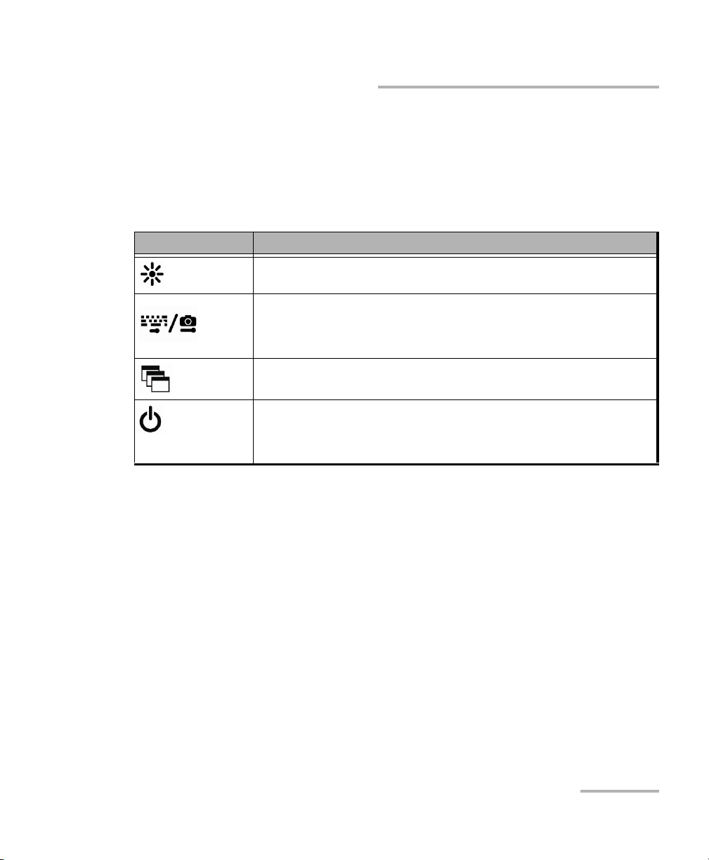
Function Buttons Description
Function Buttons Description
Your unit is equipped with function buttons which give you access to
various tools at all times.
The table below shows an overview of their purpose.
Button Meaning
Adjusts screen brightness (5 levels).
Displays the on-screen keyboard
Takes a screen capture (button held down for a few
seconds)
Enables you to switch from one task to another.
Turns your unit on and off.
For more information on the various ways to turn off your unit,
see Turning On or Off the Unit on page 24.
Trace Acquisition Modes
The OTDR application provides the following trace acquisition modes:
Auto: Automatically calculates fiber length, sets acquisition
parameters, acquires traces, and displays event tables and acquired
traces.
Advanced: Offers all the tools needed to perform integral OTDR tests
and measurements and gives you control over all test parameters.
Fault Finder: Rapidly locates fiber ends and displays the length of the
fiber under test. This allows you to perform quick tests without having
to set all the acquisition parameters.
MAX-700 7
Page 20

Introducing the MAX-700
Optional Software Package
Optional Software Package
An optional software package is offered with the application.
With the optional Auto Diagnostic (AD) software package you can:
Have access to the “linear view”, which displays the events
sequentially, from left to right.
Find macrobends and view the related information.
View the summary table, which gives, for each wavelength, the global
status of the results, the span loss and span ORL values.
Test in Fault Finder mode, to rapidly locate fiber ends.
Data Post-Processing
To view and analyze traces without the MAX-700 use a computer onto
which FastReporter is already installed.
8 MAX-700
Page 21

Introducing the MAX-700
Distance
c
n
---
t
2
---
=
OTDR Basic Principles
OTDR Basic Principles
An OTDR sends short pulses of light into a fiber. Light scattering occurs in
the fiber due to discontinuities such as connectors, splices, bends, and
faults. An OTDR then detects and analyzes the backscattered signals. The
signal strength is measured for specific intervals of time and is used to
characterize events.
The OTDR calculates distances as follows:
where
c = speed of light in a vacuum (2.998 x 10
t = time delay from the launch of the pulse to the reception of the
pulse
n = index of refraction of the fiber under test (as specified by the
manufacturer)
8
m/s)
MAX-700 9
Page 22
Introducing the MAX-700
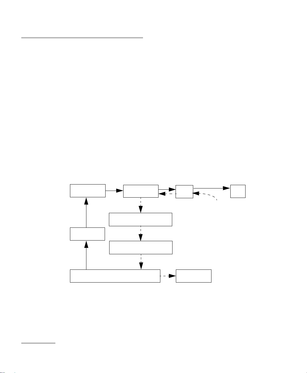
Microprocessor
Pulse
generator
Avalanche
photodetector (APD)
Display
Reflections come back
to the OTDR
Set of
instructions
Light pulses
Light pulses
Analog-to-digital
converter (A/D)
Returned signal
Analyzed signal
Laser
diode
Optical
coupler
OTDR
port
Fiber
OTDR Basic Principles
An OTDR uses the effects of Rayleigh scattering and Fresnel reflection to
measure the fiber’s condition, but the Fresnel reflection is tens of
thousands of times greater in power level than the backscatter.
Rayleigh scattering occurs when a pulse travels down the fiber and
small variations in the material, such as variations and discontinuities
in the index of refraction, cause light to be scattered in all directions.
However, the phenomenon of small amounts of light being reflected
directly back toward the transmitter is called backscattering.
Fresnel reflections occur when the light traveling down the fiber
encounters abrupt changes in material density that may occur at
connections or breaks where an air gap exists. A very large quantity of
light is reflected, as compared with the Rayleigh scattering. The
strength of the reflection depends on the degree of change in the index
of refraction.
When the full trace is displayed, each point represents an average of many
sampling points. You will have to zoom to see each point.
10 MAX-700
Page 23

Introducing the MAX-700
Power Sources
Power Sources
Your unit operates with the following power sources:
AC adapter/charger (connected to standard power outlet—indoor use
only). Compatible car outlet adapter available upon request.
One lithium-ion rechargeable battery (automatically takes over if you
disconnect the AC adapter/charger).
Note: When it is connected with the AC adapter/charger, the unit will function
even if the battery is not present.
Possible to switch from AC adapter/charger to battery power or
vice versa without affecting operation.
The battery recharges automatically when the AC adapter/charger
is connected.
Rechargeable battery (for clock). This battery can keep the date and
time for weeks even if AC power and the lithium-ion battery (main
battery) are not connected.
MAX-700 11
Page 24

Introducing the MAX-700
Conventions
Conventions
Before using the product described in this guide, you should understand
the following conventions:
Indicates a potentially hazardous situation which, if not avoided,
could result in death or serious injury. Do not proceed unless you
understand and meet the required conditions.
Indicates a potentially hazardous situation which, if not avoided,
may result in minor or moderate injury. Do not proceed unless you
understand and meet the required conditions.
Indicates a potentially hazardous situation which, if not avoided,
may result in component damage. Do not proceed unless you
understand and meet the required conditions.
WARNING
CAUTION
CAUTION
IMPORTANT
Refers to information about this product you should not overlook.
12 MAX-700
Page 25
2 Safety Information
WARNING
Do not install or terminate fibers while a light source is active.
Never look directly into a live fiber and ensure that your eyes are
protected at all times.
WARNING
The use of controls, adjustments and procedures other than those
specified herein may result in exposure to hazardous situations or
impair the protection provided by this unit.
IMPORTANT
When you see the following symbol on your unit , make sure
that you refer to the instructions provided in your user
documentation. Ensure that you understand and meet the required
conditions before using your product.
MAX-700 13
Page 26
Safety Information
Affixed to bottom panel of unit
Affixed to side panel
of unit
Laser Safety Information
Laser Safety Information
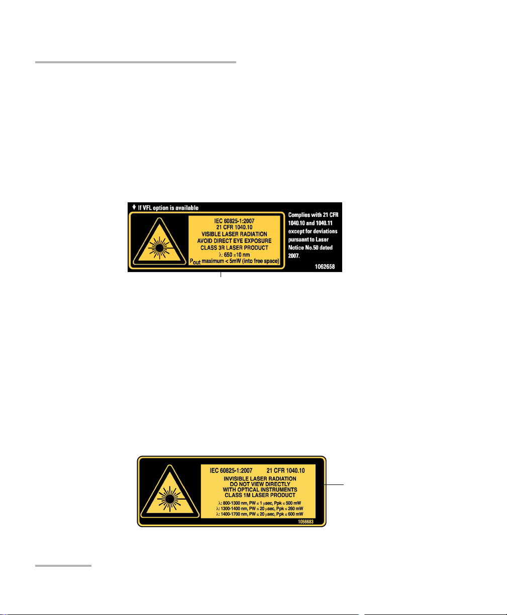
Units with Built-In VFL
Your instrument is a Class 3R laser product in compliance with standards
IEC 60825-1 and 21 CFR 1040.10. It is potentially harmful in direct
intrabeam viewing.
The following label(s) indicate that the product contains a Class 3R source:
Units without VFL
Your instrument is a Class 1M laser product in compliance with standards
IEC 60825-1 and 21 CFR 1040.10. Invisible laser radiation may be
encountered at the output port.
The product is safe under reasonably foreseeable conditions of operation
but it may be hazardous if you use optics within a diverging or collimated
beam. Do not view directly with optical instruments.
The following label(s) indicate that the product contains a Class 1M source:
14 MAX-700
Page 27

Safety Information
Electrical Safety Information
Electrical Safety Information
If you need to ensure that the unit is completely turned off, disconnect the
power cable and remove the batteries.
WARNING
Use the external power supply indoors only.Position the unit so
that the air can circulate freely around it.
Operation of any electrical instrument around flammable gases
or fumes constitutes a major safety hazard.
To avoid electrical shock, do not operate the unit if any part of
the outer surface (covers, panels, etc.) is damaged.
Only authorized personnel should carry out adjustments,
maintenance or repair of opened units under voltage. A person
qualified in first aid must also be present. Do not replace any
components while power cable and battery are connected.
Capacitors inside the unit may be charged even if the unit has
been disconnected from its electrical supply.
Use only the AC adapter/charger provided by EXFO with your
unit.
MAX-700 15
Page 28

Safety Information
Electrical Safety Information
Tem pe ra tu re
Operation
Storage
Relative humidity
unit
AC adapter
a
Equipment Ratings
0 °C to 50 °C (32 °F to 122 °F)
-40 °C to 70 °C (-40 °F to 158 °F)
95 % non-condensing
0 % to 80 % non-condensing
Maximum operation
5000 m (16405 ft)
altitude
Pollution degree 2 (when plugged to AC mains)
3 (when operated from batteries)
b
c
Overvoltage category II
Input power
unit
AC adapter
a. Measured in 0 °C to 31 °C (32 °F to 87.8 °F) range, decreasing linearly to 50 % at 40 °C (104 °F).
b. For indoor use only.
c. Equipment is normally protected against exposure to direct sunlight, precipitations and full wind
pressure.
d. Not exceeding ± 10 % of the nominal voltage.
d
24 V; 3.75 A
100 - 240 V; 50/60 Hz; 1.6 A
16 MAX-700
Page 29
3 Getting Started with Your
MAX-700
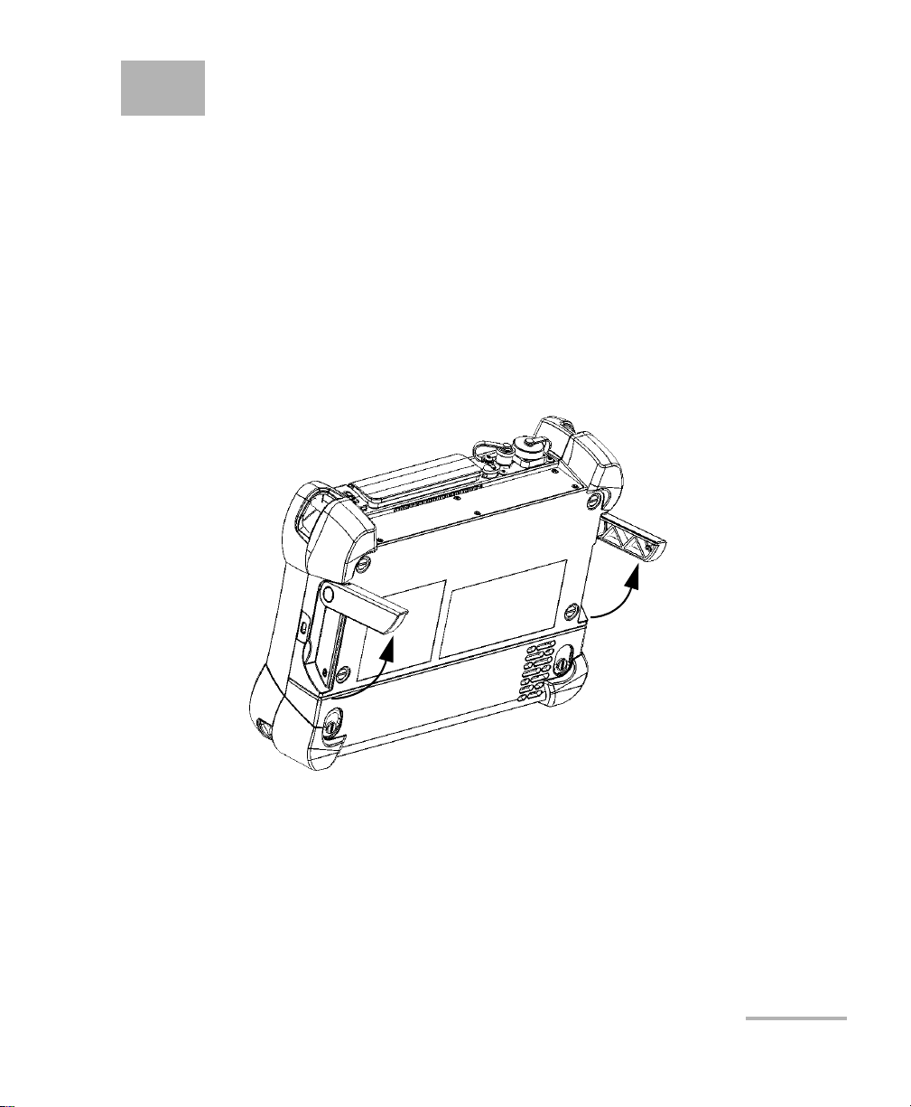
Using the Supports
Your unit has been designed to stand either vertically (with the screen
facing you), or at an angle, using the two supports.
Note: The supports ensure optimum stability to the unit during your tests.
To change the orientation of the unit using the supports:
Pull out the two supports.
MAX-700 17
Page 30
Getting Started with Your MAX-700
Securing Your Unit Using a Kensington Lock
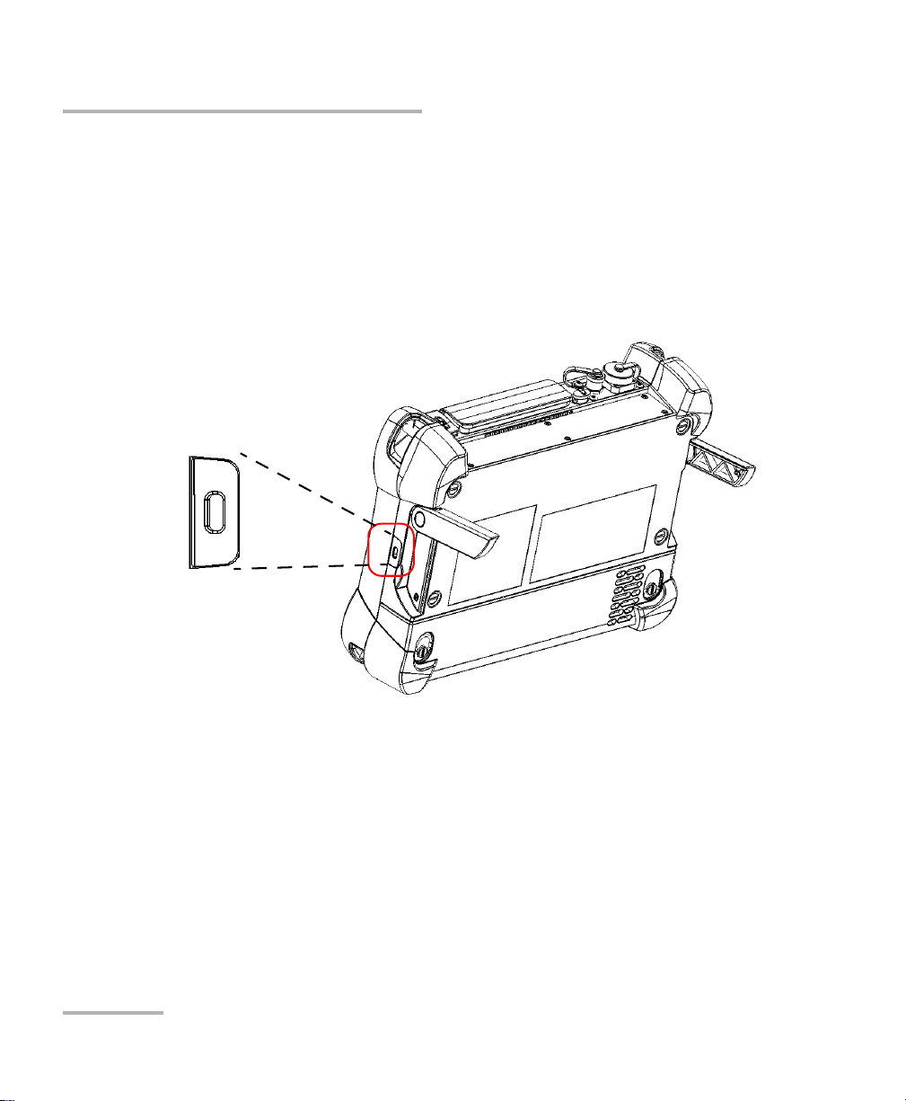
Securing Your Unit Using a Kensington Lock
Your unit is equipped with a security slot to which you can connect an
optional Kensington lock (security cable). You can secure your unit with
this lock to help prevent theft.
To secure your unit:
Connect your lock to the security slot located on the side of your unit.
18 MAX-700
Page 31

Getting Started with Your MAX-700
Installing a Keyboard, Mouse or Other USB Devices
Installing a Keyboard, Mouse or Other USB
Devices
Your unit supports many USB devices. The table below lists the supported
USB devices.
Device Details
Memory key For data transfer between your unit and a computer
when you do not have access to a network. If you
need information on how to transfer data using a
memory key, see Managing Data on page 255.
Keyboard When you are required to enter alphanumeric data,
an on-screen (virtual) keyboard is displayed. However,
if you prefer, you can use a hardware keyboard.
Note: Even if a keyboard is connected, the
on-screen keyboard will still be
displayed when you work in the
MAX-700 software.
Mouse If your prefer to use a mouse instead of the
touchscreen, you can install one.
MAX-700 19
Page 32

Getting Started with Your MAX-700
Installing a Keyboard, Mouse or Other USB Devices
Device Details
Composite device You can use composite devices, that is devices that
input information to your unit using more than one
mean (for example, combinations of keyboard and
mouse).
Hub This device will be particularly useful to you if you
need extra USB ports.
USB to RS-232
adapter
(purchased from
EXFO)
You can connect several devices at the same time.
To be able to transfer data between your unit and a
device only equipped with RS-232 (serial) ports. For
more information, see Using the USB to RS-232
Adapter on page 271.
IMPORTANT
Your unit does not support USB printers. If you want to print
documents, you must use PDFCreator or a network printer
(see Printing Documents on page 233), or transfer your files to a
computer (see Managing Data on page 255) that has access to a
network printer.
20 MAX-700
Page 33

Getting Started with Your MAX-700
Installing a Keyboard, Mouse or Other USB Devices
To install a USB device on your unit:
Connect the USB device to any of the USB ports (located on top of the
unit).
Note: It is not necessary to turn off the unit before connecting the USB device. The
software will automatically detect its presence.
Your device is automatically recognized and immediately usable.
MAX-700 21
Page 34

Getting Started with Your MAX-700
Using the On-Screen (Virtual) Keyboard
Using the On-Screen (Virtual) Keyboard
Your unit is equipped with an on-screen keyboard that supports
multilingual features. This keyboard functions according to the keyboard
settings of Windows.
To use the on-screen keyboard:
1. From the unit's front panel, press the button.
2. Select the location where you want to enter text.
3. Enter the data as required.
4. Exit the location when you have finished entering data.
22 MAX-700
Page 35

Getting Started with Your MAX-700
Right-Clicking with the Touchscreen
Right-Clicking with the Touchscreen
If you are used to work with a mouse, you may find it useful to be able to
perform a right-click on your touchscreen.
To right-click with the touchscreen:
From the location where you want to right-click, using the stylus or any
blunt pointing device, press the screen for a few seconds until the shortcut
menu appears.
If you want to hide the shortcut menu without performing any action,
simply tap anywhere outside the menu.
MAX-700 23
Page 36

Getting Started with Your MAX-700
Turning On or Off the Unit
Turning On or Off the Unit
There are several ways to turn off the unit, including the following:
Standby: keeps the unit’s status information in memory (RAM). The
next time you turn your unit on, you will quickly return to your work
environment (running applications will still be running).This mode will
take more battery power while the unit is off.
Shutdown: completely cuts power to the test modules and platform;
the unit will perform a complete restart routine the next time you use
it. You should perform a shutdown if you do not intend to use your unit
for a week or more.
After a shutdown, the unit will start in the MAX-700 software or in the
application you defined as the startup application.
Note: As it is the case for many computers, pressing and holding down the power
button for more than 10 seconds will perform a power down reset on the
unit.
By default, your unit will display the standard shutdown window from
which you can select the desired shutdown mode. However, you can
configure your unit to perform a different action when the power button is
pressed.
You can also configure your unit to automatically restart when AC power
comes back after the unit has turned off (emergency shutdown or standby
modes) when battery level is too low.
24 MAX-700
Page 37

Getting Started with Your MAX-700
Turning On or Off the Unit
To turn on the unit:
Press the On/Off button.
To turn off the unit:
1. Press the On/Off button.
OR
On the Windows taskbar, tap Start.
This will display the standard shutdown window, from which you have
a choice of actions or shutdown modes.
2. Select Shutdown.
To define the behavior of the power button:
1. From the Main Menu, tap Setup.Double-tap Power Options.
2. Select the Advanced tab.
MAX-700 25
Page 38

Getting Started with Your MAX-700
Turning On or Off the Unit
3. From the When I press the power button on my computer list, select
the desired behavior (Ask me what to do option is selected by
default).
4. Ta p Apply to confirm the changes, and then OK to return to Control
Panel.
26 MAX-700
Page 39

Getting Started with Your MAX-700
Turning On or Off the Unit
To configure your unit to automatically restart after AC power
comes back:
1. From the Main Menu, tap System Settings.
2. From the System Settings window, tap Startup Applications.
3. Select the Power on the unit when AC outlet is connected or after
power outage box to enable the corresponding option.
OR
Clear the box if you prefer that your unit does not restart automatically
after AC power comes back.
4. Tap to confirm the changes and return to the main window.
MAX-700 27
Page 40

Getting Started with Your MAX-700
Installing or Upgrading the Applications
Installing or Upgrading the Applications
All the necessary applications have been preinstalled and configured at the
factory. However, you may have to upgrade some applications when new
versions become available or to reinstall them.
From the DVD that came with your unit, you can create an installation USB
key in case you ever need to reinstall the MAX-700 software (the software
that comes with your unit) and the instrument applications as well as
Update Manager. All the necessary files will be copied to the USB key.
When updates are available for an application, you will need to download
them from Internet, either directly on your unit or on a computer. In the
latter case, you will need to transfer the update files to your unit
(see Managing Data on page 255). The update files must be copied to the
location that has been specified for the deployment packages in Update
Manager.
If you ever need to reinstall Update Manager on your unit, ensure
that:
IMPORTANT
The installation files for Update Manager remain on your unit.
Otherwise, it will not be possible to install new versions of this
application later.
You choose the folder containing the Update Manager
installation files carefully. If you move or rename this folder, you
will have to manually browse for the modified folder when you
want to install new versions of this application.
28 MAX-700
Page 41

Getting Started with Your MAX-700
Installing or Upgrading the Applications
For the creation of an installation USB key, you will need:
the installation DVD
a computer equipped with a USB port; Windows must be installed on
the computer
a USB memory key
For the upgrades, you will need:
a MAX-700 unit
a computer equipped with a USB port; Windows must be installed on
the computer
a USB memory key
Note: For the upgrades, the computer and USB key are only necessary if you do
not wish to download the files directly on your unit.
Note: For more information on the installation, refer to the Update Manager
online help.
MAX-700 29
Page 42

Getting Started with Your MAX-700
Installing or Upgrading the Applications
To update or reinstall Update Manager:
1. If necessary, retrieve the desired installation files from the Internet.
If you do not intend to download files directly on your unit, connect a
USB memory key to one of the USB ports of the computer and copy the
installation files to this USB key.
2. If it is not already done, turn on your unit.
3. Exit the MAX-700 software and the OTDR application.
4. If you want to install Update Manager using the USB key, disconnect it
from the computer and connect it to one of the USB ports of your unit.
5. On your unit, create a folder on the Windows desktop.
6. Copy the installation files (from the USB key) to the newly created
folder.
7. From the newly created folder, tap the Setup.exe file to start the
installation.
8. Follow the on-screen instructions.
9. When the installation is complete, simply disconnect the USB memory
key.
30 MAX-700
Page 43

Getting Started with Your MAX-700
Installing or Upgrading the Applications
To install or upgrade the applications:
1. If necessary, retrieve the desired installation files from the Internet.
If you do not intend to download files directly on your unit, connect a
USB memory key to one of the USB ports of the computer and copy the
installation files to this USB key.
2. If it is not already done, turn on your unit. If necessary, exit the OTDR
application.
3. If you want to install or update applications using the USB key,
disconnect it from the computer and connect it to one of the USB ports
of your unit.
4. Copy the installation files (from the USB key) to the folder containing
the update and installation packages on your unit. By default, Update
Manager will search for files at the root of the USB key. For more
information, refer to the Update Manager online help.
5. From the MAX-700 software, on your unit, select the Utilities tab.
6. Ta p Update Manager to start the corresponding application. For more
information on how to install or upgrade applications, refer to the
Update Manager online help.
7. When installation is complete, simply disconnect the USB memory
key.
MAX-700 31
Page 44

Getting Started with Your MAX-700
Installing or Upgrading the Applications
To create an installation USB key:
1. Turn on the computer and insert the installation DVD in the CD/DVD
drive.
2. Connect a USB memory key to one of the USB ports of the computer.
3. From the Welcome window on the installation DVD, click Installation
Files and Tools.
4. Select the MAX-700 Installation Files check box and click Next.
5. Follow the on-screen instructions. All the necessary components will
be copied to your USB key.
6. When the operation is complete, click Close, and then Exit to close the
installation DVD window.
7. Disconnect the USB memory key from the computer.
Your new installation USB key is now ready.
32 MAX-700
Page 45

Getting Started with Your MAX-700
Activating Software Options
Activating Software Options
The software options purchased at the same time as your unit have been
activated for you already. However, if you purchase options afterwards, you
will have to activate them yourself.
Before being able to activate options, you need to contact EXFO with the
following information:
Purchase order number of the newly purchased options
Instrument or unit (platform) serial number (depending on whether
the software options were purchased for the OTDR or the unit itself)
Customer's name
Customer’s company name
Customer’s phone number
Customer’s e-mail address
Instrument or unit on which the option will be installed
You will receive a single key (.key) file with which you will be able to
unlock all the new options that you have purchased.
MAX-700 33
Page 46

Getting Started with Your MAX-700
Activating Software Options
To activate the options for your unit:
1. Connect a USB memory key to one of the USB ports of your computer.
2. Copy the key file to the USB memory key.
3. Disconnect the USB key from the computer and connect it to your unit.
4. From the MAX-700, select the Utilities tab, then tap Options
Activation.
34 MAX-700
Page 47

Getting Started with Your MAX-700
Activating Software Options
5. In the Platform Options tab, use the Browse button to locate the key
file that you want to use.
6. Press Activate.
The option indicator will turn into a green check mark to confirm that
the option is now active.
7. Press OK to close the Option Activation window.
Note: At this point, if you have used a USB key to copy your key file, you can
remove it as it is not required to use your new options.
MAX-700 35
Page 48

Getting Started with Your MAX-700
Activating Software Options
To activate software options for your module:
1. Connect a USB memory key to one of the USB ports of your computer.
2. Copy the key file to the USB memory key.
3. Disconnect the USB key from the computer and connect it to your unit.
4. From the MAX-700, select the Utilities tab, then tap Options
Activation.
36 MAX-700
Page 49

Getting Started with Your MAX-700
Activating Software Options
5. In the Module Options tab, use the Browse button to locate the key
file that you want to use.
6. Press Activate.
The option indicator will turn into a green check mark to confirm that
the option is now active.
Note: You can see the supported options for the module in the Options list.
7. Press OK to close the Option Activation window.
Note: At this point, if you have used a USB key to copy your key file, you can
remove it as it is not required to use your new options.
MAX-700 37
Page 50

Getting Started with Your MAX-700
Applications
related directly to
the OTDR
Starting Instrument Applications
Starting Instrument Applications
Your OTDR can be configured and controlled from its dedicated
application in the MAX-700 software.
To start an application:
At the bottom of the main window, press the button corresponding to the
desired application.
38 MAX-700
Page 51

Getting Started with Your MAX-700
Data
display
Function
Ta bs
Button bar
Timer
To start the Power Meter or Probe application:
From Main Menu, press Power Meter or Probe.
The main window (shown below) contains all the commands required to
control the OTDR instrument:
Note: Due to screen resolution, the appearance of your OTDR application may
vary slightly from the illustrations presented in this user guide.
Timer
Once the acquisition has begun, a timer is displayed on the right-hand side
of the screen, indicating the remaining time until the next acquisition.
MAX-700 39
Page 52

Page 53

4 Preparing Your MAX-700 for a
Bare metal
(or blue border)
indicates UPC
option
Green border
indicates APC
option
2 3 4
Test
Installing the EXFO Universal Interface (EUI)
The EUI fixed baseplate is available for connectors with angled (APC) or
non-angled (UPC) polishing. A green border around the baseplate
indicates that it is for APC-type connectors.
To install an EUI connector adapter onto the EUI baseplate:
1. Hold the EUI connector adapter so the dust cap opens downwards.
2. Close the dust cap in order to hold the connector adapter more firmly.
3. Insert the connector adapter into the baseplate.
4. While pushing firmly, turn the connector adapter clockwise on the
baseplate to lock it in place.
MAX-700 41
Page 54

Preparing Your MAX-700 for a Test
Cleaning and Connecting Optical Fibers
Cleaning and Connecting Optical Fibers
To ensure maximum power and to avoid erroneous readings:
Always inspect fiber ends and make sure that they are clean as
explained below before inserting them into the port. EXFO is
not responsible for damage or errors caused by bad fiber
cleaning or handling.
Ensure that your patchcord has appropriate connectors. Joining
mismatched connectors will damage the ferrules.
To connect the fiber-optic cable to the port:
1. Inspect the fiber using a fiber inspection microscope. If the fiber is
clean, proceed to connecting it to the port. If the fiber is dirty, clean it as
explained below.
2. Clean the fiber ends as follows:
IMPORTANT
2a. Gently wipe the fiber end with a lint-free swab dipped in isopropyl
alcohol.
2b. Use compressed air to dry completely.
2c. Visually inspect the fiber end to ensure its cleanliness.
42 MAX-700
Page 55

Preparing Your MAX-700 for a Test
Cleaning and Connecting Optical Fibers
3. Carefully align the connector and port to prevent the fiber end from
touching the outside of the port or rubbing against other surfaces.
If your connector features a key, ensure that it is fully fitted into the
port’s corresponding notch.
4. Push the connector in so that the fiber-optic cable is firmly in place,
thus ensuring adequate contact.
If your connector features a screwsleeve, tighten the connector
enough to firmly maintain the fiber in place. Do not overtighten, as this
will damage the fiber and the port.
Note: If your fiber-optic cable is not properly aligned and/or connected, you will
notice heavy loss and reflection.
EXFO uses good quality connectors in compliance with EIA-455-21A
standards.
To keep connectors clean and in good condition, EXFO strongly
recommends inspecting them with a fiber inspection probe before
connecting them. Failure to do so will result in permanent damage to the
connectors and degradation in measurements.
MAX-700 43
Page 56

Preparing Your MAX-700 for a Test
Naming Trace Files Automatically
Naming Trace Files Automatically
Each time you start an acquisition, the application suggests a file name
based on autonaming settings. This file name appears on the upper part of
the graph and the linear view.
The file name is made of a static part (alphanumeric) and a variable part
(numeric) that will be incremented or decremented, according to your
selection, as follows:
If you choose incrementation... If you choose decrementation...
Variable part increases until it
reaches the highest possible value
with the selected number of digits
(for example, 99 for 2 digits), then
restarts at 0.
After saving a result, the unit prepares the next file name by incrementing
(or decrementing) the suffix.
Note: If you choose not to save a particular trace file, the suggested file name will
remain available for the next trace you acquire.
If you deactivate the automatic file naming function, the application will
prompt you to specify a file name. The default file name is Unnamed.trc.
By default, traces are saved in native (.trc) format, but you can configure
your unit to save them in Bellcore (.sor) format (see Selecting the Default
File Format on page 95).
Note: If you select the Bellcore (.sor) format, the unit will create one file per
wavelength (for example, TRACE001_1310.sor and TRACE001_1550.sor, if
you included both 1310 nm and 1550 nm in your test). The native format
contains all wavelengths in a single file.
Variable part decreases until it
reaches 0, then restarts at the highest
possible value with the selected
number of digits (for example, 99 for
2 digits).
44 MAX-700
Page 57

Preparing Your MAX-700 for a Test
To configure the automatic file naming:
1. From the button bar, press OTDR Setup.
2. Select the Acquisition tab.
3. Press Default Trace Information.
Naming Trace Files Automatically
MAX-700 45
Page 58

Preparing Your MAX-700 for a Test
Number of digits
composing the
variable part
Value at which the
autonumbering
sequence starts
The variable part will
increase or decrease
depending on your
choice
Naming Trace Files Automatically
4. Fill out the required information in the corresponding boxes and select
the direction for your trace files.
5. Press the button appearing next to the Fiber ID box to change the
contents of the fiber identification.
6. Change the criteria as needed, then press OK to confirm your new
settings and return to the Default Trace Information window.
46 MAX-700
Page 59

Preparing Your MAX-700 for a Test
This preview is
updated
automatically as you
make your selections
Items that can be
included in the file
name
To select the separator in
the automatic
numbering section
To add personalized
information not included
in the filename criteria
To modify the order of appearance of the
selected components in the file name
Naming Trace Files Automatically
7. Press File Autonaming to set up the trace file name options.
8. In the File Name window, select the desired components to include in
the file name. You can change the order of apparition with the up and
down arrow buttons.
MAX-700 47
9. Press OK to confirm your new settings.
Page 60

Preparing Your MAX-700 for a Test
Enabling or Disabling the First Connector Check
Enabling or Disabling the First Connector
Check
Note: This function is available in all OTDR modes. However, the first connector
check parameter used in Fault Finder mode is independent from the one
used in the other OTDR modes (Auto and Advanced).
The first connector check feature is used to verify that the fibers are
properly connected to the OTDR. It verifies the injection level and displays
a message when an unusually high loss occurs at the first connection,
which could indicate that no fiber is connected to the OTDR port. By
default, this feature is not enabled.
Note: The first connector check is only performed when you test at singlemode
wavelengths.
To enable or disable the first connector check:
1. From the Main Menu, press OTDR Setup then press the General tab.
2. To enable the first connector check, select the First connector check
box.
OR
To disable it, clear the box.
48 MAX-700
Page 61

Preparing Your MAX-700 for a Test
Setting Macrobend Parameters
Setting Macrobend Parameters
Note: This function is available with the Auto Diagnostic (AD) optional software
package only.
Note: This function is available both in Advanced and Auto modes.
Your unit can locate macrobends by comparing the loss values measured
at a certain location, for a certain wavelength (for example, 1310 nm) with
the loss values measured at the corresponding location, but for a greater
wavelength (for example, 1550 nm).
The unit will identify a macrobend when comparing two loss values if:
Of the two loss values, the greater loss occurred at the greater
wavelength.
AND
The difference between the two loss values exceeds the defined delta
loss value. The default delta loss value is 0.5 dB (which is suitable for
most fibers), but you can modify it.
You can also disable macrobend detection.
Note: Macrobend detection is only possible with singlemode wavelengths.
Filtered wavelengths or wavelengths of dedicated OTDR ports are not
available for macrobend detection.
For information on how the information about macrobends is available
after an acquisition, see Linear View on page 110 and Summary Table on
page 112.
MAX-700 49
Page 62

Preparing Your MAX-700 for a Test
Setting Macrobend Parameters
To set macrobend parameters:
1. From the Main Menu, press OTDR Setup then select the General tab.
2. To enable the macrobend detection, select the Show macrobend
check box.
OR
To disable it, clear the check box.
3. If necessary, set the delta value as follows:
3a. From the Wavelengths list, select the pair of wavelengths for
which you want to define the delta value.
Only the combinations of wavelengths your module can support
will be available.
For more significant results, EXFO recommends to always select
the combination of wavelengths including the smallest possible
wavelength and the greatest wavelength (for example, if your
module supports 1310 nm, 1550 nm, and 1625 nm, you would
select the 1310 nm/1625 nm combination).
3b. In the Delta (loss) box, enter the desired value.
3c. Repeat steps 3a and 3b for all combinations of wavelengths.
To revert to default settings:
1. Press Default.
2. When the application prompts you, answer Yes if you want to apply the
settings to all combinations of wavelengths.
50 MAX-700
Page 63

5 Testing Fibers in Auto Mode
Auto mode automatically evaluates fiber length, sets acquisition
parameters, acquires traces, and displays event tables and acquired traces.
In Auto mode, you can set the following parameters directly:
Test w avel e ngth s (all selected by default)
Fiber type (singlemode, singlemode live, or multimode) for models
supporting these fiber types
Autorange acquisition time
IOR (group index), RBS coefficient and helix factor
For all other parameters, the application uses those defined in Advanced
mode, except that analysis is always performed after acquisitions.
If you ever need to modify other parameters, go to Advanced mode (see
Testing Fibers in Advanced Mode on page 55 and Preparing Your MAX-700
for a Test on page 41).
In Auto mode, the application will automatically evaluate the best settings
according to the fiber link currently connected to the unit (in less than
5 seconds). If you interrupt it, no data will be displayed.
Fiber characteristics are evaluated only once per session. Other fibers you
connect to, within the same cable, will be tested with the same settings.
When you start testing another link, you can reset these parameters.
Once this evaluation is complete, the application starts acquiring the trace.
The trace display is continually updated.
Note: You can interrupt the acquisition at any time. The application will display
the information acquired to that point.
MAX-700 51
Page 64

Testing Fibers in Auto Mode
Event
pane
Tra ce
display
Once the acquisition is complete or interrupted, the analysis starts for
acquisitions of 5 seconds or more.
After analysis, the trace is displayed and events appear in the events table.
The application will also display status messages if you have selected to
display pass/fail messages (see Setting Pass/Fail Thresholds on page 70).
You can save the trace after analysis. If former results have not been saved
yet, the application prompts you to save them before starting a new
acquisition.
52 MAX-700
Page 65

Testing Fibers in Auto Mode
To acquire traces in Auto mode:
1. Clean the connectors properly.
2. Connect a fiber to the OTDR port.
If your unit is equipped with two OTDR ports, ensure that you connect
the fiber to the appropriate port (singlemode, singlemode live, or
multimode), depending on the wavelength you intend to use.
CAUTION
Never connect a live fiber to the OTDR port without a proper setup.
Any incoming optical power ranging from –65 dBm to –40 dBm will
affect the OTDR acquisition. The way the acquisition will be
affected depends on the selected pulse width.
Any incoming signal greater than 10 dBm could damage your
MAX-700 permanently. For live-fiber testing, refer to the SM Live
port specifications for the characteristics of the built-in filter.
3. Set the autorange acquisition time (see Setting the Autorange
Acquisition Time on page 60).
4. Go to the OTDR tab.
5. If your OTDR supports singlemode, singlemode live, or multimode
wavelengths, under Wavelengths, from the list, select the desired fiber
type (for live-fiber testing, select SM Live; for C fiber, select 50 μm and
for D fiber, select 62.5 μm).
MAX-700 53
Page 66

Testing Fibers in Auto Mode
6. Select the boxes corresponding to the desired test wavelengths. You
must select at least one wavelength.
7. If you want to clear the settings the OTDR has determined to start with
a new set of OTDR settings, press Reset.
8. Press Start.
If the first connector check feature is enabled, a message will appear if
there is a problem with the injection level (see Enabling or Disabling
the First Connector Check on page 48).
9. Once the analysis is complete, save the trace by pressing Quick Save
in the button bar.
The application will use a file name based on the autonaming
parameters you defined (see Naming Trace Files Automatically on
page 44). This file name appears at the top of the graph and at the top
of the linear view table.
Note: The application will only display the Save File dialog box if you have
activated the feature to always be prompted when you save a file. From
this dialog box, you can change the location, the file name and the file
format.
9a. If necessary, change the folder to which the file will be saved by
pressing the Location button.
9b. If necessary, specify a file name.
IMPORTANT
If you specify the name of an existing trace, the original file will be
overwritten and only the new file will be available.
10. Press OK to confirm.
54 MAX-700
Page 67

6 Testing Fibers in Advanced
Mode
Advanced mode offers all the tools you need to perform complete OTDR
tests and measurements manually and gives you control over all test
parameters.
Note: Most parameters can only be set if you select Advanced mode first. Once
you have finished selecting your settings, you can simply return to the test
mode you prefer.
By default, in Advanced mode, all available test wavelengths are selected.
In this mode, you can either set the acquisition parameters yourself or let
the application determine the most appropriate values.
In the latter case, the application will automatically evaluate the best
settings according to the fiber link currently connected to the unit:
The pulse width will be determined using a factory-defined
signal-to-noise ratio (SNR) requirement specified where the
End-of-Fiber (EoF) event has been detected.
The EoF event detection algorithm uses the end-of-fiber threshold
defined in the tab of the application setup. If you are not sure about
which value to choose, revert to the factory default value for this
parameter.
The range will then be set automatically. This optimum value may
differ from the values currently associated with the Distance dial of the
main window. In this case, the application will “add” the required
value and mark it with a * symbol.
The application uses the acquisition time defined in the Acquisition
tab of the OTDR setup (for more information, see Setting the Autorange
Acquisition Time on page 60). The default value is 15 seconds. Longer
acquisitions give better OTDR results.
MAX-700 55
Page 68

Testing Fibers in Advanced Mode
Event
pane
Tra ce
display
Although the application sets the acquisition parameters, you can modify
these values as needed, even while the acquisition is in progress. The
OTDR simply restarts the averaging each time a modification is made.
Note: You can interrupt the acquisition at any time. The application will display
the information acquired to that point.
Once the acquisition is complete or interrupted, the analysis starts for
acquisitions of 5 seconds or more.
After analysis, the trace is displayed. Events appear both in the events table
and in the linear view (if you purchased the optional software package).
The application will also display pass/fail messages if you have selected
this feature. For more information, see Setting Pass/Fail Thresholds on
page 70.
You can save the trace after analysis. If former results have not been saved
yet, the application prompts you to save them before starting a new
acquisition.
56 MAX-700
Page 69

Testing Fibers in Advanced Mode
To acquire traces:
1. Clean the connectors properly (see Cleaning and Connecting Optical
Fibers on page 42).
2. Connect a fiber to the OTDR port.
If your unit is equipped with two OTDR ports, ensure that you connect
the fiber to the appropriate port (singlemode, singlemode live, or
multimode), depending on the wavelength you intend to use.
CAUTION
Never connect a live fiber to the OTDR port without a proper setup.
Any incoming optical power ranging from –65 dBm to –40 dBm will
affect the OTDR acquisition. The way the acquisition will be
affected depends on the selected pulse width.
Any incoming signal greater than 10 dBm could damage your
MAX-700 permanently. For live-fiber testing, refer to the SM Live
port specifications for the characteristics of the built-in filter.
3. If you want the application to provide automatic acquisition values, set
the autorange acquisition time (see Setting the Autorange Acquisition
Time on page 60).
4. If you want to set your own IOR (group index), RBS coefficient or helix
factor, see Setting the IOR, RBS Coefficient, and Helix Factor on
page 61.
5. Go to the OTDR tab.
6. If you want to test in high resolution, simply select the feature (see
Enabling the High-Resolution Feature on page 66).
MAX-700 57
Page 70

Testing Fibers in Advanced Mode
7. If your OTDR supports singlemode, singlemode live, or multimode
wavelengths, under Wavelengths, from the list, select the desired fiber
type (for live-fiber testing, select SM Live; for C fiber, select 50 μm and
for D fiber, select 62.5 μm).
8. Select the boxes corresponding to the desired test wavelengths. You
must select at least one wavelength.
9. Select the desired distance, pulse, and time values. For more
information, see Setting Distance Range, Pulse Width, and Acquisition
Time on page 63.
10. Press Start. If the first connector check feature is enabled, a message
will appear if there is a problem with the injection level (see Enabling
or Disabling the First Connector Check on page 48).
You can modify the acquisition parameters as needed, while the
acquisition is in progress. The OTDR simply restarts the averaging each
time a modification is made.
58 MAX-700
Page 71

Testing Fibers in Advanced Mode
11. Once the analysis is complete, save the trace by pressing Quick Save
in the button bar.
The application will use a file name based on the autonaming
parameters you defined (see Naming Trace Files Automatically on
page 44). This file name appears at the top of the graph and at the top
of the linear view table.
Note: The application will only display the Save File dialog box if you have
activated the feature to always be prompted when you save a file. From
this dialog box, you can change the location, the file name and the file
format.
11a.If necessary, change the folder to which the file will be saved by
pressing the Location button.
11b.If necessary, specify a file name.
IMPORTANT
If you enter the name of an existing trace, the original file will be
replaced with the new file.
12. Press OK to confirm.
MAX-700 59
Page 72

Testing Fibers in Advanced Mode
Setting the Autorange Acquisition Time
Setting the Autorange Acquisition Time
Note: This function is available both in Advanced and Auto modes.
When performing automatic acquisitions in Advanced mode (see Testing
Fibers in Advanced Mode on page 55) or before activating Auto mode (see
Testing Fibers in Auto Mode on page 51), you can set an autorange
acquisition time for the OTDR to average acquisitions over a set time
period.
The application uses this value to determine the best settings for the test.
To set the autorange acquisition time:
1. From the button bar, press OTDR Setup then go to the Acquisition tab.
2. Go to the Autorange acquisition time box and press the up or down
arrow to select your preference. The default value is 30 seconds.
3. Press Exit OTDR Setup to return to the OTDR application.
60 MAX-700
Page 73

Testing Fibers in Advanced Mode
Setting the IOR, RBS Coefficient, and Helix Factor
Setting the IOR, RBS Coefficient, and Helix
Factor
Note: This function is available both in Advanced and Auto modes.
You sho uld set the IOR (g r ou p in dex ) , RBS coefficient and helix factor
before performing tests in order to apply them to all newly acquired traces.
However, if you are in Advanced mode, you can also set them at a later
time in the Trace Info. tab to reanalyze a specific trace.
The index of refraction (IOR) value (also known as group index) is
used to convert time-of-flight to distance. Having the proper IOR is
crucial for all OTDR measurements associated with distance (event
position, attenuation, section length, total length, etc.). IOR is provided
by the cable or fiber manufacturer.
The test application determines a default value for each wavelength.
You can set the IOR value for each available wavelength. You should
verify this information before each test.
The Rayleigh backscatter (RBS) coefficient represents the amount of
backscatter in a particular fiber. The RBS coefficient is used in the
calculation of event loss and reflectance, and it can usually be
obtained from the cable manufacturer.
The test application determines a default value for each wavelength.
You can set the RBS coefficient for each available wavelength.
The helix factor takes into consideration the difference between the
length of the cable and the length of the fiber inside the cable. Fibers
within a cable are spiraling around the cable core. The helix factor
describes the pitch of that spiral.
By setting the helix factor, the length of the OTDR distance axis is
always equivalent to the physical length of the cable (not the fiber).
MAX-700 61
Page 74

Testing Fibers in Advanced Mode
Wavelength for which
RBS and IOR will be
defined
Index of refraction
Rayleigh backscatter
coefficient
Setting the IOR, RBS Coefficient, and Helix Factor
To set the IOR, RBS, and helix factor parameters:
1. From the button bar, press OTDR Setup.
2. From the OTDR Setup window, go to the Acquisition tab.
3. Use the up or down arrow located on the side of the wavelength box to
select the desired wavelength.
IMPORTANT
Change the default RBS coefficient only if you have values provided
by the fiber manufacturer. If you set this parameter incorrectly, your
reflectance measurements will be inaccurate.
4. Select the default settings by pressing Default. When the application
prompts you, answer Yes only if you want to apply the new settings to
all wavelengths.
OR
Enter your own values in the boxes, for each available wavelength.
Note: You cannot define a different helix factor for each wavelength. This value
takes into account the difference between the length of the cable and the
length of the fiber inside the cable; it does not vary with wavelengths.
62 MAX-700
5. Press Exit OTDR Setup.
Page 75

Testing Fibers in Advanced Mode
Setting Distance Range, Pulse Width, and Acquisition Time
Setting Distance Range, Pulse Width, and
Acquisition Time
The distance range, pulse width and acquisition time are set with the
controls in the Advanced main window.
Distance: corresponds to the distance range of the fiber span to be
tested according to the selected measurement units (see Selecting the
Distance Units on page 99).
Changing the distance range alters the available settings of the pulse
width and leaves only the settings available for the specified range. You
can select either Auto or one of the predefined values.
You can customize the available distance range values (see
Customizing the Acquisition Distance Range Values on page 101). If
you select Auto, the application will evaluate the fiber length and set
the acquisition parameters accordingly.
Pulse: corresponds to the pulse width for the test. A longer pulse
allows you to probe further along the fiber, but results in less
resolution. A shorter pulse width provides higher resolution, but less
distance range. The available distance ranges and pulse widths
depend on your OTDR model.
Note: Not all pulse widths are compatible with all distance ranges.
You can select either Auto or one of the predefined values.
If you select Auto, the application will evaluate the fiber type and length
and set the acquisition parameters accordingly.
MAX-700 63
Page 76

Testing Fibers in Advanced Mode
Setting Distance Range, Pulse Width, and Acquisition Time
Time: corresponds to the acquisition duration (period during which
results will be averaged). Generally, longer acquisition times generate
cleaner traces (this is especially true with long-distance traces)
because as the acquisition time increases, more of the noise is
averaged out. This averaging increases the signal-to-noise ratio (SNR)
and the OTDR’s ability to detect small events.
The time settings will also determine how the timer (displayed in the
toolbar) counts time during testing (see Timer on page 39).
If the predefined values do not suit your needs, you can customize one
or all of them. For more information, see Customizing the Acquisition
Time Values on page 103.
In addition to the displayed values, the following time modes are
available:
Real: used to immediately view changes in the fiber under test. In
this mode, the SNR of the trace is lower and the trace is refreshed
instead of averaged until you press Stop.
You can alternate between real mode and averaging time interval
mode while an acquisition is in progress.
Note: The Real item will be available if only one wavelength is selected.
Auto: the application will use the autorange acquisition time that
you have previously defined (see Setting the Autorange Acquisition
Time on page 60). It will also evaluate the fiber type and length and
set the acquisition parameters accordingly.
You can use the same distance range, pulse width and acquisition time
parameters for testing at all wavelengths on a multiwavelength OTDR.
IMPORTANT
To test using the high-resolution feature, the acquisition time must
be of at least 15 seconds.
64 MAX-700
Page 77

Testing Fibers in Advanced Mode
Parameter-setting dials
Selection
marker
Setting Distance Range, Pulse Width, and Acquisition Time
To set the parameters:
From the OTDR tab:
Press the dial corresponding to the parameter you wish to set (the
selection marker will move clockwise).
OR
Press directly the value to select it. The selection marker will go to that
value immediately.
If you want the application to provide automatic acquisition values, move
at least one dial to the Auto position. The other dials are automatically set
accordingly.
Note: If your OTDR supports singlemode, singlemode live, or multimode
wavelengths, settings would be applied to either singlemode, singlemode
live, or multimode wavelengths, depending on the selected fiber type
(same settings for 50 μm and 62.5 μm).
MAX-700 65
Page 78

Testing Fibers in Advanced Mode
Enabling the High-Resolution Feature
To use the same pulse and acquisition time for all wavelengths:
1. From the button bar, press OTDR Setup, then go to the Acquisition
tab.
2. Select the Apply settings to all wavelengths box.
The modifications you make to pulse, time, and range settings will now be
applied to all wavelengths.
Enabling the High-Resolution Feature
You can select the high-resolution feature to obtain more data points per
acquisition. This way, the data points will be closer to each other, which
will result in a greater distance resolution for the trace.
Note: When you test with the high-resolution feature, you should use a longer
averaging time to maintain a signal-to-noise ratio (SNR) that will be
equivalent to the one you would have got with the standard resolution.
Note: You can use high resolution with any test mode (except when you monitor
fiber in real time), but you must be in Advanced mode to select it.
IMPORTANT
To test using the high-resolution feature, the acquisition time must
be of at least 15 seconds.
66 MAX-700
Page 79

Testing Fibers in Advanced Mode
Enabling the High-Resolution Feature
To enable the high-resolution feature:
1. From the button bar, press OTDR Setup.
2. Go to the Acquisition tab.
3. Select the High-resolution acquisition box.
Note: If your OTDR supports singlemode, singlemode live, or multimode
wavelengths, the high-resolution feature will be activated either for the
singlemode, singlemode live, or multimode wavelengths, depending on the
selected fiber type.
4. Press Exit OTDR Setup to return to the main window.
MAX-700 67
Page 80

Testing Fibers in Advanced Mode
Enabling or Disabling Analysis After Acquisition
Enabling or Disabling Analysis After
Acquisition
The OTDR trace acquisition procedure will be completed by the analysis.
You can either choose to automatically analyze each trace immediately
after the acquisition, or perform the analysis whenever it suits you best.
When the analysis process is disabled, the Event table of a newly acquired
trace will be empty.
You can also set a default fiber span, which will be applied during the
analysis of all traces to display test results. For details, see Setting a Default
Span Start and Span End on page 75.
Note: In Auto mode, the application always performs an analysis after the
acquisition.
68 MAX-700
Page 81

Testing Fibers in Advanced Mode
Enabling or Disabling Analysis After Acquisition
To enable or disable the analysis after trace acquisition:
1. From the button bar, press OTDR Setup.
2. Go to the Analysis tab.
3. If you want the OTDR to automatically analyze an acquired trace,
select the Automatically analyze data after acquisition box.
If you clear the check box, the trace will be acquired without being
analyzed.
Note: By default, traces are automatically analyzed as they are acquired.
4. Press Exit OTDR Setup to return to the main window.
MAX-700 69
Page 82

Testing Fibers in Advanced Mode
Setting Pass/Fail Thresholds
Setting Pass/Fail Thresholds
You can activate and set Pass/Fail threshold parameters for your tests.
You can set thresholds for splice loss, connector loss, reflectance, fiber
section attenuation, span loss, span length, and span ORL. You can apply
the same pass/fail thresholds to all test wavelengths or apply them
separately to each one.
You can set different pass/fail thresholds for each available test
wavelength. These pass/fail thresholds will be applied to the analysis
results of all newly acquired traces with the corresponding wavelength.
By default, the application provides threshold values for the following
wavelengths: 1310 nm, 1383 nm, 1390 nm, 1410 nm, 1490 nm, 1550 nm,
1625 nm, and 1650 nm. However, if you work with files containing other
wavelengths, the application will automatically add these custom
wavelengths to the list of available wavelengths. You will then be able to
define thresholds for these new wavelengths. You can revert all thresholds
to their default values, except if they are associated with custom
wavelengths.
The loss, reflectance and attenuation thresholds that you set are applied to
all events where such values can be measured. Setting these thresholds
allows you either to ignore events with known lower values, or to ensure
that all events are detected—even the ones for which very small values are
measured.
70 MAX-700
Page 83

Testing Fibers in Advanced Mode
Setting Pass/Fail Thresholds
The following table provides the default, minimum and maximum
thresholds.
Test Default Minimum Maximum
Splice loss (dB) 1.000 0.015 5.000
Connector loss (dB) 1.000 0.015 5.000
Fiber section attenuation (dB/km) 0.400 0.000 5.000
Once the thresholds are set, the application will be able to perform
Pass/Fail tests to determine the status of the various events (pass or fail).
The Pass/Fail test is performed on two occasions:
when analyzing or reanalyzing a trace
when you open a trace file
Values that are greater than the predefined thresholds are displayed in
white on a red background in the events table.
The Pass/Fail threshold LED, located on the front of the unit, will also
indicate the status (green for pass, red for fail).
You can also set the application to display pass/fail messages when the
Pass/Fail test is performed.
MAX-700 71
Page 84

Testing Fibers in Advanced Mode
Threshold to set
Value associated
with the
threshold to set
Setting Pass/Fail Thresholds
To set pass/fail thresholds:
1. From the button bar, select OTDR Setup, then select the Event Table
tab.
2. From the Wa vel e ngth list, select the wavelength for which you want to
set thresholds.
3. Select the boxes corresponding to the thresholds that you want to use,
and enter the desired values in the appropriate fields.
Note: If you no longer want the application to take into account a particular
threshold, simply clear the corresponding box.
4. If you want the application to display messages when events fail the
test, select Display Pass/Fail message.
72 MAX-700
Page 85

Testing Fibers in Advanced Mode
Setting Pass/Fail Thresholds
5. If you want to apply the thresholds you have just defined to one or
several other wavelengths, proceed as follows:
5a. Press the Copy to Other Wavelengths button.
5b. Select the boxes corresponding to the wavelengths for which you
want to use the same thresholds.
Note: You can use the Select All button to quickly select all boxes at the same
time.
5c. Press OK to confirm you selection.
6. Press Exit OTDR Setup to return to the main window.
MAX-700 73
Page 86

Testing Fibers in Advanced Mode
Setting Pass/Fail Thresholds
To revert to default threshold values and to delete custom
wavelengths:
1. From the button bar, select OTDR Setup, then select the Event Table
tab.
2. Press the Revert to Factory Settings button.
3. When the application prompts you, confirm the modification with Yes.
All threshold values of all wavelengths are returned to their default values,
except for thresholds that are associated with custom wavelengths.
When you revert thresholds to their default values, custom
wavelengths will be deleted from the list of available wavelengths,
except if a file using at least one of these wavelengths is still open.
IMPORTANT
74 MAX-700
Page 87

Testing Fibers in Advanced Mode
Setting a Default Span Start and Span End
Setting a Default Span Start and Span End
By default, the span start and span end of a fiber are assigned, respectively,
to the first event (the launch level event) and the last event (often a
non-reflective or reflective end event) of a trace.
You can change the default fiber span that will be applied during the initial
trace analysis.
You can set the span start and span end on a particular event or at a certain
distance value from the beginning or end of the trace. You can even define
a fiber span for short fibers by placing the span start and the span end on
the same event.
By default, the number of available events is set to 10 and, therefore,
does not necessarily reflect the actual number of events displayed.
When you set a distance value for the span start or end, the application
searches for a nearby event. If it finds one, the span start or end is
assigned to that event, rather than at the exact distance you have set.
Changes to the span start and span end will modify the contents of the
events table. The span start becomes event 1 and its distance reference
becomes 0. Events excluded from the fiber span are grayed out in the
events table, and do not appear in the trace display. The cumulative loss is
calculated within the defined fiber span only.
Note: You can also change the fiber span of a single trace after the analysis and
reanalyze the trace (see Analyzing or Reanalyzing a Trace on page 155).
However, if you want to keep working with the original parameters, you
must reenter them.
MAX-700 75
Page 88

Testing Fibers in Advanced Mode
Setting a Default Span Start and Span End
To change the default span start and span end for traces:
1. From the button bar, press OTDR Setup.
2. From the OTDR Setup window, go to the Analysis tab.
3. If you want to set the span start and end with a distance value, under
Span start and Span end, select Set by distance.
Go to the Position box and enter the desired value, using the distance
units displayed to the right of the box.
Under Span end, indicate whether the span end position is from the
fiber span start or from the end of the fiber.
OR
If you want to set the span start and end on a particular event, under
Span start and Span end, select Set on event.
From the Event number list, use the up or down arrow to select the
number of the event that you want to designate as span start or span
end.
The span event parameters are applied to all newly acquired traces.
76 MAX-700
Page 89

7 Testing Fibers in Fault Finder
Mode
The application offers you a special testing feature to rapidly locate fiber
ends. It also displays the length of the fiber under test.
This could be useful if you want to perform a quick test without having to
set all the acquisition parameters.
Acquiring Traces in Fault Finder Mode
The unit will determine the more appropriate wavelength (singlemode or
multimode, depending on your test configuration). It will use the default
IOR (group index), RBS coefficient, and helix factor. The duration of
acquisition is 45 seconds.
To acquire traces in Fault finder mode:
1. Clean the connectors properly (see Cleaning and Connecting Optical
Fibers on page 42).
2. Connect a fiber to the OTDR port.
If your unit is equipped with two OTDR ports, ensure that you connect
the fiber to the appropriate port (singlemode, singlemode live, or
multimode), depending on the wavelength you intend to use.
CAUTION
Never connect a live fiber to the OTDR port without a proper setup.
Any incoming optical power ranging from –65 dBm to –40 dBm will
affect the OTDR acquisition. The way the acquisition will be
affected depends on the selected pulse width.
Any incoming signal greater than 10 dBm could damage your
MAX-700 permanently. For live-fiber testing, refer to the SM Live
port specifications for the characteristics of the built-in filter.
MAX-700 77
Page 90

Testing Fibers in Fault Finder Mode
Acquiring Traces in Fault Finder Mode
3. From the Port list, specify to which port you connected your fiber.
4. Press Start. If the first connector check feature is enabled, a message
will appear if there is a problem with the injection level (see Enabling
or Disabling the First Connector Check for Fault Finder on page 87).
78 MAX-700
Page 91

Testing Fibers in Fault Finder Mode
Acquiring Traces in Fault Finder Mode
5. Once the analysis is complete, save the trace by pressing Quick Save
in the button bar.
The application will use a file name based on the autonaming
parameters you defined (see Naming Fault Finder Files Automatically
on page 80). This file name appears at the top of the graph.
Note: The application will only display the Save File dialog box if you have
activated the feature to always be prompted when you save a file and if
you did not disable the storage features. From the Save File dialog box, you
can change the location, the file name and the file format.
5a. If necessary, change the folder to which the file will be saved by
pressing the Location button.
5b. If necessary, specify a file name.
IMPORTANT
If you specify the name of an existing trace, the original file will be
overwritten and only the new file will be available.
5c. Press OK to confirm.
MAX-700 79
Page 92

Testing Fibers in Fault Finder Mode
Naming Fault Finder Files Automatically
Naming Fault Finder Files Automatically
Each time you start an acquisition, the Fault Finder application suggests a
file name based on autonaming settings. This file name appears on the
upper part of the graph.
Note: The autonaming settings used in Fault Finder mode are independent from
those used in Auto or Advanced modes. File names are built following the
same principle, but there is one set of settings for Fault Finder and one set
of settings for the other OTDR modes.
The file name is made of a static part (alphanumeric) and a variable part
(numeric) that will be incremented or decremented, according to your
selection, as follows:
If you choose incrementation... If you choose decrementation...
Variable part increases until it
reaches the highest possible value
with the selected number of digits
(for example, 99 for 2 digits), then
restarts at 0.
After saving a result, the unit prepares the next file name by incrementing
(or decrementing) the suffix.
Note: If you choose not to save a particular trace file, the suggested file name will
remain available for the next trace you will acquire.
By default, traces are saved in native (.trc) format, but you can configure
your unit to save them in Bellcore (.sor) format (see Selecting the Default
File Format for the Fault Finder Traces on page 82).
80 MAX-700
Variable part decreases until it
reaches 0, then restarts at the highest
possible value with the selected
number of digits (for example, 99 for
2digits).
Page 93

Testing Fibers in Fault Finder Mode
Number of digits composing
the variable part
Static part Variable part (incremented)
The value appearing in this box will be used in
the next file name.
File name extension
(corresponds to the current file
format)
Naming Fault Finder Files Automatically
To configure the automatic file naming:
1. From the button bar, press Setup.
2. From the Setup window, select the General tab then press the File
Autonaming button.
3. From the Autonaming Setup dialog box, set the parameters.
If you want the variable part to increase each time a file is saved, select
Increment. If you want it to decrease, select Decrement.
4. Press OK to confirm your new settings.
MAX-700 81
Page 94

Testing Fibers in Fault Finder Mode
Selecting the Default File Format for the Fault Finder Traces
Selecting the Default File Format for the Fault
Finder Traces
You can define the default file format the Fault Finder application will use
when you save your traces.
Note: The default file format used in Fault Finder mode are independent from the
file format used in Auto or Advanced modes. There is one default file
format for Fault Finder and one default file format for the other OTDR
modes.
By default, traces are saved in native (.trc) format, but you can configure
your unit to save them in Bellcore (.sor) format.
You can only modify the file format from the Save File dialog box, which
means you need to save at least one trace in the desired format before it
becomes the new default file format.
Note: The application will only display this dialog box if you have activated the
feature to always be prompted when you save a file (see Enabling or
Disabling the Confirmation of Fault Finder File Name on page 84) and if
you did not disable the storage features.
82 MAX-700
Page 95

Testing Fibers in Fault Finder Mode
Selecting the Default File Format for the Fault Finder Traces
To select the default file format:
1. From the button bar, press Quick Save.
2. From the Save File dialog box, select the desired format.
3. Press OK to save your file in the new format. The next files will be
saved in the new format.
MAX-700 83
Page 96

Testing Fibers in Fault Finder Mode
Enabling or Disabling the Confirmation of Fault Finder File Name
Enabling or Disabling the Confirmation of
Fault Finder File Name
By default, each time you save a file, the application prompts you to
confirm the file name.
Note: The file name confirmation parameter used in Fault Finder mode is
independent from the one used in the other OTDR modes (Auto and
Advanced).
The application will use a file name based on autonaming settings
(see Naming Fault Finder Files Automatically on page 80).
If you prefer to hide the Quick Save button, see Enabling or Disabling the
Storage Feature on page 86.
84 MAX-700
Page 97

Testing Fibers in Fault Finder Mode
Enabling or Disabling the Confirmation of Fault Finder File Name
To enable or disable file name confirmation:
1. From the button bar, press Setup, then go to the General tab.
2. If you want to confirm file name each time you press Quick Save,
select the Always show confirmation window on save check box.
OR
If you never want to be prompted, clear the check box.
Note: You can also disable the confirmation of the file name by clearing the
Always show this window on save check box directly from the Save File
dialog box.
3. Press Exit Setup to return to the main window. The changes are
applied automatically.
MAX-700 85
Page 98

Testing Fibers in Fault Finder Mode
Enabling or Disabling the Storage Feature
Enabling or Disabling the Storage Feature
By default, the Quick Save button is displayed in the button bar. However,
if you only want to perform quick tests without having to save the results,
you may prefer to hide the Quick Save button.
To enable or disable the storage feature:
1. From the button bar, press Setup, then go to the General tab.
2. If you want to hide the Quick Save button, select the
Disable storage features check box.
OR
If you want to display the button, clear the check box.
3. Press Exit Setup to return to the main window. The changes are
applied automatically.
86 MAX-700
Page 99

Testing Fibers in Fault Finder Mode
Enabling or Disabling the First Connector Check for Fault Finder
Enabling or Disabling the First Connector
Check for Fault Finder
The first connector check feature is used to verify that the fibers are
properly connected to the OTDR. It verifies the injection level and displays
a message when a unusually high loss occurs at the first connection, which
could indicate that no fiber is connected to the OTDR port. By default, this
feature is not enabled.
Note: The first connector check is only performed when you test at singlemode
wavelengths.
Note: The first connector check parameter used in Fault Finder mode is
independent from the one used in the other OTDR modes (Auto and
Advanced).
MAX-700 87
Page 100

Testing Fibers in Fault Finder Mode
Enabling or Disabling the First Connector Check for Fault Finder
To enable or disable the first connector check:
1. From the button bar, press Setup then select the General tab.
2. To enable the first connector check, select the First connector check
check box.
OR
To disable it, clear the check box.
3. Press Exit Setup to return to the main window. The changes are
applied automatically.
88 MAX-700
 Loading...