

Page 1
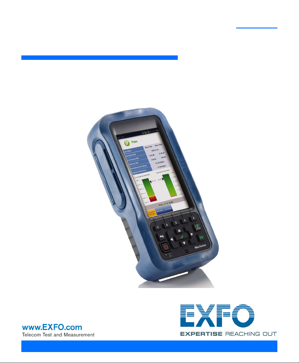
MaxTester 630
VDSL2/ADSL2+ Multi-play Test Set
User Guide
Page 2

Copyright Information
Copyright Information
Copyright © 2010–2014 EXFO Inc. All rights reserved. No part of this
publication may be reproduced, stored in a retrieval system or transmitted
in any form, be it electronically, mechanically, or by any other means such
as photocopying, recording or otherwise, without the prior written
permission of EXFO Inc. (EXFO).
Information provided by EXFO is believed to be accurate and reliable.
However, no responsibility is assumed by EXFO for its use nor for any
infringements of patents or other rights of third parties that may result from
its use. No license is granted by implication or otherwise under any patent
rights of EXFO.
EXFO’s Commerce And Government Entities (CAGE) code under the North
Atlantic Treaty Organization (NATO) is 0L8C3.
The information contained in this publication is subject to change without
notice.
Trademarks
EXFO’s trademarks have been identified as such. However, the presence
or absence of such identification does not affect the legal status of any
trademark.
Units of Measurement
Units of measurement in this publication conform to SI standards and
practices.
Version number 8.0.0
ii MAX-630
Page 3

Contents
Contents
Copyright Information ............................................................................................................ii
Certification Information ........................................................................................................v
1 Introducing the MaxTester 630 ................................................................... 1
Key Features and Benefits .......................................................................................................1
Typical Applications ................................................................................................................1
Using the MaxTester ...............................................................................................................2
Cable Connections ..................................................................................................................5
Conventions ............................................................................................................................6
2 Safety Information ....................................................................................... 7
Electrical Safety .....................................................................................................................8
Equipment Ratings .................................................................................................................9
3 Getting Started with the MaxTester ......................................................... 11
Turning the Unit On/Off ........................................................................................................11
Using Menus and Keypad .....................................................................................................12
Keypad ..................................................................................................................................13
Using Online Help .................................................................................................................14
4 Setting Up the MAX-630 ............................................................................. 15
Home ....................................................................................................................................15
System Settings ....................................................................................................................16
Display and Language ...........................................................................................................17
Date and Time ......................................................................................................................18
Power ...................................................................................................................................19
Software Options ..................................................................................................................22
Information ..........................................................................................................................23
Upload Setup ........................................................................................................................24
5 Setting Up DSL/IP Tests .............................................................................. 31
DSL Main Menu Page ............................................................................................................31
Test Configuration ................................................................................................................32
Test Setup .............................................................................................................................43
Setup ....................................................................................................................................55
VDSL2/ADSL2+ Multi-play Test Set iii
Page 4

Contents
6 Running DSL/IP Tests and Viewing Results ................................................67
DSL/IP Connection Summary .................................................................................................67
Ethernet Connection Summary .............................................................................................69
WAN Status ..........................................................................................................................70
LAN Status ............................................................................................................................71
VoIP Call ...............................................................................................................................72
VoIP Summary ......................................................................................................................78
IPTV Summary ......................................................................................................................79
Join Leave .............................................................................................................................81
DSL Parameter Details ...........................................................................................................82
DSL Statistics ........................................................................................................................85
Band Information .................................................................................................................88
Loop Diagnostics ..................................................................................................................89
Data Tests Summary .............................................................................................................90
Web Browser ........................................................................................................................92
Bookmarks ............................................................................................................................94
7 Saving, Reading, and Exporting DSL/IP Test Results .................................95
Saving Results .......................................................................................................................95
Read/Export Results ............................................................................................................100
8 Maintenance ..............................................................................................103
General Maintenance ..........................................................................................................103
Recalibrating the Unit .........................................................................................................104
Battery ................................................................................................................................106
Recycling and Disposal (Applies to European Union Only) ..................................................108
9 Troubleshooting ........................................................................................109
Solving Common Problems .................................................................................................109
LED Statuses .......................................................................................................................111
Contacting the Technical Support Group ............................................................................112
Transportation ....................................................................................................................113
10 Warranty ....................................................................................................115
General Information ...........................................................................................................115
Liability ...............................................................................................................................116
Exclusions ...........................................................................................................................117
Certification ........................................................................................................................117
Service and Repairs .............................................................................................................118
EXFO Service Centers Worldwide ........................................................................................119
...........................................................................................................................................119
A Technical Specifications ............................................................................121
iv MAX-630
Page 5

Certification Information
Certification Information
North America Regulatory Statement
This unit was certified by an agency approved in both Canada and the
United States of America. It has been evaluated according to applicable
North American approved standards for product safety for use in Canada
and the United States.
Electronic test and measurement equipment is exempt from FCC part 15,
subpart B compliance in the United States of America and from ICES-003
compliance in Canada. However, EXFO Inc. makes reasonable efforts to
ensure compliance to the applicable standards.
The limits set by these standards are designed to provide reasonable
protection against harmful interference when the equipment is operated in
a commercial environment. This equipment generates, uses, and can
radiate radio frequency energy and, if not installed and used in accordance
with the user guide, may cause harmful interference to radio
communications. Operation of this equipment in a residential area is likely
to cause harmful interference in which case the user will be required to
correct the interference at his own expense.
Modifications not expressly approved by the manufacturer could void the
user's authority to operate the equipment.
VDSL2/ADSL2+ Multi-play Test Set v
Page 6

Certification Information
Page 1 of 1
DECLARATION OF CONFORMITY
Application of Council Directive(s): 2004/108/EC – The EMC Directive
1999/5/EC – The R&TTE Directive
93/68/EEC – CE Marking
And their amendments
Manufacturer’s Name and Address:
EXFO Inc. EXFO Europe
400 Godin Avenue Omega Enterprise Park, Electron Way
Quebec City, Quebec Chandlers Ford, Hampshire
G1M 2K2 CANADA SO53 4SE ENGLAND
Tel.: +1 418 683-0211 Tel.: +44 2380 246810
Equipment Type/Environment: Test & Measurement / Industrial
Trade Name/Model No.: ADSL2+/VDSL2 Multiplay Testing / MaxTester 630
Standard(s) to which Conformity is declared:
EN 61010-1:2001 Edition 2.0
Safety requirements for electrical equipment for measurement,
control, and laboratory use
– Part 1: General requirements
EN 61326-1:2006
Electrical equipment for measurement, control and laboratory use –
EMC requirements
– Part 1: General requirements
I, the undersigned, hereby declare that the equipment specified above conforms to the above Directive and Standards.
Manufacturer:
Stephen Bull, E. Eng
Vice-President Research and Development
400 Godin Avenue,
Quebec City, Quebec
G1M 2K2 CANADA
June 4, 2012
European Community Declaration of Conformity
vi MAX-630
Page 7

1 Introducing the MaxTester 630
The MAX-630 is a handheld device designed for testing ADSL2+ and VDSL2
services between the service provider and the subscriber premises. In
addition, the dual Ethernet ports of the MAX-630 allow it to be used inside
the home to test all the way to the end point of the service.
The MaxTester 630 test set case is an aluminum enclosure with rubber over
mold, which makes it ideal for field use. Its display is a back-lit LCD
featuring 480 x 800 resolution. A membrane keypad mounted on the face
of the unit features a 14-button keypad used to operate the test set. The
following describes the features of the MAX-630.
Key Features and Benefits
Broadcom chipset
IP login
DSL testing
User-defined automatic testing
Dual Ethernet ports
Customer modem replacement
Color display with graphical analysis
Battery powered
Rugged and weatherproof handheld unit
Typical Applications
ADSL2+ and VDSL2 testing
Optional ADSL2+ and VDSL2 bonding support
Supports Ping, FTP, and Traceroute tests with optional support for Web
Browser and IPTV analysis
Ethernet testing for qualifying FTTx service at the customer premises
Configurable pass/fail results for automated testing
VDSL2/ADSL2+ Multi-play Test Set 1
Page 8
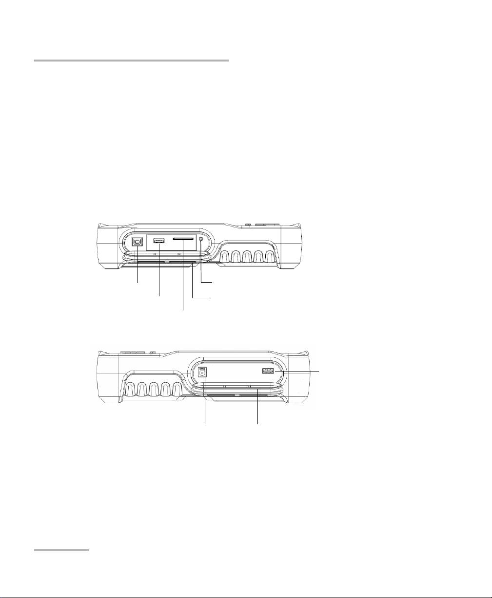
Introducing the MaxTester 630
USB Host Port
USB Client Port
SD Card (not used)
Head Set Jack (2.5 mm)
Door
DC Power Door
USB Client Port
Using the MaxTester
Using the MaxTester
The MaxTester is tested IEC IP54 which means that it is not affected by dust
or water splashing against the enclosure from any direction. This
protection is only valid when both side doors are properly closed. If the
equipment is used in a manner not specified by the manufacturer, the
protection provided by the equipment may be impaired.
The MaxTester is equipped with a series of interfaces shown in the
following views:
Left
Right
2 MAX-630
Page 9
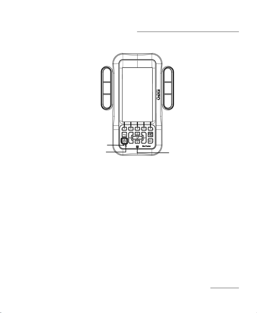
Front
Power LED
Battery LED Speaker
Introducing the MaxTester 630
Using the MaxTester
VDSL2/ADSL2+ Multi-play Test Set 3
Page 10

Introducing the MaxTester 630
Battery Door
Screws
Screws
Using the MaxTester
Back
Note: The MAX-630 enclosure may become warm during normal use.
4 MAX-630
Page 11
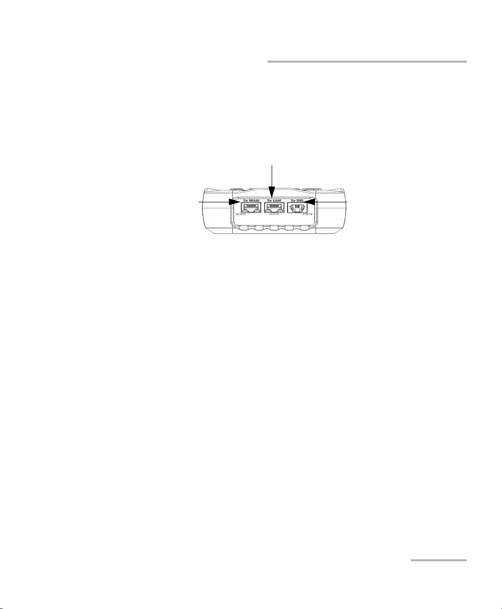
Introducing the MaxTester 630
Ethernet LAN port
Ethernet WAN port
DSL port
Cable Connections
Cable Connections
The graphics below show the connectors on the MAX-630 device.
Note: When connecting a DSL cable to the DSL port, use the RJ-11 plug end of the
26 AWG cable provided with the unit. There is a 1500 V maximum transient
voltage on telecom ports. Basic insulation is needed for external telecom
circuits.
Note: For the connection setup, Annex B is on DSL pair 1 and Annex A is on pair 2.
(Dual Annex A and B units only)
VDSL2/ADSL2+ Multi-play Test Set 5
Page 12

Introducing the MaxTester 630
Conventions
Conventions
Before using the product described in this guide, you should understand
the following conventions:
Indicates a potentially hazardous situation which, if not avoided,
could result in death or serious injury. Do not proceed unless you
understand and meet the required conditions.
Indicates a potentially hazardous situation which, if not avoided,
may result in minor or moderate injury. Do not proceed unless you
understand and meet the required conditions.
Indicates a potentially hazardous situation which, if not avoided,
may result in component damage. Do not proceed unless you
understand and meet the required conditions.
WARNING
CAUTION
CAUTION
IMPORTANT
Refers to information about this product you should not overlook.
6 MAX-630
Page 13

2 Safety Information
WARNING
The use of controls, adjustments and procedures other than those
specified herein may result in exposure to hazardous situations or
impair the protection provided by this unit.
IMPORTANT
When you see the following symbol on your unit , make sure
that you refer to the instructions provided in your user
documentation. Ensure that you understand and meet the required
conditions before using your product.
IMPORTANT
Other safety instructions relevant for your product are located
throughout this documentation, depending on the action to
perform. Make sure to read them carefully when they apply to your
situation.
VDSL2/ADSL2+ Multi-play Test Set 7
Page 14

Safety Information
Electrical Safety
Electrical Safety
The AC adapter/charger provided with this unit (18 W/9 V) is specifically
designed to work with your MaxTester.
Use the AC/DC adapter/charger indoors only.
Use only with a Class II AC/DC adapter, power limited output.
On the AC/DC adapter, replacing detachable mains supply cords
with inadequately rated cords, may result in overheating of the
cord and create a fire risk.
The adapter shall have the appropriate safety mark (e.g. UL,
CSA, TUV, CE, etc.) that is acceptable to the authorities in the
country where the equipment is to be used.
When using the MaxTester while connected to the AC/DC
adapter/charger, make sure you do not position the equipment so
that it is difficult to disconnect the adapter/charger from the
AC mains.
WARNING
CAUTION
WARNING
Use only accessories that meet EXFO specifications.
8 MAX-630
Page 15

Equipment Ratings
Tem pe rat ur e
Operation
Storage
Relative humidity
unit
AC adapter
0 °C to 40 °C (32 °F to 104 °F)
–40 °C to 70 °C (–40 °F to 158 °F)
a
95 % non-condensing
0 % to 80 % non-condensing
Safety Information
Equipment Ratings
Equipment Ratings
Maximum operation
3000 m (9842 ft)
altitude
Pollution degree 2 (when plugged to AC mains)
3 (when operated from batteries)
b
c
Overvoltage category II
Input power
unit
AC adapter
a. Measured in 0 °C to 31 °C (32 °F to 87.8 °F) range, decreasing linearly to 50 % at 40 °C
(104 °F).
b. For indoor use only.
c. Equipment is normally protected against exposure to direct sunlight, precipitations and
full wind pressure.
d. Not exceeding ± 10 % of the nominal voltage.
d
9-24 V; 18 W; 1.67 A
100 - 240 V; 50/60 Hz; 0.7 A
VDSL2/ADSL2+ Multi-play Test Set 9
Page 16

Page 17

3 Getting Started with the
MaxTester
Turning the Unit On/Off
When you turn the unit on, you may use it immediately under normal
conditions. When the unit is turned off, it keeps the following parameters
in its internal memory:
Setup including system, application, and modem settings.
Profiles consisting of:
Test parameters
User-defined thresholds
Regional, LCD and energy-saving settings
Test results saved internally vs. USB
There are two ways to turn off the MaxTester
Suspend: the next time you turn your unit on, you will quickly return to
your work environment.
Shutdown: completely cuts power to the unit; the unit will perform a
complete restart routine the next time you use it. You should perform a
shutdown if you do not intend to use your unit for a few hours or more.
To turn the unit on:
Press to start. The unit initializes for a few seconds and displays the
Home pane.
VDSL2/ADSL2+ Multi-play Test Set 11
Page 18

Getting Started with the MaxTester
Using Menus and Keypad
To enter suspend mode:
Press for about 2 seconds. The MaxTester will stay in suspend mode for
2 hours, after which it will automatically shutdown. This prevents complete
battery discharge and ensures maximum battery performance.
To perform a shutdown:
Hold down for about 4 seconds. The shutdown process starts.
Note: In both previous cases, if the power adapter is connected, the MaxTester
will simulate either a fake suspend or fake shutdown in order to facilitate
the charger.
Using Menus and Keypad
You can access various tools from the keypad or menu. Menu options may
differ depending on your unit configuration.
Home menu is where you can access Copper Test, DSL/IP Tests, or
System Settings.
Each test has a sub menu.
To navigate through the items, use the arrow keys.
To confirm a choice or enter a menu, press .
To cancel an action or return to the previous item or pane, press .
To return to the home pane, press .
Press once to return to the Main test menu or twice to return to the
Home page.
Note: Pressing
while a test is running will do nothing. The test can not be
running in order to return to the main menu screen.
Note: You can also select an option directly by pressing the function keys
corresponding to the on-screen buttons at the bottom of the screen.
12 MAX-630
Page 19
Getting Started with the MaxTester
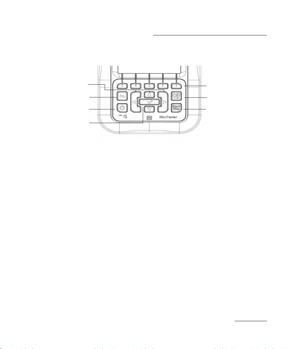
Function keys
Home/Help
Start/Stop test
Power
Back
Arrow keys
Enter
Keypad
Power button on the lower left side of the unit is used to power the unit
on and off.
Arrow keys navigate the screen to access and modify parameters.
Function keys activate the corresponding on-screen function button.
Keypad
Home button brings you to the Home page of the MAX-630.
VDSL2/ADSL2+ Multi-play Test Set 13
Page 20

Getting Started with the MaxTester
Using Online Help
Using Online Help
Online help is available at any time. Most test operations pause while you
view help, but will resume automatically when you exit help.
To access help about the current function at any time:
Press and hold the ? key.
14 MAX-630
Page 21
4 Setting Up the MAX-630
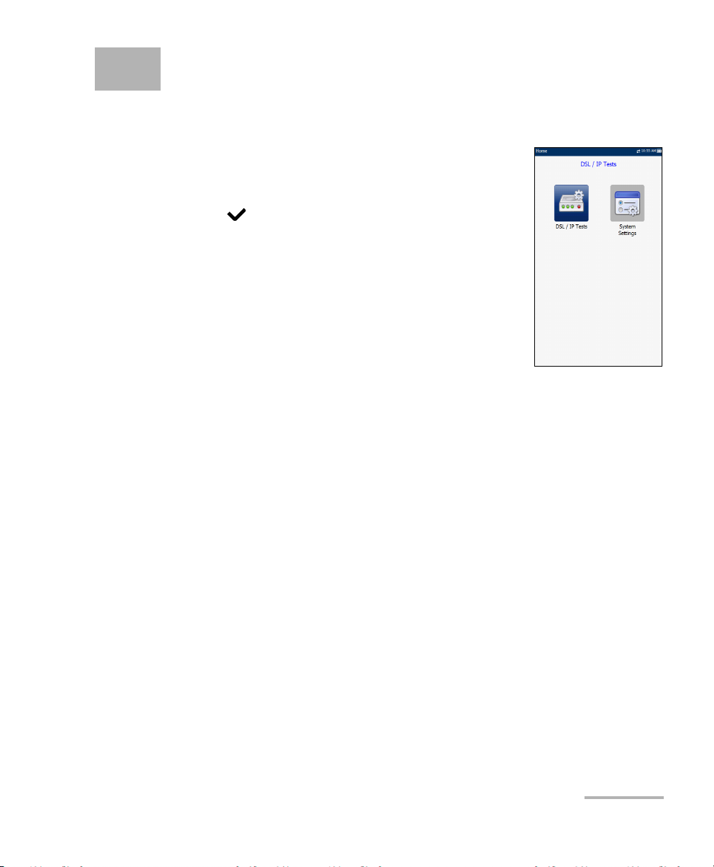
Home
Home presents the main menu page which allows
you to navigate between DSL/IP Tests and System
Settings using the left/right arrow keys on the keypad.
Press to bring up the sub-menu of the selected
icon:
DSL/IP Tests opens the DSL Main menu for
ADSL2+, VDSL2, and multi-play services testing
applications.
System Settings allow you to set the parameters
of the unit and access to Upload Setup.
VDSL2/ADSL2+ Multi-play Test Set 15
Page 22
Setting Up the MAX-630
System Settings
System Settings
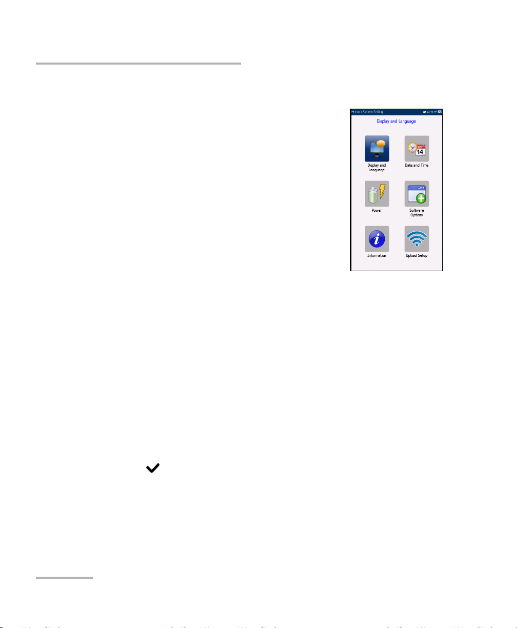
System Settings presents a menu of items to setup
the unit.
Display and Language provides the setup for
backlight, information on the title bar, and
language choice.
Date and Time sets the date and time and format.
Power displays the BATTERY Status, Power
Schemes, and Calibration.
Software Options allows you to enable/disable
purchased feature options.
Information displays information About EXFO
and unit details pertaining to hardware/software/product info.
Upload Setup allows you to enable and select an upload method
using the following function keys:
Upload Enable
FTP Setup
Wi-Fi Setup
Ethernet Setup
To navigate between the system settings:
1. Press the up/down left/right arrow keys on the keypad to select an
icon.
2. Press to confirm your selection.
16 MAX-630
Page 23
Setting Up the MAX-630
Display and Language
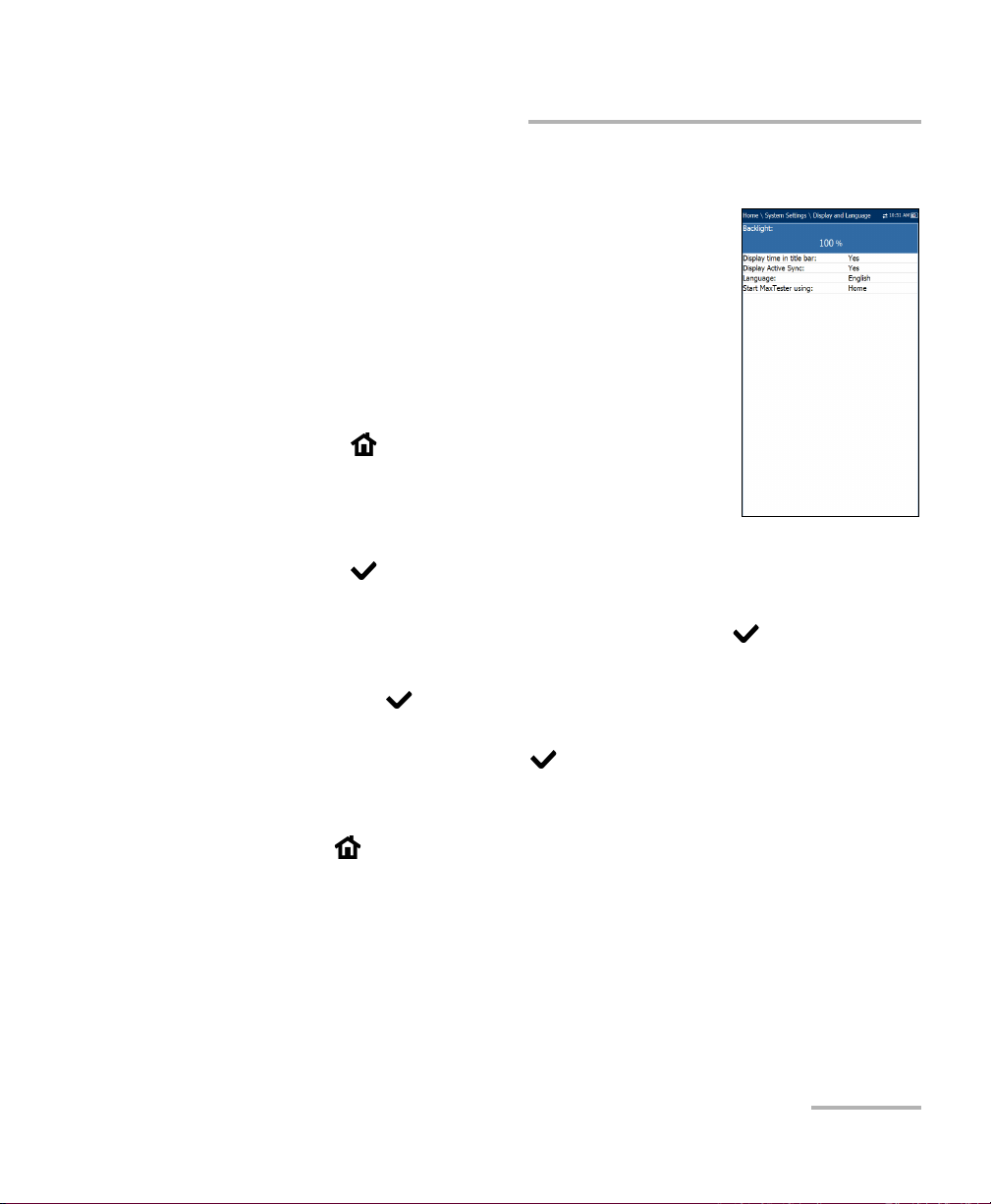
To fit your work environment, you may adjust the LCD
brightness, display the time and Active Sync, and
change the display language. The values are kept in
memory when you turn the unit off.
Note: The LCD Backlight consumes battery power; more
brightness, more power consumption.
To adjust the display settings:
1. From , select System Settings, and then
Display and Language.
2. Use the up/down arrow keys to select the setting
to change.
3. Press to select it.
By using the up/down arrow keys, you can switch between preset
brightness levels in the Backlight item. Press to confirm.
Display and Language
To display the time and Active Sync in the title bar, enable the item.
Press after your selection to confirm.
Use the up/down arrow keys to navigate between the available
languages, then press to select it. You will be prompted to
restart your unit.
To se t whic h Home page the unit defaults to when pressing
,highlight Start MaxTester using: and select from the list.
VDSL2/ADSL2+ Multi-play Test Set 17
Page 24
Setting Up the MAX-630
Date and Time
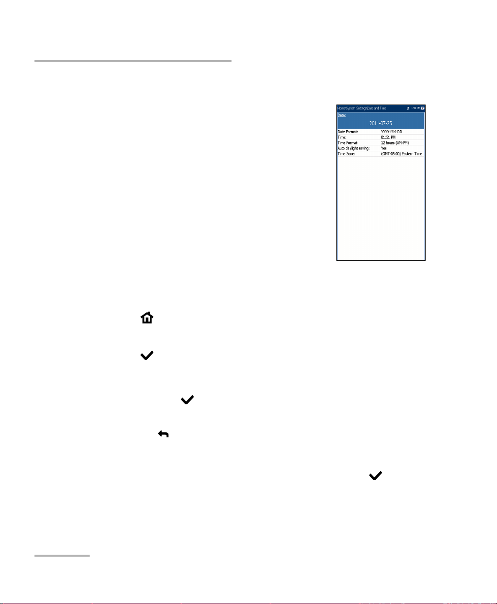
Date and Time
When saving results, the unit also saves the
corresponding Date and Time.
You can enter the date according to the following
formats:
yyyy-mm-dd
dd-mm-yyyy
mm-dd-yyyy
The time can be set according to the 12- or 24-hour
formats.
You can also modify the time zone and enable an
option so that your unit automatically adjusts the time for the daylight
saving period.
To set the date and time:
1. Press , select System Settings, and then Date and Time.
2. Use the arrows to select any of the date or time settings.
3. Press to enable the modification controls.
For the date and time, an edit screen is displayed with descriptive
function keys. Use the arrow keys to modify the number values,
then press to confirm the change and go back to the previous
screen.
Press to go back to the previous screen without saving the new
value.
For the time format, auto daylight saving and time zone values, use
the arrow keys to select the desired value, then press to
confirm the change.
18 MAX-630
Page 25
Setting Up the MAX-630
Power
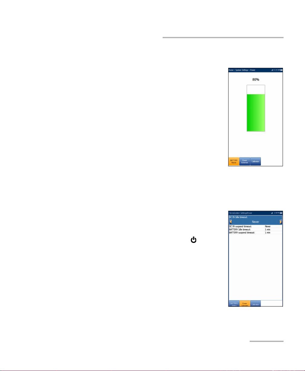
Battery Status
The BATTERY Status pane indicates the current
power level for the battery.
Note: The battery level might not display after a system
upgrade but will become available again after the
next full charge.
Power Schemes
You can set your unit to automatically switch to suspend mode
independently for the battery or DC power modes. This is useful for
example if you want to save battery power but do not want to be hindered
by unwanted switches between modes when using DC power.
Pow er
Power off completely shuts down the unit’s
power.
Power suspend puts the unit in sleep mode; you
can wake up the system by pressing .
DC IN/BATTERY Idle timeout allows you to set
the time duration for the unit to idle (no keys
pressed or test being run) before turning off the
LCD.
DC IN/BATTERY suspend timeout allows you to
set the time duration for the unit to enter sleep
mode.
VDSL2/ADSL2+ Multi-play Test Set 19
Page 26
Setting Up the MAX-630
Pow er
Note: Setting the DC IN suspend timeout to the lowest value and not to Never
ensures the unit enters suspend mode while the charger is connected.
Battery charging time is quickest when the unit is in suspend mode.
Default Power Scheme settings are:
LCD backlight turns off after system idles (no keys pressed) for
10 minutes.
Unit switches to suspend mode after timeout: 10 min
To change the power scheme settings:
1. Press , select System Settings, and then Power.
2. Select the Power Schemes tab.
3. Under DC IN or BATTERY, use the arrow keys to select Idle/suspend
timeout modes. Press to view the list of available choices or use
the left/right arrow keys.
4. Select a new value, then press to confirm the choice. Repeat for
the other modes as needed.
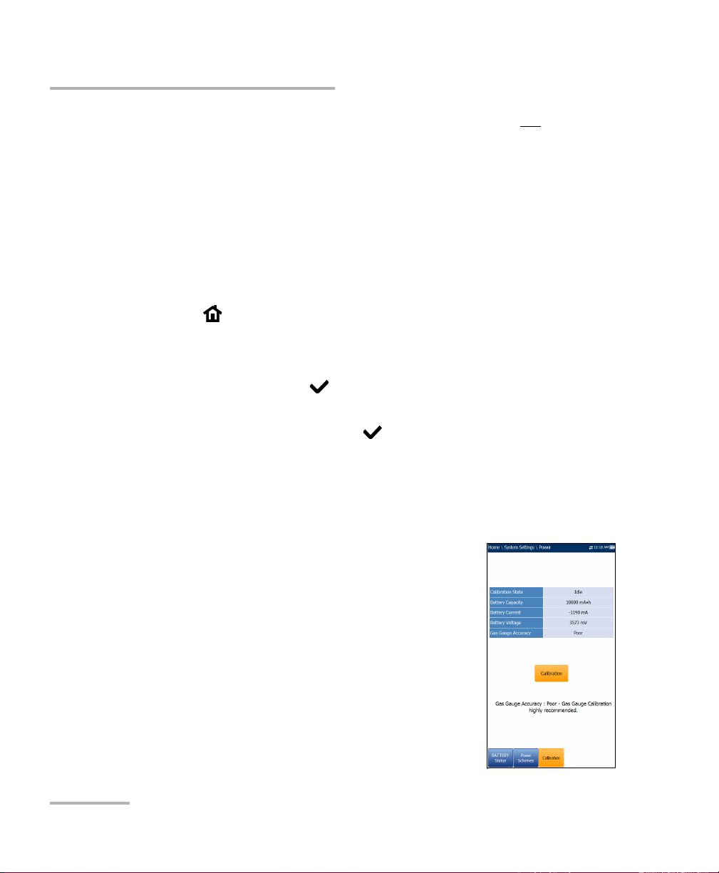
Calibration
The Calibration tab allows you to optimize the battery gas gauge accuracy.
Calibration State:
Completed displays after the calibration
procedure has been started and the DC plug
was not removed before the end was
reached.
In Progress displays when the calibration
procedure has been started but has not yet
reached the end.
20 MAX-630
Page 27

Setting Up the MAX-630
Pow er
Aborted displays when the calibration procedure has been started
but the DC plug was removed before the end.
Idle displays after the next MaxTester cold boot.
Gas Gauge Accuracy indicates the estimated battery gas gauge
accuracy.
Below 10 % accuracy error is Very Good.
Between 10 % and 20 % accuracy error is Good.
Over 20 % accuracy error is Poor and a gas gauge calibration is
needed in order to get optimal accuracy.
The following on-screen messages may appear:
Calibration Completed is displayed after the procedure has been
started and successfully completed.
Calibration In Progress is displayed when the procedure has been
started and not yet completed.
Calibration Aborted is displayed when the procedure has been
started but the DC plug was removed or a power failure occurred
before the end, or if you terminate the calibration.
To start the gas gauge calibration:
1. Select the Calibration button. Completion time is up to 20 hours
depending on the MaxTester's initial battery level and current power
consumption.
2. Make sure the DC plug always stays connected and the unit is not
turned off until completion. Failing to do so will abort the procedure
and previous calibration parameters will be kept.
Note: No other activity can be performed on the unit during calibration.
Note: Going through this calibration does not affect the MaxTester's battery
capacity.
VDSL2/ADSL2+ Multi-play Test Set 21
Page 28
Setting Up the MAX-630
Software Options
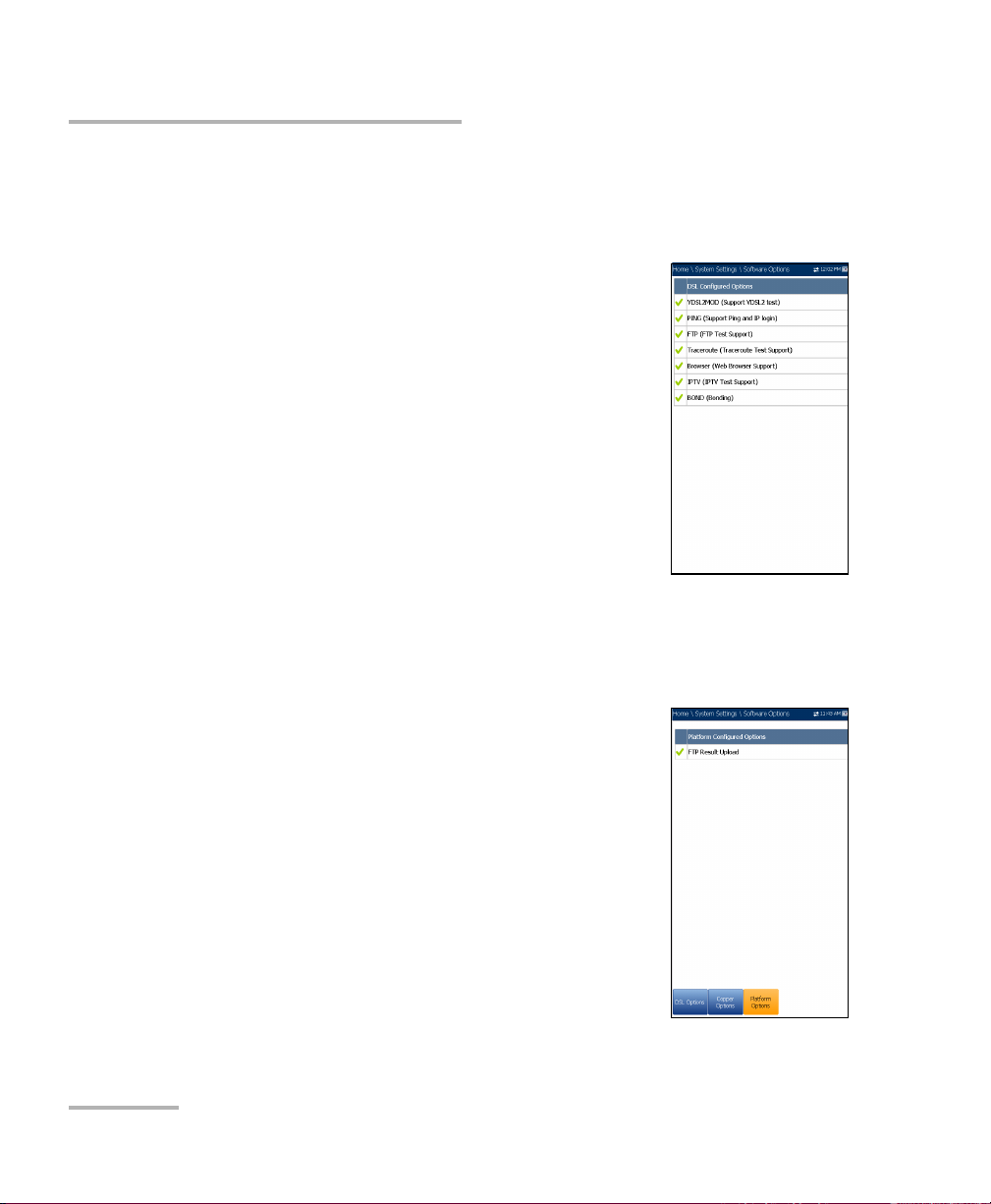
Software Options
DSL Options
This screen lists all the DSL Configured Options
which are present on the unit. Possible options are as
follow:
VDSL2MOD (Support VDSL2 test)
PING (Support Ping and IP login)
FTP (FTP Test Support)
Traceroute (Traceroute Test Support)
Browser (Web Browser Support)
IPTV (IPTV Test Support)
VOIP (VoIP Test Support)
MOS (MOS / R-Factor Scores)
Platform Options
This screen lists all the Platform Configured Options
which are present on the unit. A possible option is:
FTP Result Upload.
22 MAX-630
Page 29
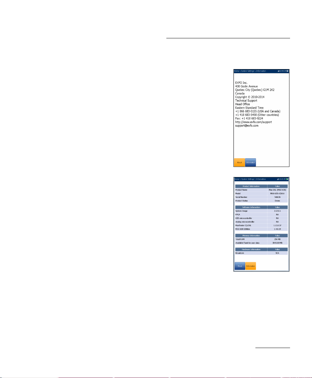
Information
About EXFO
The About tab contains contact information should
you require technical assistance.
MAX-630 Information
The Information tab displays information about the
product, software, and memory installed on the
device. The page also identifies hardware
information.
Setting Up the MAX-630
Information
VDSL2/ADSL2+ Multi-play Test Set 23
Page 30
Setting Up the MAX-630
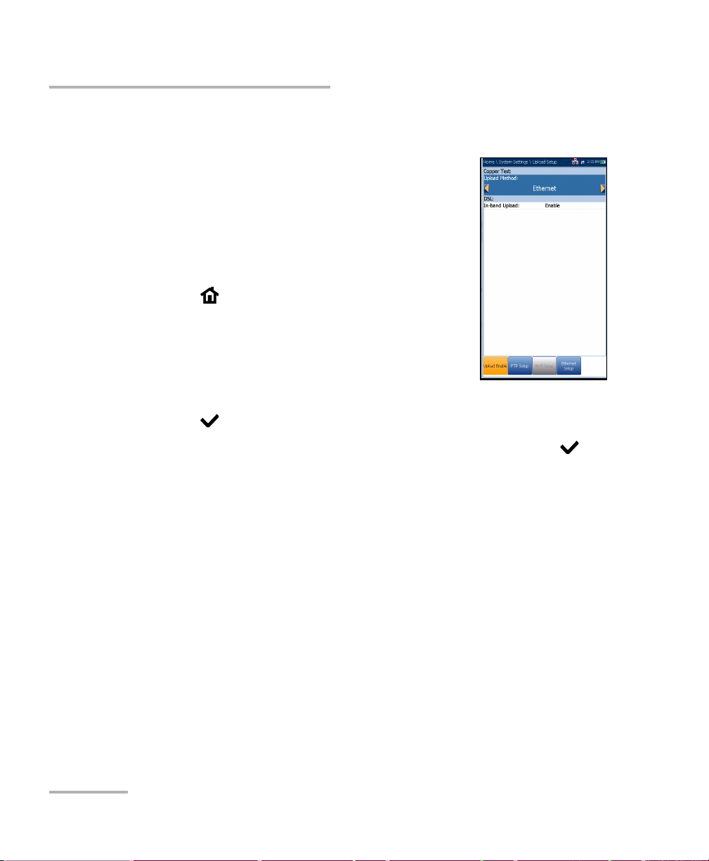
Upload Setup
Upload Setup
Upload Enable
The Upload Enable function allows you to upload
your test result files.
For DSL tests, the In-band Upload can be set to either
Enable or Disable.
To select the Upload Method:
1. Press , select System Settings, and then
Upload Setup.
2. Select the Upload Enable tab.
3. Use the left/right arrow keys.
OR
4. Press to view the list of available choices.
5. Use the up/down arrow keys to make your selection and press to
confirm.
24 MAX-630
Page 31

Setting Up the MAX-630
Upload Setup
FTP Setup
The FTP Setup function allows you to configure the
file transfer information using the following
parameters:
Address Format allows you to select the FTP
server address type:
IP Address
URL
FTP Server Address allows you to set either the
IP Address or URL.
Port is a fixed numeric value for the signalling port
used to establish an IP network session.
Username/Password is your login ID and password.
Mode is either Active or Passive for the file transfer mode.
Transfer Type is set to Binary, transferring files as a binary stream of
data.
Remote Directory can be used to specify the file upload directory on
the FTP server, for example, dir1/dir2. If this field is left empty, the FTP
upload will save the result file at root directory on FTP server.
Restore Default button allows you to reset the entries to the default
settings.
VDSL2/ADSL2+ Multi-play Test Set 25
Page 32

Setting Up the MAX-630
Upload Setup
To configure the setup options:
1. Press the up/down arrows to select the desired parameter.
2. Press the left/right arrow keys to view and select the options.
OR
3. Press on a value to open a list box of options or the alphanumeric
editor screen and use the navigation keys to scroll through.
4. Press to confirm the value.
Wi-Fi Setup
The Wi-Fi Setup pages allows you to connect your
MaxTester to a Wi-Fi network.
Select a Wi-Fi Network for Upload lists the
available secure Wi-Fi networks in range and
presently connected. (Unsecured Wi-Fi networks
are not supported.) The last three networks that
were connected are also listed, whether or not
they are presently connected to the MaxTester.
Note: If you select a network from the list of previously
selected networks (last 3), the MaxTester will try to
join that network using the credentials saved for the
selected network.
Status displays a Wi-Fi symbol if the device is connected, and is
dynamically updated with the present connectivity state of the
networks.
Network Name is the Wi-Fi network name.
A third, right-hand column displays a checkmark indicating the
network selected for upload.
Forget Network button removes a previously joined network from the
list.
26 MAX-630
Page 33

Setting Up the MAX-630
Upload Setup
Select Other Network button opens a new page allowing you to
search for a specific network.
Find Networks button searches for available networks.
To connect your MaxTester to a Wi-Fi network:
1. Press the down arrow key to highlight the list box and press to get
into the list.
2. In the list, press the up/down arrows to select the desired network.
3. Press to confirm a network and open the alphanumeric editor
screen to enter your Password.
4. Press
to come out of the list.
5. Press the down and left/right arrow keys to highlight the network
buttons and press .
VDSL2/ADSL2+ Multi-play Test Set 27
Page 34

Setting Up the MAX-630
Upload Setup
Select Network
The Select Network page allows you to search for a
specific Wi-Fi network.
Network Name opens the alphanumeric editor
screen allowing you to enter the name of the
desired Wi-Fi network.
Security lists the following wireless security
protocols:
WEP (Wired Equivalent Privacy)
WPA (Wi-Fi Protected Access)
WPA2 (Wi-Fi Protected Access version 2)
Note: When using WPA encryption, some specific routers may have performance
issues with the supplied Wi-Fi dongle. In this case, please use WPA2
encryption.
Password opens the alphanumeric editor screen allowing you to enter
the desired Wi-Fi network’s password. Join function key replaces Done
on the editor screen.
Join function key allows your MaxTester to connect to the other
network and it becomes the selected/preferred upload network.
To configure the other network parameters:
1. Press the up/down arrow keys to highlight the desired parameter.
2. Press the left/right arrow keys to view and select the options.
OR
3. Press on a value to open a list box of options or the alphanumeric
editor screen and use the navigation keys to scroll through.
4. Press to confirm the value.
5. Press the Join function key to connect to the other Wi-Fi network.
28 MAX-630
Page 35

Setting Up the MAX-630
Upload Setup
Ethernet Setup
The Ethernet Setup function allows you to configure
the line and access modes, etc for an Ethernet
connection, using the following parameters:
Access Mode options are DHCP, Static, or PPPoE.
WAN Link Speed is a choice between Auto
(negotiated during the link establishment), 100 or
10 Mbit/s.
WAN Connect Mode is Full- or Half-Duplex,
when Link Speed is set to either 100 or 10 Mbit/s.
VLAN Support enables the unit to tag/untag
ethernet frames.
VLAN ID is a virtual local area network (VLAN) tag ranging from 0
through 4094. The entry is available only when VLAN Support is
Enable.
Vendor ID is the name of the unit. This entry is available only when
Access Mode is DHCP.
Local Mac Address is the internal MAC address of the unit: either
MaxTester or User Defined.
Mac Address is a specific MAC address, in a hexadecimal format, if
User Defined was selected for the previous parameter. This entry is
available only when Access Mode is DHCP or Static.
The following parameters are available only when Access Mode is PPPoE.
Login Name/Password is your user ID and password.
Obtain IP is either Dynamic where the access concentrator or
broadband remote access server assigns a temporary IP address to
the unit, or Static where you enter the IP address of the unit.
WAN Login Timeout is a numeric setup entry.
VDSL2/ADSL2+ Multi-play Test Set 29
Page 36

Setting Up the MAX-630
Upload Setup
The following parameters are available only when Access Mode is Static.
IP Address is the address for the unit that is actively connected to
your network or the internet at the time of login.
Gateway is the IP address of the default gateway.
Subnet Mask is the network address used to identify if the IP
address is within the same wide area network.
DNS1 is the address of the primary domain name server to be used
by the unit. If DNS is unavailable, enter 0.0.0.0.
DNS2 is the address of the secondary domain name server to be
used by the unit. If DNS is unavailable, enter 0.0.0.0.
Restore Default button allows you to reset the entries to the default
settings.
To configure the setup options:
1. Press the up/down arrows to select the desired parameter.
2. Press the left/right arrow keys to view and select the options.
OR
3. Press on a value to open a list box of options or the alphanumeric
editor screen and use the navigation keys to scroll through.
4. Press to confirm the value.
30 MAX-630
Page 37

5 Setting Up DSL/IP Tests
DSL Main Menu Page
DSL Main presents the main menu page which allows
you to navigate to each icon using the up/down
left/right arrow keys on the keypad. Press to bring
up the sub-menu of the selected icon:
For Auto, Manual, or Ethernet, the test will start
and the screen control will navigate to the Result
Summary page.
Read/Export Result opens a list of file names
previously saved tests, to view or export results.
Test Configuration provides the utilities to
configure test parameters.
Setup opens a sub-menu displaying the following:
Modem Settings allows you to set the display and power
parameters of the modem.
Application Settings allows you to preset the unit with specific
DSL measurement values.
VDSL2/ADSL2+ Multi-play Test Set 31
Page 38

Setting Up DSL/IP Tests
Test Configuration
Test Configuration
The MaxTester supports 3 types of test applications: Auto Test, Manual
Test , and Ethernet Test. Configuration parameters for all 3 test applications
are saved into a test configuration profile. A default profile is provided with
a predefined set of parameters for all test applications.
Select Profile lists saved available profiles. The
current active profile is shown in the upper
information header. At power up, settings are read
from the last loaded profile.
Profile Details lists the 3 types of tests for
configuration:
Auto Test Setup
Manual Test Setup
Ethernet Test Setup
Copy to USB allows you to copy all profiles found
in the internal memory to an external USB device.
If the profile name already exists in the destination folder, Copy (x) will
be appended to the profile name, where x corresponds to the number
of copies starting from 1.
Copy from USB allows you to copy all profiles found on an external
USB device to the unit.
Delete Profile allows you to delete a profile (except the default profile)
on the unit.
Profile Default resets the current test setup to the factory default
profile. If selected, a dialogue box pops up to confirm that all single
and auto test settings will revert to factory test settings.
Save Profile opens the alphanumeric editor screen allowing you to
create a new profile name and copy all parameters from the currently
loaded profile.
32 MAX-630
Page 39
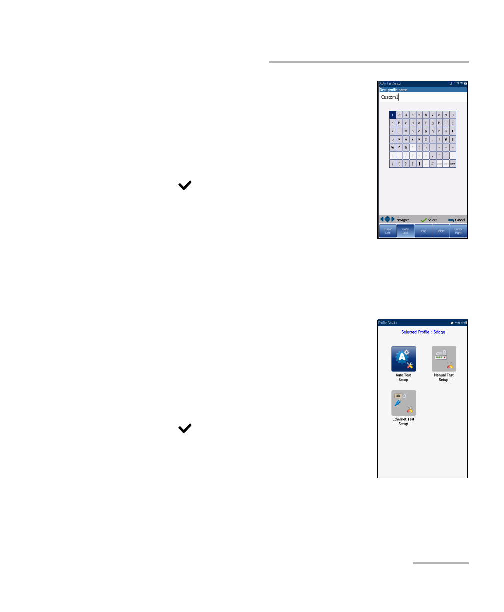
Setting Up DSL/IP Tests
Setup Profile Name
This alphanumeric editor screen allows you to change
parameter values and save changes to a new name.
To use the editor screen:
1. Press the up/down left/right arrows to navigate the
on-screen keyboard.
2. Press to confirm each selection.
3. Use the on-screen function buttons to create or
edit the name.
Profile Details Menu
You can view any of your saved profiles on the
MaxTester from the Profile Details menu by selecting
the desired test setup icon. This sub-menu displays an
icon for each test: Auto Test, Manual, and Ethernet.
Test Configuration
To select a test:
1. Press the up/down left/right navigation keys to
select the desired icon.
2. Press to display the test profile details.
VDSL2/ADSL2+ Multi-play Test Set 33
Page 40

Setting Up DSL/IP Tests
Test Configuration
Connection Setup
The Connection Setup tab allows you to configure the
line and access modes, etc of your test dependent on
your unit’s Software Options and model
Information.
The A2XAA or V2XAA unit does Annex A and Bonding.
Annex A is on pair 1 and bonding uses pair 1 and
pair 2.
The Test I nt erfa c e setup options for A2XAA or
V2XAA modules are the following:
ADSL2+ - if VDSL2 option disabled.
VDSL2/ADSL2+ - if VDSL2 option enabled
ADSLMulti supports G.DMT, T1.413, and G.Lite.
ADSL2+ Bonding - if VDSL2 option disabled, Bonding option
enabled.
VDSL2/ADSL2+ Bonding - if VDSL2 and Bonding options enabled.
VDSL2-30a - if VDSL2 option enabled.
The VA2XAB unit does Annex A and Annex B. Annex A is on pair 2 and
Annex B is on pair 1.
The Test I nt erfa c e setup options for the VA2XAB module are the
following:
ADSL2+ (xB/P1) - if VDSL2 option disabled, Annex B mode.
ADSL2+ (xA/P2) - if VDSL2 option disabled, Annex A mode.
VDSL2/ADSL2+ (xB/P1) - if VDSL2 option enabled, Annex B mode.
VDSL2/ADSL2+ (xA/P2) - if VDSL2 option enabled, Annex A mode.
ADSLMulti (xB/P1) - supports G.DMT only.
34 MAX-630
Page 41

Setting Up DSL/IP Tests
Test Configuration
ADSL2Multi (xA/P2) - support G.dmt and T1.413 only.
VDSL Bonding - if VDSL2 and Bonding options are enabled.
VDSL2-30a (P1) - if VDSL2 option is enabled.
Annex M allows you to Enable/Disable this option when Test
Interface is ADSL2+ (xA/P2) or VDSL2/ADSL2+ (xA/P2).
Annex J allows you to Enable/Disable this option when Te s t Int e rfa c e
is ADSL2+ (xB/P1) or VDSL2/ADSL2+ (xB/P1).
ADSL Transport displays the transport type options: PTM (packet
transfer mode), ATM (asynchronous transfer mode), or ATM and PTM.
Access Mode options are dependent on the Test In terf a ce selection:
If ADSL2+, ADSLMulti, and VDSL2/ADSL2+- available options are
Sync Only, Bridged (not in Auto Test), DHCP, Static, PPPoE, PPPoA,
IPoA.
If ADSL2+ Bonding and VDSL2 Bonding - available options are
Sync Only, Bridged (not in Auto Test), DHCP, Static, PPPoE.
For Ethernet - available options are Bridged, DHCP, Static, PPPoE.
Auto Resync allows you to Enable the SyncLossCounter as the
Pass/Fail criteria. When SyncLossCounter+1 is reached, the test will
have fail status.
If Auto Resync is disabled, any time the test loses sync, the result status
will be fail and the test will stop automatically.
Sync Timeout Period enables you to enter the duration, between
2 and 30 minutes, to run a DSL test from activation to reaching
Show Time.
Keep Sync Time is either:
Continuous where the test runs until you manually stop it, or
User Defined where you can set a Keep Sync Time Period.
Default is 5 minutes.
VDSL2/ADSL2+ Multi-play Test Set 35
Page 42

Setting Up DSL/IP Tests
Test Configuration
VPI (ATM mode only) is the virtual path identifier (VPI) ranging from 0
through 255 for the downstream channel.
VCI (ATM mode only) is the virtual circuit identifier (VCI) ranging from
32 through 65535 for the downstream channel.
Encapsulation Type depends on the network configuration and sets
the ATM to either LLC also known as LLC-SNAP (logical link
control-sub network address protocol) or VC_MUX (virtual channel
multiplex).
VLAN Support enables the unit to tag/untag ethernet frames.
VLAN ID is a virtual local area network (VLAN) tag ranging from 0
through 4094. The entry is available only when VLAN Support is
Enable.
Vendor ID is the name of the unit. This entry is available only when
Access Mode is DHCP.
Local Mac Address is the internal MAC address of the unit: either
MaxTester or User Defined.
Mac Address is a specific MAC address, in a hexadecimal format, if
User Defined was selected for the previous parameter. This entry is
available only when Access Mode is DHCP or Static.
The following parameters are available only when Access Mode is PPPoE
or PPPoA.
Login Name is your user ID.
Password is your password.
Obtain IP is either Dynamic where the access concentrator or
broadband remote access server assigns a temporary IP address to
the unit, or Static where you enter the IP address of the unit.
36 MAX-630
Page 43

Setting Up DSL/IP Tests
Test Configuration
Static IP is the address of the current location assigned by the
service provider. This entry is available only if Obtain IP is set to
Static.
WAN Login Timeout is a numeric setup entry.
The following parameters are available only when Access Mode is IPoA or
Static.
IP Address is the address for the unit that is actively connected to
your network or the internet at the time of login.
Gateway is the IP address of the default gateway.
Verif y Gateway can be set to Enable or Disable.
Subnet Mask is the network address used to identify if the IP
address is within the same wide area network.
DNS1 is the address of the primary domain name server to be used
by the unit. If DNS is unavailable, enter 0.0.0.0.
DNS2 is the address of the secondary domain name server to be
used by the unit. If DNS is unavailable, enter 0.0.0.0.
The following parameters are available only when Te s t Int e rfa ce is
Ethernet.
WAN/LAN Link Speed is a choice between Auto (negotiated
during the link establishment), 100 or 10 Mbit/s.
WAN/LAN Connect Mode is Full- or Half-Duplex, when Link
Speed is set to either 100 or 10 Mbit/s.
VDSL2/ADSL2+ Multi-play Test Set 37
Page 44

Setting Up DSL/IP Tests
Test Configuration
To configure the setup options:
1. Press the up/down arrows to select the desired parameter.
2. Press the left/right arrow keys to view and select the options.
OR
3. Press on a value to open a list box of options or the alphanumeric
editor screen and use the navigation keys to scroll through.
4. Press to confirm the value.
5. If you make any changes to the parameter values, press the on-screen
function keys to save or cancel your input.
38 MAX-630
Page 45

Setting Up DSL/IP Tests
Test Configuration
LAN Setup
The LAN Setup tab is available only in Manual Test
Setup and when the Access Mode set in Connection
Setup is not Sync Only. LAN Setup allows you to
configure the parameters required when working in
Pass Through Mode, and the LAN (local area
network) is connected to the external device which
supports 10/100 Ethernet.
This tab is not available in Auto Test Setup.
Pass Through Mode - Enable or Disable.
LAN IP Address is the local network IP address of
the unit.
Note: If the DSL WAN has an IP address on a specific subnet (for example
192.168.x.y) and the Ethernet LAN port is enabled, configure the default
LAN IP address to a different subnet (for example 10.0.x.y) to avoid IP
communication problems.
Subnet Mask is the network address mask used to identify if the IP
address is within the same local area network.
DHCP Server enables the dynamic host configuration protocol (DHCP)
mode for the LAN side of the connection.
Platform Ip Address displays the IP address of the unit’s platform
when the DHCP Server is disabled.
To configure LAN setup values:
1. Press the up/down arrows to select the desired parameter.
2. Press the left/right arrow keys to view and select the options.
OR
3. Press on a value to open a list box of options or the alphanumeric
editor screen and use the navigation keys to scroll through.
VDSL2/ADSL2+ Multi-play Test Set 39
Page 46

Setting Up DSL/IP Tests
Test Configuration
4. Press to confirm the value.
5. If you make any changes to the parameter values, press the on-screen
function keys to save or cancel your input.
Thresholds
The Thresholds tab allows you to define DSL
parameter criteria. For D/S (downstream) and U/S
(upstream) data rates, there are OK and Min
(minimum) bit rates defined to indicate unacceptable,
marginal, and acceptable rates.
D/S and U/S OK bit rate:
for ADSL - value limited to D/S 30 Mbit/s,
U/S 2 Mbit/s.
for VDSL - D/S to 100 Mbit/s, U/S to 50 MBit/s.
D/S and U/S Min SNR margin - values range from
0 to 63.5 dB. Default is 5 dB.
D/S and U/S Max Attenuation - values range from 0 to 96 dB. Default is
10 dB.
Sync Loss Counter is the number of times the unit lost
synchronization.
To set threshold values:
1. Press the up/down arrows to select the desired parameter.
2. Press the left/right arrow keys to view and select the options.
OR
3. Press on a value to open the alphanumeric editor screen and use
the navigation keys to scroll through.
40 MAX-630
Page 47

Setting Up DSL/IP Tests
Test Configuration
4. Press to confirm the value.
5. If you make any changes to the parameter values, press the on-screen
function keys to save or cancel your input.
Select Tests
The Select Tests page allows you to Enable/Disable
the following optional sub-tests, within the 3 types of
test applications.
VoIP Test determines DSL and IP packet rates,
and calculates jitter, packet loss, and packet delay.
When enabled, all other sub-tests are
automatically disabled.
IPTV Test supports STB (set-top box) emulation
mode over DSL and Ethernet interfaces enabling
the MaxTester to join and leave multicast IPTV
streams. When enabled, all other sub-tests are
automatically disabled.
Ping is also known as ICMP echo request and determines network
connectivity and accessibility.
FTP test verifies the file transfer speed of the file download and upload.
Traceroute is a complement tool of the Ping test to determine why a
destination cannot be reached, or where the internet is broken.
Web Browser Test can only be started when a WAN connection
(either through xDSL or Ethernet) has been established.
When enabled, the sub-tests’ test pages are available in the results pages.
When highlighted, the sub-tests’ setup contents are shown on the Tes t
Setup tab.
Note: Select Tests and Te st S et up tabs are not available in Sync Only and
Bridged Access Modes.
VDSL2/ADSL2+ Multi-play Test Set 41
Page 48

Setting Up DSL/IP Tests
Test Configuration
To select sub-tests:
1. Press the up/down arrows to highlight the desired test. VoIP/IPTV Test
must be disabled to view all other sub-tests.
2. Press the left/right arrow keys to toggle between Enable/Disable.
OR
3. Press on any value to open the list box to toggle between
Enable/Disable.
42 MAX-630
Page 49

Setting Up DSL/IP Tests
Test Setup
The Test S et up tab allows you to configure profile values for the optional
sub-tests within the 3 types of test applications. You must highlight the
sub-test on the Select Tests page in order to display the sub-test’s
parameters on the Test S etup page.
VoIP Test Setup
The VoIP test function allows you to configure the unit
for VoIP testing. During the analysis, the unit
determines the DSL and IP packet rate, and calculates
jitter, packet loss, and latency.
Codec is the VoIP coder/decoder value to be used
by the unit.
Call Mode (enabled for Auto Test only) is either
Incoming or Outgoing. The VoIP test is not only
used to initiate a VoIP call, but responds to
incoming VoIP calls.
Test Setup
Note: When Incoming mode is selected, Auto Answer is set
to Yes , and is read only. When Outgoing mode is selected, Auto Answer is
set to No, and is read only; that is, incoming calls are rejected.
Auto Answer (disabled for Auto Test) is either Ye s or No. When an
incoming call is detected, a popup message will indicate that this state
is detected with the message Incoming call.
If Auto Answer is No, then the popup presents you with the
choices: Answer or Decline.
If Auto Answer is Yes, then the popup message presented is
Incoming call, and persists for 5 seconds.
Test D urat i on allows you to set the duration of the VoIP test, in
seconds.
VDSL2/ADSL2+ Multi-play Test Set 43
Page 50

Setting Up DSL/IP Tests
Test S e t u p
Communication Channel is the parameter based on either UDP or
TCP.
Controller Setup button opens a new page that allows you to set the
required VoIP parameters for the unit.
Proxy Setup button opens a new page that allows you to set
parameters for the Proxy.
To configure test setup values:
1. Press the up/down arrow keys to select the desired parameter.
2. Press the left/right arrow keys to view and select the options.
OR
3. Press on a value to open a list box of options or the alphanumeric
editor screen and use the navigation keys to scroll through.
4. Press to confirm the value.
5. If you make any changes to the parameter values, press the on-screen
function keys to save or cancel your input.
Controller Setup
The Controller is the local VoIP connection for your
MaxTester. The Controller Setup Info page allows
you to set the following VoIP parameters for your unit:
User Name allows you to enter alphanumeric
characters in this field using the editor screen to
create a name.
Signalling Port (read only) displays a fixed
numeric value of the signalling port used to
establish an IP network session.
Address Format (read only) displays DNS Name.
Domain (read only) displays the domain name
www.exfo.com.
44 MAX-630
Page 51

Setting Up DSL/IP Tests
To enter a user name:
1. Press to open the alphanumeric editor screen and use the
navigation keys to scroll through.
2. Press to confirm the value.
Proxy Setup
Proxy is the registered /proxy sip server. The Proxy
Setup Info page allows you to set the following
required server’s VoIP p a ra me te rs :
Proxy User Name allows you to enter
alphanumeric characters in this field using the
editor screen to create a name.
Proxy Port is a numeric value of the proxy port
used to establish an IP network session.
Address Format is either IP Address or DNS
Name.
Test Setup
Proxy Domain allows you to enter either the
address of the IP or name of the domain server.
Proxy Password allows you to set a password for the proxy domain.
To setup the proxy info:
1. Press the up/down arrow keys to select the desired parameter.
2. Press the left/right arrow keys to view and select the options.
OR
3. Press on a value to open a list box of options or the alphanumeric
editor screen and use the navigation keys to scroll through.
4. Press to confirm the value.
VDSL2/ADSL2+ Multi-play Test Set 45
Page 52

Setting Up DSL/IP Tests
Test S e t u p
IPTV Test Setup
IPTV test supports STB (set-top box) emulation mode
over xDSL and Ethernet interfaces enabling the
MaxTester to join and leave multicast IPTV streams.
The following parameters can be configured from the
Test S etup tab:
Display Mode is either the Channel Name or #
used for displaying channel information in the
result pages.
IGMP Version is a value of either 2 or 3 used to
send IGMP join/leave messages.
Note: If you change the IGMP Version from the default of 2
to 3, you must reboot your unit.
Max TS Packet Loss Ratio is an editable percentage, ranging from 1 to
50, used to qualify if the IPTV stream is stable.
Max ZAP Time is an editable value ranging from 0 to 10,000 that
measures the channel switch time in ms.
Channel List Setup button accesses the page to configure parameters
for channel analysis.
Auto IPTV Test Setup button accesses the setup page to automatically
run an IPTV test. This function is only available in Auto Test Setup
application.
46 MAX-630
Page 53

Setting Up DSL/IP Tests
Test Setup
To configure test setup values:
1. Press the up/down arrow keys to select the desired parameter.
2. Press the left/right arrow keys to view and select the options.
OR
3. Press on a value to open a list box of options or the alphanumeric
editor screen and use the navigation keys to scroll through.
4. Press to confirm the value.
5. If you make any changes to the parameter values, press the on-screen
function keys to save or cancel your input.
Channel List Setup
The Channel List Setup page in the IPTV test setup
provides a tool for you to create an alias table. It
allows you to join/leave an IPTV stream using a
symbolic name or TV channel number instead of the
IP address. Maximum entries in the table are 100,
divided into pages.
Channel Info lists 3 editable parameters:
Channel # is a numeric value from 1 to 9999.
Channel Name is a 24-character
alphanumeric entry.
IP Address is a multicast address from
224.1.1.1 to 239.255.255.254.
Previous/Next Entry buttons highlight the previous/next entry in the
table (up/down direction). When the highlight reaches the first/last
entry of the alias table page, the button(s) is disabled.
VDSL2/ADSL2+ Multi-play Test Set 47
Page 54

Setting Up DSL/IP Tests
Test S e t u p
On-screen function buttons:
Add/Insert adds currently edited channel info into the alias table
below the highlighted entry and moves the highlight to the newly
added entry. If the page is full, the bottom entry moves to the next
page. Selecting the highlight placement allows you add and group
entries with similar parameters.
Delete removes the highlighted entry in the alias table. If the
deleted entry was also present in the IPTV Channel Analysis list or
Join/leave Test list in Auto IPTV Test Setup page, it will also be
removed from those lists.
Accept replaces the edited value for the current highlighted entry.
Use this function for modification purposes.
Page Up/Down display the previous/next page(s) of the alias table.
If current page is the first/last page, the button(s) are disabled.
To setup the channel list:
1. Press the up/down, right/left keys to select the desired channel
parameter.
2. Use the on-screen function buttons to create or edit the channel list.
OR
3. Use the navigation keys to select the Previous/Next Entry button(s)
and press to select the entry to be highlighted and edited.
48 MAX-630
Page 55

Setting Up DSL/IP Tests
Auto IPTV Test Setup
The Auto IPTV Test Setup page in the IPTV test
setup allows you to define 2 types of IPTV tests to run
automatically:
Join/leave Test - Enable to define a list of
channels to sequentially join and leave. If
disabled, no test is performed.
Channel 1-10 allows you to define a list of
up to 10 channels.
IPTV Channel Analysis - Enable to add
channels for analysis. If disabled, channel
analysis in auto test is not performed.
Stream Time defines the length of time, from 1 to 60 s, to keep the
channel stream(s) for analysis.
Channel 1-5 allows you to define up to 5 IPTV channels for
concurrent analysis.
Test Setup
On-screen function buttons:
Add/Insert is available only when a blank entry is highlighted.
When the button is pressed, the first available channel from the
alias Channel List is automatically added to this list of channels.
Upon highlighting another blank entry, the next channel from the
alias table is added, and so on.
Delete removes the selected channel from the list.
You can Enable either one or both, but you cannot Disable both of them at
same time. If both tests are enabled, Join/leave Test runs first.
VDSL2/ADSL2+ Multi-play Test Set 49
Page 56

Setting Up DSL/IP Tests
Test S e t u p
To configure test setup values:
1. Press the up/down arrow keys to select the desired parameter.
2. Press the left/right arrow keys to view and select the options.
OR
3. Press on a value to open a list box of options or the alphanumeric
editor screen and use the navigation keys to scroll through.
4. Press to confirm the value.
50 MAX-630
Page 57

Setting Up DSL/IP Tests
Ping Test Setup
The Test S et up tab is available only if Access Mode is
not Sync Only.
Address Format is URL, IP Address, or Gateway.
URL/IP Address lists either the URL or IP Address
where the unit pings.
Packet Size is a value from 32 through 1200 of the
number of bytes sent in one packet. The default
value is 32.
Total Pings is the total number of Ping packets to
send out from1 through 99. The default value is 3.
Timeout is the time in seconds from 1 through 10,
that the unit will wait for a response back from the destination device.
To configure test setup values:
1. Press the up/down arrow keys to select the desired parameter.
Test Setup
2. Press the left/right arrow keys to view and select the options.
OR
3. Press on a value to open a list box of options or the alphanumeric
editor screen and use the navigation keys to scroll through.
4. Press to confirm the value.
5. If you make any changes to the parameter values, press the on-screen
function keys to save or cancel your input.
VDSL2/ADSL2+ Multi-play Test Set 51
Page 58

Setting Up DSL/IP Tests
Test S e t u p
FTP Test Setup
The FTP test verifies the file transfer speed of the file
download and upload. The FTP Test S et up tab allows
you to configure the following parameters:
Address Format is URL or IP Address.
FTP Server Address lists either the URL or IP
Address.
Login Name/Password is your user ID and
password.
Download File Name is the filename requested
for downloading, maximum 128 characters.
Upload File Name is the filename used for
uploading, maximum 128 characters.
Upload File Size (kB) is the number of bytes or size of the file to be
uploaded to the server.
File Upload/Download - Enable/Disable options available only in
Auto Test Setup. Enable to perform the upload/download operation
automatically.
To configure test setup values:
1. Press the up/down arrow keys to select the desired parameter.
2. Press the left/right arrow keys to view and select the options.
OR
3. Press on a value to open a list box of options or the alphanumeric
editor screen and use the navigation keys to scroll through.
4. Press to confirm the value.
5. If you make any changes to the parameter values, press the on-screen
function keys to save or cancel your input.
52 MAX-630
Page 59

Setting Up DSL/IP Tests
Traceroute Test Setup
The Traceroute Tes t Setu p tab allows you the
configure the following parameters:
Address Format is URL or IP Address.
Destination Address is the destination IP or URL
address.
Max Hops specifies the maximum number of
hops (1 to 32) used in attempting to reach the
destination address.
Timeout is the time in seconds from 1 to 10, that
the unit will wait for a response back from the
destination device.
To configure test setup values:
1. Press the up/down arrow keys to select the desired parameter.
2. Press the left/right arrow keys to view and select the options.
Test Setup
OR
3. Press on a value to open a list box of options or the alphanumeric
editor screen and use the navigation keys to scroll through.
4. Press to confirm the value.
5. If you make any changes to the parameter values, press the on-screen
function keys to save or cancel your input.
VDSL2/ADSL2+ Multi-play Test Set 53
Page 60

Setting Up DSL/IP Tests
Test S e t u p
Web Browser Test Setup
The Test S et up page for the web browser content is
displayed when the Web Browser Test is highlighted
on the previous Select Tests tab. Here you can edit the
Bookmarks and Home URL.
Bookmarks lists 9 entries. The default is http://.
The Bookmarks list is shared by all 3 tests (Auto Test,
Manual, and Ethernet tests). If the list is changed in
one test, the changes are reflected in the other two.
Home URL acts as the Home URL for the web
browser test page when started. It is independent
among the 3 types of test applications.
Copy to Home URL allows you to set a highlighted URL as the Home
URL.
To configure the web browser setup:
1. Press the up/down arrows to highlight the desired entry in the list.
2. Press to access the edit screen.
3. If you make any changes to the test values, press the on-screen
function keys to save or cancel your input.
54 MAX-630
Page 61

Setup
The Setup function displays the following sub-menu:
Modem Settings allows you to set the display and
power parameters of the modem.
Application Settings allows you to preset the unit
with specific DSL measurement values.
VoIP Phone Book includes pages to setup and
save phone numbers for the VoIP test.
Modem Settings
Modem Settings provide the means to configure the
unit power scheme.
Display Modem allows you to display the modem
state in the title bar of the unit. Default value is
Yes.
Setting Up DSL/IP Tests
Setup
Modem Power OFF:
Immediately for when a DSL/IP test is
completed or stopped. In this mode, the
modem is powered on when DSL/IP test
starts.
Idle values power off the modem within a
defined period after an DSL/IP test is completed or stopped.
If your modem is V2XAB, then DSLAM entry is visible and allows you to
choose the following:
Annex B
UR2
Annex B and UR2
VDSL2/ADSL2+ Multi-play Test Set 55
Page 62

Setting Up DSL/IP Tests
Setup
To access the modem settings:
1. From , select DSL/IP Tests, Setup, and then Modem Settings.
2. Use the up/down arrow keys to select the setting to change.
3. Press to view the list of available choices or use the left/right arrow
keys.
4. Press to confirm.
56 MAX-630
Page 63

Setting Up DSL/IP Tests
Setup
Application Settings
Before executing the DSL/IP tests, the Application Settings function allows
you to set general settings and identification fields.
To access Application Settings:
From the Home pane, select DSL/IP Tests, Setup, and then
Application Settings. The following parameters are available to
configure:
General
The General tab allows you to configure the unit with
specific measurement values.
Report Format is MaxTester, HTML, MHTML, or
XML as the generated report format.
Result File Storage Location allows you to select
where to save your results: to a USB or the internal
memory of the MaxTester
Prompt To Save Results allows you to
Enable/Disable popup confirmation messages
before leaving a test and not saving results.
Show Time Beep allows you to select the time
span for a beep from 0 to 3 seconds.
To access the parameter values:
1. Press the up/down arrow keys to highlight the desired parameter.
2. Press the left/right arrow keys to view and select the options.
OR
3. Press on a value to open a list box of options.
4. Press to confirm the value.
VDSL2/ADSL2+ Multi-play Test Set 57
Page 64

Setting Up DSL/IP Tests
Setup
Identification
The Identification tab allows you to preset values to
identify each single and auto test result file when
saving them. The parameters are as follow:
User Name/User ID allow you to enter up to 25
alphanumeric characters, in each field.
Test F r om/To list the following values: DSLAM,
NID, CPE, CROSSBOX, FRAME - up to 20 entries
each, including user defined values.
Test F r om/To List Setup buttons open separate
list management pages.
To select the parameter values:
1. Press the up/down arrow keys to highlight the desired parameter.
2. Press the left/right arrow keys to view and select the options.
OR
3. Press on a value to open a list box of options or the alphanumeric
editor screen and use the navigation keys to scroll through.
4. Press to confirm the value.
58 MAX-630
Page 65
Setting Up DSL/IP Tests
Setup
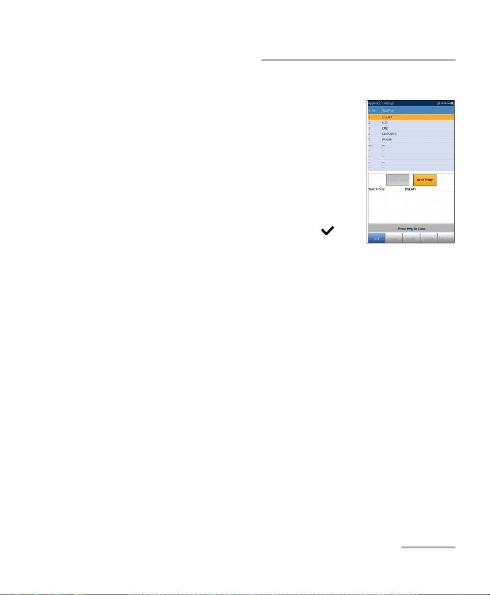
Test List Setup
The Test From List Setup and Test To List Setup
pages allow you to manage the entries of the list.
However, there are 5 entries by default which cannot
be edited or deleted. These are DSLAM, NID, CPE,
CROSSBOX, and FRAME. When any of these are
selected, the Delete and Accept buttons are disabled.
A maximum of 20 different entries can be added.
To manage the list:
1. Press the left/right arrow keys to select the
Previous/Next Entry buttons and press to
select the previous/next entry.
2. Press Page Up/Down function keys to see entries on the previous or
next pages. These keys are disabled if no other pages exist.
3. Press Add function key to add an entry just below the selected entry in
the list.
4. To edit an entry, press the up/down arrow keys to highlight the selected
test. Press Accept function key to confirm the changes. If you press
Previous/Next Entry buttons before the Accept function key, the
edited value will be lost.
5. Press Delete function key to delete any entry you have added.
VDSL2/ADSL2+ Multi-play Test Set 59
Page 66
Setting Up DSL/IP Tests
Setup
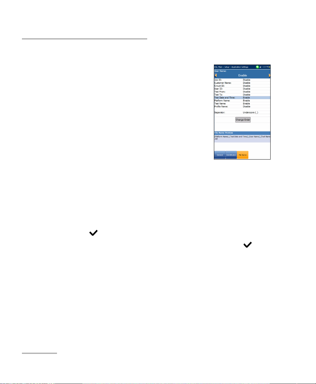
File Name
The File Name tab sets up the standard configuration
for automatically naming a result file. You can only
Enable/Disable the entries. All enabled entries are
considered for file name generation.
File Name Preview displays a preview of the file
name. The actual values of the enabled entries
are not shown.
Date and Time value format depends on the
format selected in System Settings. This entry
cannot be disabled.
Separator allows you to choose a value to
separate the enabled entries in the file name, e.g.: Space ( ), Dash (-),
Underscore (_).
To select an entry and choose a value:
1. Press the up/down arrow keys to highlight the desired entry.
2. Press the left/right arrow keys to view and select the options.
OR
3. Press on a value to open a list box of options.
4. Press the up/down arrow keys to select the option and press to
confirm your selection.
60 MAX-630
Page 67

Setting Up DSL/IP Tests
Setup
Change Order
Change Order page allows you to change the order of
the entries in the file name.
To change the order:
1. Press to get into the list.
2. Use the up/down arrow keys to select the desired
entry.
3. Press to come out of the list.
4. Press the up or down arrow key to activate the
Up/Down buttons.
5. Using the left/right arrow keys, select Up/Down and press to move
the entry up/down the list.
6. Press to go back to the File Name tab. The File Name Preview will
be updated with your changes.
VDSL2/ADSL2+ Multi-play Test Set 61
Page 68

Setting Up DSL/IP Tests
Setup
VoIP Phone Book
The Phone Book menu presents a selection of
functions which allow you to manage phone numbers
relevant to performing VoIP tests.
The functions are as follow:
Phone Book Details displays an editable list of
phone book entries.
Load Phone Book allows you to import a phone
book from either the internal memory of a USB.
Save Phone Book allows you to save or export a
phone book.
Delete Phone Book allows you to delete an entry.
To navigate between the phone book functions:
1. Press the up/down left/right arrow keys on the keypad to select an
icon.
2. Press
62 MAX-630
to confirm your selection.
Page 69

Setting Up DSL/IP Tests
Phone Book Details
The Phone Book Details page allows you to view,
add, and edit VoIP Phone Book entries.
Selected Entry is the current SIP Address entry
that you selected.
Entry displays the entry number and cannot be
edited.
SIP Address has the form username@host,
where username is the SIP user name (or
number) and host is the SIP server IP address or
domain name.Examples of SIP Address are:
john@206.162.164.122
3145551212@domain.com
john@206.162.164.122:5060
On-screen function buttons:
Setup
Add/Insert adds a new entry into the Phone Book below the
highlighted entry and moves the highlight to the newly added one. If
the page is full, the bottom entry moves to the next page.
Delete removes the highlighted entry in the Phone Book.
Modify replaces the edited value of the current highlighted entry.
Page Up/Down display the previous/next page(s) of the Phone Book. If
current page is the first/last page, the button(s) are disabled.
To setup the Phone Book details:
1. Press the up/down arrow keys to select the desired entry.
2. Use the on-screen function buttons to create or edit the details.
VDSL2/ADSL2+ Multi-play Test Set 63
Page 70

Setting Up DSL/IP Tests
Setup
Enter SIP Address
The alphanumeric editor screen allows you to add
and change parameter values, and save changes to
the Phone Book.
To use the editor screen:
1. Press the up/down left/right arrows to navigate the
on-screen keyboard.
2. Press
to confirm each selection.
3. Use the on-screen function buttons to create or
edit the address.
Load Phone Book
The Load Phone Book page allows you to import a
phone book. The page lists phone book files stored at
a particular location and displays the Loaded File
name and date of the last phone book loaded.
Only .csv files are supported.
The Storage Location lists the load destinations:
MT internal memory
USB
Entry displays the entry number of the phone
book(s).
File Name lists the phone book file name(s) to load.
Load button imports the selected phone book. You will be prompted
for confirmation since this action will overwrite the current phone
book.
64 MAX-630
Page 71

Setting Up DSL/IP Tests
To load a phone book:
1. Select the Storage Location using the left/right arrow keys.
OR
Setup
2. Press
to display the list of options.
3. Using the up/down arrow keys, select a file name to load.
4. Press Load button and confirm. The unit will remove the existing
phone book and replace it by the loaded one.
Save Phone Book
The Save Phone Book page allows you to save or
export a phone book.
Save File allows you to enter a file name of the
current phone book to save. By default, the name
is phone_book.csv.
The Storage Location lists the save destinations:
MT internal memory
USB
Save button saves the selected file.
Note: The unit will overwrite any document with the same file name found on the
disk, without warning.
To save a phone book:
1. Accept the default file name or press to create a new name using
the edit screen.
2. Select a Storage Location.
3. Press Save button.
VDSL2/ADSL2+ Multi-play Test Set 65
Page 72

Setting Up DSL/IP Tests
Setup
Delete Phone Book
The Delete Phone Book page allows you to delete a
phone book. The page lists phone book files stored at
a particular location and displays the Loaded File
name and date of the last phone book loaded.
The Storage Location lists the location where the
phone book file is stored:
MT internal memory
USB
Entry displays the number of the phone book(s).
File Name lists the phone book file name(s).
Delete button deletes the selected phone book.
To delete a phone book:
1. Select the Storage Location using the left/right arrow keys.
OR
2. Press
to display the list of options.
3. Press the up/down arrow keys to select the entry to be removed.
4. Press the Delete button to remove the selected entry from the list.
66 MAX-630
Page 73

6 Running DSL/IP Tests and
Viewing Results
The MaxTester is designed to make DSL/IP turn-up easy. The unit will
emulate an customer CPE modem to the point that it can handshake and
connect with an DSLAM and report the upstream and downstream
parameters. Simply connect to the line, turn on the MAX-630, and select a
test to run. Results obtained include upstream and downstream
throughput and noise margin.
DSL/IP Connection Summary
The Connection Summary tab allows you to view the pass/fail status and
details of the test results.
When the Test I nter face for Auto Test or Manual Test is set to ADSL2+ or
VDSL2 bonding mode, there will be 2 columns of results. While the test is
running, 2 soft LEDs will appear above these columns displaying the 2-DSL
line condition. The pass/fail status is based on the 2-DSL line connection
state and combined data rate. Once the test is completed, these 2 soft
LEDs disappear and the pass/fail icon is displayed at the top of the screen.
Profile displays the name of the current profile
that results were saved to.
Sync Time is a count-up timer that starts counting
only when the Line Status reaches Show Time. In
the case of bonding, both lines must reach Show
Time before the counter starts.
Line Status displays the status of the line under
test during negotiation with the DSLAM. The value
changes from Idle /Activate /Handshake
/Training /Show Time for ADSL2+ or VDSL2
mode.
Note: When loading firmware into the Broadcom chipset, the Line Status value
displays Loading M:SS, where M:SS is a count down timer.
VDSL2/ADSL2+ Multi-play Test Set 67
Page 74

Running DSL/IP Tests and Viewing Results
DSL/IP Connection Summary
Operation Mode is the xDSL mode of operation, bonded or
non-bonded, as negotiated between the unit and the DSLAM.
Downstream/Upstream SNR is a value ranging from 0 through 63.5 for
the existing SNR (signal-to-noise ratio) margin.
Downstream/Upstream Max Bitrate displays the D/S (downstream)
and U/S (upstream) maximum attainable bit rates that the circuit can
handle as determined by the remote terminal and CO during the
training phase. Values can be greater than the actual bit rate.
If the Operation Mode is bonded, the 2-DSL line Max Bitrate is
combined.
Downstream/Upstream actual bit rates are displayed by graphic bars
and the current actual values appear as numbers.
Downstream/Upstream bit rate values are shown in yellow region
if they are greater than Min threshold and less than OK threshold.
Downstream/Upstream bit rate values are shown in red region if
they are less than Min threshold.
If the Operation Mode is bonded, the actual bit rate is a summary of
both DSL lines.
68 MAX-630
Page 75

Running DSL/IP Tests and Viewing Results
Ethernet Connection Summary
Ethernet Connection Summary
When set up over Ethernet, the available test results are the following:
WAN/LAN Port Line Status displays either
Connected or Disconnected for the particular line
connection under test.
WAN/LAN Port Link Speed is Auto (negotiated
during the link establishment), 100 or 10 Mbit/s.
WAN/LAN Port Connect Mode is Full- or
Half-Duplex, when Link Speed is either 100 or
10 Mbps.
The Tota l number of Received and Transmitted
Bytes, Packets, and Ethernet Errors are also
displayed during the test.
VDSL2/ADSL2+ Multi-play Test Set 69
Page 76

Running DSL/IP Tests and Viewing Results
WAN Sta tus
WAN Status
The WAN Status tab allows you to view the status of the connection
between the WAN port of the unit and the ISP (internet service provider).
WAN Access specifies the encapsulation method
used by the network and consists of the following
types:
PPPoE is point-to-point protocol over
Ethernet.
PPPoA is point-to-point protocol over ATM.
DHCP is Dynamic Host Control Protocol
which is used to dynamically assign an IP
address for the client node on the network.
Static IP is the current location assigned by
the service provider or user.
IPoA stands for classical Internet Protocol over ATM.
WAN Status value changes as per current WAN Status.
Assigned IP displays IP address information assigned to the unit that is
connected to the network.
Gateway is the IP address of the default gateway.
Subnet Mask is the network address used to identify if the IP address is
within the same WAN.
DNS1 is the address of the primary domain name server to be used by
the unit.
DNS2 is the address of the secondary domain name server to be used
by the unit.
VPI is the virtual path identifier value. Not available in PTM mode.
VCI is the virtual circuit identifier value. Not available in PTM mode.
70 MAX-630
Page 77

Running DSL/IP Tests and Viewing Results
LAN Status
The LAN Status tab allows you to view the
information related to the LAN (local area network).
LAN IP is the local network IP address of the unit.
LAN Subnet Mask is the network address mask
used to identify if the IP address is within the
same local area network.
The Tota l number of Received and Transmitted
Bytes, Packets, and Errors counted on the unit's
LAN interface are also displayed during the test.
LAN Status
VDSL2/ADSL2+ Multi-play Test Set 71
Page 78

Running DSL/IP Tests and Viewing Results
VoIP C a l l
VoIP Call
The VoIP C all feature allows you to place and receive
VoIP cal l s whil e displ a ying phone numbers, call status,
and statistics.
Enter Address displays the dialed number
entered from the editor screen or selected from
the Recent Dialed Numbers list or Phone Book.
When Enter Address is selected, it opens the
alphanumeric keypad to enter a SIP Address.
If the call is already connected after Enter
Address is selected, it opens the
DTMF/Touch-Tone Keypad.
Dial/Hang Up button allows you to dial the selected or entered
number, or disconnect the dialed call.
Touch-Tone Keypad button opens the DTMF keypad. If the call is not in
progress or connected, this button is disabled.
Phone Book button opens a page where you can enter a new address,
access Recently Dialed numbers, or Select From Phone Book.
Volume button adjusts the speaker volume.
Threshold Settings button opens a new page that allows you to set the
VoIP Call threshold parameters.
Mute/Unmute Speaker button changes the speaker status.
Result displays Call Information such as the VoI P Status, number and
Codec the call is connected to, duration, and the pass/fail status of the
test/call.
72 MAX-630
Page 79

Running DSL/IP Tests and Viewing Results
VoIP C a l l
VoIP Statis tics display histograms showing the current values of each
of the following:
Avg. MOS - average Mean Opinion Score, which provides a relative
measurement of VoIP call quality.
Avg. R-Factor - average R-Factor score, which is a VoIP
transmission quality rating derived from multiple VoIP metrics,
including latency, jitter, and loss.
To select the parameter values:
1. Press the up/down arrow keys to highlight the desired parameter.
2. Press the left/right arrow keys to view and select the options.
OR
3. Press on a value to open a list box of options or the alphanumeric
editor screen and use the navigation keys to scroll through.
4. Press to confirm the value.
Enter Address
The alphanumeric editor screen allows you to change
parameter values and save changes to a new profile.
To use the editor screen:
1. Press the up/down left/right arrows to navigate the
on-screen keyboard.
2. Press to confirm each selection.
3. Use the on-screen function buttons to create or
edit the address.
VDSL2/ADSL2+ Multi-play Test Set 73
Page 80

Running DSL/IP Tests and Viewing Results
VoIP C a l l
Touch-Tone Key pad
The Touch-Tone Keypad allows you to enter a DTMF
number to dial a VoI P Call. The page contains
alphanumeric keys to send a DTMF tone, and
special-use alpha keys: A, B, C, D. For example, some
systems require these keys for entering admin mode.
To enter a phone number:
Press any of the buttons on the key pad by using
the navigation keys on the unit and pressing .
The selected numbers are entered in the text box.
Phone Book
The Phone Book page allows you to enter a new
address, access Recently Dialed numbers, or Select
From Phone Book.
VoIP Status shows the current status of the dialed
number.
Enter Address displays the dialed number
entered or selected from the Recent Dialed
Numbers list or Phone Book.
When Enter Address is selected, it opens the
alphanumeric keypad to enter a SIP Address.
If the call is already connected after Enter
Address is selected, it opens the DTMF/Touch-Tone Keypad.
Recent Dialed button opens a list of recently dialed numbers for
selection.
74 MAX-630
Page 81

Running DSL/IP Tests and Viewing Results
VoIP C a l l
Select From Phone Book button allows you to select a number from
the Phone Book.
Function Keys:
Dial/Hang Up button allows you to dial the selected or entered
number, or disconnect the dialed call.
Add To PhoneBook saves the entered number to the Phone Book.
Mute/Unmute Speaker changes the speaker status.
Volume adjusts the volume level.
DTMF opens the DTMF keypad. If the call is not in progress or
connected, this button is disabled.
To dial a number:
1. Use the up/down arrow keys to highlight an entry or button and
press .
2. Enter a new number using the on-screen keypad or select an existing
one from the lists.
3. Press the Dial function key to start the call.
VDSL2/ADSL2+ Multi-play Test Set 75
Page 82

Running DSL/IP Tests and Viewing Results
VoIP C a l l
Recently Dialed
The Recently Dialed page contains a list of previously
dialed SIP entries which you can select to make your
call.
To select an entry:
1. Use the up/down arrow keys to select an entry.
2. Press to confirm your choice. The number is
automatically entered in the Enter Address field
of the VoIP Call page.
Select From Phone Book
The Select From Phone Book page contains a
selection of entries from the Phone Book, to make a
VoIP Call.
To select an entry:
1. Use the up/down arrow keys to select an entry.
2. Press to confirm your choice. The number is
automatically entered in the Enter Address field
of the VoIP Call page.
76 MAX-630
Page 83

Running DSL/IP Tests and Viewing Results
VoIP C a l l
Threshold Settings
The Threshold Settings page allows you to set the
VoIP test threshold parameters.
Avg. MOS is the average Mean Opinion Score,
which provides a relative measurement of VoIP
call quality.
Avg. R-Factor or average R-Factor score is a VoIP
transmission quality rating derived from multiple
VoIP metrics, including latency, jitter, and loss.
Avg. Latency is the maximum average threshold
time delay (in ms) allowed to deliver the data.
Avg. Jitter the average variation (in ms) in the
packet transit delay of received packets.
Typ e is a read-only field displaying the threshold limit: either Minimum
or Maximum.
To set threshold values:
1. Press the up/down arrow keys to highlight the desired parameter.
2. Press on a value to open the alphanumeric editor screen and use
the navigation keys to scroll through.
3. Press to select each value and use the function keys to complete
your selection.
4. Press to confirm and close your selections.
VDSL2/ADSL2+ Multi-play Test Set 77
Page 84

Running DSL/IP Tests and Viewing Results
VoIP S u mmar y
VoIP Summary
The VoIP Summary tab allows you to view the
pass/fail status and measurement details of the
different parameters. If a measured value is out the
thresholds configured in the VoIP Call setup, or if the
WAN connection was not completed successfully, the
VoIP Summary page will display a fail status.
MOS displays values for both the average and
current Mean Opinion Score, which provides a
relative measurement of VoIP call quality.
R-Factor displays values for both the average and
current R-Factor score which is a VoIP
transmission quality rating derived from multiple
VoIP metrics, including latency, jitter, and loss.
Latency displays the average, current, and maximum time delay
experienced (in ms) to deliver VoIP packets.
Jitter displays the average, current, and maximum variation (in ms) in
the packet transit delay of received VoIP packets.
Packets displays the number of lost and received VoIP packets, and the
total number of received bytes or active (non-idle) frames received on
a channel.
78 MAX-630
Page 85

Running DSL/IP Tests and Viewing Results
IPTV Summary
IPTV Summary
The IPTV Summary tab allows you to view the
pass/fail status and test results of the IPTV stream live
time analysis and statistic counters and actions
(Join/Leave).
Line Rate is the actual rate achieved by the
physical interface media, in Mbps.
IP Bit Rate is the IP data rate for the IPTV service,
including all channels detected.
Tota l IP Pack e t Lo s s is the total number of
packets lost, with errors, or out of sequence,
during the test period.
Current Stream lists a maximum of 5 live channel streams by name
and IP Address.
Zap is the time between sending a request to join the stream and
the start of receiving the video stream. It is one of the key factors to
be considered when evaluating the IPTV quality of service (QoS).
Loss is the percentage of IP packet loss during the last ten
thousand packets received.
To vi e w the Channel Analysis, press from the IPTV Summary tab.
VDSL2/ADSL2+ Multi-play Test Set 79
Page 86

Running DSL/IP Tests and Viewing Results
IPTV Summary
Channel Analysis
The Channel Analysis function provides a separate tab
for every live stream channel. Each channel displays
the following information:
Stream Rate Info
Transport Rate (kbit/s)
IP Packet Rate (kbit/s)
Stream Content lists the information about
the Video, Audio, and Program
Association/Map Table(s) content for each
MPEG video analyzed stream.
PID is a unique packet identifier that is
assigned to the packet payload of the video stream.
Rate (kbit/s) is the rate calculated of a given stream content.
Stream Error Indicator
TS Packet Loss Counter is the number of packets lost, with errors,
or out of sequence, during the test period in the transport stream.
TS Packet Loss Ratio (%) is the percentage of IP packet loss per
last ten thousand packets received in the transport stream.
80 MAX-630
Page 87

Running DSL/IP Tests and Viewing Results
Join Leave
The Join Leave tab displays a list of IPTV channels
from the alias table, their activity (measured Zap
time), and pass/fail status. Upon successful WAN
connection, the Join/Leave Channel lists are shown.
To join/leave channels:
1. Press Join to send an IGMP report to join the
specified multicast IP address.
2. Press Leave to inform the network to stop sending
the specified multicast stream.
Join Leave
VDSL2/ADSL2+ Multi-play Test Set 81
Page 88

Running DSL/IP Tests and Viewing Results
DSL Parameter Details
DSL Parameter Details
The DSL Param Details tab displays the Downstream and Upstream
parameter results configured in the DSL/IP tests.
When the Tes t I nter f ace for Auto Test or Manual Test is set to ADSL2+ or
VDSL2 bonding mode, there will be 2 pages of results, one for each DSL
line-pair.
To access the second-pair results, press the Pair 1/2 function key at the
bottom-right of the screen.
Line Status displays the status of the line under
test during negotiation with the DSLAM. The value
changes from Idle /Activate /Handshake /Training
/Show Time for ADSL2+ or VDSL2 mode.
Note: When loading firmware into the Broadcom chipset,
the Line Status value displays Loading M:SS, where
M:SS is a count down timer.
Operation Mode is the DSL mode of operation as
negotiated between the unit and the DSLAM.
CO Vendor ID is a unique 4-digit alphanumeric
identifier of the DSL chipset manufacturer used on the CO (central
office) side.
CO Version is the version number of the unique alphanumeric
identifier of the DSL chipset used on the CO side.
Sync loss count is the number of times the unit lost synchronization.
82 MAX-630
Page 89

Running DSL/IP Tests and Viewing Results
DSL Parameter Details
Parameter - Downstream/Upstream
Actual Data Rate displays the values at which the unit and CO are
connected, as negotiated during the training phase. The values
should represent what the CO was set to, unless the DSL link is
being subjected to high levels of noise/crosstalk.
SNR is the signal-to-noise ratio margin measured on the line.
Attenuation is line attenuation measured during the training
phase.
Note: DSL Param Details displays Attenuation for ADSL1/2/2+ only. See
Band Information for VDSL2 attenuation.
Capacity is the capacity of the line as a ratio of achieved bit rate
over the maximum attainable bit rate presented as a percentage
(%). A high value could mean that the link is nearing its maximum
capabilities while a low value could mean the link is being under
utilized (sometimes intentionally – verify your local DSLAM setup).
Maximum Data Rate displays the maximum attainable bit rates
that the circuit can handle as determined by the remote terminal
and CO during the training phase. Values can be greater than the
actual bit rate.
Output Power is the current transmit power level that is a measure
of the aggregated transmit power.
Latency is the path type, Fast or Interleave, set by the service
provider at the CO. The use of the interleaved path means greater
delay in the delivery of data but it is less susceptible to noise or
crosstalk due to increased Reed-Solomon coding and FEC
(forward error checking). The use of the fast path means little or
no delay in the delivery of data but it is more susceptible to noise
and crosstalk.
VDSL2/ADSL2+ Multi-play Test Set 83
Page 90

Running DSL/IP Tests and Viewing Results
DSL Parameter Details
Interleave Delay defines the mapping (relative spacing) between
subsequent input bytes at the interleave input and their placement
in the bit stream at the interleave output.
INP is the level of impulse noise protection.
Interleave Depth defines the number of bits (or bytes) in each
block of data.
Bitswap specifies the status of the bit swapping mechanism -
Active, Not Active, or Unknown - swapping bits from tone m to
tone n to prevent modem retraining.
Trellis or Trellis Coded Modulation (TCM) is a type of convolutional
code which utilizes parity bits on each symbol within a continuous
data stream. When the line is connected, Trellis displays either On
or Off.
Phy-R is Broadcom proprietary Physical Layer Retransmission
technology which is used to overcome impulse noise.
G.INP is the standards based Physical Layer Retransmission
scheme for impulse noise protection and will report Active or
Not Active. G.INP state will be shown unless system is using Phy-R.
84 MAX-630
Page 91

Running DSL/IP Tests and Viewing Results
DSL Statistics
DSL Statistics
The DSL Statistics tab allows you to view transfer mode statistics and DSL
counters.
When the Tes t I nter f ace for Auto Test or Manual Test is set to ADSL2+ or
VDSL2 bonding mode, there will be 2 pages of results, one for each DSL
line-pair.
To access the second-pair results, press the Pair 1/2 function key at the
bottom-right of the screen.
DSL Counters lists the Local and Remote results
for the following counters:
CRC is the cyclical redundancy check
Interleaved/Fast counter.
FEC is the Reed Solomon forward error
correction.
Error Seconds is the number of seconds
when code violation is detected.
HEC is the header error check (HEC)
Interleaved/Fast counter. Available only in
ATM connection mode.
Parameter - Received/Transmitted
Bytes records the number of active (non-idle) PTM/ATM cells or
frames on a channel.
Packets displays the number of packets.
DSL Transport options include PTM (packet transfer mode), ATM
(asynchronous transfer mode), and ATM/PTM.
Sync loss count is the number of times the unit lost synchronization.
VDSL2/ADSL2+ Multi-play Test Set 85
Page 92

Running DSL/IP Tests and Viewing Results
DSL Statistics
Vector State (only displayed for single VDSL2 connection) is
Active/Not Active. When Active, the VCE (vector control entity) +
DSLAM asks the CPE for noise samples. The VCE uses the noise
samples to calculate the level of FEXT (far end crosstalk) and to
calculate the solution to mitigate the effects of FEXT.
KL0 displays the attenuation the system calculated during the
determination of UPPBO requirements.
EWL is the estimated wire length and is based on the KL0.
Performance Counters - Local/Remote
G.INP RTX_TX is the number of frames retransmitted by the
transmitter. The Local number is what is retransmitted from the
CPE to the DSLAM. The Remote value is what is retransmitted from
the DSLAM to the CPE.
Note: The RTX_TX number may contain retransmits not requested by the receiver
(that is, the retransmission request channel got corrupted and a
retransmission was sent automatically) resulting in an incremental value
even though the same frame ID was retransmitted multiple times.
G.INP RTX_C is a counter that is increased each time a frame is
detected in error and has successfully been corrected by a
retransmission. The Local number is received by the CPE, the
Remote value received by the DSLAM.
G.INP RTX_UC is a counter that is increased each time a frame is
detected in error and has not been corrected by one or more
retransmissions within the maximum delay period. The Local
number is received by the CPE, the Remote value received by the
DSLAM.
Note: The RTX_TX may not equal RTX_C + RTX_UC because of the infrequent
reboot nature of the DSLAM and the double-counting that the RTX_TX
counter might do.
86 MAX-630
Page 93

Running DSL/IP Tests and Viewing Results
DSL Statistics
Vector Err. Samples Sent is the total number of error samples the CPE
has sent to the DSLAM during the test. A high number can indicate a
network that is unstable (CPEs joining / leaving, causing the VCE to
continuously recalculate the best solution).
Vector Err. Samples Dis. is the total number of error samples
discarded. A high number can indicate a network that is unstable
(CPEs joining / leaving, causing the VCE to continuously recalculate the
best solution).
VDSL2/ADSL2+ Multi-play Test Set 87
Page 94
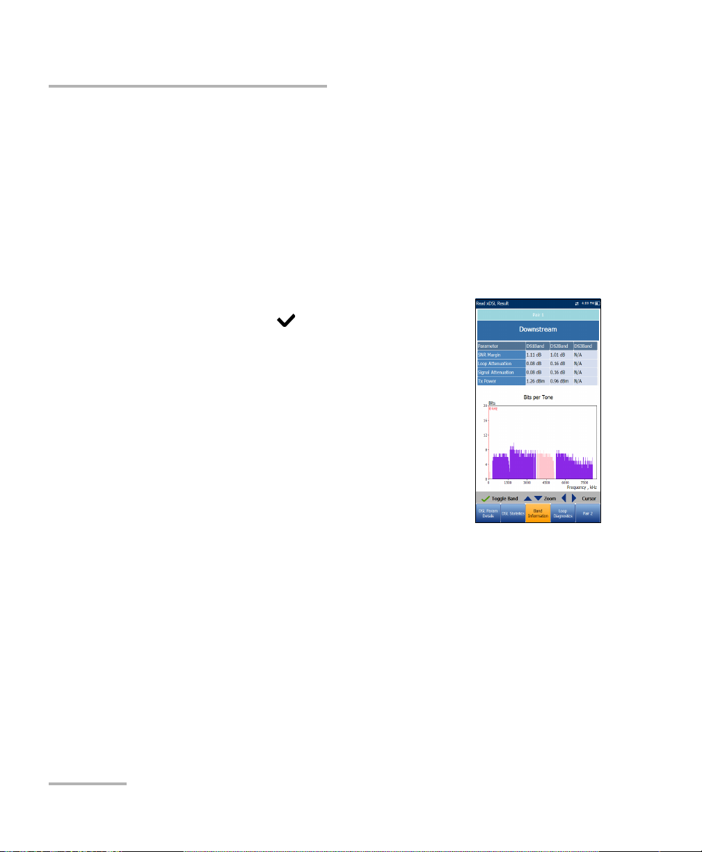
Running DSL/IP Tests and Viewing Results
Band Information
Band Information
The Band Information tab allows you to view a list of individual upstream
or downstream band parameter details.
When the Tes t I nter f ace for Auto or Manual Test is set to ADSL2+ or
VDSL2 bonding mode, there will be 2 pages of results, one for each DSL
line-pair.
To access the second-pair results, press the Pair 1/2 function key at the
bottom-right of the screen.
The page contains Upstream and Downstream
parameters. Press to toggle between bands.
ADSL lists only 1 of each.
VDSL lists US0 to 3 and DS1 to 3 possible
bands, depending on the band plan.
Parameter - Downstream/Upstream
SNR Margin is the measured current
signal-to-noise ratio margin across all active
sub-carriers, as an amount of increased noise
relative to the measured noise power that the
system would be able to tolerate. Only a value
of 6 or above is able to support a bit error rate of 10
-7
.
Loop Attenuation is the current quality of the line and is measured
only once during testing.
Signal Attenuation is the current reduction of signal strength and
is measured periodically when the line is connected.
Tx Power is the upstream/downstream transmitting power for the
selected band.
88 MAX-630
Page 95

Running DSL/IP Tests and Viewing Results
Loop Diagnostics
The Loop Diagnostics tab displays characteristics
and potential problems on the line, in graphical
format. There are 3 separate graphs for each pair:
Downstream SNR per Bin presents the
downstream signal-to-noise ratio per bin.
Downstream ATTN per Bin shows the
downstream attenuation from Hlog (Channel
Response).
Downstream QLN per Bin shows the
downstream PSD noise from quiet line noise.
Press to switch between graphs.
Loop Diagnostics
VDSL2/ADSL2+ Multi-play Test Set 89
Page 96

Running DSL/IP Tests and Viewing Results
Data Tests Summary
Data Tests Summary
The Data Tests Summary tab displays the pass/fail
status of the selected data tests enabled in the
connection setup. A successful WAN connection must
be established in order to view the detailed results.
To view individual data test results:
1.Press the up/down navigation keys to select the
desired test.
2.Press to display the test result details.
Ping Test
The Ping Test tab allows you to view the Pass/Fail summary status of either
a Ping Address or Ping Gateway.
Status is the status of the Ping test performed.
Ping IP/URL is the IP Address or domain name of
the destination being pinged.
Packet Size is the number of bytes sent in one
packet.
Packets Sent is the number of packets sent.
Packets Received is the number of packets
received.
Average Round Trip Time is the duration in
milliseconds (ms) it took the data to reach the
destination device and come back.
Ping IP Address is the destination IP address.
Ping URL is the destination URL address.
90 MAX-630
Page 97

Running DSL/IP Tests and Viewing Results
Data Tests Summary
Packet Size is the number of bytes sent in one packet ranging from 32
through 1200 (default is 32 bytes).
Total Pings is the total number of Ping requests to be sent.
FTP Test
The FTP Test tab displays the FTP download and
upload results configured in the connection setup,
and a pass/fail summary status of whether or not the
file transfer protocol (FTP) was completed
successfully or not.
Except for Auto Test, FTP parameters can be
reconfigured and have information updated from this
tab by using the on-screen FTP Download/Upload
buttons.
Trace Route Test
The Trace Route Test tab allows you to view the
pass/fail status of the IP packet sent to a specified IP
destination, and the path and time taken to do so.
Except for Auto Test, Traceroute parameters can be
reconfigured and have information updated from this
tab by using the on-screen Trace URL or Trace IP
buttons.
VDSL2/ADSL2+ Multi-play Test Set 91
Page 98

Running DSL/IP Tests and Viewing Results
Web Browser
Web Browser
The MaxTester web browser is intended as a tool to view web pages and
confirm internet connections. It is not designed for extensive browsing or
to view complex web pages. Some pages containing images or animated
graphics may not display fully. EXFO suggests that you use the supplied
bookmarks or similar simple web pages for testing.
The web browser results screen is available only if the
software option is enabled. The results screen
contains the following functions:
URL Box displays the current web address to be
connected.
The Go button starts the specified URL or reloads
the previous web page.
On-screen function keys:
Back retrieves the previous web page (if
available). If no web page was previously
browsed, this key is disabled.
Enter Text opens the editor screen allowing you to type an entry.
Bookmarks opens the Bookmarks page allowing you to select a
URL from the list or save the current URL to Bookmarks. You must
press to enable the Bookmarks key.
Refresh reloads the current web page.
STOP halts loading the web page. If the web page has already
loaded, the key is disabled.
For ward takes you to the next web page (if available). If no web
page was browsed after the current page, this key will be disabled.
92 MAX-630
Page 99

Running DSL/IP Tests and Viewing Results
Web Browser
To edit the web address:
1. Press to highlight the URL box.
2. Press to bring up the edit screen and modify the web address. The
edited URL can be used to browse the web page temporarily but it will
not be saved as the Home URL.
To navigate the web browser page:
1. Use the keypad arrow keys to move the on-screen cursor. When the
cursor reaches the edge of the viewing area, the web browser page
scrolls up/down/left/right. The cursor turns into a text edit tool when
scrolling over an editable box or a hand tool when hovering near a
hyperlink.
2. Press to start the desired outcomes.
3. Press to load the Home URL page.
4. Press to exit from the web browser test.
VDSL2/ADSL2+ Multi-play Test Set 93
Page 100

Running DSL/IP Tests and Viewing Results
Bookmarks
Bookmarks
The Bookmarks page allows you to select from a list
of URLs or save the current one.
URL box shows the current URL in the web
browser page.
On-screen function keys:
Add to Bookmarks copies the current URL to
the Bookmarks list above the highlight. When
the list reaches the maximum 9 URLs, the key
is disabled.
Set as URL copies the highlighted URL to the
URL box.
GO saves the bookmarks and starts the web connection using the
address in URL box.
Press to exit from the Bookmarks page avoiding all actions and return
to the web browser page.
94 MAX-630
 Loading...