

Page 1
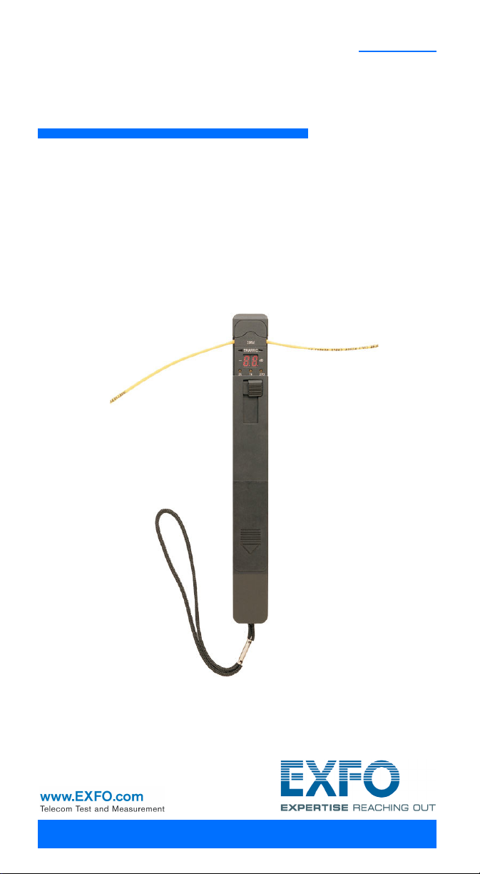
LFD-200
Live Fiber Detector
User Guide
Page 2

Copyright © 2003–2011 EXFO Inc. All rights reserved. No part of this publication may
be reproduced, stored in a retrieval system or transmitted in any form, be it
electronically, mechanically, or by any other means such as photocopying,
recording or otherwise, without the prior written permission of EXFO Inc. (EXFO).
Information provided by EXFO is believed to be accurate and reliable. However, no
responsibility is assumed by EXFO for its use nor for any infringements of patents or
other rights of third parties that may result from its use. No license is granted by
implication or otherwise under any patent rights of EXFO.
EXFO’s Commerce And Government Entities (CAGE) code under the North Atlantic
Treaty Organization (NATO) is 0L8C3.
The information contained in this publication is subject to change without notice.
Trademarks
EXFO’s trademarks have been identified as such. However, the presence or
absence of such identification does not affect the legal status of any trademark.
Units of Measurement
Units of measurement in this publication conform to SI standards and practices.
Version number: 3.0.0
ii
Page 3

Contents
Certification ..................................................................................................... iv
1 Introducing the LFD-200 Live Fiber Detector .......................... 1
Main Features ................................................................................................... 1
Typical Applications .......................................................................................... 2
Available Models .............................................................................................. 3
Adapter Heads .................................................................................................. 4
Power Source .................................................................................................... 5
Conventions ...................................................................................................... 6
2 Operating the Live Fiber Detector ........................................... 7
3 Maintenance ............................................................................ 10
Replacing the 9 V Battery ............................................................................... 11
Adjusting Compartment and Battery Doors .................................................... 12
Recycling and Disposal (Applies to European Union Only) .............................. 12
4 Troubleshooting ...................................................................... 13
Contacting the Technical Support Group ........................................................ 13
Transportation ................................................................................................ 13
5 Warranty .................................................................................. 14
General Information ....................................................................................... 14
Liability ........................................................................................................... 14
Exclusions ....................................................................................................... 15
Certification .................................................................................................... 15
Service and Repairs ......................................................................................... 16
EXFO Service Centers Worldwide .................................................................... 17
A Technical Specifications .......................................................... 18
LFD-200 iii
Page 4

Certification iv
Certification
FCC Information
Electronic test equipment is exempt from Part 15 compliance (FCC) in the United
States. However, compliance verification tests are systematically performed on
most EXFO equipment.
Information
Electronic test equipment is subject to the EMC Directive in the European Union.
The IEC 61326-1 standard prescribes both emission and immunity requirements for
laboratory, measurement, and control equipment.
Page 5
Page 1 of 1
DECLARATION OF CONFORMITY
Application of Council Directive(s): 89/336/EEC - The EMC Directive
93/68/EEC – CE Marking
And their amendments
Manufacturer’s Name and Address:
EXFO Inc. EXFO Europe
400 Godin Avenue Omega Enterprise Park, Electron Way
Quebec City, Quebec Chandlers Ford, Hampshire
G1M 2K2 CANADA SO53 4SE ENGLAND
Tel.: +1 418 683-0211 Tel.: +44 2380 246810
Equipment Type/Environment: Test & Measurement / Industrial
Trade Name/Model No.: Live Fiber Detector / LFD-200
Standard(s) to which Conformity is declared:
EN 61326-1:1997 +A1 :1998 A+ :2001
+A3
:2003
Electrical equipment for measurement, control and laboratory use –
EMC requirements
– Part 1: General requirements
I, the undersigned, hereby declare that the equipment specified above conforms to the above Directive and Standards.
Manufacturer:
Stephen Bull, E. Eng
Vice-President Research and Development
400 Godin Avenue,
Quebec City, Quebec
G1M 2K2 CANADA
November 15, 2001
LFD-200 v
Page 6
Introducing the LFD-200 Live Fiber Detector 1
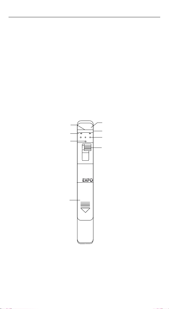
Adapter head
Traffic LED indicators
Tone LED indicators
Slider
Battery compartment
LFD-201 and LFD-203 models
Low battery indicator
Detector port
(inside the unit)
270
1k
2k
Live Fiber Detector
LFD-200
LOW BAT
RIB-CBL
TRAFFIC
Ambient light reduction
design (203 model only)
1 Introducing the LFD-200
Live Fiber Detector
Main Features
The LFD-200 Live Fiber Detector detects traffic and measures optical signals
transmitted through singlemode and multimode fibers without having to disconnect
them.
The Live Fiber Detector uses a safe macrobending technique that does not disrupt
traffic (that is, it eliminates the need to identify a fiber by opening it at the splice
point). At the same time, it avoids damaging or overstressing the fiber. You end up
with accurate and reliable information.
The Live Fiber Detector comes with interchangeable adapter heads stored right into
the unit. It also features a slider that can be locked for hands-free operation.
Page 7
Typical Applications
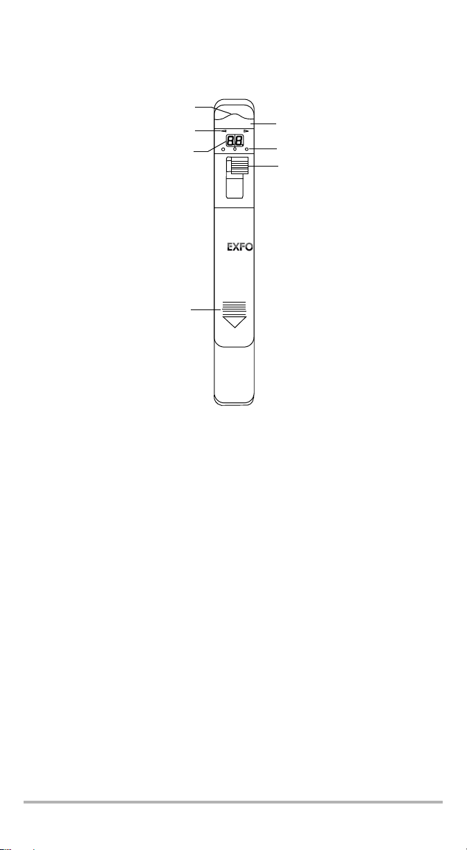
Display
LFD-202 and LFD-202P models
Adapter head
Traffic LED indicators
Tone LED indicators
Slider
Battery compartment
Detector port
(inside the unit)
2701k2k
Live Fiber Detector
LFD-200
dBm
3MM
TRAFFIC
Your Live Fiber Detector can be used to:
verify the presence of a signal before re-routing or maintenance
perform continuity tests
verify cable labeling
LFD-200 2
Page 8

Introducing the LFD-200 Live Fiber Detector 3
Available Models
Four different models are available, as explained in the table below:
Model Description
LFD-201
LFD-202
LFD-202P
LFD-203
Detects continuous signal or signal modulated at 270 Hz, 1 kHz,
and 2 kHz.
Comes with three interchangeable adapter heads: 250 μm,
900 μm, 3 mm.
Detects continuous signal or signal modulated at 270 Hz, 1 kHz,
and 2 kHz.
Displays the relative core power in the fiber (that is, between –
6dbm and –40dBm).
Comes with three interchangeable adapter heads: 250 μm,
900 μm, 3 mm.
Detects continuous signal or signal modulated at 270 Hz, 1 kHz,
and 2 kHz.
Displays the relative core power in the fiber (that is, between
+14dbm and –19dBm).
Comes with three interchangeable adapter heads: 250 μm,
900 μm, 3 mm.
Detects continuous signal or signal modulated at 270 Hz, 1 kHz,
and 2 kHz.
Especially designed for ribbon fibers.
Comes with three interchangeable adapter heads: 3 mm, bare
ribbon, jacketed ribbon.
Page 9

Adapter Heads
Adapter heads
compartment
(door closed)
Pin allowing
the adjustment
of the
compartment
door
P
/
N
S/N
V
ER
.
QST409B
M
FG
.
DATE
Adapter heads
compartment
(door open)
Foam-covered adapter head
to be used with a 900 μm
buffered fiber.
Adapter head with a smooth
surface and a foam perimeter
to be used with a ribbon fiber
or a 250 μm coated fiber.
Slotted adapter head to be
used with a 3 mm or a 2 mm
jacketed fiber (that is, pigtails
and jumpers) or a loose tube
fiber.
The Live Fiber Detector comes with interchangeable adapter heads for simple
conversion and multiple fiber-type testing. The adapter heads are stored in an
internal storage compartment located at the back of the unit.
The LFD-201, LFD-202 and LFD-202P Live Fiber Detector are supplied with three
adapter heads:
LFD-200 4
Page 10

Introducing the LFD-200 Live Fiber Detector 5
Indexing notch
Deep-slot adapter head to be
used with a jacketed ribbon
fiber of up to 12 counts.
Shallow-slot adapter head
to be used with a bare
ribbon fiber of up to 12
counts.
Slotted adapter head to be
used with a 3 mm or a 2 mm
jacketed fiber (that is, pigtails
and jumpers) or a loose tube
fiber.
Indexing notch
Indexing notch
The LFD-203 Live Fiber Detector is supplied with three adapter heads.
The adapter heads for the LFD-203 model have an indexing notch, which is part of
the ambient-light-reduction design.
Power Source
The Live Fiber Detector is powered by a 9 V alkaline battery.
When the battery voltage becomes low, the LOW BAT LED illuminates (LFD-201 and
LFD-203 models) or Lb appears on the display (LFD-202 and LFD-202P models).
The unit will continue to operate for some time, but the battery should be replaced
with a fresh 9 V alkaline battery as soon as possible (see Replacing the 9 V Battery
on page 11).
Page 11

Conventions
Before using the product described in this guide, you should understand the
following conventions:
WARNING
Indicates a potentially hazardous situation which, if not avoided,
could result in death or serious injury. Do not proceed unless you
understand and meet the required conditions.
CAUTION
Indicates a potentially hazardous situation which, if not avoided,
may result in minor or moderate injury. Do not proceed unless you
understand and meet the required conditions.
CAUTION
Indicates a potentially hazardous situation which, if not avoided,
may result in component damage. Do not proceed unless you
understand and meet the required conditions.
IMPORTANT
Refers to information about this product you should not overlook.
LFD-200 6
Page 12

Operating the Live Fiber Detector 7
2 Operating the Live Fiber
Detector
To operate the Live Fiber Detector:
1. Choose an adapter head for the type of fiber to be tested (see Adapter Heads on
page 4).
2. Slide the adapter head into the mating slotted channel, applying a slight
downward pressure.
If you have the LFD-203 Live Fiber Detector model, be sure to place the adapter
with the indexing notch facing the front of the unit.
3. Place the fiber gently in the alignment groove of the adapter head.
4. Slide the switch upward.
OR
For hands-free operation, slide the switch upward and over to the right to lock it
in place.
Note: Each time the switch is operated, the Live Fiber Detector performs a
self-test. During the self-test, all LEDs will illuminate and will turn off
after approximately 0.5 seconds.
Page 13

5. If you want to send a modulated signal, connect the unit to a source (such as
Fiber under test
FOT-700 Fiber-Optic Tester LFD-200 Live Fiber Detector
FIBER-OPTIC TESTER
FOT-700
ZERO
START
ON/OFF
MODE
dB/dB/W
CW
DELETE
STORE
REF
AUTO
2701k2k
Live Fiber Detector
LFD-200
LOW BAT
RIB-CBL
TRAFFIC
EXFO FOT-700 Fiber-Optic Tester, FLS-130A Fiber-Optic Light Source or
FLS-210A Variable Light Source), as illustrated below.
Note: The recommended wavelength is 1550 nm for tone identification. If you
use another wavelength than 1310 nm or 1550 nm, the Live Fiber
Detector will still detect the signal, but the specifications are not
guaranteed.
6. Evaluate the presence and direction of light transmission.
If the traffic LED indicator located on the left-hand side is illuminated, the
traffic is coming from the right.
If the traffic LED indicator located on the right-hand side is illuminated, the
traffic is coming from the left.
A beep also indicates the presence of traffic.
7. Identify the tone.
If you have connected a source to send a modulated signal, one of the 270 Hz,
1Hz, or 2kHz tone LED indicator will be illuminated.
Note: During the operation at the lowest levels of tone detection
(approximately –40 dB core power), the tone LEDs may flicker, which
indicates that the minimum range of detection was reached.
LFD-200 8
Page 14

Operating the Live Fiber Detector 9
8. If you have the LFD-202 or LFD-202P Live Fiber Detector model, look at the
relative core power of the fiber on the display.
LFD-202 LFD-202P
Displays the relative core power with a
negative dB value between –6 and
–40 dBm.
If the core power is greater than 0 dBm,
The unit displays HI.
Traffic LED indicators are valid.
If the core power is below –40 dB,
The unit displays LO.
Traffic LED indicators are no longer
valid.
Displays the relative core power with a
dB value between +4 and –19 dBm.
If the core power is greater than
+15dBm,
The unit displays HI.
Traffic LED indicators are valid.
If the core power is below –19 dB,
The unit displays LO.
Traffic LED indicators are no longer
valid.
Page 15

3 Maintenance
To help ensure long, trouble-free operation:
Always inspect fiber-optic connectors before using them and clean them if
necessary.
Keep the unit free of dust.
Clean the unit casing and front panel with a cloth slightly dampened with water.
Store unit at room temperature in a clean and dry area. Keep the unit out of
direct sunlight.
Avoid high humidity or significant temperature fluctuations.
Avoid unnecessary shocks and vibrations.
If any liquids are spilled on or into the unit, turn off the power immediately,
disconnect from any external power source, remove the batteries and let the
unit dry completely.
WARNING
Use of controls, adjustments, and procedures for operation and
maintenance other than those specified herein may result in
hazardous radiation exposure.
To clean detector ports:
1. If the detector is dusty, blow dry with compressed air.
2. Being careful not to touch the soft end of the swab, moisten a cleaning tip with
only one drop of isopropyl alcohol.
IMPORTANT
Alcohol may leave traces if used abundantly. Do not use bottles that
distribute too much alcohol at a time.
3. While applying light pressure (to avoid breaking the detector window), gently
rotate the cleaning tip on the detector window.
4. Repeat step 3 with a dr y cleaning tip or blow dr y with compressed air.
5. Discard the cleaning tips after one use.
LFD-200 10
Page 16

Maintenance 11
Replacing the 9 V Battery
When the battery voltage becomes low, the LOW BAT LED illuminates (LFD-201 and
LFD-203 models) or Lb appears on the display (LFD-202 and LFD-202P models).
The unit will continue to operate for some time, but the battery should be replaced
with a fresh 9 V alkaline battery as soon as possible.
To replace the 9 V battery:
1. Turn off the Live Fiber Detector.
2. Open the battery compartment door located at the front of the unit.
3. Change the 9 V batter y, respecting the polarity.
4. Close the battery compartment door.
Page 17

Adjusting Compartment and Battery Doors
3 4
With time and handling, the adapter head compartment door, as well as the battery
door may require adjustment to ensure the proper operation of your Live Fiber
Detector.
To adjust the door(s):
1. Open the door you want to adjust by pressing on it and sliding it away from the
Live Fiber Detector.
2. Locate the adjustment screw.
3. With a flat-head screwdriver, press down on the small silver ball until the head
of the screwdriver fits into the small grooves on each side of the screw.
Note: You must press down on the silver ball to be able to turn the screw.
4. Turn the screw clockwise or counterclockwise, on whether you want to slacken
or tighten the screw.
5. Close the door.
Recycling and Disposal (Applies to European
Union Only)
For complete recycling/disposal information as per European Directive WEEE
2002/96/EC, visit the EXFO Web site at www.exfo.com/recycle.
LFD-200 12
Page 18

Troubleshooting 13
4 Troubleshooting
Contacting the Technical Support Group
To obtain after-sales service or technical support for this product, contact EXFO at
one of the following numbers. The Technical Support Group is available to take your
calls from Monday to Friday, 8:00 a.m. to 7:00 p.m. (Eastern Time in North America).
For detailed information about technical support, visit the EXFO Web site at
www.exfo.com.
Technical Support Group
400 Godin Avenue
Quebec (Quebec) G1M 2K2
CANADA
To accelerate the process, please have information such as the name and the serial
number (see the product identification label), as well as a description of your
problem, close at hand.
Transportation
Maintain a temperature range within specifications when transporting the unit.
Transportation damage can occur from improper handling. The following steps are
recommended to minimize the possibility of damage:
Pack the unit in its original packing material when shipping.
Avoid high humidity or large temperature fluctuations.
Keep the unit out of direct sunlight.
Avoid unnecessary shocks and vibrations.
1 866 683-0155 (USA and Canada)
Tel.: 1 418 683-5498
Fax: 1 418 683-9224
support@exfo.com
Page 19

5 Warranty
General Information
EXFO Inc. (EXFO) warrants this equipment against defects in material and
workmanship for a period of one year from the date of original shipment. EXFO also
warrants that this equipment will meet applicable specifications under normal use.
During the warranty period, EXFO will, at its discretion, repair, replace, or issue
credit for any defective product, as well as verify and adjust the product free of
charge should the equipment need to be repaired or if the original calibration is
erroneous. If the equipment is sent back for verification of calibration during the
warranty period and found to meet all published specifications, EXFO will charge
standard calibration fees.
IMPORTANT
The warranty can become null and void if:
unit has been tampered with, repaired, or worked upon by
unauthorized individuals or non-EXFO personnel.
warranty sticker has been removed.
case screws, other than those specified in this guide, have been
removed.
case has been opened, other than as explained in this guide.
unit serial number has been altered, erased, or removed.
unit has been misused, neglected, or damaged by accident.
THIS WARRANTY IS IN LIEU OF ALL OTHER WARRANTIES EXPRESSED, IMPLIED,
OR STATUTORY, INCLUDING, BUT NOT LIMITED TO, THE IMPLIED WARRANTIES OF
MERCHANTABILITY AND FITNESS FOR A PARTICULAR PURPOSE. IN NO EVENT
SHALL EXFO BE LIABLE FOR SPECIAL, INCIDENTAL, OR CONSEQUENTIAL
DAMAGES.
Liability
EXFO shall not be liable for damages resulting from the use of the product, nor shall
be responsible for any failure in the performance of other items to which the
product is connected or the operation of any system of which the product may be a
part.
EXFO shall not be liable for damages resulting from improper usage or unauthorized
modification of the product, its accompanying accessories and software.
LFD-200 14
Page 20

Warranty 15
Exclusions
EXFO reserves the right to make changes in the design or construction of any of its
products at any time without incurring obligation to make any changes whatsoever
on units purchased. Accessories, including but not limited to fuses, pilot lamps,
batteries and universal interfaces (EUI) used with EXFO products are not covered by
this warranty.
This warranty excludes failure resulting from: improper use or installation, normal
wear and tear, accident, abuse, neglect, fire, water, lightning or other acts of nature,
causes external to the product or other factors beyond the control of EXFO.
IMPORTANT
EXFO will charge a fee for replacing optical connectors that were
damaged due to misuse or bad cleaning.
Certification
EXFO certifies that this equipment met its published specifications at the time of
shipment from the factory.
Page 21

Service and Repairs
EXFO commits to providing product service and repair for five years following the
date of purchase.
To send any equipment for service or repair:
1. Call one of EXFO’s authorized service centers (see EXFO Service Centers
Worldwid e on page 17). Support personnel will determine if the equipment
requires service, repair, or calibration.
2. If equipment must be returned to EXFO or an authorized service center, support
personnel will issue a Return Merchandise Authorization (RMA) number and
provide an address for return.
3. If possible, back up your data before sending the unit for repair.
4. Pack the equipment in its original shipping material. Be sure to include a
statement or report fully detailing the defect and the conditions under which it
was observed.
5. Return the equipment, prepaid, to the address given to you by support
personnel. Be sure to write the RMA number on the shipping slip. EXFO will
refuse and return any package that does not bear an RMA number.
Note: A test setup fee will apply to any returned unit that, after test, is found to
meet the applicable specifications.
After repair, the equipment will be returned with a repair report. If the equipment is
not under warranty, you will be invoiced for the cost appearing on this report. EXFO
will pay return-to-customer shipping costs for equipment under warranty. Shipping
insurance is at your expense.
Routine recalibration is not included in any of the warranty plans. Since
calibrations/verifications are not covered by the basic or extended warranties, you
may elect to purchase FlexCare Calibration/Verification Packages for a definite
period of time. Contact an authorized service center (see EXFO Service Centers
Worldwid e on page 17).
LFD-200 16
Page 22

Warranty 17
EXFO Service Centers Worldwide
If your product requires servicing, contact your nearest authorized service center.
EXFO Headquarters Service Center
400 Godin Avenue
Quebec (Quebec) G1M 2K2
CANADA
EXFO Europe Service Center
Omega Enterprise Park, Electron Way
Chandlers Ford, Hampshire S053 4SE
ENGLAND
EXFO Telecom Equipment
(Shenzhen) Ltd.
3rd Floor, Building 10,
Yu Sheng Industrial Park (Gu Shu Crossing),
No. 467,
National Highway 107,
Xixiang, Bao An District,
Shenzhen, China, 518126
1 866 683-0155 (USA and Canada)
Tel.: 1 418 683-5498
Fax: 1 418 683-9224
quebec.service@exfo.com
Tel.: +44 2380 246810
Fax: +44 2380 246801
europe.service@exfo.com
Tel: +86 (755) 2955 3100
Fax: +86 (755) 2955 3101
beijing.service@exfo.com
Page 23

A Technical Specifications
SPECIFICATIONS
LFD-201, LFD-202 and LFD-202E
Optical Characteristics, Typical
Optical tone receiver 270 Hz, 1 kHz, 2 kHz
Detection technique Non-destructive macrobending
Loss < 0.6 dB at 1310 nm
Spectral response 800 nm to 1650 nm
Minimum fiber slack 1.2 cm (
1
/2 in) required for detection
Core Power Detection, Typical
a
LFD-201 0 dBm to –40 dBm
LFD-202 0 dBm to –40 dBm
LFD-202E 23 dBm to –50 dBm
Fiber Compatibility
Dual window, singlemode 8 μm to 10 μm core diameter
Coating diameter 250 μm diameter
Coating High refractive index, acrylate
Note
a. At 1550 nm.
IMPORTANT
The following technical specifications can change without notice.
The information presented in this section is provided as a reference
only. To obtain this product’s most recent technical specifications,
visit the EXFO Web site at www.exfo.com.
LFD-200 18
Page 24

NOTICE
抩⛙
CHINESE REGULATION ON RESTRICTION OF HAZARDOUS SUBSTANCES
₼⦌␂ℝ☀⹂䓸德棟Ⓟ䤓屓⸩
NAMES AND CONTENTS OF THE TOXIC OR HAZARDOUS SUBSTANCES OR ELEMENTS
CONTAINED IN THIS EXFO PRODUCT
▔⚺⦷㦻 EXFO ℶ❐₼䤓㦘㹡㦘⹂䓸德㒥⏒侯䤓⚜䱿✛⚺摞
MARKING REQUIREMENTS
㪖㽷尐㻑
O
Indicates that this toxic or hazardous substance contained in all of the homogeneous
materials for this part is below the limit requirement in SJ/T11363-2006
嫷䯉年㦘㹡㦘⹂䓸德⦷年捷ↅ㓏㦘⧖德㧟㠨₼䤓⚺摞⧖⦷ SJ/T11363-2006 㪖屓⸩䤓棟摞尐
㻑ⅴₚᇭ
X
Indicates that this toxic or hazardous substance contained in at least one of the
homogeneous materials used for this part is above the limit requirement in SJ/T11363-2006
嫷䯉年㦘㹡㦘⹂䓸德咂⺠⦷年捷ↅ䤓㩟⧖德㧟㠨₼䤓⚺摞怔⒉ SJ/T11363-2006 㪖屓⸩䤓
棟摞尐㻑ᇭ
Par t Na me
捷ↅ⚜䱿
Toxic or hazardous Substances and Elements
㦘㹡㦘⹂䓸德✛⏒侯
Lead
杔
(Pb)
Mercury
㻭
(Hg)
Cadmium
椣
(Cd)
Hexavalent
Chromium
⏼ↆ杻
(Cr VI)
Pol yb ro mi na te d
biphenyls
⮩䅃勣啾
(PBB)
Pol yb r om in at ed
diphenyl ethers
⮩䅃ℛ啾搩
(PBDE)
Enclosure
⮥⮂
OO O O O O
Electronic and
electrical
sub-assembly
䟄✛䟄兓ↅ
XO X O X X
Optical
sub-assembly
a
⏘ⷵ兓ↅ
a
a. If applicable.
Ⱁ㨫抑䞷ᇭ
XO O O O O
Mechanical
sub-assembly
a
㧉㬿兓ↅ
a
OO O O O O
Pro duct
ℶ❐
Environmental protection use period (years)
䘾⬒≬㔳∎䞷㦮棟 ( )
Logo
㪖㉦
This Exfo product
㦻 EXFO ℶ❐
10
Battery
a
䟄㻯
a
a. If applicable.
Ⱁ㨫抑䞷ᇭ
5
Page 25

P/N: 1061979
CORPORATE
HEADQUARTERS
www.EXFO.com · info@exfo.com
400 Godin Avenue Quebec (Quebec) G1M 2K2 CANADA
Tel.: 1 418 683-0211 · Fax: 1 418 683-2170
EXFO AMERICA 3400 Waterview Parkway
EXFO EUROPE Omega Enterprise Park,
EXFO ASIA-PACIFIC 100 Beach Road,
EXFO CHINA Beijing Global Trade Center,
EXFO SERVICE
ASSURANCE
EXFO NETHAWK Elektroniikkatie 2 FI-90590 Oulu, FINLAND
TOLL-FREE (USA and Canada) 1 800 663-3936
© 2011 EXFO Inc. All rights reserved.
Printed in Canada (2011-10)
Suite 100
Electron Way
#22-01/03 Shaw Tower
Tower C, Room 1207,
36 North Third Ring Road
East, Dongcheng District
270 Billerica Road Chelmsford MA, 01824 USA
Richardson, TX 75080 USA
Tel.: 1 972-761-927 · Fax: 1 972-761-9067
Chandlers Ford, Hampshire S053 4SE ENGLAND
Tel.: +44 2380 246810 · Fax: +44 2380 246801
SINGAPORE 189702
Tel.: +6563338241 · Fax: +6563338242
Beijing 100013 P. R. CHINA
Tel.: +86 (10) 5825 7755
Fax: +86 (10) 5825 7722
Tel.: 1 978 367-5600 · Fax: 1 978 367-5700
Tel.: +358 (0) 403 010 300
Fax: +358 (0) 8 564 5203
 Loading...