

Page 1
IQS-9100/9100B
Optical Switch for IQS platforms
User Guide
Page 2

Copyright © 2006–2012 EXFO Inc. All rights reserved. No part of this
publication may be reproduced, stored in a retrieval system or transmitted
in any form, be it electronically, mechanically, or by any other means such
as photocopying, recording or otherwise, without the prior written
permission of EXFO Inc. (EXFO).
Information provided by EXFO is believed to be accurate and reliable.
However, no responsibility is assumed by EXFO for its use nor for any
infringements of patents or other rights of third parties that may result from
its use. No license is granted by implication or otherwise under any patent
rights of EXFO.
EXFO’s Commerce And Government Entities (CAGE) code under the North
Atlantic Treaty Organization (NATO) is 0L8C3.
The information contained in this publication is subject to change without
notice.
Trademarks
EXFO’s trademarks have been identified as such. However, the presence
or absence of such identification does not affect the legal status of any
trademark.
Units of Measurement
Units of measurement in this publication conform to SI standards and
practices.
Patents
EXFO’s Universal Interface is protected by US patent 6,612,750.
Version number: 4.0.0
ii IQS-9100/9100B
Page 3

Contents
Contents
Certification Information ........................................................................................................v
1 Introducing the IQS-9100/9100B Optical Switch ........................................ 1
Main Features .........................................................................................................................1
Available Models ....................................................................................................................2
Basic Switching Principles .....................................................................................................10
Typical Applications ..............................................................................................................12
Conventions ..........................................................................................................................16
2 Getting Started with Your Optical Switch ................................................ 17
Inserting and Removing Test Modules ..................................................................................18
Starting the Optical Switch Application ................................................................................22
Exiting the Application .........................................................................................................25
3 Operating the Optical Switch .................................................................... 27
Installing the EXFO Universal Interface (EUI) .........................................................................28
Cleaning and Connecting Optical Fibers ...............................................................................29
Optimizing the Application for Repeatability ........................................................................31
Selecting Configurations with the 1 x n Model .....................................................................32
Selecting Configurations with the 2 x 2 Model (IQS-9100 Optical Switch only) ....................34
Selecting Configurations with the 2 x 4 Model (IQS-9100 Optical Switch only) ....................35
Saving and Recalling Configurations .....................................................................................36
4 Controlling Multiple Optical Switch Modules .......................................... 39
Starting a Multimodule Application ......................................................................................39
Selecting Modules to Control ...............................................................................................40
Setting Parameters for Multiple Modules ..............................................................................41
Controlling a Single IQS-9100/9100B Optical Switch ............................................................44
Navigating and Closing Multiple Module Windows ..............................................................45
5 Monitoring Optical Switch Modules ......................................................... 47
Using Monitor Windows .......................................................................................................47
Using QuickTools ...................................................................................................................50
6 Maintenance ............................................................................................... 53
Cleaning Fixed Connectors ....................................................................................................54
Cleaning EUI Connectors ......................................................................................................56
Recycling and Disposal (Applies to European Union Only) ....................................................58
Optical Switch iii
Page 4

Contents
7 Troubleshooting ..........................................................................................59
Solving Common Problems ...................................................................................................59
Obtaining Online Help ..........................................................................................................60
Contacting the Technical Support Group ..............................................................................61
Transportation ......................................................................................................................62
8 Warranty ......................................................................................................63
General Information .............................................................................................................63
Liability .................................................................................................................................63
Exclusions .............................................................................................................................64
Certification ..........................................................................................................................64
Service and Repairs ...............................................................................................................65
EXFO Service Centers Worldwide ..........................................................................................66
A Technical Specifications ..............................................................................67
B SCPI Command Reference ..........................................................................69
Quick Reference Command Tree ...........................................................................................70
Product-Specific Commands—Description ............................................................................71
Index .................................................................................................................91
iv IQS-9100/9100B
Page 5

Certification Information
Certification Information
North America Regulatory Statement on Product
Safety
This unit was certified by an agency approved in both Canada and the
United States of America. It has been evaluated according to applicable
North American approved standards for product safety for use in Canada
and the United States.
Electronic test and measurement equipment is exempt from FCC part 15,
subpart B compliance in the United States of America and from ICES-003
compliance in Canada. However, EXFO Inc. makes reasonable efforts to
ensure compliance to the applicable standards.
The limits set by these standards are designed to provide reasonable
protection against harmful interference when the equipment is operated in
a commercial environment. This equipment generates, uses, and can
radiate radio frequency energy and, if not installed and used in accordance
with the user guide, may cause harmful interference to radio
communications. Operation of this equipment in a residential area is likely
to cause harmful interference in which case the user will be required to
correct the interference at his own expense.
Modifications not expressly approved by the manufacturer could void the
user's authority to operate the equipment.
Optical Switch v
Page 6

Certification Information
Page 1 of 1
DECLARATION OF CONFORMITY
Application of Council Directive(s):
2006/95/EC – The Low Voltage Directive
2004/108/EC – The EMC Directive
93/68/EEC – CE Marking
And their amendments
Manufacturer’s Name and Address:
EXFO Inc. EXFO Europe
400 Godin Avenue Omega Enterprise Park, Electron Way
Quebec City, Quebec Chandlers Ford, Hampshire
G1M 2K2 CANADA SO53 4SE ENGLAND
Tel.: +1 418 683-0211 Tel.: +44 2380 246810
Equipment Type/Environment:
Test & Measurement / Industrial
Trade Name/Model No.:
Optical Switch / IQS-9100 & IQS-9100B
Standard(s) to which Conformity is declared:
EN 61010-1:2001 Edition 2.0
Safety requirements for electrical equipment for measurement,
control, and laboratory use
– Part 1: General requirements
EN 61326-1:2006
Electrical equipment for measurement, control and laboratory use –
EMC requirements
– Part 1: General requirements
I, the undersigned, hereby declare that the equipment specified above conforms to the above Directive and Standards.
Manufacturer:
Stephen Bull, E. Eng
Vice-President Research and Development
400 Godin Avenue,
Quebec City, Quebec
G1M 2K2 CANADA
November 23, 2011
European Community Declaration of Conformity
vi IQS-9100/9100B
Page 7

1 Introducing the
IQS-9100/9100B Optical Switch
Main Features
The IQS-9100/9100B Optical Switch provides fiber-to-fiber positioning of
optical signals for a number of optical applications. This module, which
exists in various models depending on the number of optical ports and
configuration options it has, allows you to quickly switch light from one
fiber to another.
This optical switch can be controlled using applications available in the
IQS Manager software.
The applications can control one or more modules at a time and allow
for various configurations.
The configurations can be modified at any time and can be saved for
future use, allowing you to save time and be more efficient.
The IQS-9100/9100B Optical Switch supports local control (via the
IQS Manager software) and remote control (through GPIB, RS-232, or
Ethernet TCP/IP using SCPI commands or the provided LabVIEW drivers).
For more information, refer to the IQS platform user guide.
Optical Switch 1
Page 8

Introducing the IQS-9100/9100B Optical Switch
Available Models
Available Models
The Optical Switch comes in two different models:
Model Features
IQS-9100 singlemode or multimode
available in 1 x n and 2 x n configurations
IQS-9100B
singlemode
available in 1 x n configuration
The different available switch configurations are shown in the following
figures, except for the 1 x 8 and the 1 x 24 optical switch models.
Note: Actual connectors may differ from those depicted in the illustrations.
2 IQS-9100/9100B
Page 9
Introducing the IQS-9100/9100B Optical Switch
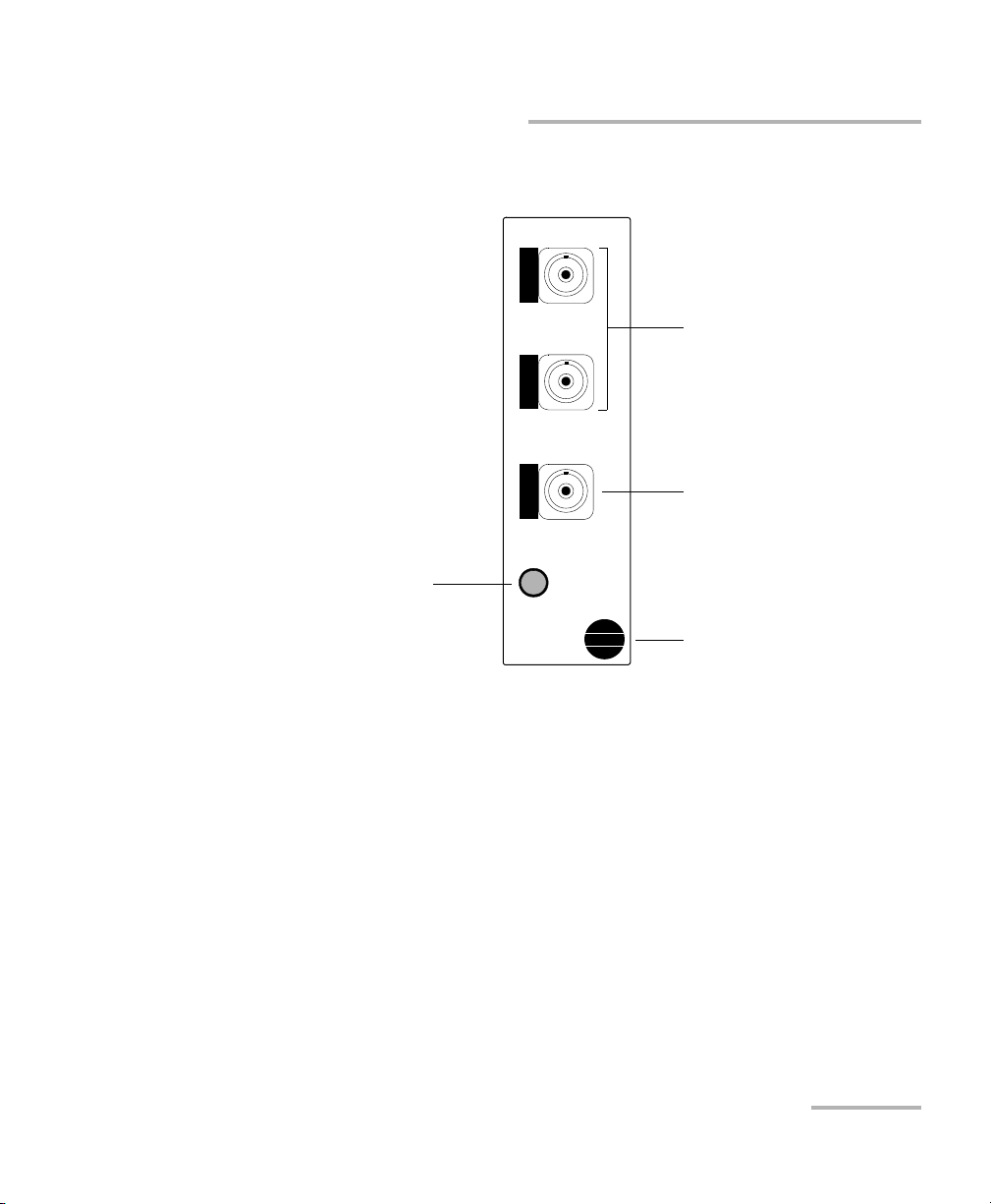
1 x 2 Optical Switch Module
Switch ports 1 and 2
Common port
1 x 2
IQS-9100
Optical Switch
Retaining screw knob
LED push button
Available Models
Optical Switch 3
Page 10
Introducing the IQS-9100/9100B Optical Switch
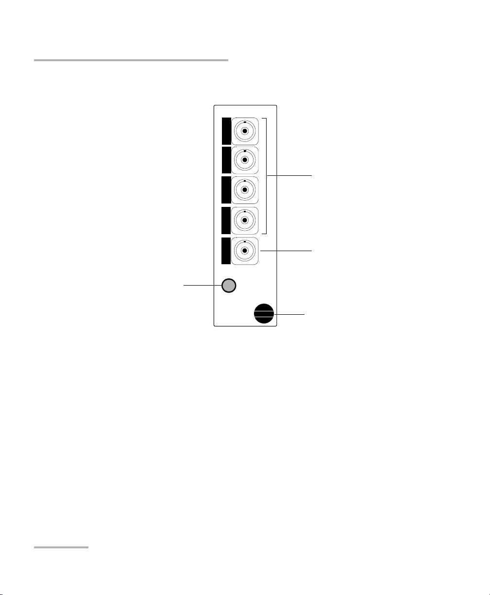
1 x 4 Optical Switch Module
Switch ports 1 to 4
Common port
1 x 4
IQS-9100
Optical Switch
Retaining screw knob
LED push button
Available Models
4 IQS-9100/9100B
Page 11
Introducing the IQS-9100/9100B Optical Switch
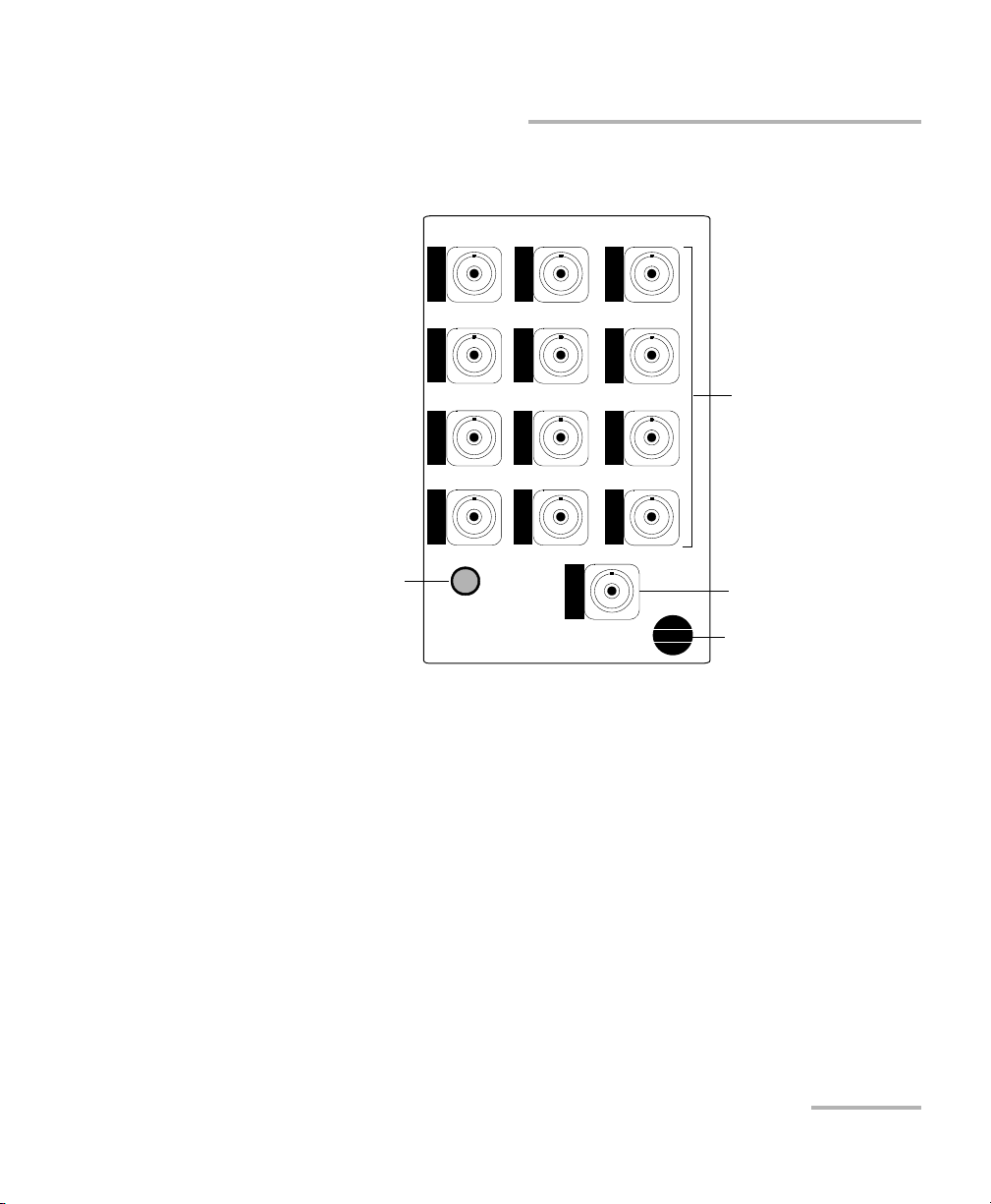
1 x 12 Optical Switch Module
Switch ports
1 to 12
Retaining screw knob
IQS-9100
1 x 12 Optical Switch
Common port
LED push button
Available Models
Optical Switch 5
Page 12
Introducing the IQS-9100/9100B Optical Switch
Common port
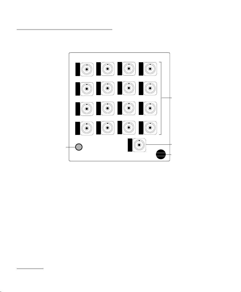
1 x 16 Optical Switch Module
IQS-9100
1 x 16 Optical Switch
Switch ports
1 to 16
Retaining screw
knob
LED push button
Available Models
6 IQS-9100/9100B
Page 13
Introducing the IQS-9100/9100B Optical Switch
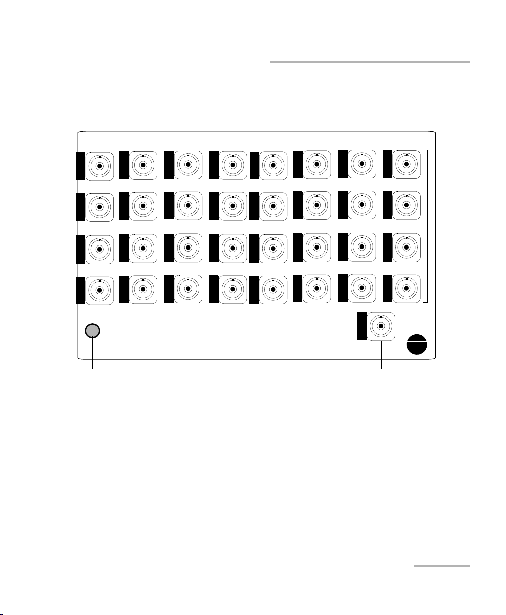
Switch
ports
1to32
Common
port
1 x 32 Optical Switch Module
IQS-9100
1 x 32 Optical Switch
Retaining
screw knob
LED push button
Available Models
Optical Switch 7
Page 14
Introducing the IQS-9100/9100B Optical Switch
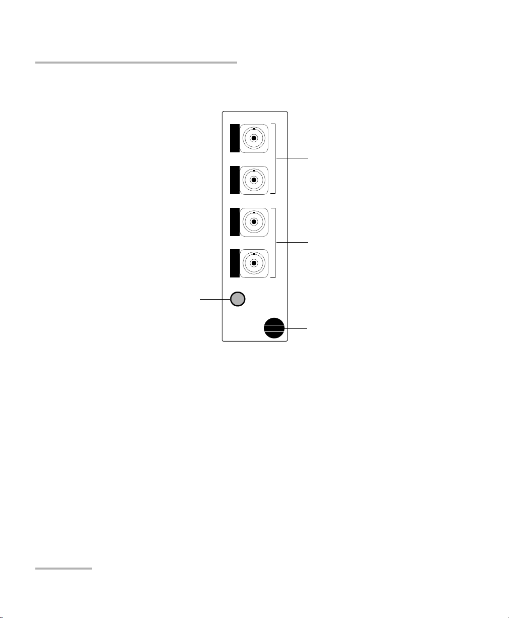
2 x 2 Optical Switch Module
(IQS-9100 Optical Switch only)
Output ports
O1 and O2
Input ports
I1 and I2
2 x 2
IQS-9100
Optical Switch
Retaining screw knob
LED push button
Available Models
8 IQS-9100/9100B
Page 15
Introducing the IQS-9100/9100B Optical Switch
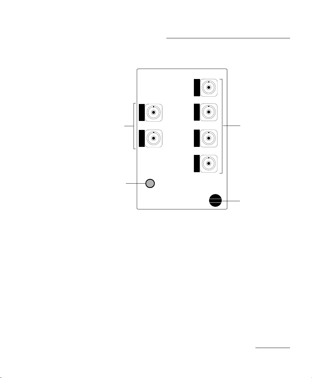
2 x 4 Optical Switch Module
(IQS-9100 Optical Switch only)
Output ports
O1 and O4
Input ports
I1 and I2
IQS-9100
2 x 4 Optical Switch
Retaining screw knob
LED push button
Available Models
Optical Switch 9
Page 16
Introducing the IQS-9100/9100B Optical Switch
Switch ports
Common port
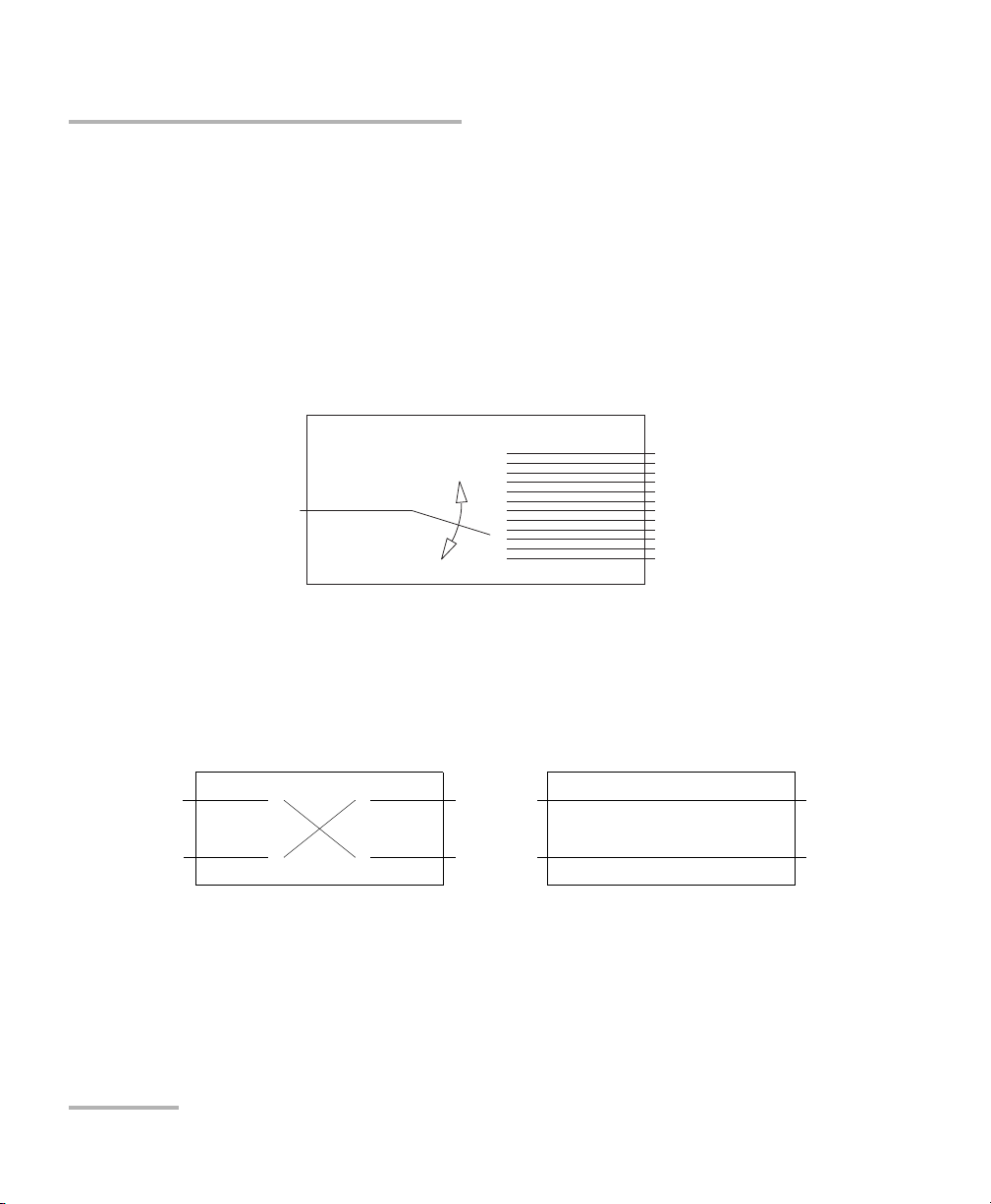
1 x N Optical Switch Principle
I1
I2
O1O2I1
I2
O1
O2
2 x 2 Optical Switch Principle
(IQS-9100 Optical Switch only)
INSERTED STATE BYPASS STATE
Basic Switching Principles
Basic Switching Principles
The switch ports of 1 x N optical switches are numbered on the front panel,
while the common port is identified with a "C."
These switches are bidirectional. This means that the optical signal can
either enter through the common port and be directed toward any switch
port, or enter through any switch port and then be directed toward the
common port.
The IQS-9100-02-02 (2 2 model) is also a bidirectional switch. The two
positions for this switch are known as inserted state and bypass state.
10 IQS-9100/9100B
Page 17
Introducing the IQS-9100/9100B Optical Switch
O1
O2
O3
O4
I1
I2
O1
O2
O3
O4
I1
I2
I1
O1
O2
O3
O4
I1
I2
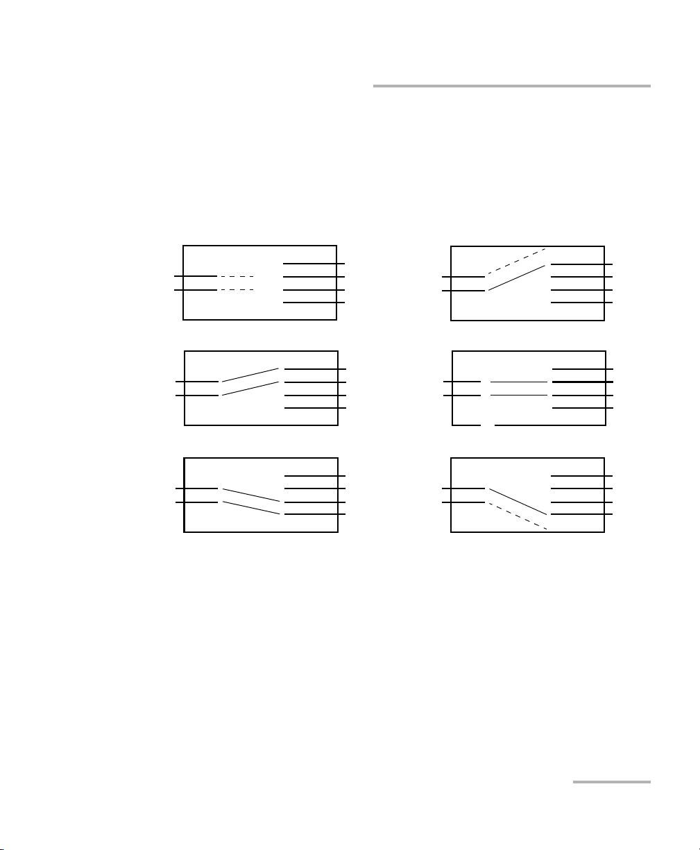
2 x 4 Optical Switch Principle
(IQS-9100 Optical Switch only)
I2
O1
O2
O3
O4
O1
O2
O3
O4
I1
I2
I1
I2
O1
O2
O3
O4
I1
I2
No continuity - Both ports No continuity - Port I1
No continuity - Port I2
I1
I2
Basic Switching Principles
The IQS-9100-02-04 (2 4 model) is also a bidirectional switch. As
illustrated in the following figure, the IQS-9100-02-04 can be set to six
positions. In three of these positions, one or both input channels do not
transmit light to output ports.
Optical Switch 11
Page 18
Introducing the IQS-9100/9100B Optical Switch
IQS-1100
Device 1
Device 2
Device 4
Device 3
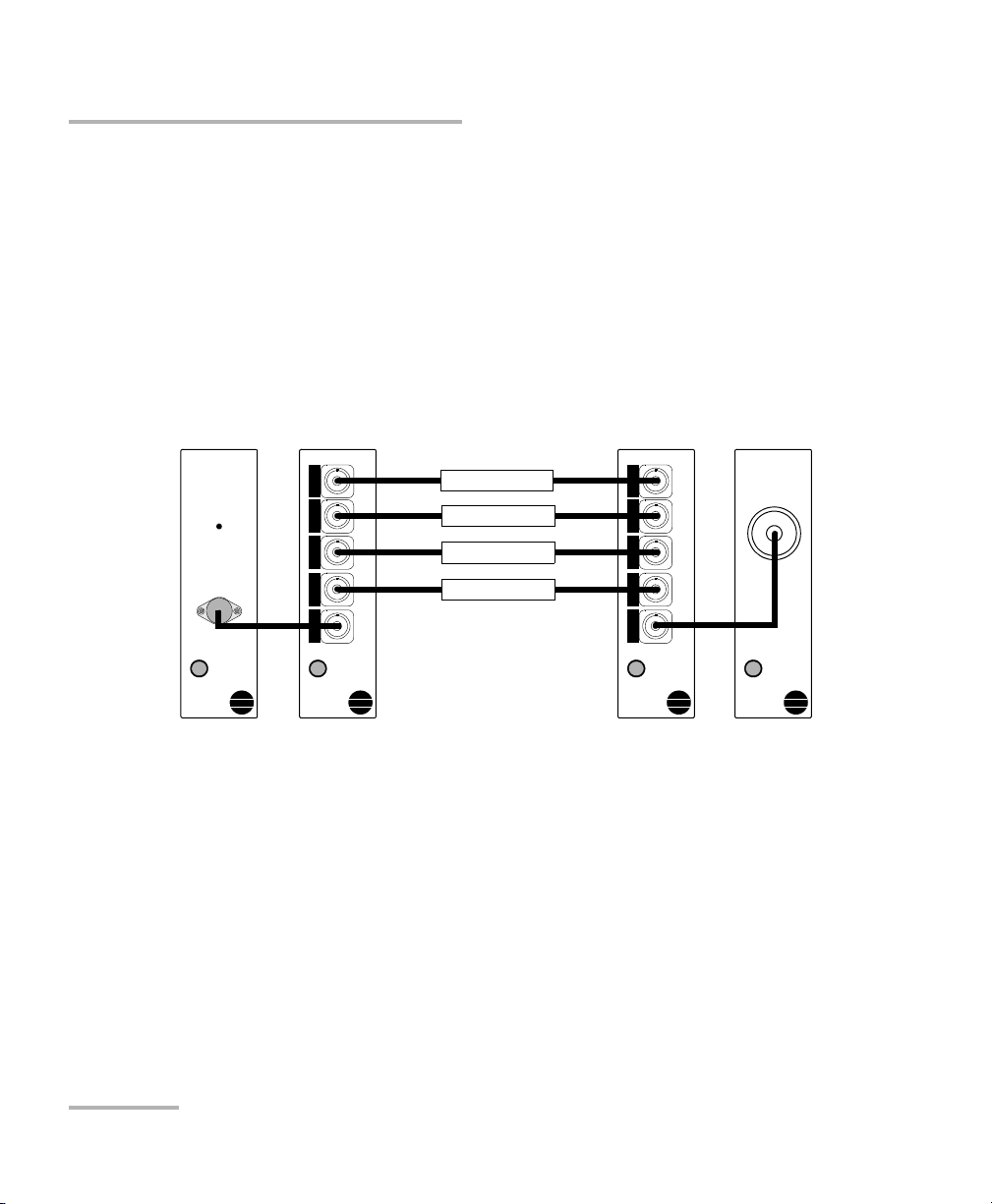
Light Source
IQS-2100
ACTIVE
1 x 4
IQS-9100
Optical Switch
1 x 4
IQS-9100
Optical Switch
Power Meter
Typic a l Ap pl ic ation s
Typical Applications
Testing with Multiple Devices
Using two optical switches, a light source and a power meter, it is possible
to perform automated qualification and production testing for multiple
devices.
To perform automated qualification and production testing for
multiple devices:
1. Connect the modules and DUTs as shown below.
2. Measure the DUTs with the power meter.
12 IQS-9100/9100B
Page 19
Introducing the IQS-9100/9100B Optical Switch
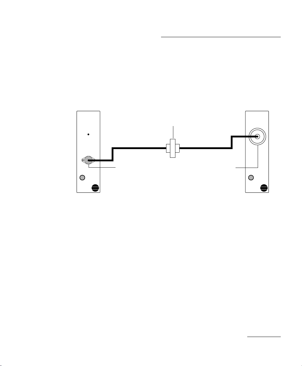
Light Source
IQS-2100
ACTIVE
Power Meter
IQS-1100
Bulkhead connector
Light source
output port
Power meter
detector port
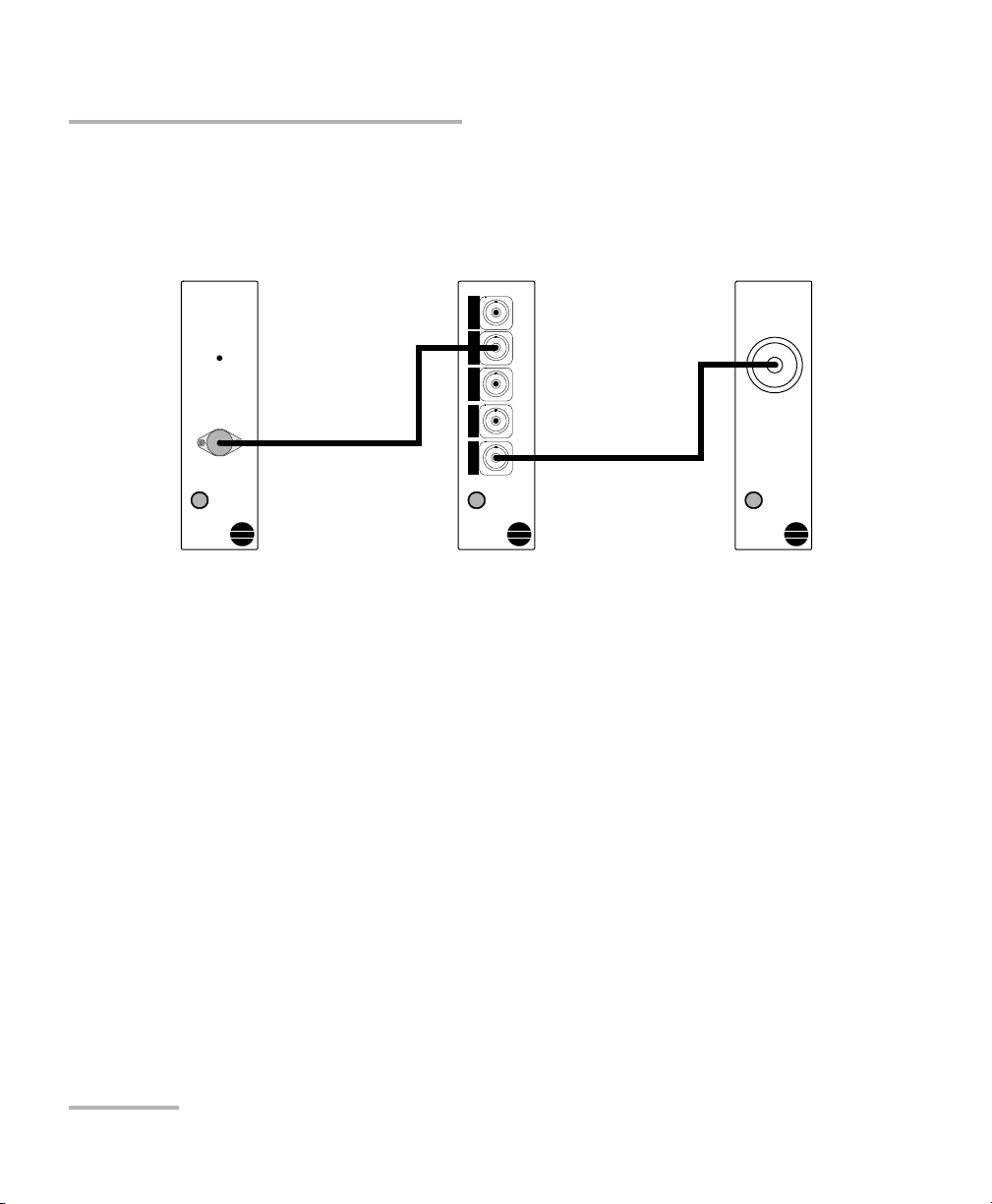
Typical Applications
Measuring Optical Switch Port Insertion Loss
The insertion loss (IL) of any switch port can be measured using a light
source, power meter, and the IQS-9100/9100B Optical Switch.
To measure optical switch port insertion loss:
1. Connect the light source output port to the power meter detector port
using two test jumpers linked with a bulkhead connector.
2. Store the power reading obtained as a reference value in the power
meter.
Optical Switch 13
Page 20
Introducing the IQS-9100/9100B Optical Switch
Light Source
IQS-2100
ACTIVE
Power Meter
IQS-1100
1 x 4
IQS-9100
Optical Switch
Typic a l Ap pl ic ation s
3. Using the same test jumpers, connect the light source to one of the
IQS-9100/9100B Optical Switch ports, and connect the switch common
port to the power meter detector port (the IQS-9100/9100B Optical
Switch now replaces the bulkhead connector).
4. The IL registered on the power meter will then be the IQS-9100/9100B
Optical Switch port IL including connectors.
14 IQS-9100/9100B
Page 21
Introducing the IQS-9100/9100B Optical Switch
1 x 2
IQS-9100
Optical Switch
IQS-9100
1 x 16 Optical Switch
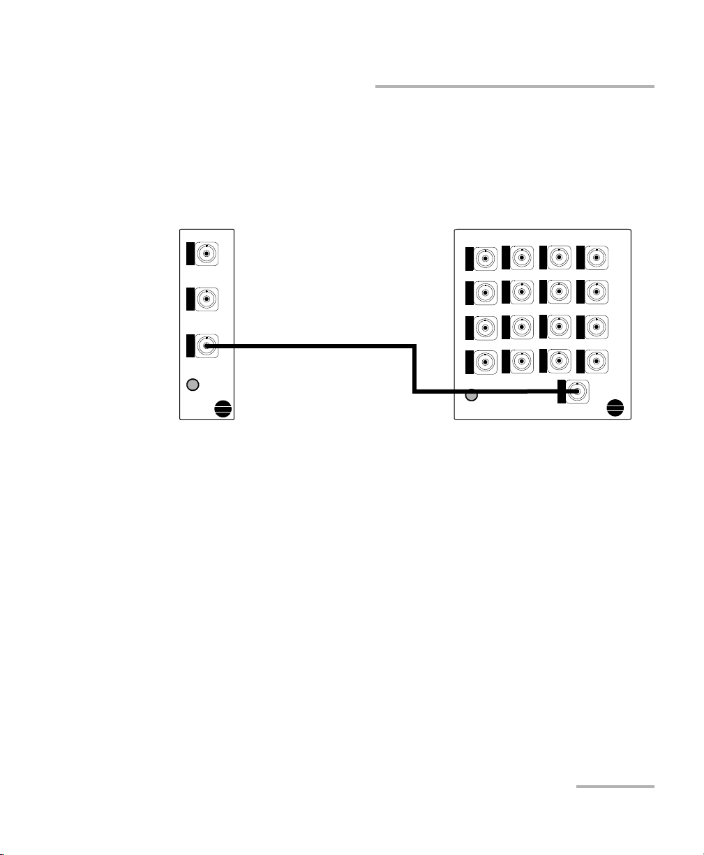
Typical Applications
Creating Customized Switch Configurations
By interconnecting two or more switch modules, customized switch
configurations can be built. For example, 1 2 and 1 16 switches can be
connected to create a 2 16 switch configuration. To do so, simply connect
the common ports of both switches.
Optical Switch 15
Page 22

Introducing the IQS-9100/9100B Optical Switch
Conventions
Conventions
Before using the product described in this guide, you should understand
the following conventions:
WARNING
Indicates a potentially hazardous situation which, if not avoided,
could result in death or serious injury. Do not proceed unless you
understand and meet the required conditions.
CAUTION
Indicates a potentially hazardous situation which, if not avoided,
may result in minor or moderate injury. Do not proceed unless you
understand and meet the required conditions.
CAUTION
Indicates a potentially hazardous situation which, if not avoided,
may result in component damage. Do not proceed unless you
understand and meet the required conditions.
IMPORTANT
Refers to information about this product you should not overlook.
The maximum input power for the IQS-9100/9100B Optical Switch
is 4 W. For more information on equipment ratings, refer to the IQS-600
Integrated Qualification System user guide.
16 IQS-9100/9100B
Page 23
2 Getting Started with Your
Optical Switch
CAUTION
Your Optical Switch contains sensitive precision optical
components. To ensure reliable, long-term service, observe proper
handling and operating instructions. At no time should the module
be subject to shock or impact.
WARNING
Do not install or terminate fibers while a light source is active.
Never look directly into a live fiber and ensure that your eyes are
protected at all times.
WARNING
The use of controls, adjustments and procedures other than those
specified herein may result in exposure to hazardous situations or
impair the protection provided by this unit.
IMPORTANT
When you see the following symbol on your unit , make sure
that you refer to the instructions provided in your user
documentation. Ensure that you understand and meet the required
conditions before using your product.
Optical Switch 17
Page 24
Getting Started with Your Optical Switch
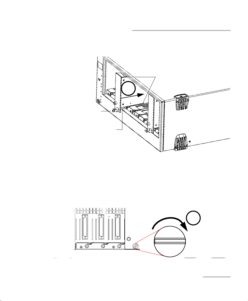
Retaining screw
knob
Protective cover
2b
2a
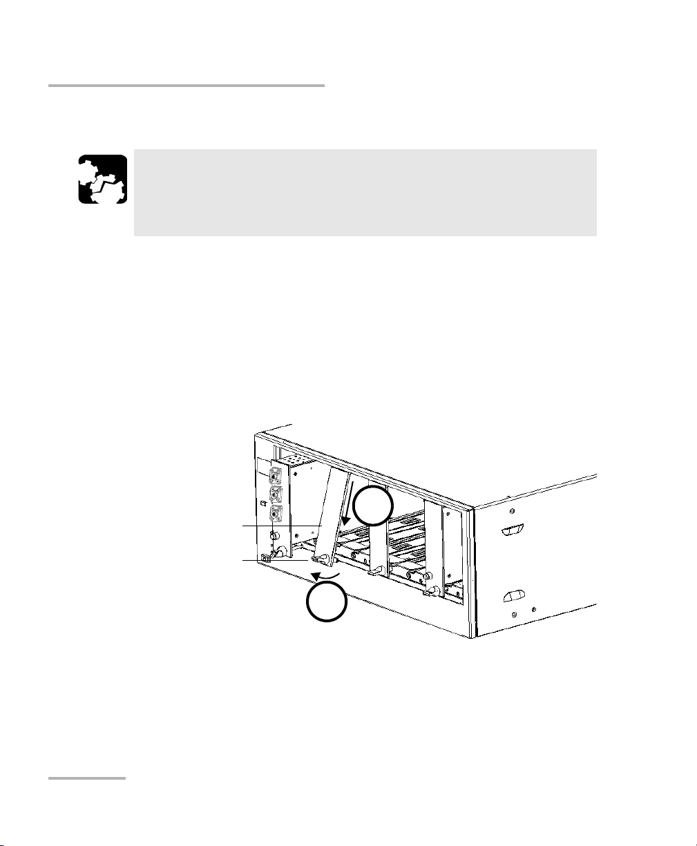
Inserting and Removing Test Modules
Inserting and Removing Test Modules
CAUTION
Never insert or remove a module while the controller unit and its
expansion units are turned on. This will result in immediate and
irreparable damage to both the module and unit.
To insert a module into the controller or expansion unit:
1. Exit IQS Manager and turn off all your units.
2. Remove the protective cover from the desired unused module slot.
2a. Pull the retaining screw knob firmly towards you and release the
bottom of the cover.
2b. Gently pull the top of the protective cover downwards, to remove
it from the unit grooves.
3. Position the module so that its front panel is facing you and the top and
bottom protruding edges are to your right.
18 IQS-9100/9100B
Page 25
Getting Started with Your Optical Switch
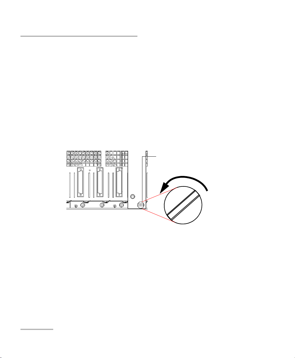
Retaining screw
Retaining screw knob
Protruding edges
(right side of module)
5
6
Inserting and Removing Test Modules
4. Insert the protruding edges of the module into the grooves of the unit’s
module slot.
5. Push the module all the way to the back of the slot, until the retaining
screw makes contact with the unit casing.
6. While applying slight pressure to the module, turn the retaining screw
knob (located at the bottom of the panel) clockwise until the knob is
horizontal.
This will secure the module into its “seated” position.
Optical Switch 19
Page 26
Getting Started with Your Optical Switch
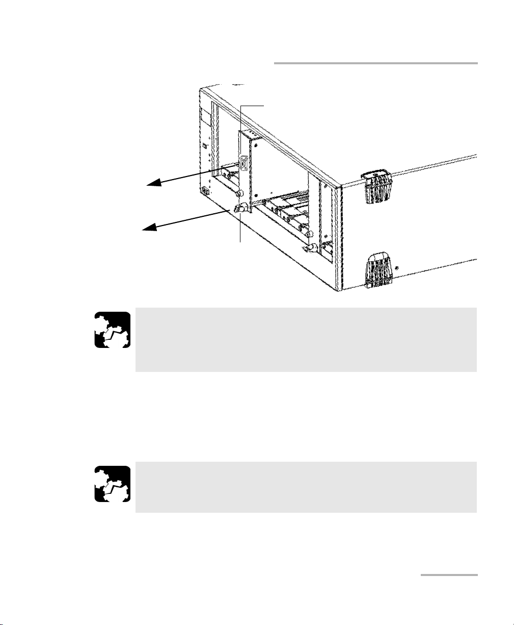
Retaining screw knob
Inserting and Removing Test Modules
The module is correctly inserted when its front panel is flush with the front
panel of the controller or expansion unit.
When you turn on the controller unit, the startup sequence will
automatically detect your module.
Note: You can insert IQ modules into your controller or expansion unit; the
IQS Manager software will recognize them. However, the IQS-9100/9100B
locking mechanism (retaining screw) will not work for IQ modules.
To remove a module from your controller or expansion unit:
1. While pulling gently on the knob, turn it counterclockwise until it stops.
The module will slowly be released from the slot.
2. Place your fingers underneath the module or hold it by the retaining
screw knob (NOT by the connector) and pull it out.
20 IQS-9100/9100B
Page 27
Getting Started with Your Optical Switch
YES
NO
Retaining screw
knob
Connector
Inserting and Removing Test Modules
CAUTION
Pulling out a module by a connector could seriously damage both
the module and connector. Always pull out a module by the
retaining screw knob.
3. Cover empty slots with the supplied protective covers.
3a. Slide the top of the protective cover into the upper grooves of the
unit.
3b. Snap the cover into place by pushing the retaining screw knob.
CAUTION
Failure to reinstall protective covers over empty slots will result in
Optical Switch 21
ventilation problems.
Page 28
Getting Started with Your Optical Switch
Starting the Optical Switch Application
Starting the Optical Switch Application
Your IQS-9100/9100B Optical Switch module can be configured and
controlled from its dedicated IQS Manager application.
Note: For details about IQS Manager, refer to the IQS platform user guide.
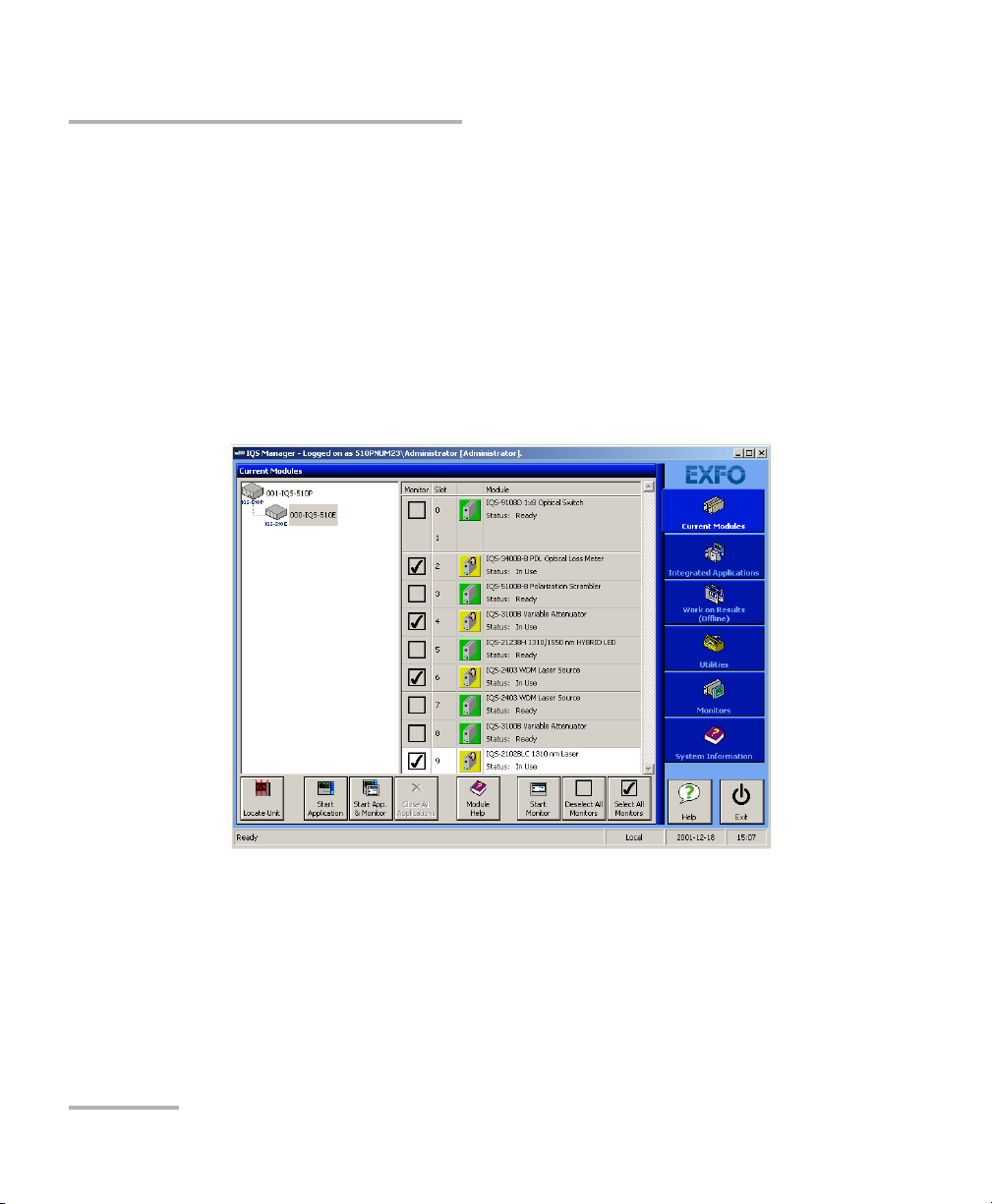
To start the application:
1. From the Current Modules function tab select the module to use.
It will turn white to indicate that it is highlighted.
2. Click Start Application.
OR
Press the green LED push button on the front of the corresponding
module.
You can also double-click its row.
22 IQS-9100/9100B
Page 29
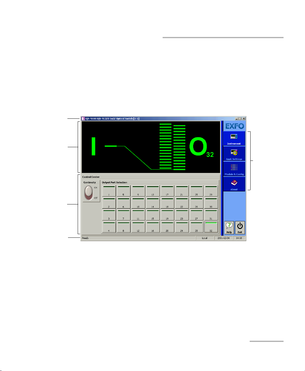
Getting Started with Your Optical Switch
Function
bar
Control
Center
Title bar
Status bar
Data
display
Starting the Optical Switch Application
Note: Pressing the LED push button will not activate or turn on the module.
Note: To start the corresponding monitor window at the same time, click Start
App. & Monitor. The window opens on the Monitors function tab.
The main window (shown below) contains all the commands required to
control the Optical Switch:
Optical Switch 23
Page 30
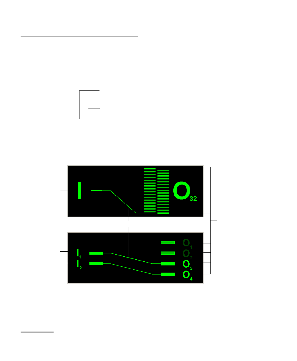
Getting Started with Your Optical Switch
Slot number in which module is inserted
(0 identifies first slot)
Controller unit or expansion unit (1 to 999) housing
the module
[999–1]
Optical signal paths
Common or
input ports
(Identified by
the letter I
and the port
number.)
Output ports
(Identified by the
letter O and the
port number.)
1 x N optical switch
2 x N optical switch
(IQS-9100 Optical Switch only)
Starting the Optical Switch Application
Title Bar
The title bar is located at the top of the main window. It displays the
module name and its position in the controller or expansion unit. The
module position is identified as follows:
Data Display
24 IQS-9100/9100B
Page 31

Getting Started with Your Optical Switch
Current date and timeModule/unit status
Local: Module controlled locally only.
Remote: Module controlled remotely, but
local commands can also be used.
Lockout: Module controlled remotely only.
Control mode
Exiting the Application
Status Bar
The status bar, located at the bottom of the main window, identifies the
operational status of the IQS-9100/9100B Optical Switch.
For more information about automating or remotely controlling the
IQS-9100/9100B Optical Switch, refer to your platform user guide.
Exiting the Application
Closing any application that is not currently being used helps freeing
system memory.
To close the application from the main window:
Click in the top right corner of the main window.
OR
Click the Exit button located at the bottom of the function bar.
To close all currently running applications:
From IQS Manager, click Close All Applications.
Optical Switch 25
Page 32

Page 33

3 Operating the Optical Switch
The IQS-9100/9100B Optical Switch comes in different models, depending
on the number of ports and switch configurations it has. To use its different
models more efficiently, follow the instructions provided in this section.
Before using the IQS-9100/9100B Optical Switch in a test setup, you must
first connect the ports to other test components and select a switching
configuration.
Note: You can configure your switch before connecting it to your test setup.
CAUTION
Your Optical Switch contains sensitive precision optical
components. To ensure reliable, long-term service, observe proper
handling and operating instructions. At no time should the module
be subject to shock or impact.
Optical Switch 27
Page 34

Operating the Optical Switch
Bare metal
(or blue border)
indicates UPC
option
Green border
indicates APC
option
2 3 4
Installing the EXFO Universal Interface (EUI)
Installing the EXFO Universal Interface (EUI)
The EUI fixed baseplate is available for connectors with angled (APC) or
non-angled (UPC) polishing. A green border around the baseplate
indicates that it is for APC-type connectors.
To install an EUI connector adapter onto the EUI baseplate:
1. Hold the EUI connector adapter so the dust cap opens downwards.
2. Close the dust cap in order to hold the connector adapter more firmly.
3. Insert the connector adapter into the baseplate.
4. While pushing firmly, turn the connector adapter clockwise on the
baseplate to lock it in place.
28 IQS-9100/9100B
Page 35

Operating the Optical Switch
Cleaning and Connecting Optical Fibers
Cleaning and Connecting Optical Fibers
IMPORTANT
To ensure maximum power and to avoid erroneous readings:
Always inspect fiber ends and make sure that they are clean as
explained below before inserting them into the port. EXFO is
not responsible for damage or errors caused by bad fiber
cleaning or handling.
Ensure that your patchcord has appropriate connectors. Joining
mismatched connectors will damage the ferrules.
To connect the fiber-optic cable to the port:
1. Inspect the fiber using a fiber inspection microscope. If the fiber is
clean, proceed to connecting it to the port. If the fiber is dirty, clean it as
explained below.
2. Clean the fiber ends as follows:
2a. Gently wipe the fiber end with a lint-free swab dipped in isopropyl
alcohol.
2b. Use compressed air to dry completely.
2c. Visually inspect the fiber end to ensure its cleanliness.
Optical Switch 29
Page 36

Operating the Optical Switch
Cleaning and Connecting Optical Fibers
3. Carefully align the connector and port to prevent the fiber end from
touching the outside of the port or rubbing against other surfaces.
If your connector features a key, ensure that it is fully fitted into the
port’s corresponding notch.
4. Push the connector in so that the fiber-optic cable is firmly in place,
thus ensuring adequate contact.
If your connector features a screwsleeve, tighten the connector
enough to firmly maintain the fiber in place. Do not overtighten, as this
will damage the fiber and the port.
Note: If your fiber-optic cable is not properly aligned and/or connected, you will
notice heavy loss and reflection.
EXFO uses good quality connectors in compliance with EIA-455-21A
standards.
To keep connectors clean and in good condition, EXFO strongly
recommends inspecting them with a fiber inspection probe before
connecting them. Failure to do so will result in permanent damage to the
connectors and degradation in measurements.
30 IQS-9100/9100B
Page 37

Operating the Optical Switch
Optimizing the Application for Repeatability
Optimizing the Application for Repeatability
The optimization for repeatability ensures better accuracy in positioning
the light path when switching.
With optimization activated, every time a switching occurs, the switch
mechanism returns to the “no continuity” (Off) position before
aligning to a new channel position. This option provides better
precision, but with slower switching.
With optimization deactivated, the switch mechanism goes directly to
the new channel position. This option provides faster switching, but
with less precision.
Note: This option is NOT available in the 1 x 2, 2 x 2 and 2 x 4 models.
To optimize switching for repeatability:
1. In the main window, select the Settings function tab.
2. Click the Optimize for Repeatability button. The light indicator on the
button will turn bright green to indicate optimization is active.
Optical Switch 31
Page 38

Operating the Optical Switch
Selecting Configurations with the 1 x n Model
Selecting Configurations with the 1 x n Model
The different configurations available in the 1 x n optical switch model
allow you to access a number of switch possibilities.
To select configurations with the 1 x n model optical switch:
1. Set the Continuity switch to the On or Off position, depending on
whether or not you want the light signal to pass through the optical
switch.
Note: For the 1 x 2 model, the Continuity function is not available in the Control
Center.
2. In the Output Port Selection panel, select the port through which you
want to direct the light.
32 IQS-9100/9100B
Page 39

Operating the Optical Switch
Selecting Configurations with the 1 x n Model
Note: You can change the output port at any time, and as many times as you
want. You cannot preset output switch port activation sequences from the
control application with 1 x n optical switches. You must activate each port
manually.
Following are some of the modules that match the 1 x n model (1 x 2, 1 x 4,
1x8 and, 1x32 models shown. 1x12, 1 x 16 and 1 x 24 models also
available).
You can also select a configuration from the QuickTools utility. For details,
see Monitoring Optical Switch Modules on page 47.
Optical Switch 33
Page 40

Operating the Optical Switch
Selecting Configurations with the 2 x 2 Model (IQS-9100 Optical Switch only)
Selecting Configurations with the 2 x 2 Model
(IQS-9100 Optical Switch only)
The 2 x 2 optical switch model offers two configurations:
Bypass mode
Insert mode
To select a configuration with the 2 x 2 optical switch model:
Click Bypass Mode or Insert Mode, according to the configuration you
want to use.
You can also select a configuration from the QuickTools utility. For details,
see Monitoring Optical Switch Modules on page 47.
Note: For the 2 x 2 model, the Continuity function is not available in the Control
Center.
34 IQS-9100/9100B
Page 41

Operating the Optical Switch
Selecting Configurations with the 2 x 4 Model (IQS-9100 Optical Switch only)
Selecting Configurations with the 2 x 4 Model
(IQS-9100 Optical Switch only)
The different configurations available with the 2 x 4 optical switch model
provides six switch possibilities.
To select a configuration with the 2 x 4 optical switch model:
In the Output Port Selection panel, click the button for the
configuration you want. For more information on 2 x 4 model
configurations, see 2 x 4 Optical Switch Module (IQS-9100 Optical
Switch only) on page 9.
You can also select a configuration from the QuickTools utility. For details,
see Monitoring Optical Switch Modules on page 47.
Optical Switch 35
Page 42

Operating the Optical Switch
To save parameters being used
just before shutting down,
overwriting the previous file.
To always use the last saved
parameters when starting.
Saving and Recalling Configurations
Saving and Recalling Configurations
Once you have set the IQS-9100/9100B Optical Switch parameters, you can
save your custom configuration and recall it at any time. You can also recall
the factory-defined settings.
Saved configurations include all parameters set in the Control Center
(Instrument function tab) and in the Settings function tab (if present).
To save a configuration:
1. Select the Configuration function tab.
2. Under Current Module Configuration, enter the name you want to
use for your configuration file.
It will be saved in
D:\Program Files\EXFO IQS Manager\AppConfig\(your_module)\.
3. Click Save.
36 IQS-9100/9100B
Page 43

Operating the Optical Switch
Saving and Recalling Configurations
To recall a configuration:
1. Select the Configuration function tab.
2. Click Open.
3. Select the configuration file you want to recall and confirm your action.
You will return to your application and the new parameters will be set.
To revert to factory settings:
1. Select the Configuration function tab.
2. Click the Reset Module to Factory Settings button.
IMPORTANT
Reverting to the factory settings will interrupt any module
operation in progress.
IMPORTANT
The operation may take a few seconds to complete.
Optical Switch 37
Page 44

Page 45

4 Controlling Multiple Optical
Switch Modules
With your platform, you can set common parameters and simultaneously
operate several modules of the same kind in a single interface, which is
particularly useful in larger systems.
Note: You should be familiar with the configuration and operation of a single
module before controlling multiple modules simultaneously.
Starting a Multimodule Application
The multimodule applications available will change according to your
module configuration (model, type, etc.).
Note: When you start a multimodule application, you cannot open a monitor
window at the same time, as it is possible with a single-module
application. You must open the monitor window independently.
To start a multimodule application:
1. In IQS Manager, select the Integrated Applications function tab.
2. Click the appropriate Multiple Module Controller button.
The multimodule application appears in a new window.
Note: More than one Multiple Module Controller button may be displayed if
different models are present in your platform.
Optical Switch 39
Page 46

Controlling Multiple Optical Switch Modules
Select or
deselect a
specific
module
Select all or
select no
modules
Selecting Modules to Control
Selecting Modules to Control
Before you can modify the module parameters, you must specify which
modules you intend to use.
To select IQS-9100/9100B Optical Switch modules:
1. On the Modules/Config function tab, select the boxes corresponding
to the modules you want to control.
OR
Click Select All if you want to work with all IQS-9100/9100B Optical
Switch modules.
2. Click Apply Selections and click the Instruments function tab.
40 IQS-9100/9100B
Page 47

Controlling Multiple Optical Switch Modules
Setting Parameters for Multiple Modules
Setting Parameters for Multiple Modules
Setting up and operating your IQS-9100/9100B Optical Switch is the same
when controlling one or many modules at the same time. For more
information, see Operating the Optical Switch on page 27.
In the multimodule application, the data display in the upper part of the
Instruments function tab provides you with useful information about the
modules.
Information is displayed in black, except when a module is stabilizing
or executing a command, in which case it is displayed in red.
The last column in the data display provides information about the
module location (unit and slot). Notice that slot numbers start at 0.
Optical Switch 41
Page 48

Controlling Multiple Optical Switch Modules
Information
on selected
modules
Control
Center
Module
selection box
Module status
indicator
Module status
Module location information
Setting Parameters for Multiple Modules
To set parameters for all selected modules:
1. Select the Instruments function tab.
2. Make sure that the check box corresponding to each module to
configure is selected.
42 IQS-9100/9100B
Page 49

Controlling Multiple Optical Switch Modules
Setting Parameters for Multiple Modules
3. Select the appropriate control.
The controls displayed in the Control Center are similar to those in the
single-module application. If one or more modules cannot execute a
command triggered by the activation of a control, an Information
window is displayed, and identifies for which modules the control is
inoperative.
For more information on using switch controls with various optical
switch models, see Operating the Optical Switch on page 27.
Optical Switch 43
Page 50

Controlling Multiple Optical Switch Modules
Selected
module in
bold or
highlighted
Control
Single
Instrument
button
Controlling a Single IQS-9100/9100B Optical Switch
Controlling a Single IQS-9100/9100B Optical
Switch
You may want to control a specific module among all the IQS-9100/9100B
Optical Switch modules that you have in the system.
To control a specific IQS-9100/9100B Optical Switch:
1. Make sure that the row corresponding to the module you want to
control appears in bold or that it is highlighted.
2. Use the Control Single Instrument button to open the IQS-9100/9100B
Optical Switch application.
44 IQS-9100/9100B
Page 51

Controlling Multiple Optical Switch Modules
IQS Manager - Integrated
Applications (Multi-modules)
Your module main application
window (single module)
Your module Multiple Module
Controller - Instruments tab
Your module Multiple Module
Controller - Modules/Config tab
Open
Apply Selections
Control Single
Instrument
Exit
Exit
Navigating and Closing Multiple Module Windows
Navigating and Closing Multiple Module
Windows
When controlling multiple modules, a number of windows are open at the
same time. To close a window, use the Exit button located under the
function tabs. You will return to the preceding window.
The following diagram illustrates the navigation between windows:
Optical Switch 45
Page 52

Page 53

5 Monitoring Optical Switch
Modules
When using your IQS-9100/9100B Optical Switch module, either alone or
with other modules in a test setup, you can view module data and status
using its monitor window in IQS Manager.
Using Monitor Windows
Monitor windows display basic data about modules. A combination of
resizable windows allows you to create an integrated data display (refer to
the platform user guide).
From the monitor window, you can change module parameters either by:
opening the module application to access all the functions
OR
using the QuickTools utility, which provides frequently used functions
from the application.
Optical Switch 47
Page 54

Monitoring Optical Switch Modules
Selected modules
(checked)
Using Monitor Windows
To select modules and display their monitor windows:
1. On the Current Modules function tab, select the controller or
expansion unit containing the modules you want to monitor.
2. In the Monitor column, select the box next to each module you want
to monitor.
If you want to monitor all the modules in the current unit, click Select
All Monitors. If you want to clear your choices, click Deselect All
Monitors.
48 IQS-9100/9100B
Page 55

Monitoring Optical Switch Modules
Rearrange
Monitors
button
(1 or 2
columns)
To r e m ov e
the monitor
Close All
button
Monitor window
arrow buttons
Using Monitor Windows
3. Click Start Monitor to apply your selection.
IQS Manager will display the selected monitor windows on the
Monitors function tab.
Note: To start th e highlighted module’s corresponding application at the same
time, click Start App. & Monitor. The application will appear in a different
window.
Optical Switch 49
Page 56

Monitoring Optical Switch Modules
Using QuickTools
Using QuickTools
With QuickTools, you can fine-tune your module directly, while keeping an
eye on your entire test setup.
Note: You can only access QuickTools if the module’s monitor window is selected
from the Monitors function tab and is currently active.
To start QuickTools:
1. From the Monitors function tab, select the monitor window of the
module you wish to control.
2. Using the arrow button in the upper left corner, select QuickTools.
The corresponding monitor window flashes when QuickTools is
activated.
Note: If you want to open the actual application for your module rather than
QuickTools, click Show Controller.
50 IQS-9100/9100B
Page 57

Monitoring Optical Switch Modules
1 x 2 and 1 x n optical switch
model QuickTools utility
2 x 2 optical switch
model QuickTools utility
(IQS-9100 Optical Switch
only)
2 x 4 optical switch model
QuickTools utility
(IQS-9100 Optical Switch
only)
Using QuickTools
For the IQS-9100/9100B Optical Switch, one of the four QuickTools utility
versions will be displayed, depending on the model of the selected
module, as shown in the figure below.
To control a specific optical switch with QuickTools:
Ensure that the switch window is selected (its title bar should be displayed
in the same color as the sidebar buttons.)
For 1 x n models, from the Output section, click the selection arrows
on both sides of the list, and then click the Check button to select
the port. For 2 x 2 or 2 x 4 models (IQS-9100 Optical Switch only), from
the 2x2 Mode or Mode 2 x 4 section, select the appropriate port
configuration (For details, see Operating the Optical Switch on
page 27).
If a Continuity switch button is displayed in the QuickTools utility, click
it to activate the optical switch (For more information, see Selecting
Configurations with the 1 x n Model on page 32).
Optical Switch 51
Page 58

Monitoring Optical Switch Modules
Using QuickTools
To c lo s e Q ui c kTo ol s :
Click the Close button located at the top of the window.
OR
Click outside the QuickTools window.
To close a monitor window:
Click the button on the upper left of the monitor window and select
Remove Monitor.
OR
Click the Close All button at the bottom of the window.
52 IQS-9100/9100B
Page 59

6 Maintenance
To help ensure long, trouble-free operation:
Always inspect fiber-optic connectors before using them and clean
them if necessary.
Keep the unit free of dust.
Clean the unit casing and front panel with a cloth slightly dampened
with water.
Store unit at room temperature in a clean and dry area. Keep the unit
out of direct sunlight.
Avoid high humidity or significant temperature fluctuations.
Avoid unnecessary shocks and vibrations.
If any liquids are spilled on or into the unit, turn off the power
immediately, disconnect from any external power source, remove the
batteries and let the unit dry completely.
The use of controls, adjustments and procedures other than those
specified herein may result in exposure to hazardous situations or
impair the protection provided by this unit.
WARNING
Optical Switch 53
Page 60

Maintenance
Cleaning Fixed Connectors
Cleaning Fixed Connectors
Regular cleaning of connectors will help maintain optimum performance.
Do not try to disassemble the unit. Doing so would break the connector.
To clean fixed connectors:
1. Fold a lint-free wiping cloth in four to form a square.
2. Moisten the center of the lint-free wiping cloth with only one drop of
isopropyl alcohol.
Alcohol may leave traces if used abundantly. Avoid contact between
the tip of the bottle and the wiping cloth, and do not use bottles
that distribute too much alcohol at a time.
3. Gently wipe the connector threads three times with the folded and
moistened section of the wiping cloth.
IMPORTANT
IMPORTANT
Isopropyl alcohol takes approximately ten seconds to evaporate.
Since isopropyl alcohol is not absolutely pure, evaporation will
leave microscopic residue. Make sure you dry the surfaces before
evaporation occurs.
4. With a dry lint-free wiping cloth, gently wipe the same surfaces three
times with a rotating movement.
5. Throw out the wiping cloths after one use.
54 IQS-9100/9100B
Page 61

Maintenance
7
8
9
Cleaning Fixed Connectors
6. Moisten a cleaning tip (2.5 mm tip) with only one drop of isopropyl
alcohol.
IMPORTANT
Alcohol may leave traces if used abundantly. Avoid contact between
the tip of the bottle and the cleaning tip, and do not use bottles
that distribute too much alcohol at a time.
7. Slowly insert the cleaning tip into the connector until it reaches the
ferrule inside (a slow clockwise rotating movement may help).
8. Gently turn the cleaning tip one full turn.
9. Continue to turn as you withdraw the cleaning tip.
10. Repeat steps 7 to 9, but this time with a dry cleaning tip (2.5 mm tip
provided by EXFO).
Note: Make sure you don’t touch the soft end of the cleaning tip and verify the
cleanliness of the cotton tip.
11. Throw out the cleaning tips after one use.
Optical Switch 55
Page 62

Maintenance
Push
Tur n
Pull
3
4
5
Cleaning EUI Connectors
Cleaning EUI Connectors
Regular cleaning of EUI connectors will help maintain optimum
performance. There is no need to disassemble the unit.
If any damage occurs to internal connectors, the module casing will
have to be opened and a new calibration will be required.
To clean EUI connectors:
1. Remove the EUI from the instrument to expose the connector
baseplate and ferrule.
IMPORTANT
2. Moisten a 2.5 mm cleaning tip with one drop of isopropyl alcohol
(alcohol may leave traces if used abundantly).
3. Slowly insert the cleaning tip into the EUI adapter until it comes out on
the other side (a slow clockwise rotating movement may help).
4. Gently turn the cleaning tip one full turn, then continue to turn as you
withdraw it.
56 IQS-9100/9100B
Page 63

Cleaning EUI Connectors
5. Repeat steps 3 to 4 with a dry cleaning tip.
Note: Make sure you don’t touch the soft end of the cleaning tip.
6. Clean the ferrule in the connector port as follows:
6a. Deposit one drop of isopropyl alcohol on a lint-free wiping cloth.
IMPORTANT
Isopropyl alcohol may leave residues if used abundantly or left to
evaporate (about 10 seconds).
Avoid contact between the tip of the bottle and the wiping cloth,
and dry the surface quickly.
6b. Gently wipe the connector and ferrule.
6c. With a dry lint-free wiping cloth, gently wipe the same surfaces to
ensure that the connector and ferrule are perfectly dry.
6d. Verify connector surface with a portable fiber-optic microscope
(for example, EXFO’s FOMS) or fiber inspection probe (for
example, EXFO’s FIP).
Maintenance
WARNING
Verifying the surface of the connector WHILE THE UNIT IS ACTIVE
WILL result in permanent eye damage.
7. Put the EUI back onto the instrument (push and turn clockwise).
8. Throw out cleaning tips and wiping cloths after one use.
Optical Switch 57
Page 64

Maintenance
Recycling and Disposal (Applies to European Union Only)
Recycling and Disposal
(Applies to European Union Only)
For complete recycling/disposal information as per European Directive
WEEE 2002/96/EC, visit the EXFO Web site at www.exfo.com/recycle.
58 IQS-9100/9100B
Page 65

7 Troubleshooting
Solving Common Problems
Problem Possible cause Recommended action
LED push button does not
light up.
Pushing the LED push
button does not open the
module main window.
Impossible to open a
window.
Insertion loss higher than
expected.
Poor repeatability. Optical source is
Power not on. Check AC power cord and
Module is not properly
inserted.
Computer is locked
up.
LED is burnt. Call EXFO.
Computer is locked
up.
Too many windows
are open at the same
time.
Dirty optical
connectors.
Improper wavelength
selected on other
instruments
unstable.
turn on the unit.
Turn off the unit, then
remove and reinsert the
module.
Reboot the unit.
Reboot the unit.
Close unused windows,
then try to reopen the
window.
Clean all optical
connectors.
Switch to the correct
wavelength on all
instruments being used.
Wait for source to stabilize.
— Select Optimize for
Repeatability.
No optical continuity. Switch is off. Set the Continuity switch
to On.
Optical Switch 59
Page 66

Troubleshooting
Obtaining Online Help
Obtaining Online Help
An online version of the IQS-9100/9100B Optical Switch user guide is
conveniently available at all times from the application.
Note: You will also find a printable PDF version on your installation DVD.
To access online help:
Click the Help button on the function bar.
60 IQS-9100/9100B
Page 67

Troubleshooting
Contacting the Technical Support Group
Contacting the Technical Support Group
To obtain after-sales service or technical support for this product, contact
EXFO at one of the following numbers. The Technical Support Group is
available to take your calls from Monday to Friday, 8:00 a.m. to 7:00 p.m.
(Eastern Time in North America).
For detailed information about technical support, visit the EXFO Web site at
www.exfo.com.
Technical Support Group
400 Godin Avenue
Quebec (Quebec) G1M 2K2
CANADA
To accelerate the process, please have information such as the name and
the serial number (see the product identification label), as well as a
description of your problem, close at hand.
1 866 683-0155 (USA and Canada)
Tel.: 1 418 683-5498
Fax: 1 418 683-9224
support@exfo.com
Optical Switch 61
Page 68

Troubleshooting
Transportation
You may also be requested to provide software and module version
numbers. This information, as well as technical support contact
information, can be found in the About function tab.
Select the Technical Support tab to view phone numbers and active
Select the Module Information tab to view the module identification,
Internet links to EXFO’s Technical Support Group. Use these links to
send an information request by e-mail or to access EXFO’s web site.
serial number and firmware version.
Transportation
Maintain a temperature range within specifications when transporting the
unit. Transportation damage can occur from improper handling. The
following steps are recommended to minimize the possibility of damage:
Pack the unit in its original packing material when shipping.
Avoid high humidity or large temperature fluctuations.
Keep the unit out of direct sunlight.
Avoid unnecessary shocks and vibrations.
62 IQS-9100/9100B
Page 69

8 Warranty
General Information
EXFO Inc. (EXFO) warrants this equipment against defects in material and
workmanship for a period of two years from the date of original shipment.
EXFO also warrants that this equipment will meet applicable specifications
under normal use.
During the warranty period, EXFO will, at its discretion, repair, replace,
or issue credit for any defective product, as well as verify and adjust the
product free of charge should the equipment need to be repaired or if the
original calibration is erroneous. If the equipment is sent back for
verification of calibration during the warranty period and found to meet all
published specifications, EXFO will charge standard calibration fees.
THIS WARRANTY IS IN LIEU OF ALL OTHER WARRANTIES EXPRESSED,
IMPLIED, OR STATUTORY, INCLUDING, BUT NOT LIMITED TO, THE
IMPLIED WARRANTIES OF MERCHANTABILITY AND FITNESS FOR A
PARTICULAR PURPOSE. IN NO EVENT SHALL EXFO BE LIABLE FOR
SPECIAL, INCIDENTAL, OR CONSEQUENTIAL DAMAGES.
Liability
EXFO shall not be liable for damages resulting from the use of the product,
nor shall be responsible for any failure in the performance of other items to
which the product is connected or the operation of any system of which
the product may be a part.
EXFO shall not be liable for damages resulting from improper usage or
unauthorized modification of the product, its accompanying accessories
and software.
Optical Switch 63
Page 70

Warranty
Exclusions
Exclusions
EXFO reserves the right to make changes in the design or construction of
any of its products at any time without incurring obligation to make any
changes whatsoever on units purchased. Accessories, including but not
limited to fuses, pilot lamps, batteries and universal interfaces (EUI) used
with EXFO products are not covered by this warranty.
This warranty excludes failure resulting from: improper use or installation,
normal wear and tear, accident, abuse, neglect, fire, water, lightning or
other acts of nature, causes external to the product or other factors beyond
the control of EXFO.
Certification
EXFO certifies that this equipment met its published specifications at the
time of shipment from the factory.
64 IQS-9100/9100B
Page 71

Warranty
Service and Repairs
Service and Repairs
EXFO commits to providing product service and repair for five years
following the date of purchase.
To send any equipment for service or repair:
1. Call one of EXFO’s authorized service centers (see EXFO Service
Centers Worldwide on page 66). Support personnel will determine if
the equipment requires service, repair, or calibration.
2. If equipment must be returned to EXFO or an authorized service
center, support personnel will issue a Return Merchandise
Authorization (RMA) number and provide an address for return.
3. If possible, back up your data before sending the unit for repair.
4. Pack the equipment in its original shipping material. Be sure to include
a statement or report fully detailing the defect and the conditions under
which it was observed.
5. Return the equipment, prepaid, to the address given to you by support
personnel. Be sure to write the RMA number on the shipping slip. EXFO
will refuse and return any package that does not bear an RMA number.
Note: A test setup fee will apply to any returned unit that, after test, is found to
meet the applicable specifications.
After repair, the equipment will be returned with a repair report. If the
equipment is not under warranty, you will be invoiced for the cost
appearing on this report. EXFO will pay return-to-customer shipping costs
for equipment under warranty. Shipping insurance is at your expense.
Routine recalibration is not included in any of the warranty plans. Since
calibrations/verifications are not covered by the basic or extended
warranties, you may elect to purchase FlexCare Calibration/Verification
Packages for a definite period of time. Contact an authorized service center
(see EXFO Service Centers Worldwide on page 66).
Optical Switch 65
Page 72

Warranty
EXFO Service Centers Worldwide
EXFO Service Centers Worldwide
If your product requires servicing, contact your nearest authorized service
center.
EXFO Headquarters Service Center
400 Godin Avenue
Quebec (Quebec) G1M 2K2
CANADA
EXFO Europe Service Center
Omega Enterprise Park, Electron Way
Chandlers Ford, Hampshire S053 4SE
ENGLAND
EXFO Telecom Equipment
(Shenzhen) Ltd.
3rd Floor, Building 10,
Yu Sheng Industrial Park (Gu Shu
Crossing), No. 467,
National Highway 107,
Xixiang, Bao An District,
Shenzhen, China, 518126
1 866 683-0155 (USA and Canada)
Tel.: 1 418 683-5498
Fax: 1 418 683-9224
support@exfo.com
Tel.: +44 2380 246810
Fax: +44 2380 246801
support.europe@exfo.com
Tel: +86 (755) 2955 3100
Fax: +86 (755) 2955 3101
support.asia@exfo.com
66 IQS-9100/9100B
Page 73

A Technical Specifications
SPECIFICATIONS
a
Switch 1 x 2, 1 x 4 1 x 8 1 x 12 1 x 16 1 x 24, 1 x 32
Operating wavelength (nm) 1290 to 1650
Insertion loss (dB) at 1310 nm
b, c
0.9 1.2 1.6 1.8 2.0
Insertion loss (dB) at 1530 nm to 1650 nm
b, c
0.7 1.0 1.2 1.4 1.5
Repeatability (dB)
d
0.02
Backreflection (dB)
(typical)
–50 (–55)
Crosstalk (dB) (typical) 50 (60)
Polarization-dependent loss (dB) (typical)
e
0.09 (0.06) 0.11 (0.08)
Switching time (ms)
c
20 30
Fiber type Singlemode 9/125 μm
Input power (damage threshold) (dBm) 27
Notes
a. Specifications valid at 23 °C ± 5 °C.
b. Insertion losss per module, including one connector.
c. Typical specifications.
d. Repeatability values are for 100 cycles per switch module at constant temperature with stabilized source/meter.
e. At 1550 nm.
f. 1 x 12 switches with EUI connectors use three slots.
GENERAL SPECIFICATIONS
Switch 1 x 2, 1 x 4 1 x 8 1 x 12 1 x 16 1 x 24, 1 x 32
Number of slots 1 2 2
f
35
Dimensions Width
Height
Depth
3.6 cm (1
7
⁄16 in)
12.5 cm (4
15
⁄
16
in)
28.2 cm (11
1
⁄8 in)
7.4 cm (2
15
⁄16 in)
12.5 cm (4
15
⁄
16
in)
28.2 cm (11
1
⁄8 in)
7.4 cm (2
15
⁄16 in)
12.5 cm (4
15
⁄
16
in)
28.2 cm (11
1
⁄8 in)
11.2 cm (4
7
⁄16 in)
12.5 cm (4
15
⁄16 in)
28.2 cm (11
1
⁄8 in)
18.8 cm (7
7
⁄16 in)
12.5 cm (4
15
⁄16 in)
28.2 cm (11
1
⁄8 in)
Weight 0.8 kg (1.1 lb) 0.8 kg (1.8 lb) 1.1 kg (2.2 lb) 1.1 kg (2.2 lb) 1.8 kg (3.9 lb)
Switch life 1 billion (10
9
) cycles minimum
Temperature operating
storage
0 °C to 40 °C (32 °F to 104 °F)
—40 °C to 70 °C (—40 °F to 158 °F)
Maximum relative humidity 80 % non-condensing at 40 °C
Instrument Drivers
LabVIEW™ drivers, SCPI commands and COM/DCOM libraries.
Remote Control
With IQS-600: GPIB (IEEE-488.1, IEEE-488.2) Ethernet and RS-232.
Standard Accessories
User guide, certificate of compliance and calibration certificate.
IMPORTANT
The following technical specifications can change without notice.
The information presented in this section is provided as a reference
only. To obtain this product’s most recent technical specifications,
visit the EXFO Web site at www.exfo.com.
Optical Switch 67
Page 74

Page 75

B SCPI Command Reference
IQS controller or expansion unit
identification number (for example, 001)
Instrument slot number (0 to 9)
XXXY
This appendix presents detailed information on the commands and
queries supplied with your IQS-9100/9100B Optical Switch.
IMPORTANT
Since the IQS controllers and expansion units can house many
instruments, you must explicitly specify which instrument you want
to remotely control.
You must add the following mnemonic at the beginning of any
command or query that you send to an instrument:
LINStrument<LogicalInstrumentPos>:
where <LogicalInstrumentPos> corresponds to the identification
number of the instrument.
For information on modifying unit identification, refer to your
platform user guide.
Optical Switch 69
Page 76

SCPI Command Reference
Quick Reference Command Tree
Quick Reference Command Tree
Command Param eter (s) P.
ROUTe[1..n] CLOSe 71
OPEN 72
STATe? 73
PAT H CATa lo g? 74
SCAN <Position> 75
SCAN? 77
SCAN ADJust 79
AUTO <AutoAdjust> 80
AUTO? 82
NEXT 84
PREV 85
SYNChronous <Synchronous> 86
SYNChronous? 87
SNUMber? 88
STATus? 89
70 IQS-9100/9100B
Page 77

SCPI Command Reference
Product-Specific Commands—Description
Product-Specific Commands—Description
:ROUTe[1..n]:CLOSe
Description This command positions the optical switch to the
reset position. In this position, there is no optical
continuity.
*RST has no effect on this command.
Syntax :ROUTe[1..n]:CLOSe
Parameter(s) None
Example(s) ROUT:CLOSE
Notes For all switches except: 1x2, 2x2, and 2x4.
See Also ROUTe[1..n]:OPEN
ROUTe[1..n]:OPEN:STATe?
Optical Switch 71
Page 78

SCPI Command Reference
Product-Specific Commands—Description
Description This command makes the switch change from
Syntax :ROUTe[1..n]:OPEN
Parameter(s) None
Example(s) ROUT:OPEN
Notes For all switches except: 1x2, 2x2, and 2x4.
See Also ROUTe[1..n]:OPEN
:ROUTe[1..n]:OPEN
the reset position (no optical continuity) to the
channel position in effect when the switch was
turned off.
*RST has no effect on this command.
ROUTe[1..n]:OPEN:STATe?
72 IQS-9100/9100B
Page 79

SCPI Command Reference
Product-Specific Commands—Description
:ROUTe[1..n]:OPEN:STATe?
Description This query returns a value indicating whether the
switch is optically open or closed.
On *RST, the value of this setting is OFF.
Syntax :ROUTe[1..n]:OPEN:STATe?
Parameter(s) None
Response Syntax <OpticalContinuity>
Response(s) OpticalContinuity:
The response data syntax for
<OpticalContinuity> is defined as a <NR1
NUMERIC RESPONSE DATA> element.
The <OpticalContinuity> response represents
the optical continuity state, where:
0, means there is no optical continuity.
1, means there is optical continuity.
Example(s) ROUT:CLOS
ROUT:OPEN:STAT? returns 0 (there is no optical
continuity)
ROUT:OPEN
ROUT:OPEN:STAT? returns 1 (there is optical
continuity)
Notes For all switches except: 1x2, 2x2, and 2x4.
See Also ROUTe[1..n]:OPEN
ROUTe[1..n]:CLOSe
Optical Switch 73
Page 80

SCPI Command Reference
Product-Specific Commands—Description
Description This query returns a value indicating the type of
Syntax :ROUTe[1..n]:PATH:CATalog?
Parameter(s) None
Response Syntax <Type>
Response(s) Type:
:ROUTe[1..n]:PATH:CATalog?
switch in use (e.g. 1x2, 1x4, 1x12, 1x16, 1x 32, 2x2
or 2x4).
*RST has no effect on this command.
The response data syntax for <Type> is defined
as a <STRING RESPONSE DATA> element.
The <Type> response is a string indicating the
switch type in the format 9x99.
Example(s) ROUT:PATH:CAT? returns "2x2"
74 IQS-9100/9100B
Page 81

SCPI Command Reference
Product-Specific Commands—Description
:ROUTe[1..n]:SCAN
Description This command sets the switch to a specific
channel.
On *RST, the selected output channel depends
on the switch configuration:
a) For 1xN switch configuration: Output 1.
b) For 2x4 switch configuration: no continuity for
both Input 1 and Input 2.
c) For 2x2 switch configuration: BYPASS state.
Syntax :ROUTe[1..n]:SCAN<wsp><Position>
Parameter(s) Position:
The program data syntax for <Position> is
defined as a <DECIMAL NUMERIC PROGRAM
DATA> element.
The <Position> is a number from 0 to 32,
depending on switch configuration as follows:
a) For a 1xN switch configuration, a number from
1 to 32, depending on the number of output
channels.
b) For a 2x4 switch, a number from 0 to 5, where
0, means no continuity for both Input 1 and
Input 2.
1, means no continuity for Input 1, and Input 2
is connected to Output 1.
Optical Switch 75
Page 82

SCPI Command Reference
Product-Specific Commands—Description
Example(s) ROUT:SCAN 1
See Also ROUTe[1..n]:SCAN?
:ROUTe[1..n]:SCAN
2, means Input 1 is connected to Output 1 and
Input 2 is connected to Output 2.
3, means Input 1 is connected to Output 2 and
Input 2 is connected to Output 3.
4, means Input 1 is connected to Output 3 and
Input 2 is connected to Output 4.
5, means Input 1 is connected to Output 4 and
Input 2 has no continuity.
c) For a 2x2 switch, a number, 1 or 2, where:
1, means BYPASS state.
2, means INSERT state.
ROUT:SCAN? returns 1
ROUT:SCAN 2
ROUT:SCAN? returns 2
ROUTe[1..n]:SCAN:PREV
ROUTe[1..n]:SCAN:NEXT
76 IQS-9100/9100B
Page 83

SCPI Command Reference
Product-Specific Commands—Description
:ROUTe[1..n]:SCAN?
Description This query returns a value indicating the current
switch position.
On *RST, the selected output channel depends
on the switch configuration:
a) For 1xN switch configuration: Output 1.
b) For 2x4 switch configuration: no continuity for
both Input 1 and Input 2.
c) For 2x2 switch configuration: BYPASS state.
Syntax :ROUTe[1..n]:SCAN?
Parameter(s) None
Response Syntax <Position>
Response(s) Position:
The response data syntax for <Position> is
defined as a <NR1 NUMERIC RESPONSE DATA>
element.
The <Position> response represents the
currently selected channel on the switch, as
follows:
a) For a 1xN switch configuration, a number from
1 to 32, depending on the number of output
channels.
b) For a 2x4 switch, a number from 0 to 5, where
0, means no continuity for both Input 1 and
Input 2.
1, means no continuity for Input 1, and Input 2
is connected to Output 1.
Optical Switch 77
Page 84

SCPI Command Reference
Product-Specific Commands—Description
Example(s) ROUT:SCAN 1
See Also ROUTe[1..n]:SCAN
:ROUTe[1..n]:SCAN?
2, means Input 1 is connected to Output 1 and
Input 2 is connected to Output 2.
3, means Input 1 is connected to Output 2 and
Input 2 is connected to Output 3.
4, means Input 1 is connected to Output 3 and
Input 2 is connected to Output 4.
5, means Input 1 is connected to Output 4 and
Input 2 has no continuity.
c) For a 2x2 switch, a number, 1 or 2, where:
1, means BYPASS state.
2, means INSERT state.
ROUT:SCAN? returns 1
ROUT:SCAN 2
ROUT:SCAN? returns 2
ROUTe[1..n]:SCAN:PREV
ROUTe[1..n]:SCAN:NEXT
78 IQS-9100/9100B
Page 85

SCPI Command Reference
Product-Specific Commands—Description
:ROUTe[1..n]:SCAN:ADJust
Description This command makes the switch mechanism
return to a reference position before aligning to
the current position.
This command is an event and has no associated
*RST condition or query form.
Syntax :ROUTe[1..n]:SCAN:ADJust
Parameter(s) None
Example(s) ROUT:SCAN:ADJ
See Also ROUTe[1..n]:SCAN:ADJust:AUTO
ROUTe[1..n]:SCAN:ADJust:AUTO?
Optical Switch 79
Page 86

SCPI Command Reference
Product-Specific Commands—Description
Description This command sets the <Optimize for
Syntax :ROUTe[1..n]:SCAN:ADJust:AUTO<wsp><Auto
Parameter(s) AutoAdjust:
:ROUTe[1..n]:SCAN:ADJust:AUTO
repeatability> option. When this option is
selected, the switch mechanism returns to a
reference position before aligning to a new
position. This ensures optimum repeatability.
When this option is not selected, the switch
mechanism goes directly to the new channel
position. This provides faster switching times, but
less repeatability.
On *RST, the value of this setting is OFF.
Adjust>
The program data syntax for <AutoAdjust> is
defined as a <Boolean Program Data> element.
The <AutoAdjust> special forms ON and OFF
are accepted on input for increased readability.
ON corresponds to 1 and OFF corresponds to 0.
The <AutoAdjust> parameter enables or
disables the optimization for repeatability.
1 or ON, enables the optimization for
repeatability.
0 or OFF, disables the optimization for
repeatability.
80 IQS-9100/9100B
Page 87

SCPI Command Reference
Product-Specific Commands—Description
:ROUTe[1..n]:SCAN:ADJust:AUTO
Example(s) ROUT:SCAN:ADJ:AUTO 0
ROUT:SCAN:ADJ:AUTO? returns 0 (optimization
for repeatability is not selected).
ROUT:SCAN:ADJ:AUTO 1
ROUT:SCAN:ADJ:AUTO? returns 1 (optimization
for repeatability is selected).
Notes For all switches except: 1x2 and 2x2.
See Also ROUTe[1..n]:SCAN:ADJust
ROUTe[1..n]:SCAN:ADJust:AUTO?
Optical Switch 81
Page 88

SCPI Command Reference
Product-Specific Commands—Description
Description This query returns the current value of the
Syntax :ROUTe[1..n]:SCAN:ADJust:AUTO?
Parameter(s) None
Response Syntax <AutoAdjust>
Response(s) AutoAdjust:
:ROUTe[1..n]:SCAN:ADJust:AUTO?
<Optimize for repeatability> option. When this
option is selected, the switch mechanism returns
to a reference position before aligning to a new
position. This ensures optimum repeatability.
When this option is not selected, the switch
mechanism goes directly to the new channel
position. This provides faster switching times, but
less repeatability.
On *RST, the value of this setting is OFF.
The response data syntax for <AutoAdjust> is
defined as a <NR1 NUMERIC RESPONSE DATA>
element.
82 IQS-9100/9100B
Page 89

SCPI Command Reference
Product-Specific Commands—Description
:ROUTe[1..n]:SCAN:ADJust:AUTO?
The <AutoAdjust> response represents the
current state of the <Optimize for repeatability>
option, where:
1, <Optimize for repeatability> option is
selected.
0, <Optimize for repeatability> option is not
selected.
Example(s) ROUT:SCAN:ADJ:AUTO 0
ROUT:SCAN:ADJ:AUTO? returns 0 (optimization
for repeatability is not selected).
ROUT:SCAN:ADJ:AUTO 1
ROUT:SCAN:ADJ:AUTO? returns 1 (optimization
for repeatability is selected).
See Also ROUTe[1..n]:SCAN:ADJust
ROUTe[1..n]:SCAN:ADJust:AUTO
Optical Switch 83
Page 90

SCPI Command Reference
Product-Specific Commands—Description
Description This command moves the switch to the next
Syntax :ROUTe[1..n]:SCAN:NEXT
Parameter(s) None
Example(s) ROUT:SCAN 1
See Also ROUTe[1..n]:SCAN
:ROUTe[1..n]:SCAN:NEXT
position.
This command is an event and has no associated
*RST condition or query form.
ROUT:SCAN:NEXT
ROUT:SCAN? returns 2
ROUTe[1..n]:SCAN?
ROUTe[1..n]:SCAN:PREV
84 IQS-9100/9100B
Page 91

SCPI Command Reference
Product-Specific Commands—Description
:ROUTe[1..n]:SCAN:PREV
Description This command moves the switch to its previous
position.
This command is an event and has no associated
*RST condition or query form.
Syntax :ROUTe[1..n]:SCAN:PREV
Parameter(s) None
Example(s) ROUT:SCAN 2
ROUT:SCAN:PREV
ROUT:SCAN? returns 1
See Also ROUTe[1..n]:SCAN
ROUTe[1..n]:SCAN?
ROUTe[1..n]:SCAN:NEXT
Optical Switch 85
Page 92

SCPI Command Reference
Product-Specific Commands—Description
Description This command enables/disables the switch to
Syntax :ROUTe[1..n]:SCAN:SYNChronous<wsp><Sync
Parameter(s) Synchronous:
:ROUTe[1..n]:SCAN:SYNChronous
change position synchronously or not.
hronous>
The program data syntax for <Synchronous> is
defined as a <Boolean Program Data> element.
The <Synchronous> special forms ON and OFF
are accepted on input for increased readability.
ON corresponds to 1 and OFF corresponds to 0.
The <Synchronous> parameter enables or
disables the synchronous mode.
1 or ON, enables the synchronous mode for
changing position.
0 or OFF, disables the synchronous mode for
changing position.
Example(s) ROUT:SCAN:SYNC 0
ROUT:SCAN:SYNC? returns 0
ROUT:SCAN 12
STATUS? returns BUSY (Module busy)
See Also ROUTe[1..n]:SCAN
ROUTe[1..n]:SCAN?
ROUTe[1..n]:SCAN:SYNChronous?
86 IQS-9100/9100B
Page 93

SCPI Command Reference
Product-Specific Commands—Description
:ROUTe[1..n]:SCAN:SYNChronous?
Description This query returns a value indicating whether the
switch is changing position synchronously or not.
On *RST, the value of this setting is ON.
Syntax :ROUTe[1..n]:SCAN:SYNChronous?
Parameter(s) None
Response Syntax <Synchronous>
Response(s) Synchronous:
The response data syntax for <Synchronous> is
defined as a <NR1 NUMERIC RESPONSE DATA>
element.
The <Synchronous> response represents
switching position mode, where:
0, means the module is changing position
asynchronously.
1, means the module is changing position
synchronously.
See Also ROUTe[1..n]:SCAN
ROUTe[1..n]:SCAN?
ROUTe[1..n]:SCAN:SYNChronous
Optical Switch 87
Page 94

SCPI Command Reference
Product-Specific Commands—Description
Description This query returns a value indicating the
Syntax :SNUMber?
Parameter(s) None
Response Syntax <SerialNumber>
Response(s) SerialNumber:
:SNUMber?
module's serial number
This command is an event and has no associated
*RST condition or query form.
The response data syntax for <SerialNumber> is
defined as a <STRING RESPONSE DATA>
element.
The <SerialNumber> response represents a
string containing the modules serial number.
Example(s) SNUM? returns "123456-AB"
88 IQS-9100/9100B
Page 95

SCPI Command Reference
Product-Specific Commands—Description
:STATus?
Description This query returns a value indicating the status of
the switch (READY, BUSY, etc.)
This command is an event and has no associated
*RST condition or query form.
Syntax :STATus?
Parameter(s) None
Response Syntax <Status>
Response(s) Status:
The response data syntax for <Status> is defined
as a <CHARACTER RESPONSE DATA> element.
The <Status> response represents the module
state, where:
UNINITIALIZED, means the module is not
initialized.
INITINPROGRESS, means the module
initialization is in progress,
READY, means the module is ready,
BUSY, means the module is busy,
DISCONNECTED, means the module is
disconnected,
DEFECTIVE, means the module is defective, and
UNCONFIGURED, means the module is not
configured.
Example(s) STAT? returns READY (Module is ready.)
Optical Switch 89
Page 96

Page 97

Index
Index
A
About function tab ..................................... 48
after-sales service ........................................ 47
application
contacting EXFO support from .............. 48
exiting ................................................... 25
main window description ...................... 23
setting up .............................................. 27
starting, single-module.......................... 22
see also optical switch
B
bidirectional optical switch ......................... 10
building optical switch configurations ........ 15
Busy, module status .................................... 25
bypass
light path, 2 x 2 optical switch .............. 10
state, 2 x 2 optical switch ...................... 10
C
caution
of personal hazard................................. 16
of product hazard.................................. 16
certification information ................................v
channel. see light path
cleaning
EUI connectors....................................... 42
fiber ends .............................................. 29
fixed connectors .................................... 40
front panel............................................. 39
common port .............................................. 10
configuration
recall...................................................... 36
save ....................................................... 36
configurations, optical switch
1 x n model............................................ 32
2 x 2 model............................................ 34
2 x 4 model............................................ 35
available................................................. 32
basic principles ...................................... 10
changing................................................ 33
customized ............................................15
selecting ................................................ 32
conformity, declaration of ............................. v
connecting devices under test ..................... 12
connectors, cleaning.............................. 40, 42
contact information, EXFO ..........................48
continuity function, optical switch .............. 32
continuity, optical switch ................ 31, 33, 45
conventions, safety...................................... 16
customer service.................................... 48, 51
customized optical switch configurations.... 15
D
declaration of conformity .............................. v
devices under test, connecting .................... 12
E
equipment returns....................................... 51
EUI
baseplate ...............................................28
connector adapter ................................. 28
EUI connectors, cleaning .............................42
EXFO support e-mail.................................... 48
EXFO universal interface. see EUI
EXFO Web site ............................................. 48
exiting application....................................... 25
Optical Switch 91
Page 98

Index
F
fiber ends, cleaning..................................... 29
firmware version, module ........................... 48
front panel description, optical switch .......... 2
front panel, cleaning................................... 39
H
help. see online user guide
I
identification label ...................................... 47
identification, slot ....................................... 24
inserted
light path, 2 x 2 optical switch .............. 10
state, 2 x 2 optical switch ...................... 10
inserting a module ...................................... 18
insertion loss
higher than expected............................. 45
measuring.............................................. 13
IQS-9100 Optical Switch. see optical switch
L
label, identification ..................................... 47
LabVIEW drivers ............................................ 1
LED push button
location ................................................... 3
problem with......................................... 45
light path
bypass state, 2 x 2 optical switch .......... 10
inserted state, 2 x 2 optical switch ........ 10
M
main window, application........................... 23
maintenance
EUI connectors....................................... 42
fixed connectors .................................... 40
front panel ............................................ 39
general information............................... 39
measuring switch port insertion loss........... 13
model, optical switch
1 x n....................................................... 33
2 x 2....................................................... 34
2 x 4....................................................... 35
module
insertion................................................. 18
removal.................................................. 18
status..................................................... 25
see also optical switch
module information
firmware version number....................... 48
module identification number ...............48
serial number......................................... 48
module position .......................................... 24
mounting EUI connector adapter ................ 28
multiple devices, testing.............................. 12
O
online user guide......................................... 46
operating the optical switch........................ 27
optical continuity
function ................................................. 32
optimization for repeatability ................31
problem with ......................................... 45
optical switch
available models .................................. 1, 2
bidirectional........................................... 10
connecting optical fiber ......................... 27
custom configurations ........................... 15
front panel............................................... 2
introducing .............................................. 1
operating ............................................... 27
optimizing for repeatability ................... 31
ports ...................................................... 10
see also application and module
optimizing switch for repeatability.............. 31
92 IQS-9100/9100B
Page 99

Index
P
path, light (2 x 2 optical switch)
bypass state........................................... 10
inserted state......................................... 10
PDF. see online user guide
poor repeatability........................................ 45
position, module ......................................... 24
product
identification label................................. 47
specifications......................................... 53
R
Ready, module status .................................. 25
recalling a configuration ............................. 36
remote control
methods .................................................. 1
removing a module ..................................... 18
repeatability
optimizing switch for............................. 31
problem with......................................... 45
retaining screw knob location ....................... 3
return merchandise authorization (RMA) .... 51
S
safety
caution .................................................. 16
conventions ........................................... 16
warning ................................................. 16
saving configuration ................................... 36
selecting
configurations with the 1 x n model...... 32
configurations with the 2 x 2 model...... 34
configurations with the 2 x 4 model...... 35
serial number, module ................................ 48
service and repairs....................................... 51
service centers............................................. 52
shipping to EXFO ........................................ 51
slot number................................................. 24
software. see application
specifications, product ................................ 53
state, 2 x 2 optical switch
bypass.................................................... 10
inserted.................................................. 10
status bar ....................................................25
storage requirements ..................................39
suggested applications................................ 12
switch. see optical switch
switching
accuracy................................................. 31
basic principles ...................................... 10
longer time ............................................ 31
optimized for repeatability..................... 31
symbols, safety ............................................ 16
T
technical specifications................................ 53
technical support................................... 47, 48
temperature for storage .............................. 39
testing with multiple devices....................... 12
title bar........................................................ 24
transportation requirements.................. 39, 48
U
user guide. see online user guide
W
warranty
certification............................................ 50
exclusions .............................................. 50
general................................................... 49
liability ................................................... 49
window, impossible to open .......................45
Optical Switch 93
Page 100

NOTICE
抩⛙
CHINESE REGULATION ON RESTRICTION OF HAZARDOUS SUBSTANCES
₼⦌␂ℝ☀⹂䓸德棟Ⓟ䤓屓⸩
NAMES AND CONTENTS OF THE TOXIC OR HAZARDOUS SUBSTANCES OR ELEMENTS
CONTAINED IN THIS EXFO PRODUCT
▔⚺⦷㦻 EXFO ℶ❐₼䤓㦘㹡㦘⹂䓸德㒥⏒侯䤓⚜䱿✛⚺摞
O
Indicates that this toxic or hazardous substance contained in all of the homogeneous
materials for this part is below the limit requirement in SJ/T11363-2006
嫷䯉年㦘㹡㦘⹂䓸德⦷年捷ↅ㓏㦘⧖德㧟㠨₼䤓⚺摞⧖⦷ SJ/T11363-2006 㪖屓⸩䤓
棟摞尐㻑ⅴₚᇭ
X
Indicates that this toxic or hazardous substance contained in at least one of the homogeneous
materials used for this part is above the limit requirement in SJ/T11363-2006
嫷䯉年㦘㹡㦘⹂䓸德咂⺠⦷年捷ↅ䤓㩟⧖德㧟㠨₼䤓⚺摞怔⒉ SJ/T11363-2006 㪖
屓⸩䤓棟摞尐㻑ᇭ
Part Name
捷ↅ⚜䱿
Toxic or hazardous Substances and Elements
㦘㹡㦘⹂䓸德✛⏒侯
Lead
杔
(Pb)
Mercury
㻭
(Hg)
Cadmium
椣
(Cd)
Hexavalent
Chromium
⏼ↆ杻
(Cr VI)
Pol yb ro mi na te d
biphenyls
⮩䅃勣啾
(PBB)
Polybrominated
diphenyl ethers
⮩䅃ℛ啾搩
(PBDE)
Enclosure
⮥⮂
OO O O O O
Electronic and
electrical
sub-assembly
䟄✛䟄兓ↅ
XO X O X X
Optical
sub-assembly
a
⏘ⷵ兓ↅ
a
a. If applicable.
Ⱁ㨫抑䞷ᇭ
XO O O O O
Mechanical
sub-assembly
a
㧉㬿兓ↅ
a
OO O O O O
 Loading...