

Page 1
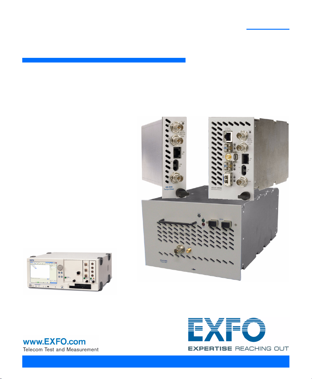
SONET/SDH Application
IQS-8100 Series for IQS-600
User Guide
Page 2

Copyright © 2007–2011 EXFO Inc. All rights reserved. No part of this
publication may be reproduced, stored in a retrieval system or transmitted
in any form, be it electronically, mechanically, or by any other means such
as photocopying, recording or otherwise, without the prior written
permission of EXFO Inc. (EXFO).
Information provided by EXFO is believed to be accurate and reliable.
However, no responsibility is assumed by EXFO for its use nor for any
infringements of patents or other rights of third parties that may result from
its use. No license is granted by implication or otherwise under any patent
rights of EXFO.
EXFO’s Commerce And Government Entities (CAGE) code under the North
Atlantic Treaty Organization (NATO) is 0L8C3.
The information contained in this publication is subject to change without
notice.
Trademarks
EXFO’s trademarks have been identified as such. However, the presence
or absence of such identification does not affect the legal status of any
trademark.
Units of Measurement
Units of measurement in this publication conform to SI standards and
practices.
September 13, 2011
Version number: 6.0.0
ii IQS-8100 Series Transport Blazer
Page 3

Contents
Contents
Certification Information ........................................................................................................x
1 Introducing the IQS-8100 Series Transport Blazer ..................................... 1
Module-Related Information ...................................................................................................4
Conventions ............................................................................................................................5
2 Safety Information ....................................................................................... 7
Laser Safety Warnings .............................................................................................................7
Installation Instruction Warnings ............................................................................................8
3 Getting Started .......................................................................................... 11
IQS Manager Installation ......................................................................................................11
Inserting and Removing Test Modules ..................................................................................11
Turning the Unit On ..............................................................................................................11
4 Physical Interfaces and LEDs ..................................................................... 13
Modules ................................................................................................................................13
Port Availability on IQS-8100 Series Module .........................................................................18
OTN/OC-N/STM-N Interface Connections ..............................................................................20
Electrical SONET/DSn/SDH/PDH Interface Connection ............................................................22
Clock Interface Connections .................................................................................................23
Ethernet 10/100/1000Base-T Interface Connection ...............................................................24
Ethernet ADD/DROP Gig-E Interface Connection ...................................................................25
DCC/GCC/UC Interface Connection .......................................................................................26
Status LED ............................................................................................................................26
5 Introducing and Using the Graphical User Interface ............................... 27
Starting the IQS-8100 Series Transport Blazer Application ....................................................27
Main Window .......................................................................................................................29
Global Test Status and Controls ............................................................................................35
Favorites ...............................................................................................................................40
Test Report Generation .........................................................................................................42
Usual Tab Elements ...............................................................................................................46
Tab Configuration .................................................................................................................49
Keyboard Usage ....................................................................................................................53
6 Creating and Starting a Test Case ............................................................. 59
Supported Paths/Mappings ...................................................................................................59
Introducing the Test Setup ....................................................................................................62
Typical Test Cases ..................................................................................................................65
SONET/SDH Application iii
Page 4

Contents
7 Smart Mode ...............................................................................................111
SmartMode Interface Description .......................................................................................112
Using SmartMode for Alarm/Error Monitoring ...................................................................115
Creating and Starting a Test Case Using SmartMode ..........................................................122
Legend ................................................................................................................................123
8 Summary Tabs ...........................................................................................125
Test Summary .....................................................................................................................125
Alarm Summary ..................................................................................................................132
Test Logger .........................................................................................................................135
9 Port Tabs ....................................................................................................137
Port TX (Electrical Interfaces) ..............................................................................................138
Port RX (Electrical Interfaces) ..............................................................................................142
Port TX (Optical Interfaces) .................................................................................................147
Port RX (Optical Interfaces) .................................................................................................150
10 OTN Tabs ....................................................................................................153
FEC TX ................................................................................................................................154
FEC RX ................................................................................................................................156
OTU TX ...............................................................................................................................157
OTU OH TX .........................................................................................................................160
OTU TTI TX ..........................................................................................................................162
OTU RX ...............................................................................................................................163
OTU OH RX .........................................................................................................................166
OTU TTI RX ..........................................................................................................................168
ODU TCM TX .......................................................................................................................170
ODU TCM TTI TX .................................................................................................................173
ODU TCM RX ......................................................................................................................175
ODU TCM TTI RX .................................................................................................................178
ODU TX ...............................................................................................................................180
ODU OH TX .........................................................................................................................182
ODU TTI/FTFL TX .................................................................................................................186
ODU RX ..............................................................................................................................189
ODU OH RX ........................................................................................................................191
ODU TTI/FTFL RX .................................................................................................................194
OPU TX ...............................................................................................................................197
OPU OH TX .........................................................................................................................200
OPU RX ...............................................................................................................................203
OPU OH RX .........................................................................................................................205
GMP TX ..............................................................................................................................208
GMP RX ..............................................................................................................................209
iv IQS-8100 Series Transport Blazer
Page 5

Contents
11 SONET Tabs ............................................................................................... 211
Section TX (SONET) .............................................................................................................213
Section RX (SONET) .............................................................................................................219
Section OH TX/RX (SONET) ..................................................................................................221
Line TX (SONET) ..................................................................................................................223
Line RX (SONET) ..................................................................................................................228
Line OH TX/RX (SONET) .......................................................................................................234
APS/Advanced Line OH TX/RX (SONET) ................................................................................236
HOP TX (SONET) ..................................................................................................................245
HOP RX (SONET) .................................................................................................................251
HOP OH TX/RX (SONET) ......................................................................................................254
Path Signal Label (C2) .........................................................................................................256
LOP TX (SONET) ..................................................................................................................257
LOP RX (SONET) ..................................................................................................................263
LOP OH TX/RX (SONET) .......................................................................................................266
12 DSn Tabs .................................................................................................... 269
DS0/64K TX .........................................................................................................................270
DS0/64K RX .........................................................................................................................273
DS1/1.5M TX .......................................................................................................................275
DS1/1.5M RX ......................................................................................................................278
FDL TX ................................................................................................................................280
FDL RX ................................................................................................................................285
FDL PRM TX ........................................................................................................................288
FDL PRM RX ........................................................................................................................290
FDL PRM Content RX ...........................................................................................................291
DS3/45M TX ........................................................................................................................293
DS3/45M RX .......................................................................................................................295
DS3 FEAC TX .......................................................................................................................297
DS3 FEAC RX .......................................................................................................................301
SONET/SDH Application v
Page 6

Contents
13 SDH Tabs ....................................................................................................303
Regenerator Section TX (SDH) .............................................................................................305
Regenerator Section RX (SDH) ............................................................................................311
Regenerator Section OH TX/RX (SDH) .................................................................................313
Multiplex Section TX (SDH) .................................................................................................315
Multiplex Section RX (SDH) .................................................................................................320
Multiplex Section OH TX/RX (SDH) ......................................................................................326
Multiplex Section APS/Advanced OH TX/RX (SDH) ...............................................................328
HOP TX (SDH) .....................................................................................................................335
HOP RX (SDH) .....................................................................................................................341
HOP OH TX/RX (SDH) ..........................................................................................................344
LOP TX (SDH) ......................................................................................................................347
LOP RX (SDH) ......................................................................................................................353
LOP OH TX/RX (SDH) ...........................................................................................................356
LOP TX (SDH, TU-3 path) .....................................................................................................358
LOP RX (SDH, TU-3 path) ....................................................................................................364
LOP OH TX/RX (SDH, TU-3 path) ..........................................................................................367
14 PDH Tabs ....................................................................................................369
E0/64K TX ...........................................................................................................................370
E0/64K RX ...........................................................................................................................373
E1/2M TX ............................................................................................................................375
E1/2M RX ............................................................................................................................378
E2/8M TX ............................................................................................................................381
E2/8M RX ............................................................................................................................383
E3/34M TX ..........................................................................................................................385
E3/34M RX ..........................................................................................................................387
E4/140M TX ........................................................................................................................389
E4/140M RX ........................................................................................................................391
15 Ethernet Tabs ............................................................................................393
Configuration .....................................................................................................................393
Error/Alarm TX ....................................................................................................................396
Error/Alarm RX ....................................................................................................................399
Statistics TX ........................................................................................................................401
Statistics RX ........................................................................................................................402
16 BERT Tabs ...................................................................................................405
Pattern TX ...........................................................................................................................405
Pattern RX ...........................................................................................................................409
vi IQS-8100 Series Transport Blazer
Page 7

Contents
17 Advanced Tabs .......................................................................................... 411
Service Disruption Time (SDT) .............................................................................................411
Service Disruption Time (SDT) - Monitor .............................................................................415
Service Disruption Time (SDT) - Results ...............................................................................421
Round Trip Delay (RTD) .......................................................................................................425
18 Next-Generation Tabs ............................................................................... 429
GFP Overview TX .................................................................................................................431
GFP Frame TX .....................................................................................................................432
GFP Channel TX ..................................................................................................................435
GFP Channel Stats TX ..........................................................................................................439
GFP OH TX ..........................................................................................................................440
GFP Client TX ......................................................................................................................444
GFP Overview RX ................................................................................................................447
GFP Frames RX ....................................................................................................................449
GFP Channel RX ..................................................................................................................451
GFP Channel Stats RX .........................................................................................................454
GFP OH RX ..........................................................................................................................455
GFP Client RX ......................................................................................................................457
VCAT TX - Overview ............................................................................................................459
VCAT TX - Diff Delay ...........................................................................................................461
VCAT RX - Overview ............................................................................................................463
VCAT RX - Diff Delay ...........................................................................................................466
LCAS - Source .....................................................................................................................468
LCAS Sink ............................................................................................................................481
19 Common Tabs ........................................................................................... 491
HOP/LOP Pointer Adjust TX (SONET/SDH) ............................................................................492
HOP/LOP Pointer Adjust RX (SONET/SDH) ............................................................................495
TCM TX ...............................................................................................................................497
TCM RX ...............................................................................................................................500
Performance Monitoring (PM) ............................................................................................504
Client Offset TX ...................................................................................................................513
Client Offset RX ..................................................................................................................515
20 System Tab ................................................................................................ 519
Clock Synchronization ........................................................................................................520
Application Preferences ......................................................................................................528
Default Test Preferences ......................................................................................................530
Module Information ...........................................................................................................544
Software Options ................................................................................................................546
Remote Control ..................................................................................................................549
SONET/SDH Application vii
Page 8

Contents
21 Tools Tab ....................................................................................................551
Script Tab ............................................................................................................................551
22 Power Failure Recovery ............................................................................555
23 Maintenance ..............................................................................................557
Recalibrating the Unit .........................................................................................................558
Recycling and Disposal (Applies to European Union Only) ..................................................559
24 Troubleshooting ........................................................................................561
Solving Common Problems .................................................................................................561
Finding Information on the EXFO Web Site ........................................................................562
Contacting the Technical Support Group ............................................................................563
Transportation ....................................................................................................................564
25 Warranty ....................................................................................................565
General Information ...........................................................................................................565
Liability ...............................................................................................................................566
Exclusions ...........................................................................................................................566
Certification ........................................................................................................................566
Service and Repairs .............................................................................................................567
EXFO Service Centers Worldwide ........................................................................................568
A Specifications ............................................................................................569
Electrical Interfaces for IQS-8105/15/20/30 .........................................................................569
Optical Interfaces ................................................................................................................570
Synchronization Interfaces for IQS-8105/15/20/30 ..............................................................572
Synchronisation Interfaces for IQS-8140 .............................................................................573
Ethernet Add/Drop Interfaces for IQS-8105/15/20/30 .........................................................573
Ethernet Interfaces .............................................................................................................574
General Specifications ........................................................................................................575
viii IQS-8100 Series Transport Blazer
Page 9

Contents
B Glossary .................................................................................................... 577
SONET/DSn/SDH/PDH Nomenclature ...................................................................................577
Signal Rates ........................................................................................................................577
SONET/SDH High and LowOrder Path Nomenclature ..........................................................578
SONET/SDH Alarms and Errors Nomenclature .....................................................................579
Acronym List .......................................................................................................................581
G.709 Optical Transport Network (OTN) .............................................................................601
SONET Numbering Convention ...........................................................................................616
SDH Numbering Convention ...............................................................................................618
SONET - Section Overhead (SOH) ........................................................................................622
SONET - Line Overhead (LOH) .............................................................................................624
SONET - Path Overhead (POH) ............................................................................................627
SONET - VT Path Overhead .................................................................................................630
SDH - Regenerator Section Overhead (RSOH) ......................................................................634
SDH - Multiplex Section Overhead (MSOH) .........................................................................636
SDH - Higher-Order Path Overhead (HP-POH) ......................................................................638
SDH - Lower-Order Path Overhead ......................................................................................641
10G Ethernet ......................................................................................................................644
Next-Gen - Generic Framing Procedure (GFP) ......................................................................647
Next-Gen - Virtual Concatenation (VCAT) ...........................................................................660
Next-Gen - Link-Capacity Adjustment Scheme (LCAS) .........................................................673
Index .............................................................................................................. 685
SONET/SDH Application ix
Page 10

Certification Information
Certification Information
Federal Communications Commission (FCC) and
Industry Canada (IC) Information
Electronic test and measurement equipment is exempt from FCC Part 15
compliance in the United States and from IC ICES 003 compliance in
Canada. However, EXFO Inc. (EXFO) makes reasonable efforts to ensure
compliance to the applicable standards.
The limits set by these standards are designed to provide reasonable
protection against harmful interference when the equipment is operated in
a commercial environment. This equipment generates, uses, and can
radiate radio frequency energy and, if not installed and used in accordance
with the user guide, may cause harmful interference to radio
communications. Operation of this equipment in a residential area is likely
to cause harmful interference in which case the user will be required to
correct the interference at his own expense.
European Union (CE) Information
Electronic test and measurement equipment is subject to the EMC
Directive in the European Union. The EN61326 standard prescribes both
emission and immunity requirements for laboratory, measurement, and
control equipment. This unit has been tested and found to comply with the
limits for a Class A digital device. Please refer to the CE Declaration of
Conformity on page xii.
x IQS-8100 Series Transport Blazer
Page 11

Certification Information
For continued compliance to the requirements of the EMC
Directive:
1. Fo r th e BNC/AUX port(s) use double-shielded coaxial cable, type 734A
or equivalent.
2. Fo r th e REF OUT port use double shielded cable, type LMR-240
ULTRAFLEX or equivalent, with a maximum length of 3m for
IQS-8105/15/20/30 and 1m for IQS-8140.
3. Fo r th e DCC/GCC/UC port use shielded cable, type Molex 83421 or
equivalent, with a maximum length of 3m.
Note: If the equipment described herein bears the CE symbol, the said equipment
complies with the applicable European Union Directive and Standards
mentioned in the Declaration of Conformity.
Laser
For all models at the exception of the IQS-8140:
This product complies with 21 CFR 1040.10 and with EN 60825-1.
This product may employ a Class 1 or Class 1M laser SFP or XFP. The laser
classification is reproduced on the SFP/XFP.
For the IQS-8140:
Class 1 laser product.
This product complies with IEC/EN 60825-1 and 21 CFR 1040.10 except for
deviations pursuant to Laser Notice No. 50, dated July 26, 2001.
SONET/SDH Application xi
Page 12

Certification Information
CE Declaration of Conformity
DECLARATION OF CONFORMITY
Application of Council Directive(s): 2006/95/EC - The Low Voltage Directive
Manufacturer’s Name: EXFO Inc.
Manufacturer’s Address: 400 Godin Avenue
Quebec, Quebec
Equipment Type/Environment: Test & Measurement / Industrial
Trade Name/Model No.: Transport Blazer Series /
Standard(s) to which Conformity is Declared:
EN 61010-1:2001 Edition 2.0 Safety Requirements for Electrical Equipment for Measurement,
EN 61326-1:2006 Electrical Equipment for Measurement, Control and Laboratory
EN 60825-1:2007 Edition 2.0 Safety of laser products – Part 1: Equipment classification and
EN 55022: 2006 + A1: 2007 Information technology equipment — Radio disturbance
I, the undersigned, hereby declare that the equipment specified above conforms to the above Directives and Standards.
Manufacturer
Signature:
Control, and Laboratory Use – Part 1: General Requirements.
Use - EMC Requirements
requirements
characteristics — Limits and methods of measurement
2004/108/EC - The EMC Directive
2006/66/EC - The Battery Directive
93/68/EEC - CE Marking
And their amendments
Canada, G1M 2K2
FTB-8105/8115/8120/8120NG/8130/8130NG/8140
IQS-8105/8115/8120/8120NG/8130/8130NG/8140
AND
Full Name: Stephen Bull, E. Eng
Position: Vice-President Research and
Address: 400 Godin Avenue, Quebec (Quebec),
Date: February 1, 2009
Development
Canada, G1M 2K2
xii IQS-8100 Series Transport Blazer
Page 13
Certification Information
DECLARATION OF CONFORMITY
Application of Council Directive(s): 2006/95/EC - The Low Voltage Directive
Manufacturer’s Name: EXFO Inc.
Manufacturer’s Address: 400 Godin Avenue
Quebec, Quebec
Equipment Type/Environment: Test & Measurement / Industrial
Trade Name/Model No.: Next-Generation Multiservice Test Modules /
FTB-8120NGE/8130NGE
Standard(s) to which Conformity is Declared:
EN 61010-1:2001 Edition 2.0 Safety Requirements for Electrical Equipment for Measurement,
EN 61326-1:2006 Electrical Equipment for Measurement, Control and Laboratory
EN 60825-1:2007 Edition 2.0 Safety of laser products – Part 1: Equipment classification and
EN 55022: 2006 + A1: 2007 Information technology equipment — Radio disturbance
I, the undersigned, hereby declare that the equipment specified above conforms to the above Directives and Standards.
Manufacturer
Signature:
Control, and Laboratory Use – Part 1: General Requirements.
Use - EMC Requirements
requirements
characteristics — Limits and methods of measurement
2004/108/EC - The EMC Directive
2006/66/EC - The Battery Directive
93/68/EEC - CE Marking
And their amendments
Canada, G1M 2K2
AND
IQS-8120NGE/8130NGE Power Blazer
Full Name: Stephen Bull, E. Eng
Position: Vice-President Research and
Address: 400 Godin Avenue, Quebec (Quebec),
Date: February 1, 2009
Development
Canada, G1M 2K2
SONET/SDH Application xiii
Page 14

Page 15

1 Introducing the IQS-8100
Series Transport Blazer
Fully integrated test solution supporting next-generation SONET/SDH,
optical transport network (OTN), Ethernet, and Fibre Channel test
functions.
This user guide covers the IQS-8100 Series of modules including the
IQS-8105, IQS-8115, IQS-8120, IQS-8120NG, IQS-8120NGE, IQS-8130,
IQS-8130NG, IQS-8130NGE, and IQS-8140.
This user guide only covers the “SONET/SDH Application” which covers
DSn/PDH, next-generation SONET/SDH, and OTN test fuctions. Refer to the
“Ethernet and Fibre Channel Application” user guide for more information
on Ethernet and Fibre Channel test functions.
SONET/SDH and OTN Service Turn-up and
Troubleshooting
The IQS-8100 Series Transport Blazer modules offer a wide range of
SONET/SDH and OTN test functions, allowing users to perform tests
ranging from simple bit error rate (BER) testing to advanced
characterization and troubleshooting procedures.
Next-Generation SONET/SDH Testing
The IQS-8120NG, and IQS-8130NG, IQS-8120NGE, and IQS-8130NGE
modules support Next-Generation SONET/SDH capabilities in addition to
providing SONET/SDH test functions.
Available Next-Generation SONET/SDH test functionality include generic
framing procedure (GFP), virtual concatenation (VCAT) and link capacity
adjustment scheme (LCAS).
SONET/SDH Application 1
Page 16

Introducing the IQS-8100 Series Transport Blazer
SmartMode: Real-Time Signal Structure Discovery
and Monitoring
The Transport Blazer supports a unique feature called SmartMode, which
automatically discovers the signal structure of the OC-n/STM-n line
including mixed mappings and virtual concatenation (VCAT) members. In
addition to this in-depth multichannel visibility, SmartMode performs
real-time monitoring of all discovered high-order paths and user selected
low-order paths simultaneously, providing users with the industry’s most
powerful SONET/SDH multichannel monitoring and troubleshooting
solution. SmartMode is not supported on the IQS-8140.
2 IQS-8100 Series Transport Blazer
Page 17

Introducing the IQS-8100 Series Transport Blazer
Key Features
³ DS0/E0 to OC-192/STM-64/OTU-2; 10 Mbit/s to 10 Gbit/s LAN/WAN as
well as 1x, 2x, 4x, and 10x Fibre Channel testing (Ethernet and Fibre
Channel testing is only available with the IQS-8120NGE, and
IQS-8130NGE modules)
³ OC-768/STM-256 testing with STS-1/AU-3 granularity available on the
IQS-8140
³ Supports SONET, SDH, DSn, PDH and Next-Generation SONET/SDH and
OTN testing
³ OTN forward error correction (FEC) and optical channel data unit
(ODU) multiplex testing capabilities as per ITU-T G.709
³ Offers ODU0 (1.25 Gbit/s) container with Gigabit Ethernet and
SONET/SDH client signals for qualifying transport and datacom
services over OTN
³ Supports circuit (CBR) and packet (Ethernet) ODUflex testing
capabilities for optical transport network (OTN) bandwidth
optimization
³ Unframed optical signal testing at 10.7 Gbps, 11.0491 Gbps,
11.0957 Gbps, 11.270 Gbps, and 11.317 Gbps rates
³ Overclocked OTU2 rates: OTU1e (11.049 Gbps), OTU2e (11.096 Gbps),
OTU1f (11.270 Gbps), and OTU2f (11.317 Gbps)
³ EoOTN testing using internally generated 10 GigE LAN and mapping
onto OTU1e and OTU2e rates (IQS-8130NG and IQS-8130NGE)
³ Ethernet-over-SONET/SDH (EoS) testing for GFP, VCAT and LCAS
³ Comprehensive Fibre Channel test capabilities, including framed and
unframed BERT, buffer-to-buffer credit estimation, and round-trip
latency measurements
³ Fully integrated solution for assessing the performance of Ethernet
transport networks, including RFC 2544 and BER test functionalities
SONET/SDH Application 3
Page 18

Introducing the IQS-8100 Series Transport Blazer
Module-Related Information
³ SmartMode signal structure discovery for rates of up to 10 Gbps, with
simultaneous monitoring of all discovered STS/AU and user selected
VT/TUs channels. Not supported on the IQS-8140.
³ Intuitive, feature-rich graphical user interface (GUI) with available
automated test scripting and available multi-user remote management
capabilities
Module-Related Information
This user guide describes the functionality of the Transport Blazer on the
IQS-600.
³ IQS-8100 Series indicates that the statement applies to all modules:
IQS-8105, IQS-8115, IQS-8120, IQS-8120NG, IQS-8120NGE, IQS-8130,
IQS-8130NG, IQS-8130NGE, and IQS-8140.
³ IQS-8105/15/20/30 indicate that the statement applies to the following
modules: IQS-8105, IQS-8115, IQS-8120, IQS-8120NG, IQS-8120NGE,
IQS-8130, IQS-8130NG, and IQS-8130NGE.
³ IQS-8115/20/30 indicate that the statement applies to the following
modules: IQS-8115, IQS-8120, IQS-8120NG, IQS-8120NGE, IQS-8130,
IQS-8130NG, and IQS-8130NGE.
³ IQS-8105, IQS-8115, IQS-8120, IQS-8120NG, IQS-8120NGE,
IQS-8130, IQS-8130NG, IQS-8130NGE, and IQS-8140 indicate that the
statement applies to the specified module(s) only.
4 IQS-8100 Series Transport Blazer
Page 19
Introducing the IQS-8100 Series Transport Blazer
Conventions
Conventions
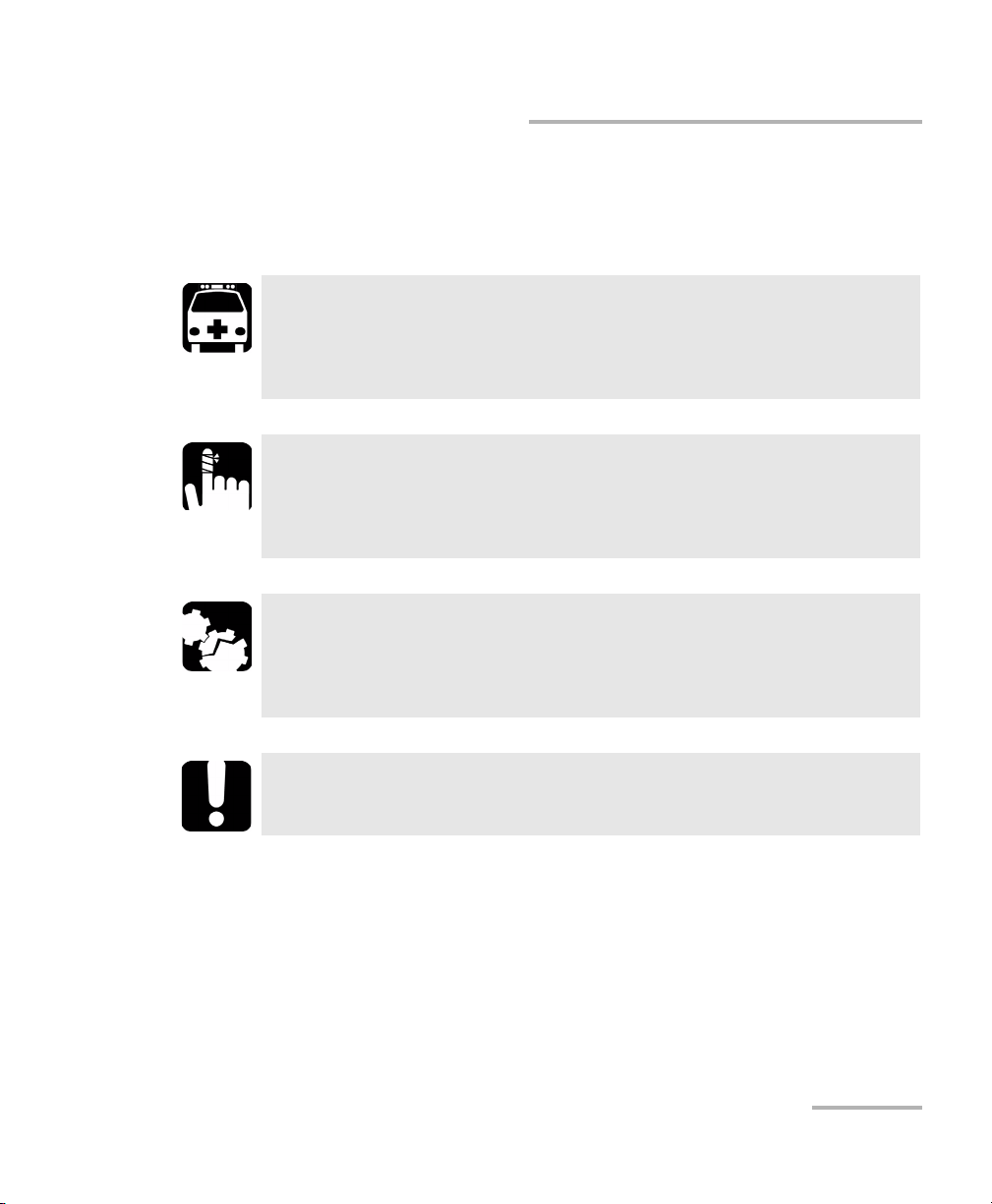
Before using the product described in this manual, you should understand
the following conventions:
WARNING
Indicates a potentially hazardous situation which, if not avoided,
could result in death or serious injury. Do not proceed unless you
understand and meet the required conditions.
CAUTION
Indicates a potentially hazardous situation which, if not avoided,
may result in minor or moderate injury. Do not proceed unless you
understand and meet the required conditions.
CAUTION
Indicates a potentially hazardous situation which, if not avoided,
may result in component damage. Do not proceed unless you
understand and meet the required conditions.
IMPORTANT
Refers to information about this product you should not overlook.
SONET/SDH Application 5
Page 20

Page 21
2 Safety Information
Laser Safety Warnings
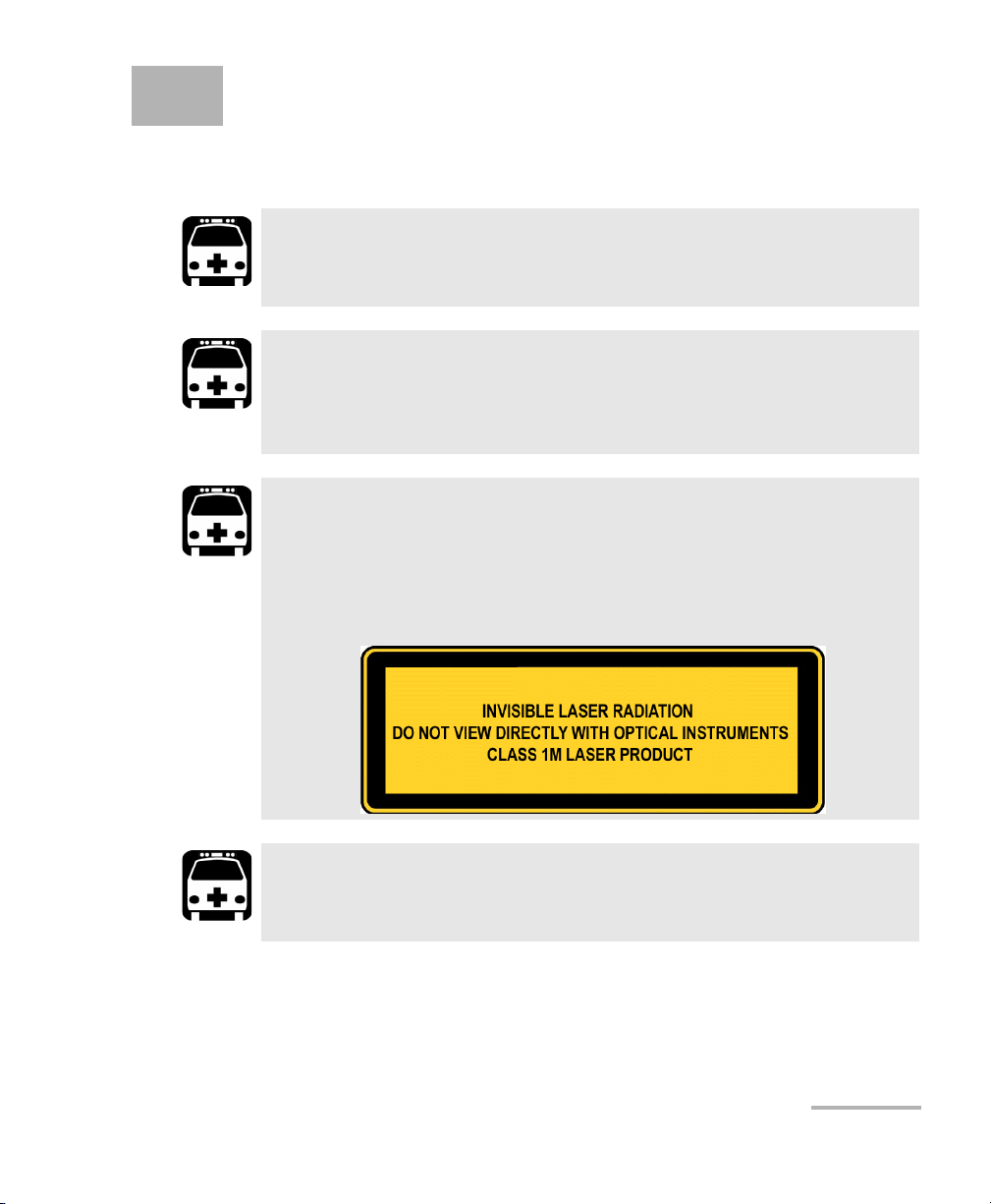
WARNING
When the LASER LED is on or flashing, the IQS-8100 Series is
transmitting an optical signal.
WARNING
Do not install or terminate fibres while a laser source is active.
Never look directly into a live fibre, and ensure that your eyes are
protected at all times.
WARNING
This product may employ a Class 1M SFP or XFP. Check pluggable
transceiver label for laser classification. Applies to IQS-8115,
IQS-8120, IQS-8120NG, IQS-8120NGE, IQS-8130, IQS-8130NG, and
IQS-8130NGE modules only.
WARNING
Use of optical instruments with this product will increase eye
hazard.
SONET/SDH Application 7
Page 22

Safety Information
Installation Instruction Warnings
Installation Instruction Warnings
This unit is designed for indoor use only.
For IQS-8105/15/20/30: Except for the Dual Bantam connector and
the RJ-48C port, all telecom (electrical) interfaces are SELV (Safety
Extra Low Voltage) circuitry intended for intra-building use only.
To reduce the risk of fire, use only No. 26 AWG or larger
telecommunication line cord.
For IQS-8140: The AUX (BNC) interface employs SELV (Safety Extra
Low Voltage) circuitry intended for intra-building use only.
No user serviceable parts are contained inside. Contact the
manufacturer regarding service of this equipment.
CAUTION
CAUTION
CAUTION
CAUTION
Keep all ventilation openings clear and unobstructed.
IMPORTANT
All wiring and installation must be in accordance with local building
and electrical codes acceptable to the authorities in the countries
where the equipment is installed and used.
8 IQS-8100 Series Transport Blazer
Page 23

Safety Information
Installation Instruction Warnings
CAUTION
Electrostatic Discharge (ESD) Sensitive Equipment:
Plug-in modules can be damaged by static electrical discharge. To
minimize the risk of damage, dissipate static electricity by touching
a grounded unpainted metal object
³ before removing, inserting, or handling the module.
³ before connecting or disconnecting cables to/from the module.
³ before inserting or removing SFP/XFPs to/from the module.
SONET/SDH Application 9
Page 24

Page 25

3 Getting Started
If the IQS-8100 Series Transport Blazer has been purchased at the same
time as the IQS-600, the IQS-8100 Series module is pre-installed with the
appropriate IQS Manager software version.
IQS Manager Installation
The IQS Manager is the baseline software and thus needs to be installed on
the IQS-600 before using the IQS-8100 Series module.
Note: Refer to the IQS-600 platform user guide for more information on IQS
Manager installation procedure.
Inserting and Removing Test Modules
CAUTION
Never insert or remove a module while the controller unit and its
expansion units are turned on. This will result in immediate and
irreparable damage to both the module and unit.
Note: Refer to the IQS-600 platform user guide for more information on how to
insert a module into the IQS-600 or to remove a module from the IQS-600.
For IQS-8140, use respectively the retaining screw number 2, 3, or 4 (from
bottom to top) depending if the module is inserted in slots 0 to 5, 1 to 6, or 2
to 7.
Turning the Unit On
Turn on the IQS-600. Refer to the IQS-600 platform user guide for more
information.
SONET/SDH Application 11
Page 26

Page 27
4 Physical Interfaces and LEDs
This section describes the connectors (ports) and LEDs available on each
module.
Modules
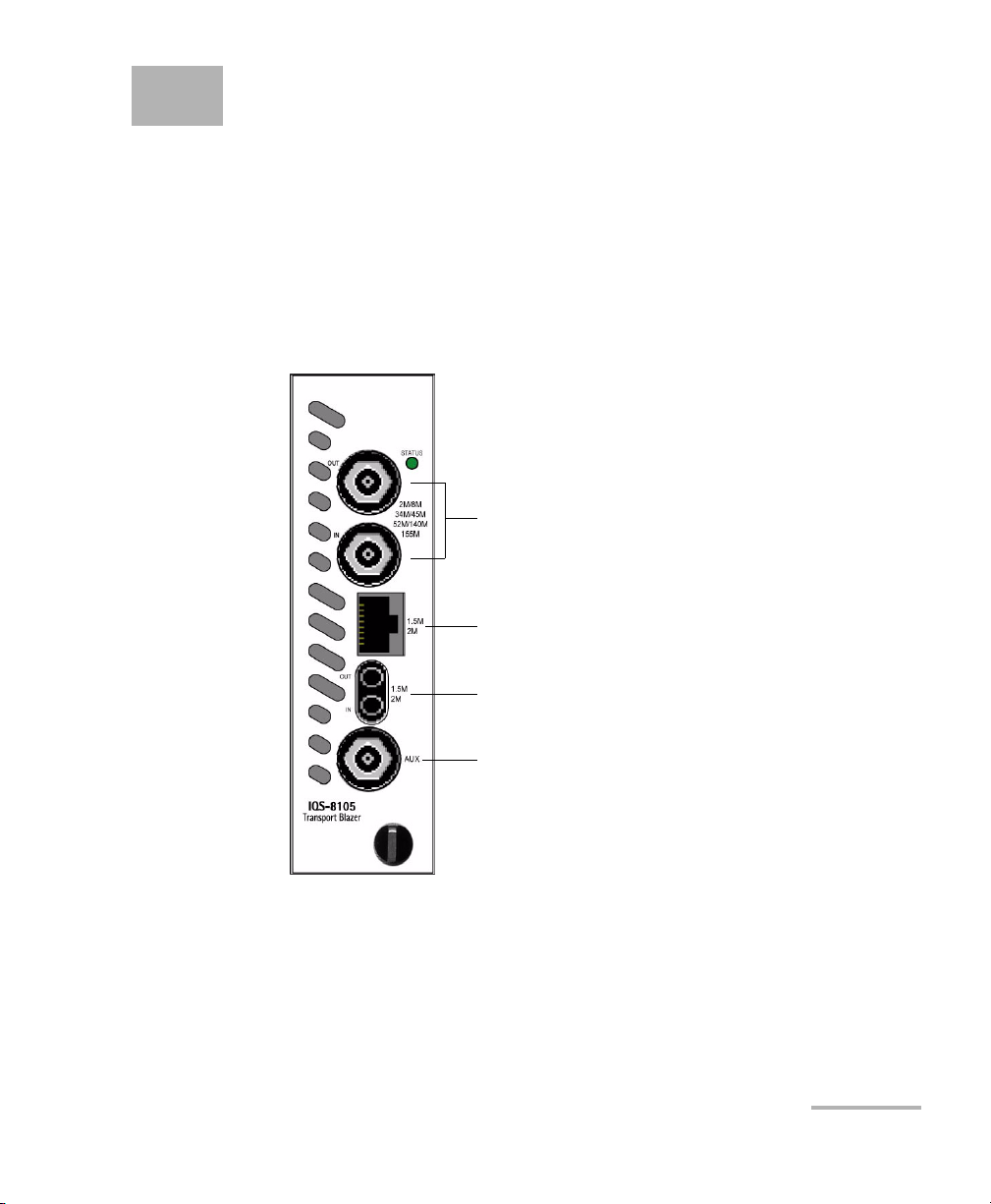
IQS-8105 Module
SONET/SDH analyzer up to 155 Mbps.
E1/2M, E2/8M, E3/34M, DS3/45M,
STS-1e/STM-0e, E4/140M,
STS-3e/STM-1e
DS1/1.5M, E1/2M (RJ-48C port)
DS1/1.5M, E1/2M (Bantam
AUX DS1/E1/2MHz IN/OUT (Clock Sync.) or
second port for DS1/DS3 dual RX
SONET/SDH Application 13
Page 28
Physical Interfaces and LEDs
Modules
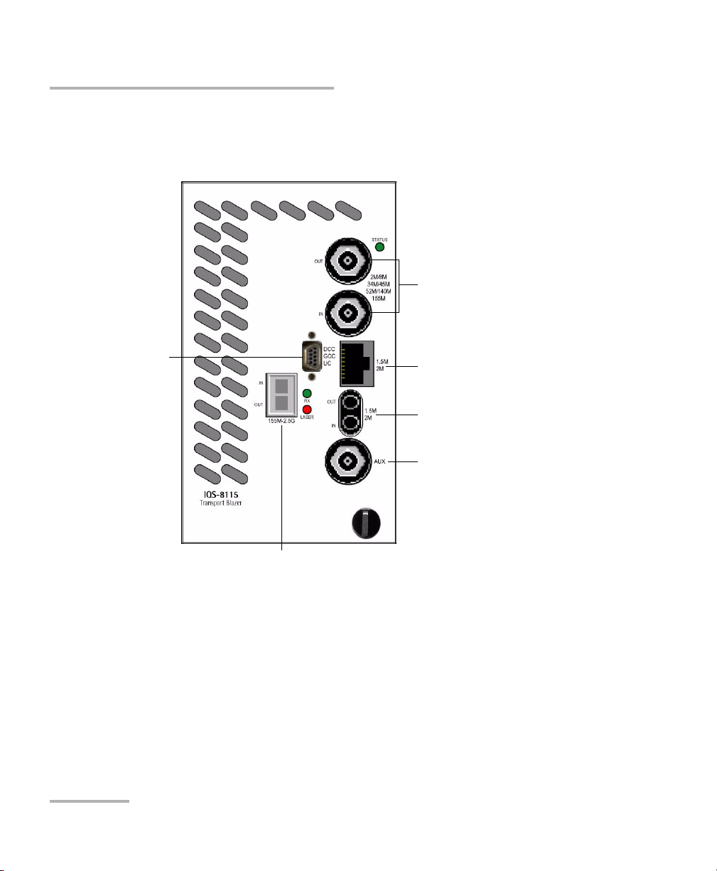
IQS-8115 Module
SONET/SDH analyzer up to 2.5 Gbps.
DCC/GCC/UC
(future use)
E1/2M, E2/8M, E3/34M,
DS3/45M, STS-1e/STM-0e,
E4/140M, STS-3e/STM-1e
DS1/1.5M, E1/2M (RJ-48C port)
DS1/1.5M, E1/2M (Bantam port)
AUX DS1/E1/2MHz IN/OUT (Clock
Sync.) or second port for DS1/DS3
dual RX
OC-3/STM-1, OC-12/STM-4, OC-48/STM-16
14 IQS-8100 Series Transport Blazer
Page 29
Physical Interfaces and LEDs
Modules
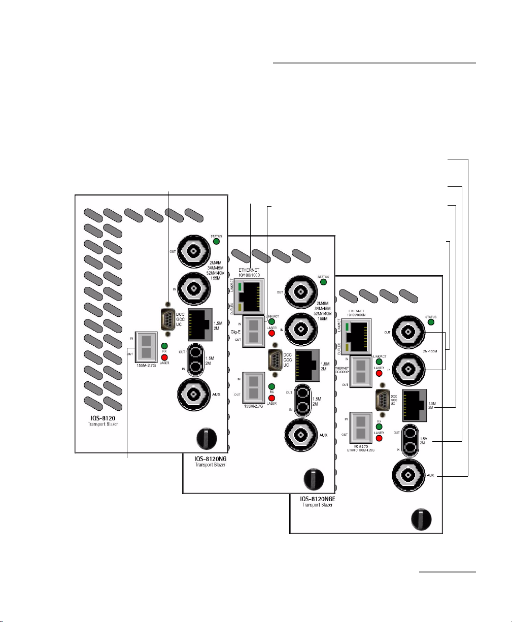
IQS-8120/IQS-8120NG/IQS-8120NGE Module
SONET/SDH/OTN analyzer up to 2.7 Gbps. The IQS-8120NGE also offers
1 Gbps Ethernet and up to 4x Fibre Channel testing; refer to the “Ethernet
and Fibre Channel Application” user guide for more information.
AUX DS1/E1/2MHz IN/OUT (Clock Sync.)
DCC/GCC/UC
(future use)
Ethernet ADD/DROP
10/100/1000M
electrical
Ethernet
ADD/DROP
Gig-E optical
or second port for DS1/DS3 dual RX
DS1/1.5M, E1/2M (Bantam port)
DS1/1.5M, E1/2M (RJ-48C port)
E1/2M, E2/8M, E3/34M,
DS3/45M, STS-1e/STM-0e,
E4/140M, STS-3e/STM-1e
OC-3/STM-1,
OC-12/STM-4,
OC-48/STM-16/OTU1
SONET/SDH Application 15
Page 30
Physical Interfaces and LEDs
Modules
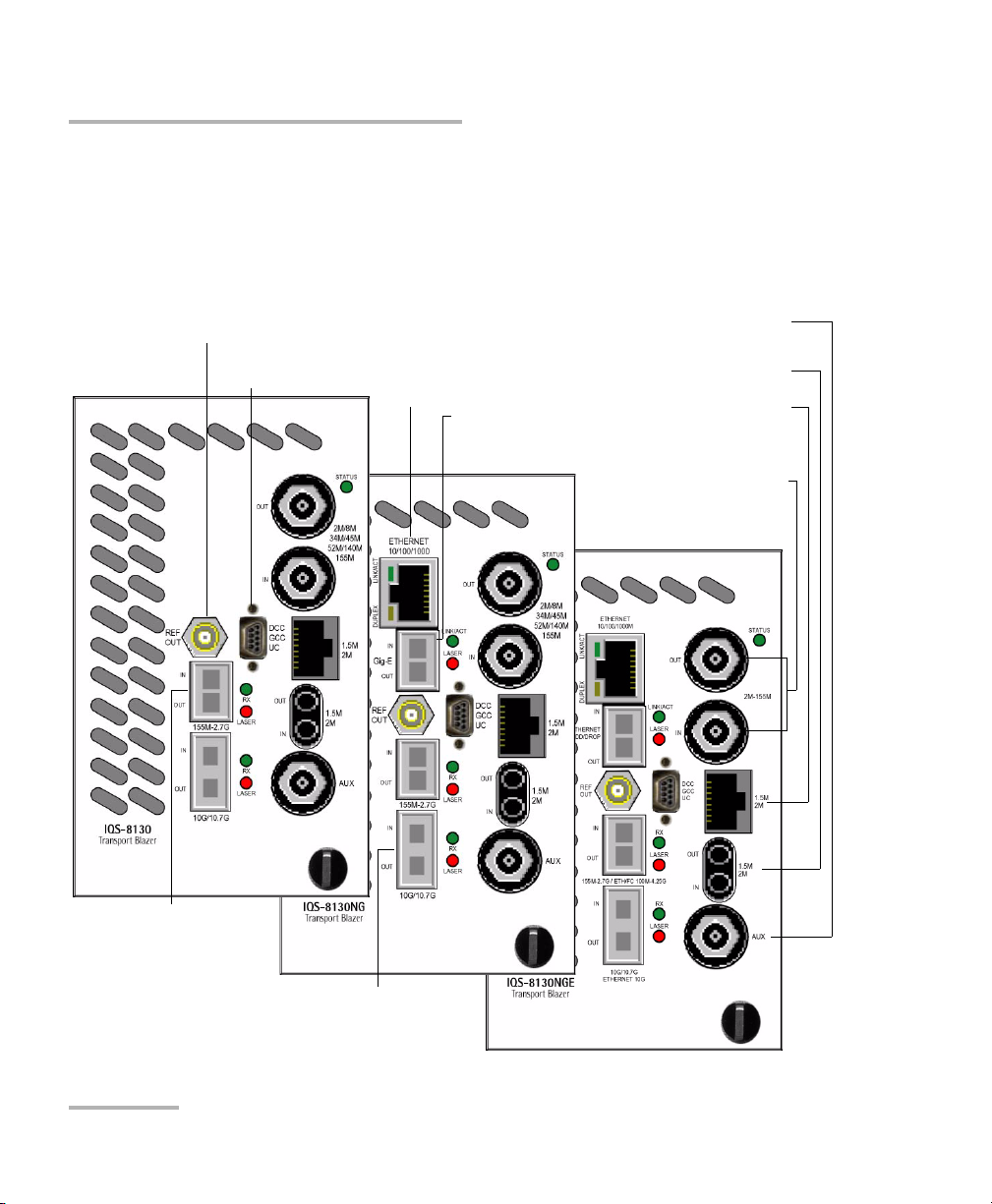
IQS-8130/IQS-8130NG/IQS-8130NGE Module
SONET/SDH/OTN analyzer up to 11.1 Gbps. The IQS-8130NGE also offers
10 Gbps Ethernet and up to 10x Fibre Channel; refer to the “Ethernet and
Fibre Channel Application” user guide for more information.
REF OUT (Clock reference for eye diagram) available with
OC-192/STM-64/OTU2/OTU1e/OTU2e/OTU1f/OTU2f
configuration
DCC/GCC/UC
(future use)
Ethernet ADD/DROP
10/100/1000M
electrical
Ethernet
ADD/DROP
Gig-E optical
AUX DS1/E1/2MHz IN/OUT (Clock Sync.)
or second port for DS1/DS3 dual RX
DS1/1.5M, E1/2M (Bantam port)
DS1/1.5M, E1/2M (RJ-48C port)
E1/2M, E2/8M, E3/34M,
DS3/45M, STS-1e/STM-0e,
E4/140M, STS-3e/STM-1e
OC-3/STM-1,
OC-12/STM-4,
OC-48/STM-16/OTU1
OC-192/STM-64/OTU2/
OTU1e/OTU2e/OTU1f/OTU2f
16 IQS-8100 Series Transport Blazer
Page 31
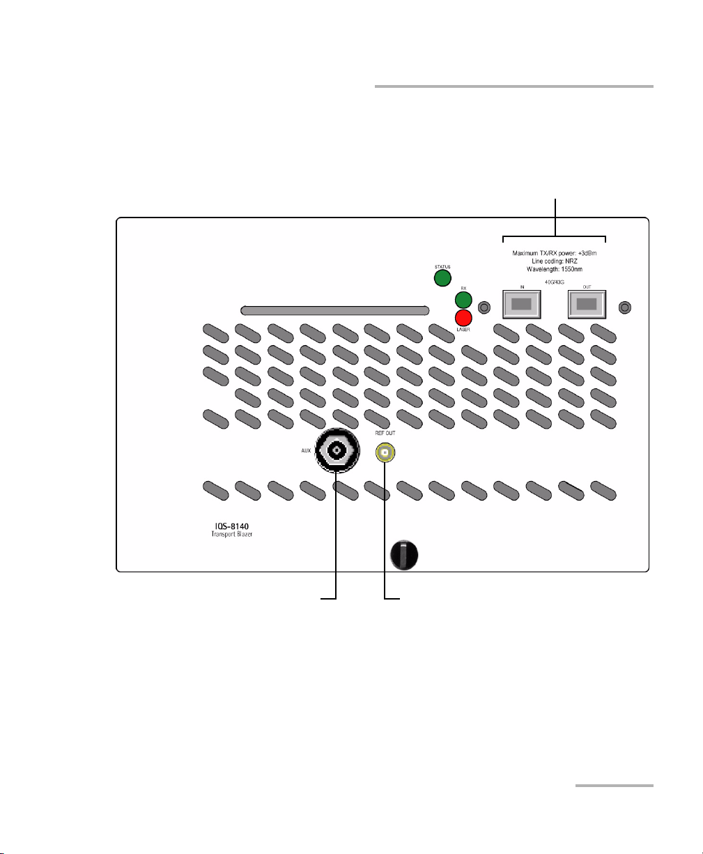
IQS-8140
SONET/SDH/OTN 40/43 Gbps analyzer.
Physical Interfaces and LEDs
Modules
OC-768/STM-256/OTU3 optical ports
Clock (AUX)
Clock (REF OUT)
Two models are available:
³ IQS-8140-NRZ: SONET/SDH/OTN test module with 40/43 Gbit/s,
1550 nm, NRZ 2 km transponder.
³ IQS-8140-DPSK: SONET/SDH/OTN test module with 40/43 Gbit/s,
tunable DPSK transponder.
SONET/SDH Application 17
Page 32

Physical Interfaces and LEDs
Port Availability on IQS-8100 Series Module
Port Availability on IQS-8100 Series Module
The following table shows the list of available ports as well as a description
and signals supported for each module. For Ethernet and Fibre Channel
ports, refer to the “Ethernet and Fibre Channel Application” user guide.
Port labelled Description Supported signal(s) Module
155M-2.5G Optical IN/OUT port
small form factor
pluggable (SFP)
155M-2.7G Optical IN/OUT port
small form factor
pluggable (SFP)
100M-4.25G Optical IN/OUT port
small form factor
pluggable (SFP)
10G/10.7G Optical IN/OUT port
10G small form factor
pluggable (XFP)
40G/43G Optical IN/OUT OC-768/STM-256, OTU3 IQS-8140
2M/8M/34M/
45M/52M/
140M/155M, or
2M-155M
1.5M/2M Electrical IN/OUT port
1.5M/2M Electrical port RJ-48C DS1/1.5M, E1/2M IQS-8100
AUX Electrical port BNC DS1/1.5M/E1/2M/2 MHz signal for
Electrical IN/OUT port
BNC
Bantam
OC-3/STM-1, OC-12/STM-4,
OC-48/STM-16
OC-3/STM-1, OC-12/STM-4,
OC-48/STM-16, OTU1
OC-3/STM-1, OC-12/STM-4,
OC-48/STM-16, OTU1, Ethernet
100Mbps, Ethernet 1000Mbps, FC
1x, FC 2x, FC 4x
OC-192/STM-64, OTU2, OTU2e,
OTU1e, OTU1f, OTU2f,
Ethernet 10Gig (IQS-8130NGE), FC
10x (IQS-8130NGE)
E1/2M, E2/8M, E3/34M, DS3/45M,
STS-1e/STM-0e/52M, E4/140M,
STS-3e/STM-1e/155M
DS1/1.5M, E1/2M IQS-8100
external clock synchronization, or
DS1/DS3 signal for Dual RX test.
IQS-8115
IQS-8120
IQS-8120NG
IQS-8130
IQS-8130NG
IQS-8120NGE
IQS-8130NGE
IQS-8130
IQS-8130NG
IQS-8130NGE
IQS-8105/15/2
0/30
Series
Series
IQS-8100
Series
18 IQS-8100 Series Transport Blazer
Page 33

Physical Interfaces and LEDs
Port Availability on IQS-8100 Series Module
Port labelled Description Supported signal(s) Module
REF OUT Reference output port
SMA
See Clock Interface Connections
on page 23 for more information.
IQS-8130
IQS-8130NG
IQS-8130NGE
Ethernet
10/100/1000M
Gig-E /
ETHERNET
ADD/DROP
Electrical Ethernet
port RJ-45
Optical IN/OUT
Ethernet port small
form pluggable (SFP)
DCC GCC UC Electrical IN/OUT
micro DB-9 female
DCE for DCC, GCC
and UC signals.
10/100/1000 Mbps (electrical) IQS-8120NG
IQS-8130NG
IQS-8120NGE
IQS-8130NGE
1000 Mbps (optical) IQS-8120NG
IQS-8130NG
IQS-8120NGE
IQS-8130NGE
Future use IQS-8115
IQS-8120
IQS-8120NG
IQS-8130
IQS-8130NG
IQS-8120NGE
IQS-8130NGE
SONET/SDH Application 19
Page 34
Physical Interfaces and LEDs
OTN/OC-N/STM-N Interface Connections
OTN/OC-N/STM-N Interface Connections
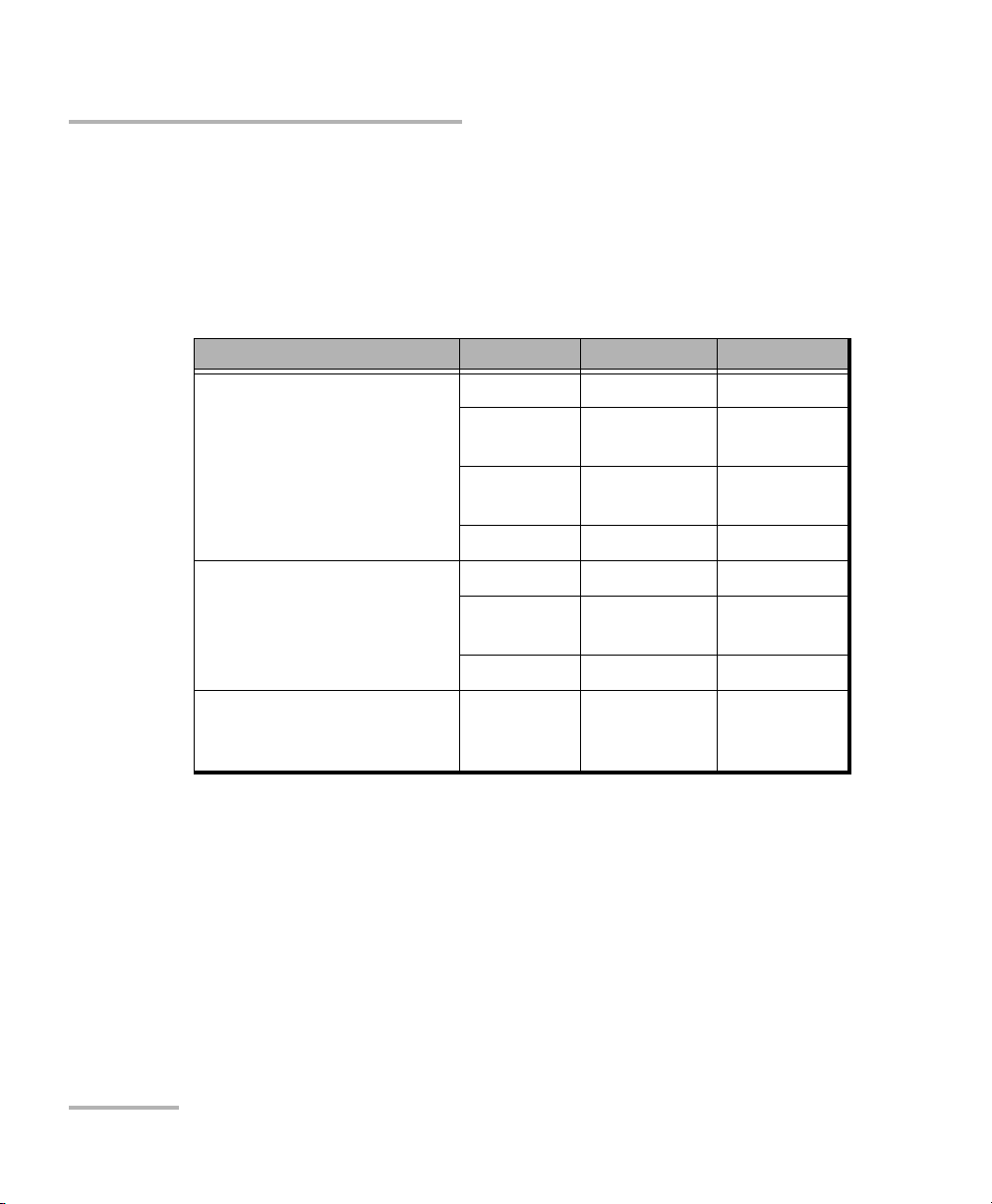
For IQS-8115/IQS-8120/IQS-8120NG/IQS-8120NGE/IQS-8130/IQS-8130NG/
IQS-8130NGE, plug the supplied SFP/XFP module into the respective slot
on the module. Only use EXFO qualified SFP/XFPs. Using non-qualified
SFP/XFPs can affect the Performance and accuracy of the optical port.
Description Wavelength Reach Part Number
Multirate (155/622 Mbps,
2.5/2.7 Gbps/FC 1x/2x)
optical SFP transceiver
module with LC connector
Multirate (10/10.7 Gbps)
optical XFP transceiver
module with LC connector
Multirate (10/11.3 Gbps)
optical XFP transceiver
module with LC connector
Note: Do not replace a SFP/XFP while the test is running to avoid distorting
statistics. First stop the test case, replace the SFP/XFP and then restart the
test.
1310 nm short (15 Km) FTB-8190
1310 nm intermediate
(40 Km)
1550 nm intermediate
(40 Km)
1550 nm long (80 Km) FTB-8192
1310 nm Short (10 Km) FTB-81900
1550 nm Intermediate
(40 Km)
1550 nm Long (80 Km) FTB-81902
1310 nm Short (10 Km) FTB-81903
FTB-8191
FTB-8193
FTB-81901
20 IQS-8100 Series Transport Blazer
Page 35

Physical Interfaces and LEDs
OTN/OC-N/STM-N Interface Connections
Carefully connect optical fibre cables to the SFP/XFP’s (IQS-8115, IQS-8120,
IQS-8120NG, IQS-8120NGE, IQS-8130, IQS-8130NG, and IQS-8130NGE) or
transponder (IQS-8140) IN and OUT ports. To ensure good signal quality,
make sure that the optical fibre connector is fully inserted into the optical
connector port.
CAUTION
To prevent exceeding the maximum input power level please use an
attenuator when a loopback configuration is used.
³ LASER red LED: The LASER LED is on when the IQS-8100 Series is
emitting an optical laser signal.
³ RX green LED: The RX LED is on when the IQS-8100 Series is receiving
an optical laser signal.
SONET/SDH Application 21
Page 36

Physical Interfaces and LEDs
Electrical SONET/DSn/SDH/PDH Interface Connection
Electrical SONET/DSn/SDH/PDH Interface
Connection
³ 2M/8M/34M/45M/52M/140M/155M port: The IQS-8105/15/20/30
provides two BNC connectors, labeled 2M-155M or
2M/8M/34M/45M/52M/140M/155M IN and OUT, for E1/2M, E2/8M,
E3/34M, DS3/45M, STS-1e/STM-0e/52M, E4/140M, STS-3e/STM-1e/155M
testing capability. Connector type is BNC for coaxial 75-ohm cable
connection.
³ 1.5M/2M Bantam port: The IQS-8105/15/20/30 provides an IN/OUT
Bantam connectors for DS1/1.5M and E1/2M testing capability.
³ 1.5M/2M RJ-48C port: The IQS-8105/15/20/30 provides an IN/OUT
RJ-48C connectors for DS1/1.5M and E1/2M testing capability.
Note: Dual RX test case uses the BNC labelled AUX as the second RX port.
Connect the signal to be tested to the corresponding port.
22 IQS-8100 Series Transport Blazer
Page 37
Physical Interfaces and LEDs
Clock Interface Connections
Clock Interface Connections
³ AUX port: The IQS-8100 Series provides one connector, labeled AUX,
that can be used either for DS1 (1.5M)/E1 (2M)/2 MHz external clock
synchronization signal or as the second RX port for Dual RX (DS1 or
DS3) testing (IQS-8105/15/20/30). This port is unidirectional and can be
used either for input or output. Connector type is BNC for coaxial
75-ohm cable connection. An adapter cable (BNC to Bantam) is
required for Bantam connection (not supplied).
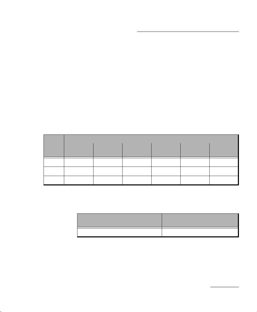
³ REF OUT port: The IQS-8130/IQS-8130NG/IQS-8130NGE/IQS-8140
provides one connector, labeled REF OUT, that can be used for the
following clock signals. Connector type is SMA.
For OC-192/STM-64/OTU2/OTU1e/OTU2e/OTU1f/OTU2f
Clock
divider
OC-192/
STM-64
OTU2 OTU1e OTU2e OTU1f OTU2f
Output frequency for
16 622.08 MHz 669.33 MHz 690.57 MHz 693.48 MHz 704.38 MHz 707.35 MHz
32 311.04 MHz 334.66 MHz 345.29 MHz 346.74 MHz 352.19 MHz 353.68 MHz
64 155.52 MHz 167.33 MHz 172.64 MHz 173.37 MHz 176.10 MHz 176.84 MHz
For OC-768/STM-256/OTU3
Output frequency for
OC-768/STM-256
Output frequency for OTU3
2488.3 MHz 2688.7 MHz
SONET/SDH Application 23
Page 38
Physical Interfaces and LEDs
Ethernet 10/100/1000Base-T Interface Connection
Ethernet 10/100/1000Base-T Interface
Connection
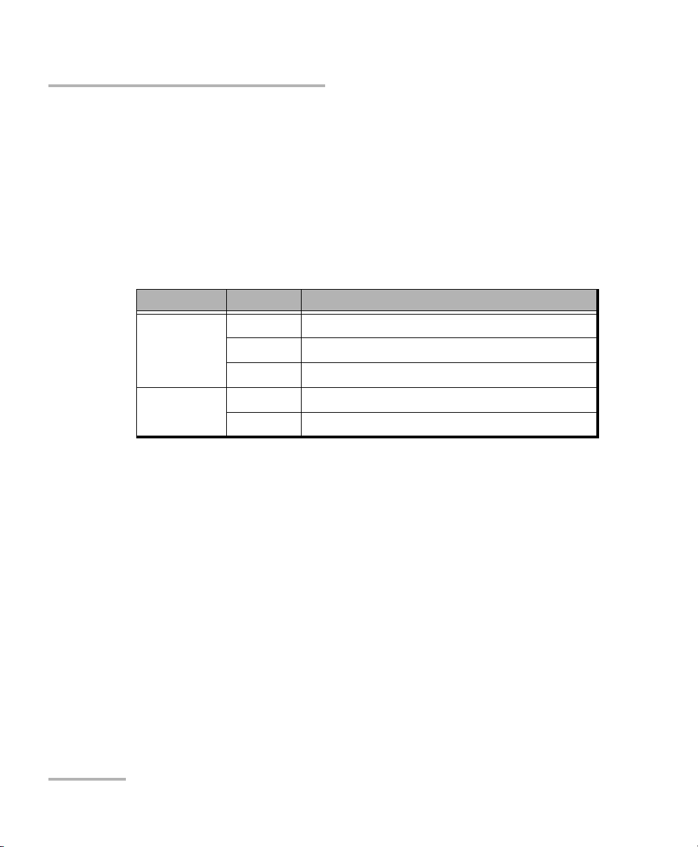
ETHERNET 10/100/1000M port: The IQS-8120NG/IQS-8130NG/
IQS-8120NGE/IQS-8130NGE provides an Ethernet port for electrical
10/100/1000 Mbps Ethernet connection allowing Ethernet testing through
GFP.
Connect the signal to be tested to the ETHERNET 10/100/1000M RJ-45 port.
LED Status Description
LINK/ACT On Ethernet link up.
Off Ethernet link down.
Flash TX/RX activity.
DUPLEX On Full Duplex mode.
Flash Collisions are detected.
24 IQS-8100 Series Transport Blazer
Page 39
Physical Interfaces and LEDs
Ethernet ADD/DROP Gig-E Interface Connection
Ethernet ADD/DROP Gig-E Interface
Connection
ETHERNET ADD/DROP or Gig-E port: The IQS-8120NG/IQS-8130NG/
IQS-8120NGE/IQS-8130NGE provides a 1Gig-E port for optical 1000Base-X
Ethernet connection allowing GFP and Ethernet testing.
Plug the supplied SFP modules into the ETHERNET ADD/DROP or Gig-E
slot.
Only use EXFO qualified SFPs. Using non-qualified SFPs can affect the
Performance and accuracy of the optical port.
Supported SFPs
Description Wavelength Reach Part Number
GigE/FC/2FC optical SFP
transceiver module with LC
connector
Multirate (155/622 Mbps,
2.5/2.7 Gbps/FC 1x/2x)
optical SFP transceiver
module with LC connector
³ The LASER LED lights up indicating that the Gig-E port is emitting an
optical signal.
³ The RX LED lights up indicating that the Gig-E port is receiving data.
SONET/SDH Application 25
850 nm MMF < 500 m FTB-8590
1310 nm 10 Km FTB-8591
1550 nm 90 Km FTB-8592
1310 nm short (15 Km) FTB-8190
1310 nm intermediate
(40 Km)
1550 nm intermediate
(40 Km)
1550 nm long (80 Km) FTB-8192
FTB-8191
FTB-8193
Page 40

Physical Interfaces and LEDs
DCC/GCC/UC Interface Connection
DCC/GCC/UC Interface Connection
These interfaces are not currently supported.
Status LED
Indicates the status of the IQS-8100 Series module. The STATUS LED is
green when the module is active and operates normally. The STATUS LED
is yellow when the module is in the booting process. The STATUS LED is
red to indicate a failure of the module.
26 IQS-8100 Series Transport Blazer
Page 41

5 Introducing and Using the
Graphical User Interface
Starting the IQS-8100 Series Transport Blazer Application
To Start the IQS-8100 Series Application:
1. Once your IQS-8100 Series module is installed, turn on the IQS-600.
2. In the IQS Manager main window, under Modules, press IQS-8105,
IQS-8115, IQS-8120, IQS-8120NG, IQS-8130, IQS-8130NG, IQS-8120NGE,
IQS-8130NGE, or IQS-8140 once to select the module.
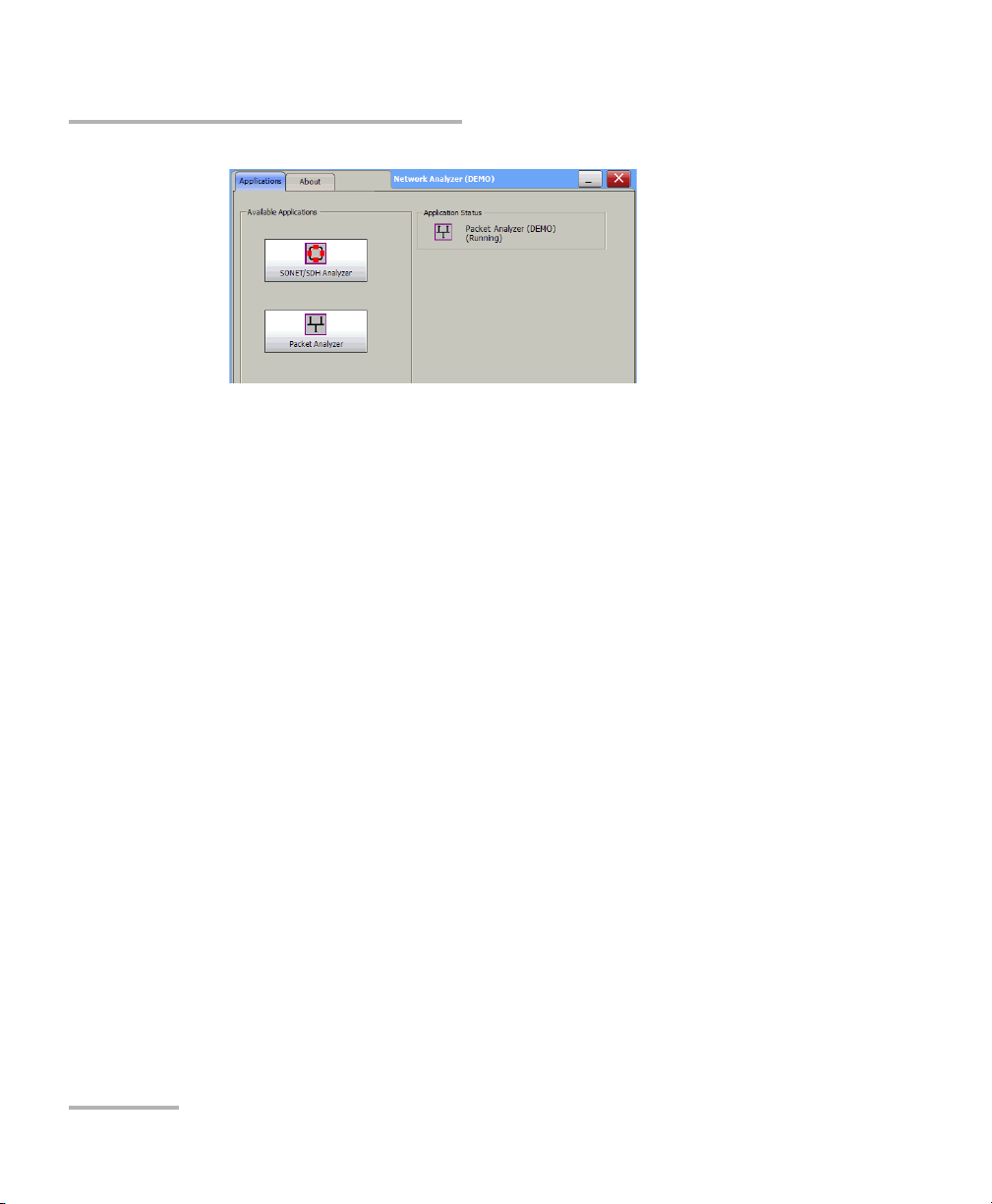
3. Press Start Application to start the module application or the Network
Analyzer.
4. This step applies to the IQS-8120NGE/IQS-8130NGE module only. The
Network Analyzer allows to either run the SONET/SDH or the Packet
Analyzer. Both analyzers cannot run simultaneously. Press
SONET/SDH Analyzer to start the module for SONET/SDH/OTN test.
SONET/SDH Application 27
Page 42
Introducing and Using the Graphical User Interface
Starting the IQS-8100 Series Transport Blazer Application
Note: Refer to the Ethernet and Fibre Channel Application user guide for more
information on Packet Analyzer.
The exit button ( X ) closes the Network Analyzer, SONET/SDH
Analyzer, and/or Packet Analyzer applications. If a test is created, one
of the following confirmation messages is displayed, based on the
standalone feature status (enabled or not). Refer to the IQS-600 user
guide for more information on the standalone feature.
³ The following message is displayed when exiting the GUI while a
test is created and standalone is disabled.
Are you sure you want to exit the Network Anlyzer, SONET/SDH
Analyzer, and Packet Analyzer? Any unsaved information will be
lost.
³ The following message is displayed when exiting the GUI while a
test is created and standalone is enabled.
Exiting the application will maintain the module alive as the
Standalone mode is enabled. Are you sure you want to exit?
28 IQS-8100 Series Transport Blazer
Page 43
Introducing and Using the Graphical User Interface
/
Main Window
Main Window
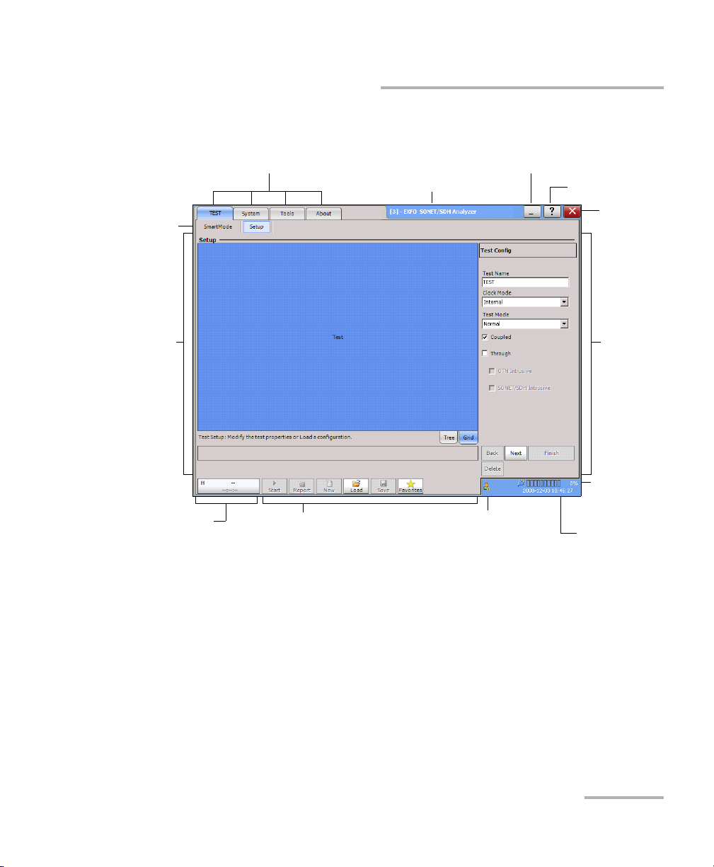
Ta bs
Content of
tab
Global test status
Ta bs
Test controls
Application title
Remote status
Minimize (remote control)
Help
Exit
Content of
tab
Battery level
AC power
Date and time
SONET/SDH Application 29
Page 44

Introducing and Using the Graphical User Interface
Main Window
Tabs
The GUI application contains the following four main application tabs that
contain other tabs.
³ TEST Tab
The TEST tab gives access to the test creation, configuration, and
results.
SmartMode is part of the TEST tab and allows to automatically identify
the structure of the selected SONET/SDH signal rate that is connected
to the Transport Blazer module. Refer to Smart Mode on page 111 for
more information. Not available on the IQS-8140.
Setup is part of the TEST tab and allows setting up the test. Refer to
page 62 for more information.
Once the test is created, other tabs are enabled allowing configuration
of test parameters and viewing of the test status and results.
30 IQS-8100 Series Transport Blazer
Page 45

Introducing and Using the Graphical User Interface
In this user guide, the tabs are grouped as shown below:
³ Summary Tabs on page 125
³ Por t Tabs on page 137
³ OTN Tabs on page 153
³ SONET Tabs on page 211
³ DSn Tabs on page 269
³ SDH Tabs on page 303
³ PDH Tabs on page 369
³ Ethernet Tabs on page 393
³ BERT Tabs on page 405
³ Advanced Tabs on page 411
³ Next-Generation Tabs on page 429
³ Common Tabs on page 491
Main Window
³ System tab; refer to page 519 for more information.
³ Tool s tab; refer to page 551 for more information.
³ About tab; gives information on EXFO company, contact, and product
software release version.
SONET/SDH Application 31
Page 46

Introducing and Using the Graphical User Interface
Main Window
Application Title
Displays the software application title which is
[x] - EXFO SONET/SDH Analyzer. Where x is the slot ID in which the
module is inserted.
A module description appears in front of the [x] slot ID when defined in
IQS Manager. Refer to Tool s, Remote Control Configuration, and Module
Description field from the IQS-600 user guide for more information.
For Visual Guardian Lite, the IP address of the IQS-600 is inserted after the
[x] slot ID.
For example: Module #1 - [2] - 10.1.200.25 - EXFO SONET/SDH Analyzer
Minimize
The minimize button ( _ ) allows minimization of a remote GUI application
(Visual Guardian Lite).
32 IQS-8100 Series Transport Blazer
Page 47

Introducing and Using the Graphical User Interface
Main Window
Help
The help button ( ? ) displays the help information on the current window.
A window pops up to select the area of the application where help is
required. Press OK and the help information is immediately displayed.
It is also possible to navigate through the help information once the help
window is open.
SONET/SDH Application 33
Page 48

Introducing and Using the Graphical User Interface
Main Window
Exit
For IQS-8105, IQS-8115, IQS-8120, IQS-8120NG, IQS-8130, IQS-8130NG, and
IQS-8140: The exit button ( X ) closes the current application. If a test is
created, one of the following confirmation messages is displayed, based
on the standalone feature status (enabled or not). Refer to the IQS-600 user
guide for more information on the standalone feature.
³ The following message is displayed when exiting the GUI while a test is
created and standalone is disabled.
Are you sure you want to exit the IQS-8100 Series Transport Blazer?
Any unsaved information will be lost.
³ The following message is displayed when exiting the GUI while a test is
created and standalone is enabled.
Exiting the application will maintain the module alive as the
Standalone mode is enabled. Are you sure you want to exit?
For IQS-8120NGE, and IQS-8130NGE: The exit button ( X ) switches from
the current application to the Network Analyzer application. If the test is
running, a user confirmation is required to stop the test before switching
the application. The swiching puts the application in idle mode meaning
that the test case configuration is kept and will be recovered when
returning to that application.
34 IQS-8100 Series Transport Blazer
Page 49
Introducing and Using the Graphical User Interface
Global Test Status and Controls
Global Test Status and Controls
Global Test Status
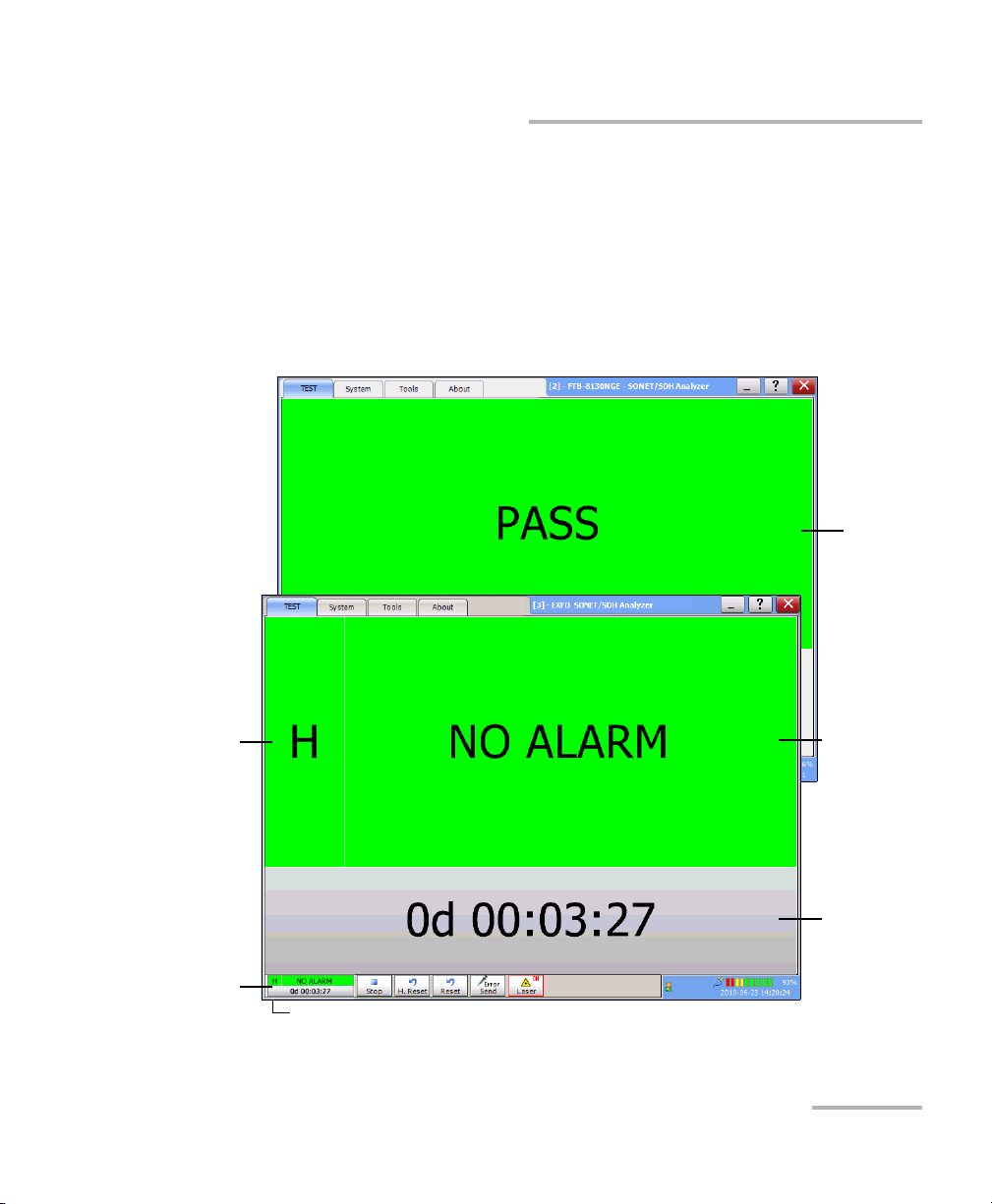
The global test status button displays the alarm, pass/fail verdict, and test
timer. Clicking on this button maximizes the view of these status. The
maximized view is useful to facilitate distant viewing of these status.
Verdict
Alarm/Error
History
Global Test
Status
Button
Tes t T i mer I c o n
SONET/SDH Application 35
Current
Status
Te s t Tim e r
Page 50

Introducing and Using the Graphical User Interface
Global Test Status and Controls
To minimize the view, either click on the global test status button or click
anywhere on the maximized status area.
History and current status are reported for all tests at the exception of
Multi-Channel SDT test mode which reports the pass/fail verdict when
enabled.
³ H (History): Indicates if alarms/errors occurred in the past. A grey
background indicates that the test did not run yet, a green background
indicates that no alarm/error has occurred, while a red background
indicates that at least one alarm/error has occurred.
³ Current status: Indicates the current alarm/error status of the test.
A grey background indicates that the test is not running (--), a green
background indicates that there is no alarm/error active (NO ALARM),
while a red background indicates that at least one alarm/error
condition is active (ALARM).
Note: The history and current alarm/error status are monitored once the test is
started.
³ Verdict: Reports the SDT test verdict status when enabled. Only
available with Multi-Channel SDT test mode.
³ PASS is displayed with a green background when all SDT result
values are smaller or equal to the configured SDT threshold.
³ FAIL is displayed with a red background when any SDT result value
is bigger than the configured SDT threshold.
³ “--” is displayed with a gray background when either the SDT
threshold is not enabled or the test has not run yet.
³ The test timer indicates the time elapsed since the beginning of the
test. The test timer format is “day hour:minute:second”.
³ The test timer icon indicates that the timer configuration is enabled.
Refer to Timer Configuration on page 130 for more information.
36 IQS-8100 Series Transport Blazer
Page 51
Introducing and Using the Graphical User Interface
Test Controls
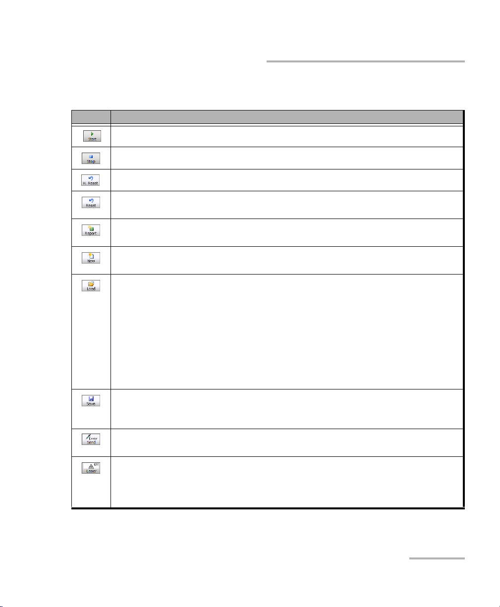
Button Description
Starts the test. Start is available when the test is created and not running.
Global Test Status and Controls
Stops the test.
Resets the history (H) alarm and error LEDs.
a
a
Resets counters (seconds, count, and rate), test timer and both history (H) and
current (C) LEDs for the entire test case. Also resets the logger.
Generates a report of the current test. See Test Report Generation on page 42
for more information.
Clears the current test. A user’s confirmation is required before clearing the
b
test.
b
a
Loads a previously saved configuration. Select an existing file and press Open
to confirm. The default directory is
d:\IQSManager\User Files\SonetSdhAnalyzerG2\Configuration. The
configuration file extension is cfg.
b
An error message is displayed and the configuration is not loaded when the file
is corrupted, the module is not properly installed, the hardware or software
options are not compatible, invalid configuration (IQS-8105/15/20/30), or when
the resources or power are not sufficient. Refer to Solving Common Problems
on page 561 for more information.
Saves the current test configuration. Select an existing file, or type a new name
in the File name field, and press Save. The default directory is
d:\IQSManager\User Files\SonetSdhAnalyzerG2\Configuration.
b
Generates pattern bit error according to the amount selected on the Pattern
TX tab. Refer to Pattern Error Injection on page 408.
a
Indicates that the laser control is off. Pressing this button will activate the laser
immediately by emitting an optical laser signal. This button is only available for
optical interfaces. The laser is On by default when the test is created unless
otherwise set from the Default Test Preferences on page 530.
SONET/SDH Application 37
Page 52

Introducing and Using the Graphical User Interface
Global Test Status and Controls
Button Description
Indicates that the laser control is on. Pressing this button will turn off the laser.
This button is only available for optical interfaces. The laser is On by default
when the test is created unless otherwise set from the Default Test Preferences
on page 530. The laser control button is not affected when turning off the laser
by generating a LOS for example.
Provides access to 10 default or customer defined test case configurations. See
Favorites on page 40 for more information.
b
Allows the detection of the Line Coding, Framing, and Test Pattern of the
selected DS1 or DS3 input signal once the test is created. Upon detection of
specific alarms, the detection may not be possible, press Retry to invoke the
detection again.
a. Only available when the test is running.
b. Only available when the test is not running (Stop).
b
Remote Status
Indicates whether the remote control feature is enabled/disabled and
indicates the number of connections established with the IQS-8100 Series
when enabled.
Indicates that the remote control feature is disabled. Refer to the
IQS-600 user guide for more information on how to enable it.
Indicates that a single connection is established with the IQS-8100
Series. The connection can be either local (on the IQS-600) or
remote (on a remote PC using Visual Guardian Lite).
Indicates that at least two connections are established with the
IQS-8100 Series. Connections can be a combination of one local
(on the IQS-600) and at least one remote connection (on a remote
PC using Visual Guardian Lite), two or more remote
connections.
38 IQS-8100 Series Transport Blazer
Page 53

Introducing and Using the Graphical User Interface
Global Test Status and Controls
Date and Time
Indicates the date (YYYY-MM-DD) and time (HH:MM:SS).
Refer to Time Options on page 528 for more information on time format
and time zone.
AC Power
Indicates the presence of an AC power source.
SONET/SDH Application 39
Page 54
Introducing and Using the Graphical User Interface
Favorites
Favorites
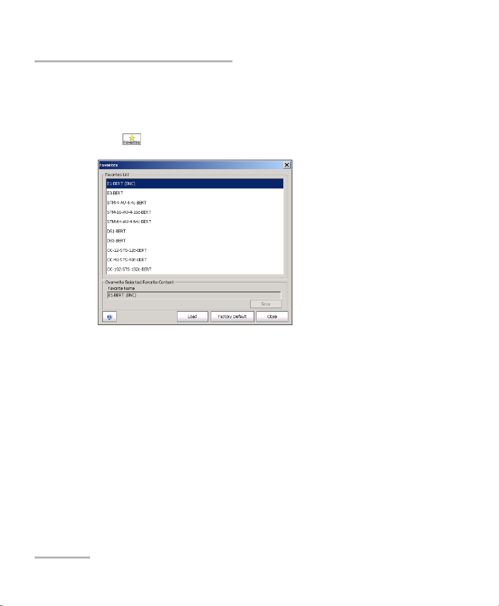
Favorites gives access to 10 factory test case configurations. Favorites is
available when no test is running.
Press .
Favorites List
Allows to select a test case configuration. The test case configuration
selected by default is the first one in the list.
Note: Test cases not supported by the current IQS-8100 Series model and its
options will not be created.
Note: Favorites may or may not be compatible from one version of software to
another. They also may or may not be compatible from one module to
another depending on the hardware and software option installed.
40 IQS-8100 Series Transport Blazer
Page 55

Introducing and Using the Graphical User Interface
Favorites
Overwrite Selected Favorite Content
The factory test case configurations can be modified as well as their
default names.
³ Favorite Name: Allows changing the name of the test case
configuration file. A maximum of 32 characters are allowed in the
name.
³ Save: Saves the current test case configuration using the specified
favorite name.
Load
Loads the selected test case configuration. Loading a favorite configuration
automatically clears the current test case.
Factory Default
Resets and regenerates the favorites list based on the module model and
its enabled options.
Note: A Default Favorites list is created the first time a specific module is used,
based on its module type and options. A favorites list is generated for each
module type used (IQS-8105, IQS-8115, IQS-8120, IQS-8120NG,
IQS-8120NGE, IQS-8130, IQS-8130NG, IQS-8130NGE, and IQS-8140). The
favorites list for a specific module type is common for all modules of the
same type on the IQS-600. The favorites list is not updated even when
either a new software option is installed or another module having
different options is used. For these reasons, the Factory Default button
allows to recreate the favorites list based on the current module and its
options.
SONET/SDH Application 41
Page 56
Introducing and Using the Graphical User Interface
Test Report Generation
Test Report Generation
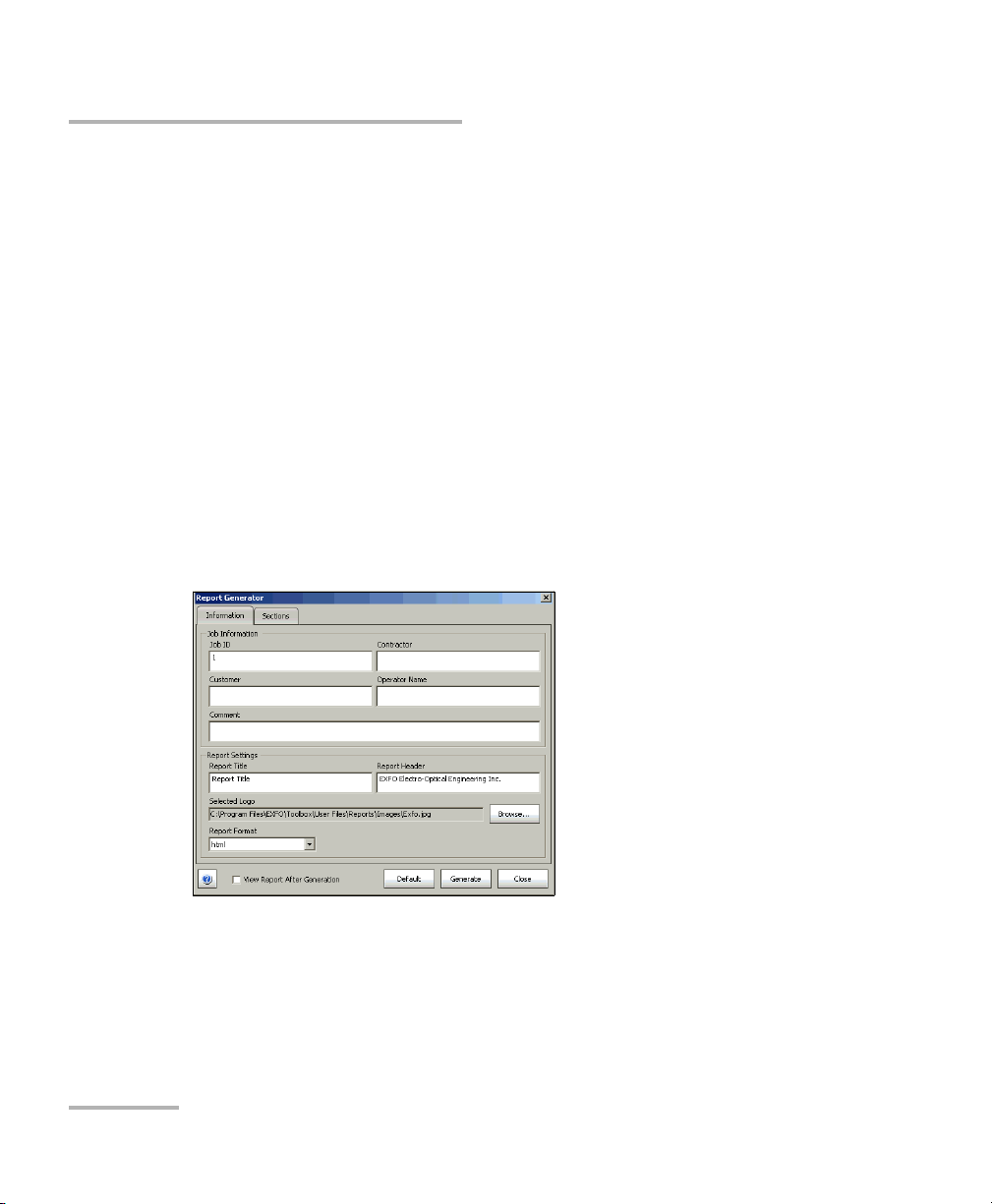
Press Report from the Global Test Status and Controls to generate a report
for the current test. The report contains all the information about the test
including the job information, system information, interface setup, test
summary, test configuration, results, etc.
Note: The Report button is not available while the test is running or the
SmartMode alarm scan is running.
Note: Nothing prevents the configuration and alarm/error injection setup while
the test has been stopped; thus, the report should be saved before changing
any test parameters to avoid discrepancy between the configuration and
results.
Information
³ Job Information: These parameters are used to identify the
source of the report and are not mandatory. Enter the following job
information if required: Job ID, Contractor, Customer, Operator
Name, and Comment. Up to 256 characters are allowed for each
parameter.
42 IQS-8100 Series Transport Blazer
Page 57

Introducing and Using the Graphical User Interface
Test R e p or t Gene r a t io n
³ Report Settings: These parameters are used to identify the report
and are not mandatory. Enter the following report information if
needed: Report Title, Report Header, Selected Logo, and Report
Format.
Press Browse to select a different logo, then press Open.
Report Format: Select the report file format. Choices are html, csv,
pdf, and txt. The CSV format (comma separated file format)
generates a report with comma delimiter for English OS and
semicolon for other OS languages. The default setting is html.
³ View Report After Generation: Allows displaying the report once
it is generated. However, the report can only be displayed when
the Windows application supporting the selected Report Format is
installed. The View Report After Generation check box is not
selected by default.
Note: Once generated, the report file can manually be opened typically using
Windows Explorer. The default directory is
d:\IQSManager\User Files\SonetSdhAnalyzerG2\Reports.
Note: If the html report contains special characters, please make sure that the
encoding in your Web browser is set to Western European ISO. To set the
encoding to Western European ISO, right press the report from Internet
Explorer, select Encoding, and select Western European ISO.
³ Default button: Press Default to restore the default report settings.
SONET/SDH Application 43
Page 58
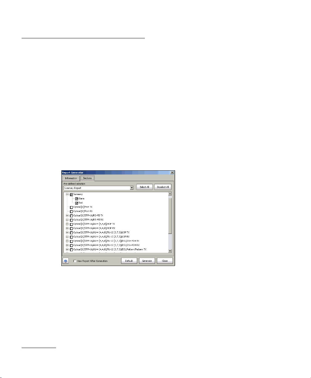
Introducing and Using the Graphical User Interface
Test Report Generation
³ Generate button: Allows generating and saving the report. Select
an existing file, or type a new name in the File name field and
press OK. The default directory is
d:\IQSManager\User Files\SonetSdhAnalyzerG2\Reports.
The report file can be saved on the following locations:
Local memory (IQS-600): The file is saved locally on the IQS-600
memory.
Network drive: The file is saved on a network drive.
USB drive or Compact Flash: The file is saved on a removable
drive.
Sections Tab
³ Pre-defined selection: Allows selecting the type of report, and the
window underneath allows selecting what will be part of the report.
The default setting is Summary Report. Choices are:
³ Summary Report selects the Summary report section only.
44 IQS-8100 Series Transport Blazer
Page 59
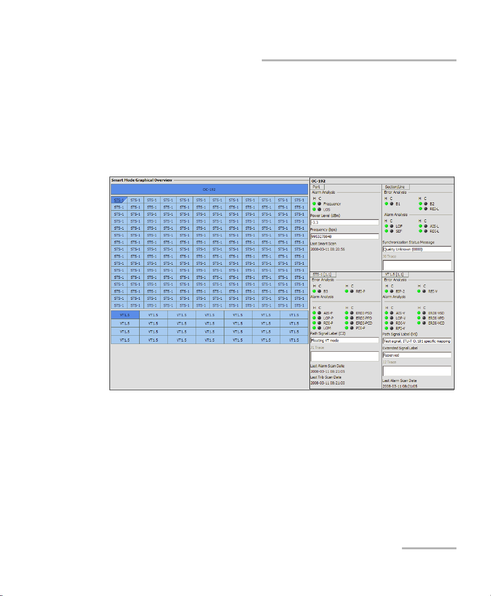
Introducing and Using the Graphical User Interface
Test R e p or t Gene r a t io n
³ SmartMode Report: Selects the SmartMode report section only.
SmartMode is not available on the IQS-8140. The Graphical
Overview under SmartMode provides a graphical view of the
SmartMode information. Graphical Overview is only available
when the Report Format from the Information tab is set to html
or pdf. The following picture shows an example of the SmartMode
Graphical Overview.
³ Test Case Report selects all the report sections.
Note: Once the report type is selected, each section can be selected to customize
the report.
The Select All and Deselect All buttons are used to respectively select
or deselect all the report sections.
SONET/SDH Application 45
Page 60
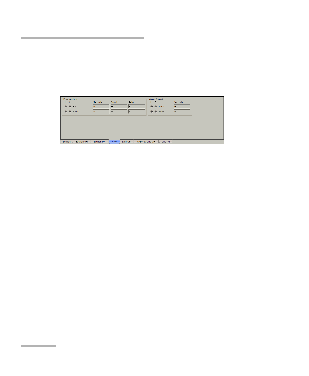
Introducing and Using the Graphical User Interface
Usual Tab Elements
Usual Tab Elements
Once the test is created, different tabs are available allowing test
configuration and monitoring. The following section describes usual
elements appearing on those tabs.
Status LEDs
³ H (History) LED: Indicates that alarms/errors occurred in the past. A
grey LED indicates that the test did not run yet, a green LED indicates
that no alarm/error has occurred, while a red LED indicates that at
least one alarm/error has occurred in the test.
³ C (Current) LED: Gives the current status of the alarm/error. A grey LED
indicates that the test is not running, a green LED indicates that there is
no alarm/error, while a red LED indicates that at least one alarm/error
condition has occurred in the last second.
Note: The H and C LEDs are updated every second.
46 IQS-8100 Series Transport Blazer
Page 61

Introducing and Using the Graphical User Interface
Alarm/Error Measurements
Note: Alarms/Errors are only monitored once the test is started.
³ Seconds: Gives the total number of the seconds in which one or more
alarm/error occurred.
³ Count: Gives the number of occurrences of a specific error. The count
is displayed using integer value; exponential value (1.00000E10) is used
when the count is bigger than the field display capacity.
³ Rate: Calculates and displays the error rate. The rate is expressed using
the exponential format with two decimal digits (example: 1.23E-04).
³ Percentage values are expressed using one decimal digit.
(example: 9.9%).
³ Alphanumeric values display the extended ASCII character set
including the ITU T.50 Characters on page 57. For Trace Messages using
64-bytes format, the last 2 bytes, Carriage Return and Line Feed, will be
displayed within brackets (<cr> and <lf>).
Usual Tab Elements
Arrow Buttons
Button Description
Top arrow: Moves to the top of the list.
Page up arrow: Moves one page up.
Up arrow: Moves one row up.
Down arrow: Moves one row down.
Page down arrow: Moves one page down.
End arrow: Moves to the end of the list.
SONET/SDH Application 47
Page 62
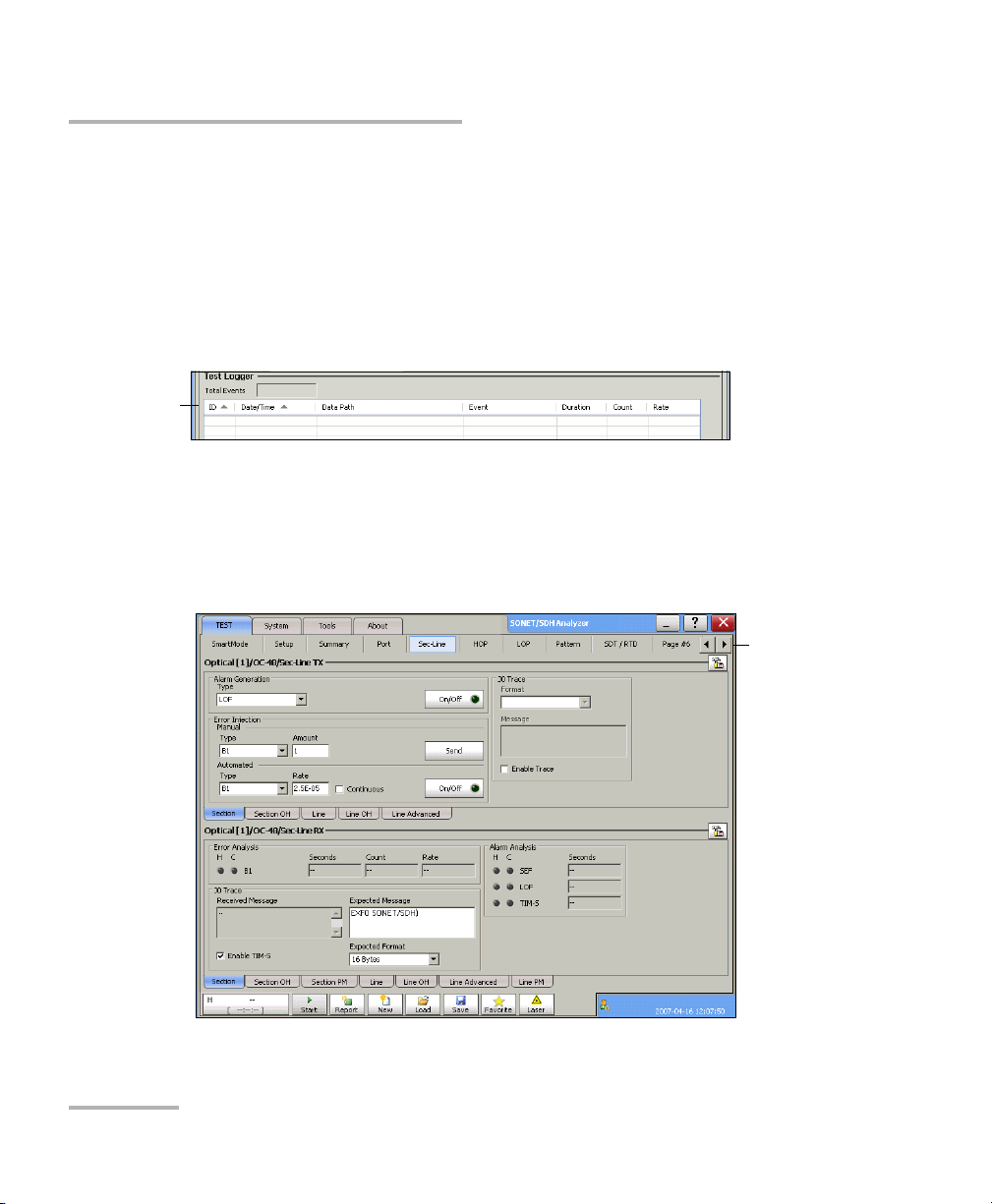
Introducing and Using the Graphical User Interface
Usual Tab Elements
Table Sorting
Tables offer sorting capabilities on one or more columns.
An arrow next to the column label name, indicates the sorting column field
and the sorting order. Pressing again on the selected sort column label will
change the sort order.
Pressing another column label allows to sort using a different field.
Tab l e So r t
Left and Right Scroll Buttons
Left and right scroll buttons are used to respectively move left and right
allowing to see more tabs. The left and right scroll buttons are not always
displayed; they are only displayed when required.
Left and
Right scroll
buttons
48 IQS-8100 Series Transport Blazer
Page 63
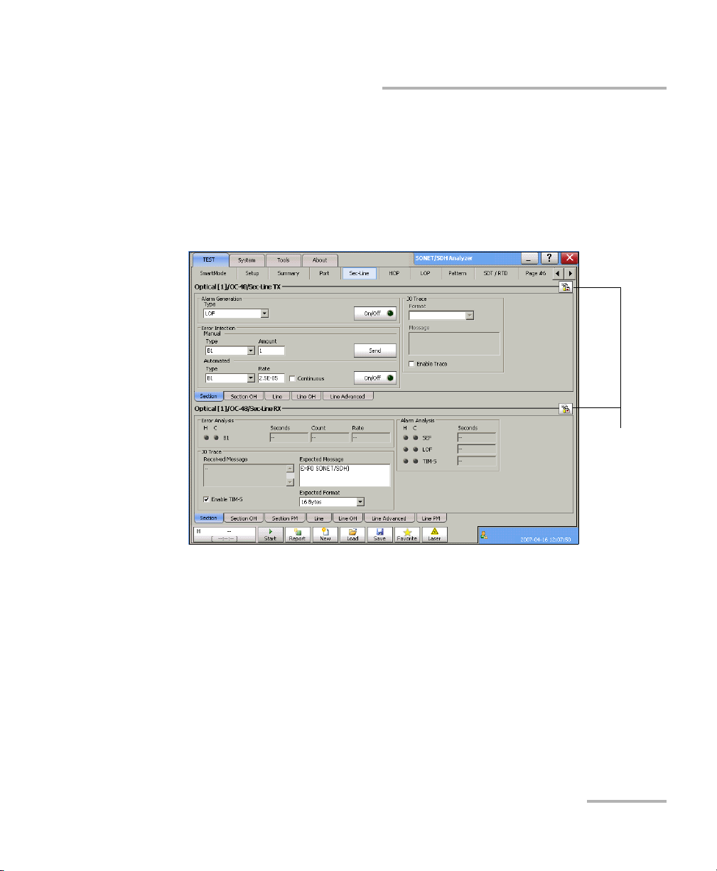
Introducing and Using the Graphical User Interface
Tab Configuration
Tab Configuration
Once the test is created, other tabs next to the Test tabs are enabled
allowing configuration of test parameters and viewing of the test status and
results.
A tab configuration button is available at the top-right part of each tab.
Configuration
Ta b
buttons
SONET/SDH Application 49
Page 64

Introducing and Using the Graphical User Interface
Tab Configuration
This tab configuration window allows configuration of all tabs on any page
except for the SmartMode, Tes t Setup , and Summary tabs. The tab
configuration allows also to jump directly to the desired page by selecting it
from the Defined Tabs list and then pressing OK.
Selected Tab
³ Tab N a me indicates the name of the tab containing the two tabs (top
and bottom page). Pressing this field allows changing the tab name.
Tab name can be up to 35 characters long including the “/” and spaces.
³ Top Pag e indicates the tab displayed at the top of the tab.
³ Bottom Page indicates the tab displayed at the bottom of the tab.
50 IQS-8100 Series Transport Blazer
Page 65

Introducing and Using the Graphical User Interface
Tab Configuration
Defined Tabs
Allows the selection of a tab.
Up and down arrows are used to respectively move the selected page up
or down in the list.
Insert button allows the insertion of a new tab after the selected tab (the
one highlighted) A maximum of 30 tabs can be displayed.
Delete button allows the deletion of the selected tab.
Page Selection
³ Typ e: Allows the selection of a tab that will be assigned to the selected
tab when pressing either Apply to top page or Apply to bottom page.
³ Path: Indicates the test signal structure (layers/nodes of the test case)
corresponding to the selected tab. Refer to Supported Paths/Mappings
on page 59 for more information on test layers/nodes.
³ Apply To Top Page: Applies the selected tab as top of page for the
selected tab.
³ Apply To Bottom Page: Applies the selected tab as bottom of page for
the selected tab.
Note: The available tabs listed are a function of the test path activated. Empty
Ta b displays a blank tab (Tabs that are not populated are left blank).
SmartMode, Tes t S e tu p, and Summary tabs cannot be duplicated,
deleted, or renamed.
SONET/SDH Application 51
Page 66

Introducing and Using the Graphical User Interface
Tab Configuration
Help Button (?)
Displays the help information related to the tab configuration. It is also
possible to navigate through the remainder of the help information.
Default Button
Return to the default page configuration layout.
OK Button
Accepts the page layout changes and jumps to the selected page (Defined
tabs).
Cancel Button
Cancels the changes and returns to the page from where the tab
configuration was launched.
52 IQS-8100 Series Transport Blazer
Page 67

Introducing and Using the Graphical User Interface
Keyboard Usage
Keyboard Usage
The GUI pops up different keyboards to modify data. Following are the
usual keyboard keys:
³ Left arrow: Moves the cursor one position to the left.
³ Right arrow: Moves the cursor one position to the right.
³ Del: Deletes the value at the cursor position.
³ Back: Deletes the value preceding the cursor position.
³ Help: Displays the help information related to the keyboard usage.
It is also possible to navigate through the help information.
³ OK and Enter: Completes data entry.
³ Cancel: Closes the keyboard and discards the keyboard entry.
³ Binary keyboard: Allows entering 0 and 1 values.
SONET/SDH Application 53
Page 68

Introducing and Using the Graphical User Interface
Keyboard Usage
³ Numerical keyboards: Allows entering integer/decimal values.
³ For integer unsigned or signed values.
³ For rate values: Allows entering the rate values (0 through 9, and
exponent).
54 IQS-8100 Series Transport Blazer
Page 69
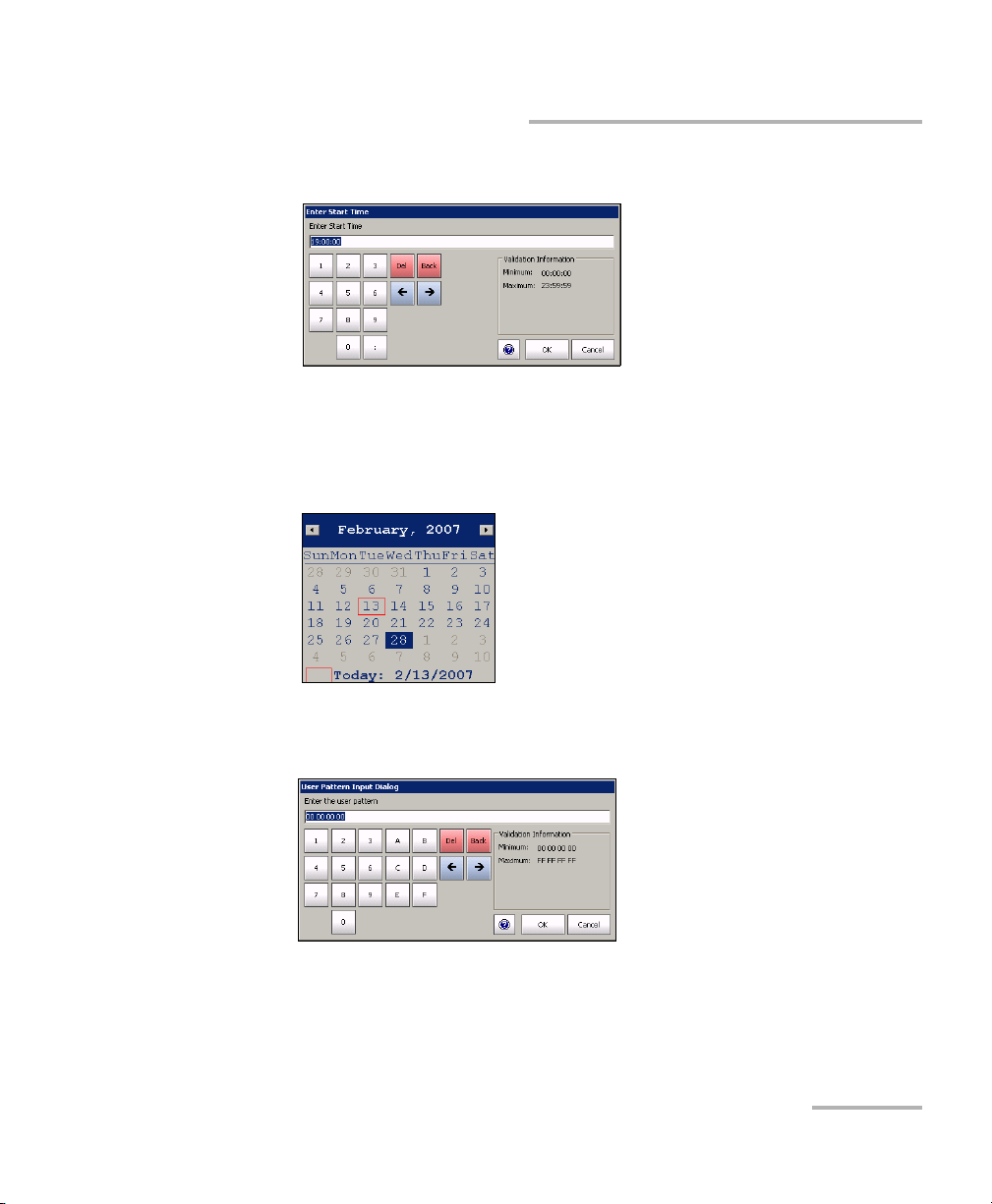
Introducing and Using the Graphical User Interface
Keyboard Usage
³ Time Keyboard: Allows entering a time value.
³ Date keyboard: Allows selecting a date by pressing the date on the
calendar. Use the left and right arrow to switch from one month to
another or press the month area for quick month selection. Press the
year area for quick year selection.
³ Hexadecimal keyboards: Allows entering hexadecimal values
(0 through 9 and A through F)
SONET/SDH Application 55
Page 70

Introducing and Using the Graphical User Interface
Keyboard Usage
³ Full keyboard: Allows entering numbers, letters and some other
characters. The Back, Del, Shift and space bar keys have the same
functionality as a regular PC keyboard.
³ Trace message keyboard Allows entering alphanumerical characters
(ITU T.50) required for TTI, FTFL, J0, J1, and J2 Trace fields. Press the
Ctrl Char button to access these characters.
56 IQS-8100 Series Transport Blazer
Page 71

Introducing and Using the Graphical User Interface
Keyboard Usage
ITU T.50 Characters
b7 to b1 Character Description b7 to b1 Character Description
000 0000 NUL Null 001 0000 DLE Data Link Escape
000 0001 SOH Start Of Heading 001 0001 DC1 Device Control 1
000 0010 STX Start of Text 001 0010 DC2 Device Control 2
000 0011 ETX End of Text 001 0011 DC3 Device Control 3
000 0100 EOT End Of Transmission 001 0100 DC4 Device Control 4
000 0101 ENQ Enquiry 001 0101 NAK Negative
Acknowledge
000 0110 ACK Acknowledge 001 0110 SYN Synchronous idle
000 0111 BEL Bell 001 0111 ETB End of Transmission
Block
000 1000 BS Backspace 001 1000 CAN Cancel
000 1001 HT Horizontal
001 1001 EM End of Medium
Tab ul at io n
000 1010 LF Line Feed 001 1010 SUB Substitute character
000 1011 VT Vertical Tabulation 001 1011 ESC Escape
000 1100 FF Form Feed 001 1100 IS4 Information
Separator 4
000 1101 CR Carriage Return 001 1101 IS3 Information
Separator 3
000 1110 SO Shift-Out 001 1110 IS2 Information
Separator 2
000 1111 SI Shift-In 001 1111 IS1 Information
Separator 1
SONET/SDH Application 57
Page 72

Page 73

6 Creating and Starting a Test
Case
A test case can be created using one of the following methods:
³ SmartMode allows signal discovery and alarm/error monitoring. The
test can be created according to the detected signal structure.
SmartMode is only available for SONET/SDH signals (Not supported on
the IQS-8140). See Creating and Starting a Test Case Using SmartMode
on page 122.
³ Test S e tup allows the creation of the test case by travelling through the
signal structure. See Introducing the Test Setup on page 62.
³ Favorites allows setting up the test case by selecting a predefined test
configuration. Refer to Favori tes on page 40.
³ Load Configuration allows setting up the test case by loading a
previously saved configuration. Refer to Load from the Global Test
Status and Controls on page 35.
³ Script allows running a script that creates the test case. Refer to Script
Tab on page 551.
Note: Once the test case is created, press the Start button to start the test. Refer to
Global Test Status and Controls on page 35 for more information on test
management.
Supported Paths/Mappings
The supported test paths/mappings are presented in the following charts
and depend on modules and enabled options. Optical interfaces are not
supported on the IQS-8105.
SONET/SDH Application 59
Page 74

Creating and Starting a Test Case
Supported Paths/Mappings
OTN/SONET/DSn Interface Path/Mapping
60 IQS-8100 Series Transport Blazer
Page 75
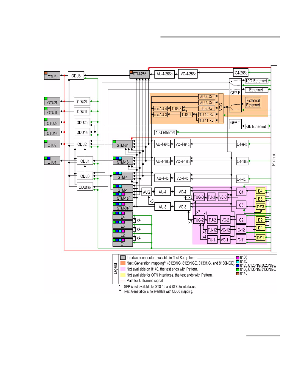
Creating and Starting a Test Case
Supported Paths/Mappings
OTN/SDH/PDH Interface Path/Mapping
SONET/SDH Application 61
Page 76
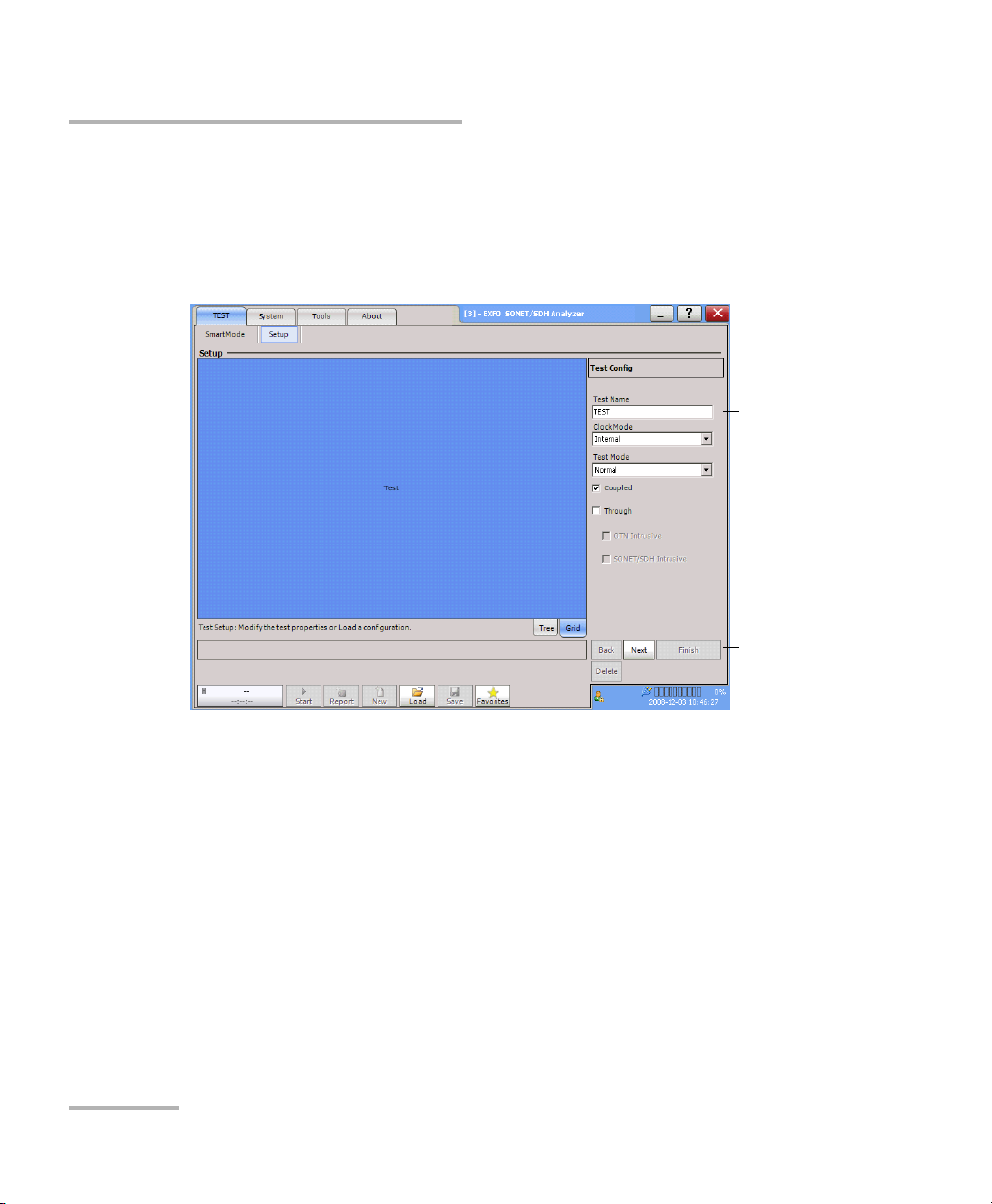
Creating and Starting a Test Case
Introducing the Test Setup
Introducing the Test Setup
The Test S et up window allows the creation of the test case by navigating
through the signal structure. In the case where the GUI is not in the setup
window, select the Setup tab from the TEST Tab (refer to 30).
Configuration
section
Data Path
Selector
³ Tree tab allows seeing the configuration test structure (data path).
³ Grid tab is used for timeslot selection or test case direction (decoupled
Tes t S et u p
Controls
test mode).
³ Data Path Selector is used for the selection of each node (for
example: port, signal, tributary, VCG, GFP, Pattern) of the test case.
³ Configuration section allows parameters configuration for each node
of the test.
Test N ame represents the name of the test. The default setting is TEST.
62 IQS-8100 Series Transport Blazer
Page 77

Creating and Starting a Test Case
Introducing the Test Setup
³ Test S etup Co ntr o ls:
³ Back returns to the previous configuration step allowing to see,
change or delete what had been selected.
³ Next switches to the next configuration step. The Next button is
only available when selection(s) from the Data Path Selector
and/or the Grid tab has been made.
³ Delete deletes the current path node.
³ Finish/Setup:
Finish completes the configuration and creates the test case.
Default parameters will be used for the remaining wizard steps.
Thus, pressing Finish will automatically add a pattern at the end of
the test case structure if not already selected.
Setup is displayed instead of Finish once the test is created
allowing to return in setup mode. Setup is not available when the
test is started (running).
The test path is created through the configuration of each layer that must
be crossed by the signal under test. The test path contains the following
nodes:
For example:
Test Connector Signal
Normal Coupled
Optical OC-192, Normal, STS-1
Timeslot 1, VT1.5 Timeslot 1,
Payload/Traffic
Pattern
DS1
SONET/SDH Application 63
Page 78

Creating and Starting a Test Case
Introducing the Test Setup
³ The Test node is the root of the test case. It allows the configuration of
the test name, clock mode and test mode.
³ The Connector node allows the selection and configuration of the
physical port.
³ The Signal node allows the selection and configuration of the signal.
Additional signal nodes are created for each step of the mapped signal
level.
³ The Payload/Traffic node completes the test path by selecting the
pattern or an external traffic such as Ethernet interface with Packet
Blazer.
64 IQS-8100 Series Transport Blazer
Page 79

Creating and Starting a Test Case
Typical Tes t C a s e s
Typical Test Cases
The remaining of this chapter describes how to create the following typical
DSn/PDH, SONET/SDH, OTN, Next Generation, and Ethernet over OTN test
cases. The availability of test cases depend on the module and activated
options.
³ Creating an Electrical DSn/PDH Test Case in Normal Mode
(IQS-8105/15/20/30) on page 66
³ Creating an Electrical DS1 or DS3 Test Case in Dual RX Mode
(IQS-8105/15/20/30) on page 71
³ Creating an Electrical DS1 Test Case in NI/CSU Emulation Mode
(IQS-8105/15/20/30) on page 75
³ Creating an Electrical SONET/SDH Test Case on page 79
³ Creating an Optical SONET/SDH Test Case (IQS-8115/20/30) on page 83
³ Creating an Optical SONET/SDH Test Case on an IQS-8140 on page 87
³ Creating an Optical SONET/SDH/OTN Multi-Channel SDT Test Case
(IQS-8120/8130/8140) on page 91
³ Creating an OTN (OTU1 and OTU2) Test Case on page 92
³ Creating an OTN (OTU3) Test Case on page 97
³ Creating a Next Generation Test Case including VCAT/LCAS and GFP on
page 103
³ Creating an OTN Overclocked (OTU1e/OTU2e/OTU1f/OTU2f) Test Case
(IQS-8130, IQS-8130NG, and IQS-8130NGE) on page 108.
SONET/SDH Application 65
Page 80
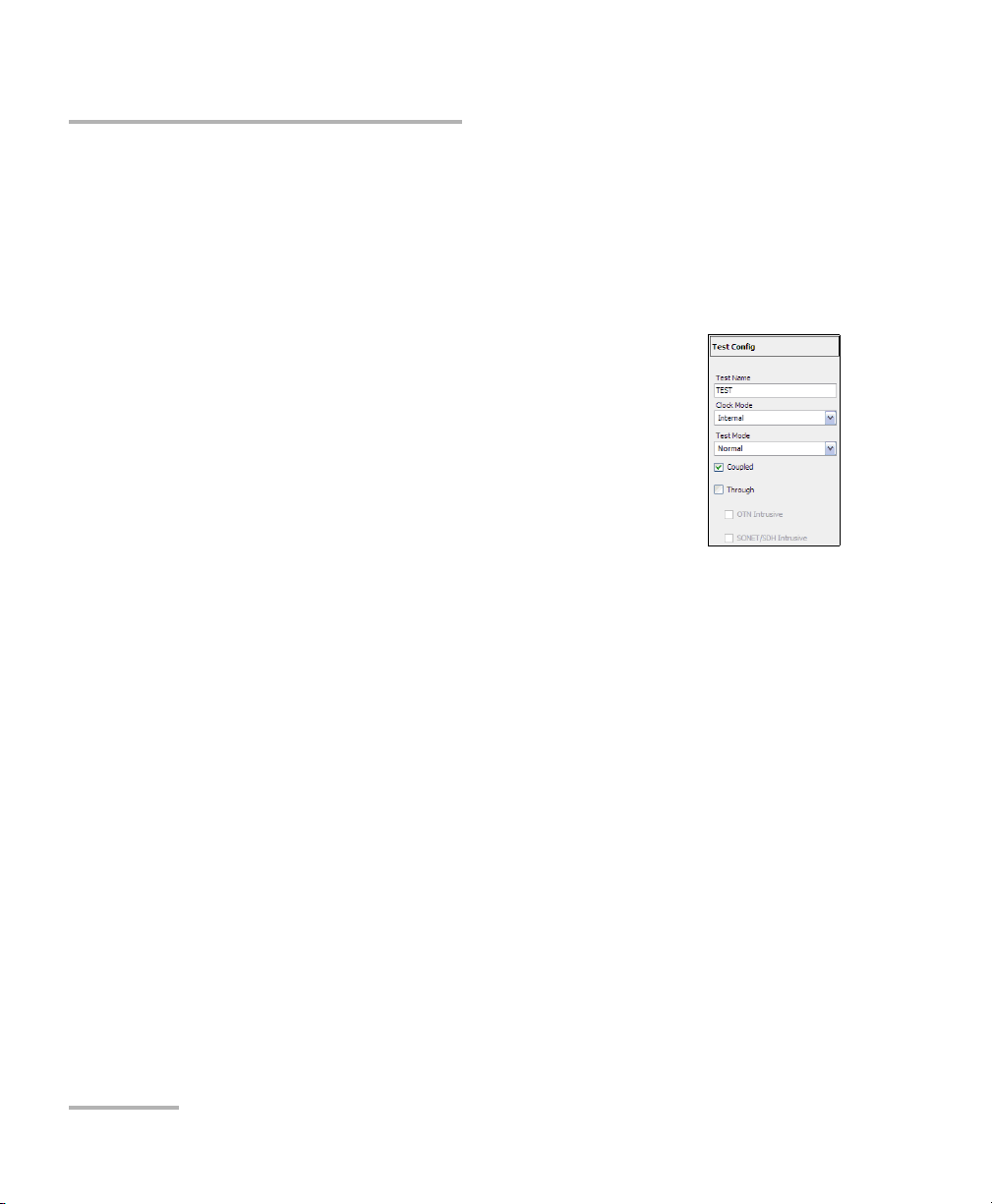
Creating and Starting a Test Case
Typic a l Tes t Cases
Creating an Electrical DSn/PDH Test Case in Normal
Mode (IQS-8105/15/20/30)
The following procedures describe the creation of an electrical DSn/PDH
test case in Normal mode.
To create an Electrical DSn/PDH Test in Normal mode:
1. Test configuration:
1a. Select the source Clock Mode that will be used
for the test. Refer to Clock Configuration on
page 129 for more information.
1b. Select Normal as the Te s t Mod e. Refer to Test
Configuration on page 126 for more
information.
1c. Select the Coupled check box to set the same
settings for both the TX and RX signals or clear the Coupled
check box to configure the TX and RX signal individually
(decoupled).
1d. Select the Through check box to loop the RX signal to the TX port.
The Clock Mode is automatically set to Recovered when the
Through check box is selected.
1e. Leave the SONET/SDH Intrusive and OTN Intrusive check boxes
cleared.
1f. Press Next.
66 IQS-8100 Series Transport Blazer
Page 81

2. Interface connector selection:
2a. From the data path
selector, press the
desired electrical interface connector.
BNC for DS3, E4, E3, E2, and E1.
Bantam for DS1and E1.
RJ-48c for DS1 and E1.
2b. For Decoupled test
mode, both TX and
RX ports have to be
selected and
configured:
First select the
interface type for
TX from the data
path selector then
proceed with the
rest of the test setup steps to set the test parameters for the TX
interface. At the end, do not press Finish yet. Press Back to return
to the RX/TX selection screen and select the interface type for RX
from the data path selector then proceed with the rest of the test
setup steps to set the test parameters for the RX interface.
Creating and Starting a Test Case
Typical Tes t C a s e s
2c. Press Next.
SONET/SDH Application 67
Page 82
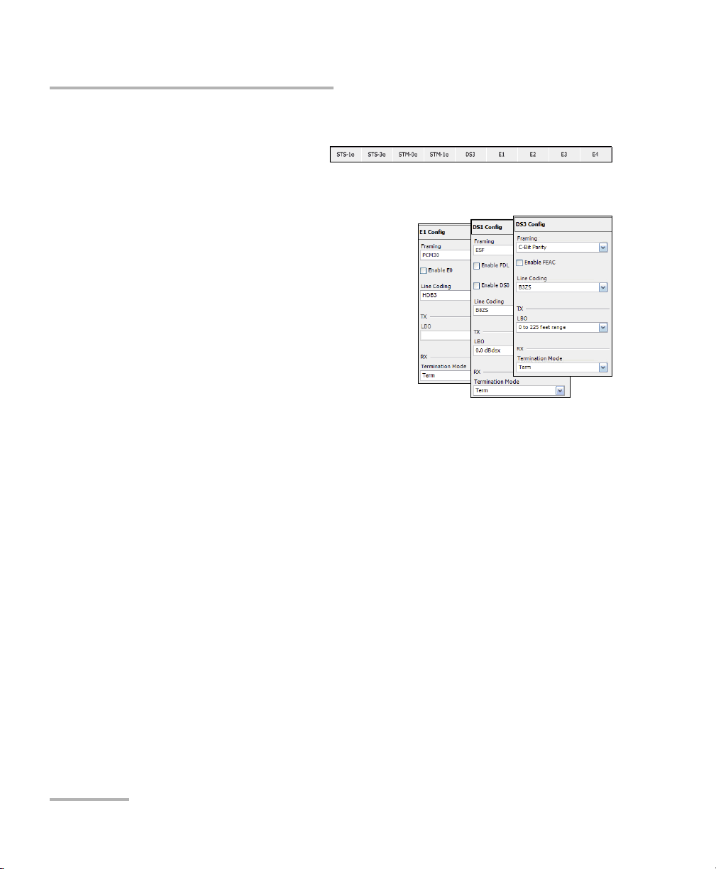
Creating and Starting a Test Case
Typic a l Tes t Cases
3. Interface selection and configuration:
3a. Press the desired
interface: DS3,
DS1, E4, E3, E2, or E1.
3b. Select the Framing, Line
Coding, TX LBO (DSn interface
only), and RX Termination
Mode. Term , Mon, and Bridge
(DS1/E1 only) termination mode
are available. For more
information, refer to TX - DSn
Tab s on page 269 or PDH Tabs on
page 369 for the framing, Port T X
(Electrical Interfaces) on
page 138 for Line Coding and
LBO, to RX - DSn Tabs on page 269 or PDH Tabs on page 369 for
Termination Mode.
3c. For DS1, sele c t t he Enable FDL check box to allow facility data
link testing.
3d. For DS1/E1, select the Enable DS0/E0 check box to allow DS0 or
E0 testing.
3e. For DS3 interface, select the Enable FEAC check box to allow far
end alarm and control testing.
3f. Press Next or Finish.
68 IQS-8100 Series Transport Blazer
Page 83

Creating and Starting a Test Case
4. Select the test
path/mapping (For DS3,
E4, E3, and E2).
4a. From the data path
selector, press the
desired mapping
then press the
timeslot from the
Grid tab. Choices
depend on the
selected interface.
See Supported
Paths /M app ing s on
page 59 for more information.
4b. Select the Framing. For more
information, refer to DSn Tabs on
page 269 or PDH Tabs on page 369.
4c. For DS1, sele c t t he Enable FDL check
box to allow facility data link testing. For
Dual RX test, FDL is only available for the primary DS1 TX/RX port.
Typical Tes t C a s e s
4d. For DS1/E1, select the Enable DS0/E0 check box to allow DS0 or
E0 testing.
4e. For Pattern, go to step 5.
4f. Press Next or Finish.
4g. Repeat step 4 as required to complete the path/mapping. See
Supported Paths/Mappings on page 59 for more information.
5. Pattern Configuration:
5a. Set the pattern parameters. Refer to Pattern TX
on page 405 and Patter n R X on page 409 for
more information.
SONET/SDH Application 69
Page 84

Creating and Starting a Test Case
Typic a l Tes t Cases
6. Press Finish to complete the test setup. The Grid tab closes and
automatically switch to the Alarm summary tab.
7. For additional configuration parameters and results, refer to Summary
Tab s on page 125, Port Tabs on page 137, DSn Tabs on page 269, PDH
Tab s on page 369, BERT Tabs on page 405, Advanced Tabs on
page 411, and Common Tabs on page 491.
8. Press the Start button to start the test. Refer to Global Test Status and
Controls on page 35 for more information on test management.
70 IQS-8100 Series Transport Blazer
Page 85

Creating and Starting a Test Case
Typical Tes t C a s e s
Creating an Electrical DS1 or DS3 Test Case in Dual
RX Mode (IQS-8105/15/20/30)
The following procedures describe the creation of an electrical DS1 or DS3
test case in Dual RX mode.
To create an Electrical DS1 or DS3 Test in Dual RX mode:
1. Test configuration:
1a. Select the source Clock Mode that will be used
for the test. Refer to Clock Configuration on
page 129 for more information.
1b. Select Dual RX (DS1 or DS3 signals) as the Te st
Mode. Refer to Test Configuration on page 126
for more information.
The Coupled check box is automatically
selected for Dual RX mode meaning that the settings for both the
TX and RX signals are the same.
1c. Press Next.
2. Interface connector selection:
2a. From the data path selector, press the desired electrical interface
connector.
BNC for DS3, Bantam or RJ-48c for DS1.
2b. Press Next.
SONET/SDH Application 71
Page 86

Creating and Starting a Test Case
Typic a l Tes t Cases
3. Interface configuration:
3a. Select the Framing, Line Coding, TX
LBO, and RX Termination Mode. Ter m,
Mon, and Bridge (DS1 only) termination
modes are available. For more
information, refer to TX - DSn Tabs on
page 269 or PDH Tabs on page 369 for the
framing, Port TX (Electrical Interfaces) on
page 138 for Line Coding and LBO, or RX
DSn Tabs on page 269.
3b. Select the Ter mina t ion M ode for both
RX ports. Dual RX test case uses the BNC
labelled AUX for the second RX port.
3c. For DS1, sele c t t he Enable FDL check box to
allow facility data link testing.
3d. For DS1/E1, select the Enable DS0/E0 check
box to allow DS0 or E0 testing.
3e. For DS3 interface, select the Enable FEAC
check box to allow far end alarm and control
testing.
3f. Press Next or Finish.
72 IQS-8100 Series Transport Blazer
Page 87

Creating and Starting a Test Case
4. For DS3, select the test
path/mapping.
4a. From the data path
selector, press the
desired mapping
then press the
timeslot from the
Grid tab. Choices
depend on the
selected interface.
See Supported
Paths /M app ing s on
page 59 for more
information.
4b. Select the Framing. For more
information, refer to DSn Tabs on
page 269.
4c. For DS1, sele c t t he Enable FDL check
box to allow facility data link testing.
FDL is only available for the main DS1 TX/RX port.
Typical Tes t C a s e s
4d. For DS1, s e l ec t th e Enable DS0/E0 check box to allow DS0 or E0
testing.
4e. For Pattern, go to step 5.
4f. Press Next or Finish.
4g. Repeat step 4 as required to complete the path/mapping. See
Supported Paths/Mappings on page 59 for more information.
5. Pattern Configuration:
5a. Set the pattern parameters. Refer to Pattern TX
on page 405 and Patter n R X on page 409 for
more information.
SONET/SDH Application 73
Page 88

Creating and Starting a Test Case
Typic a l Tes t Cases
6. Press Finish to complete the test setup. The Grid tab closes and
automatically switch to the Alarm summary tab.
7. For additional configuration parameters and results, refer to Summary
Tab s on page 125, Port Tabs on page 137, DSn Tabs on page 269, PDH
Tab s on page 369, BERT Tabs on page 405, Advanced Tabs on
page 411, and Common Tabs on page 491.
8. Press the Start button to start the test. Refer to Global Test Status and
Controls on page 35 for more information on test management.
74 IQS-8100 Series Transport Blazer
Page 89

Creating and Starting a Test Case
Typical Tes t C a s e s
Creating an Electrical DS1 Test Case in NI/CSU
Emulation Mode (IQS-8105/15/20/30)
The following procedures describe the creation of an electrical DS1 test
case in NI/CSU Emulation mode.
To create an Electrical DS1 Test in NI/CSU Emulation mode:
1. Test configuration:
1a. Select NI/CSU Emulation as the Tes t M ode:
Normal. Refer to Test Configuration on page 126
for more information. The Coupled check box
must be selected to allow NI/CSU Emulation
mode selection.
The Clock Mode is automatically set to
Recovered. Refer to Clock Configuration on
page 129 for more information.
1b. Press Next.
2. Interface connector selection:
2a. From the data path selector, press the desired electrical interface
connector: Bantam or RJ-48c.
2b. Press Next.
SONET/SDH Application 75
Page 90
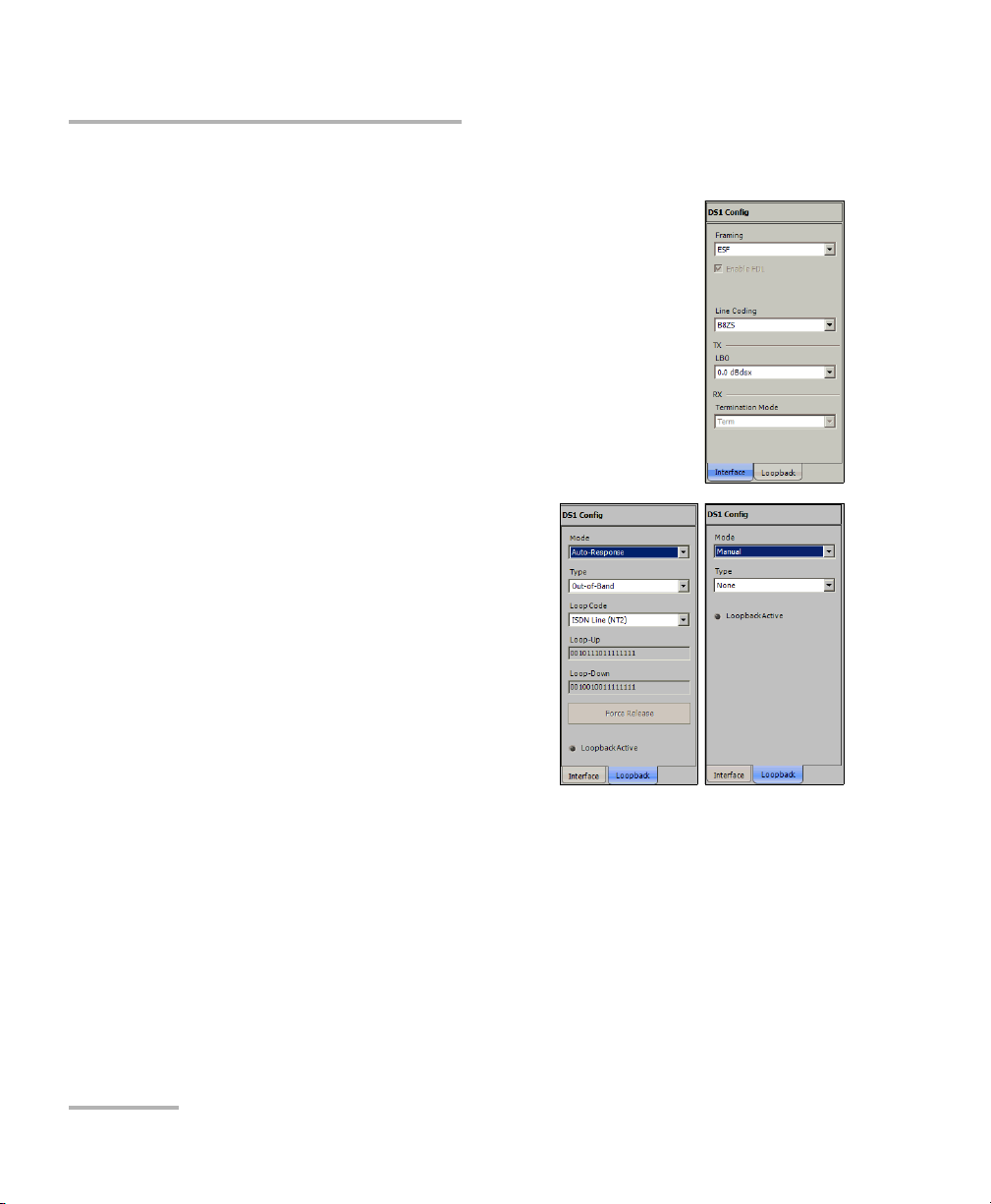
Creating and Starting a Test Case
Typic a l Tes t Cases
3. Interface configuration:
3a. From the Interface tab, select the Framing,
Line Coding, and TX LBO.
The RX Termination Mode is set to Term .
For more information, refer to DS1/1.5M TX on
page 275 for the framing, Por t TX (Elec t rical
Interfaces) on page 138 for Line Coding and
LBO, and to DS1/1.5M RX on page 278 for
Termination Mode.
Enable FDL check box is automatically
selected to allow facility data link testing.
3b. From the Loopback tab, select
the loopback control Mode:
Manual or Auto-Response.
3c. For Manual:
Select the Type of loopback
code that will be applied:
None, Line, or Payload.
Payload is only available with
SF and ESF framings.
The Loopback Active LED
indicates the presence of an
active loopback.
3d. For Auto-Response:
Select the Type of loopback code on which the module will
respond: In-Band or Out-of-Band. Out-of-Band is only available
when the interface framing is set to ESF.
76 IQS-8100 Series Transport Blazer
Page 91
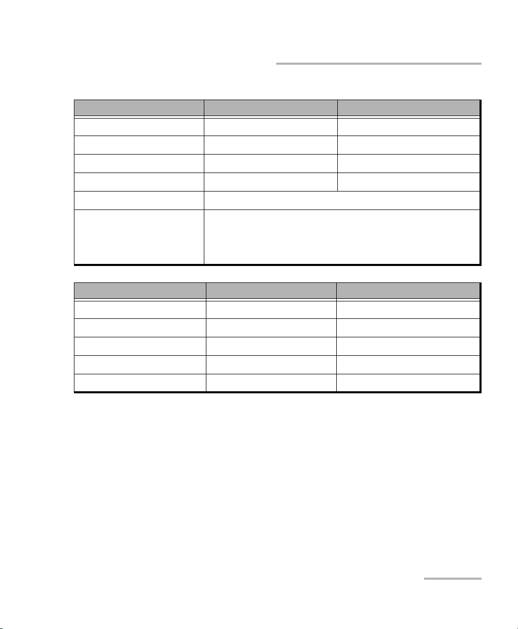
Creating and Starting a Test Case
Typical Tes t C a s e s
Select the Loop Code:
In-Band loop code Loop-UP Code Loop-Down Code
CSU 10000 100
NIU FAC1 1100 1110
NIU FAC2 11000 11100
NIU FAC3 100000 100
Loop Code1 to 10 Refer to DSn Loop Codes on page 543 for more information.
User Defined Loop-Up and Loop-Down range is from 000 to
1111111111111111. The default DS1 loop codes
correspond to the DS1 In-Band loop codes
(Loop-Up=10000, and Loop-Down=100).
Out-of-Band loop code Loop-UP Code Loop-Down Code
Line 00001110 11111111 00111000 11111111
Payload 00010100 11111111 00110010 11111111
Reserved For Network Use 00010010 11111111 00100100 11111111
ISDN Line (NT2) 00101110 11111111 00100100 11111111
CI/CSU Line(NT1) 00100000 11111111 00100100 11111111
The Loop-UP and Loop-Down values are automatically updated
to the In-Band or Out-of-Band selection (Type). However these
fields are editable when the Loop Code is set to User Defined.
The Force Release button allows to release a loopback condition
initiated from the network. Only available when a loopback is
active.
The Loopback Active LED indicates the presence of an active
loopback.
3e. Press Next or Finish.
SONET/SDH Application 77
Page 92

Creating and Starting a Test Case
Typic a l Tes t Cases
4. Press Finish to complete the test setup.
The DS1 Loopback function is now operational; no need to start the
test. However, the test may be started to monitor the condition of the
DS1 line connection to that test equipment.
5. For additional configuration parameters and results, refer to Summary
Tab s on page 125, Port Tabs on page 137, and DSn Tabs on page 269.
6. For additional configuration parameters and results, refer to the
following chapters: Summary, Port, and DSn tabs.
7. Press the Start button to start the test. Refer to Global Test Status and
Controls on page 35 for more information on test management.
78 IQS-8100 Series Transport Blazer
Page 93
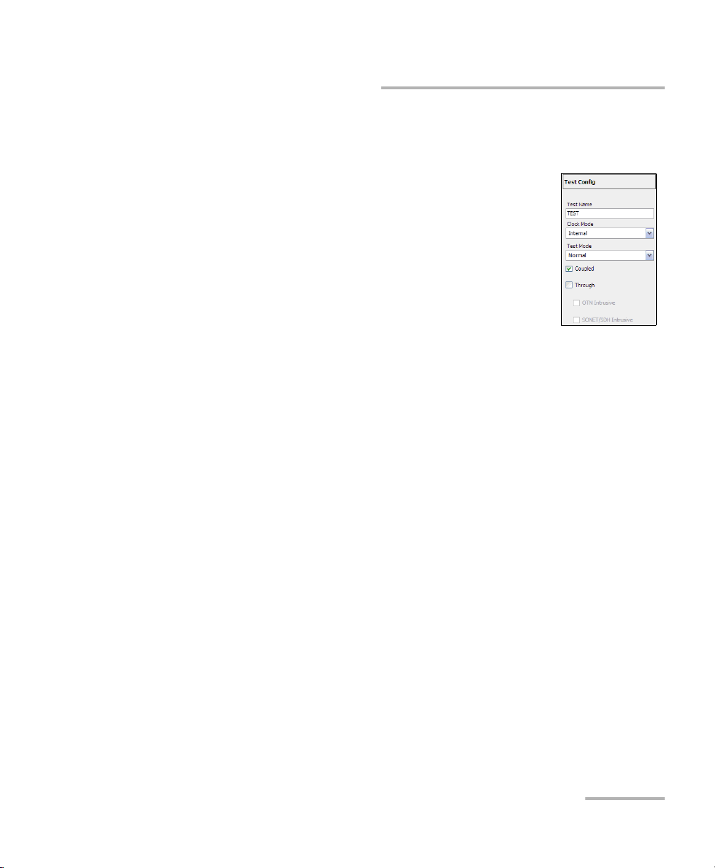
Creating and Starting a Test Case
Typical Tes t C a s e s
Creating an Electrical SONET/SDH Test Case
To create an Electrical SONET/SDH Test on an IQS-8105/15/20/30:
1. Test configuration:
1a. Select the source Clock Mode that will be used
for the test. Refer to Clock Configuration on
page 129 for more information.
1b. Select Normal as the Te s t Mod e. Refer to Test
Configuration on page 126 for more
information.
1c. Select the Coupled check box to set the same
settings for both the TX and RX signals or clear the Coupled
check box to configure the TX and RX signal individually
(decoupled).
1d. Select the Through check box to loop the RX signal to the TX port.
The Clock Mode is automatically set to Recovered when the
Through check box is selected.
1e. Leave the SONET/SDH Intrusive and OTN Intrusive check boxes
cleared.
1f. Press Next.
SONET/SDH Application 79
Page 94
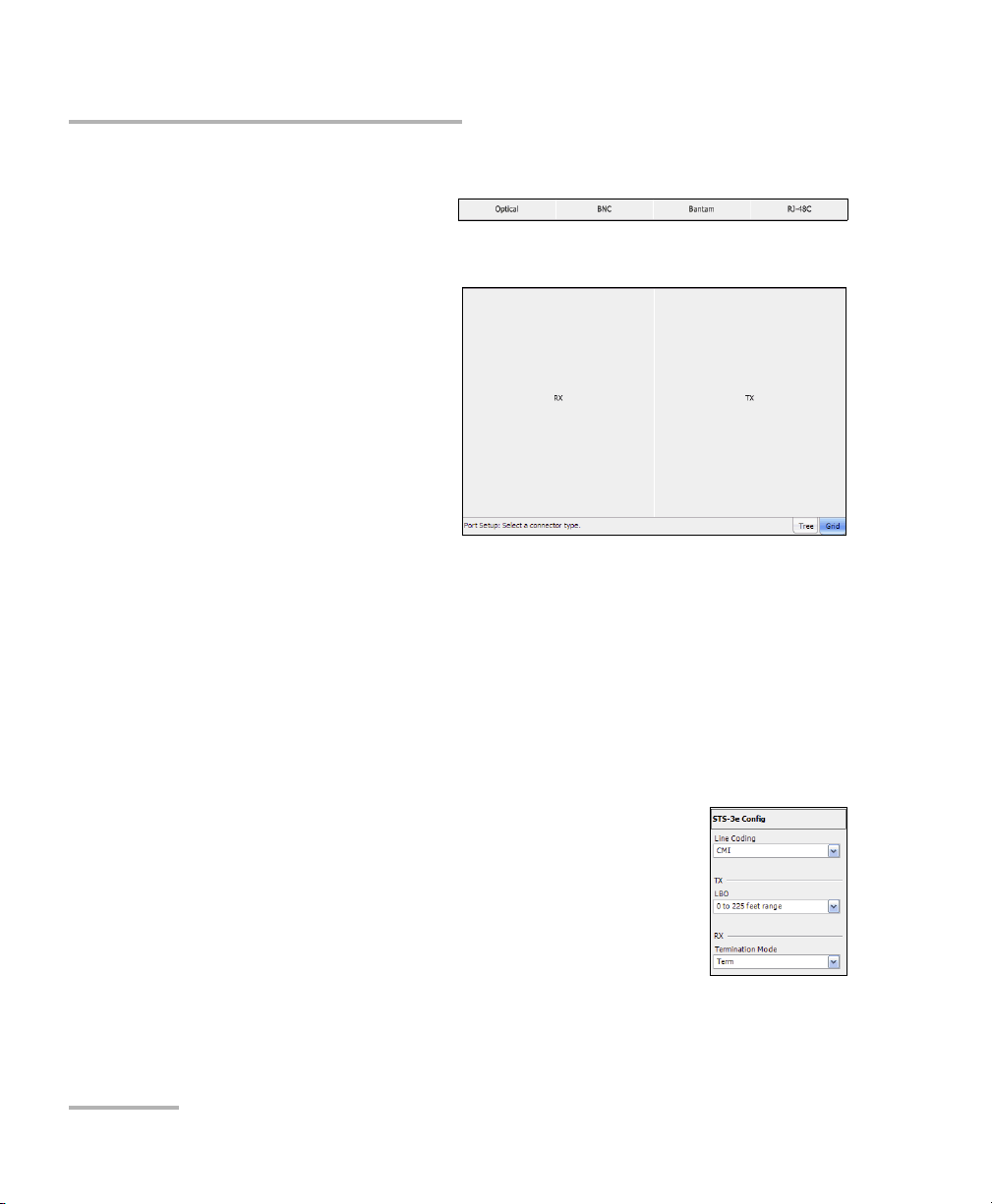
Creating and Starting a Test Case
Typic a l Tes t Cases
2. Interface connector selection:
2a. From the data path
selector, press the
BNC electrical interface connector.
2b. For Decoupled test
mode, both TX and
RX ports have to be
selected and
configured:
First select the
interface type for
TX from the data
path selector then
proceed with the
rest of the test setup steps to set the test parameters for the TX
interface. At the end, do not press Finish yet. Press Back to return
to the RX/TX selection screen and select the interface type for RX
from the data path selector then proceed with the rest of the test
setup steps to set the test parameters for the RX interface.
2c. Press Next.
3. Interface selection and configuration:
3a. Press the desired interface: STS-3e, STS-1e, STM-1e, or STM-0e.
3b. Select the Line Coding, TX LBO, and RX
Termination Mode (Ter m or Mon). For more
information, refer Port TX (Electrical Interfaces)
on page 138 for Line Coding and LBO, to RX DSn Tabs on page 269 or PDH Tabs on page 369
for Termination Mode.
3c. Press Next.
80 IQS-8100 Series Transport Blazer
Page 95

Creating and Starting a Test Case
4. Select the test
path/mapping.
4a. From the data path
selector, press the
desired
path/mapping.
Choices depend on
the selected
interface. See
Supported
Paths /M app ing s on
page 59 for more
information.
4b. Press a timeslot from the Grid tab when applicable.
4c. For STS/STM and VT/AU mapping level, select
the Enable TCM check box if needed.
4d. For DSn/ P D H m a pp in g le v e l,
select the Framing. For more
information, refer to DSn Tabs or
PDH Tabs.
Typical Tes t C a s e s
For DS3, sel e c t t h e Enable FEAC
check box to allow far end alarm and control testing.
For DS1, sel e c t t h e Enable FDL check box to allow facility data
link testing.
For DS1/E1, select the Enable DS0/E0 check box to allow DS0 or
E0 testing.
4e. For Pattern, go to step 5.
4f. Press Next or Finish.
4g. Repeat step 4 as required to complete the path/mapping. See
Supported Paths/Mappings on page 59 for more information.
SONET/SDH Application 81
Page 96
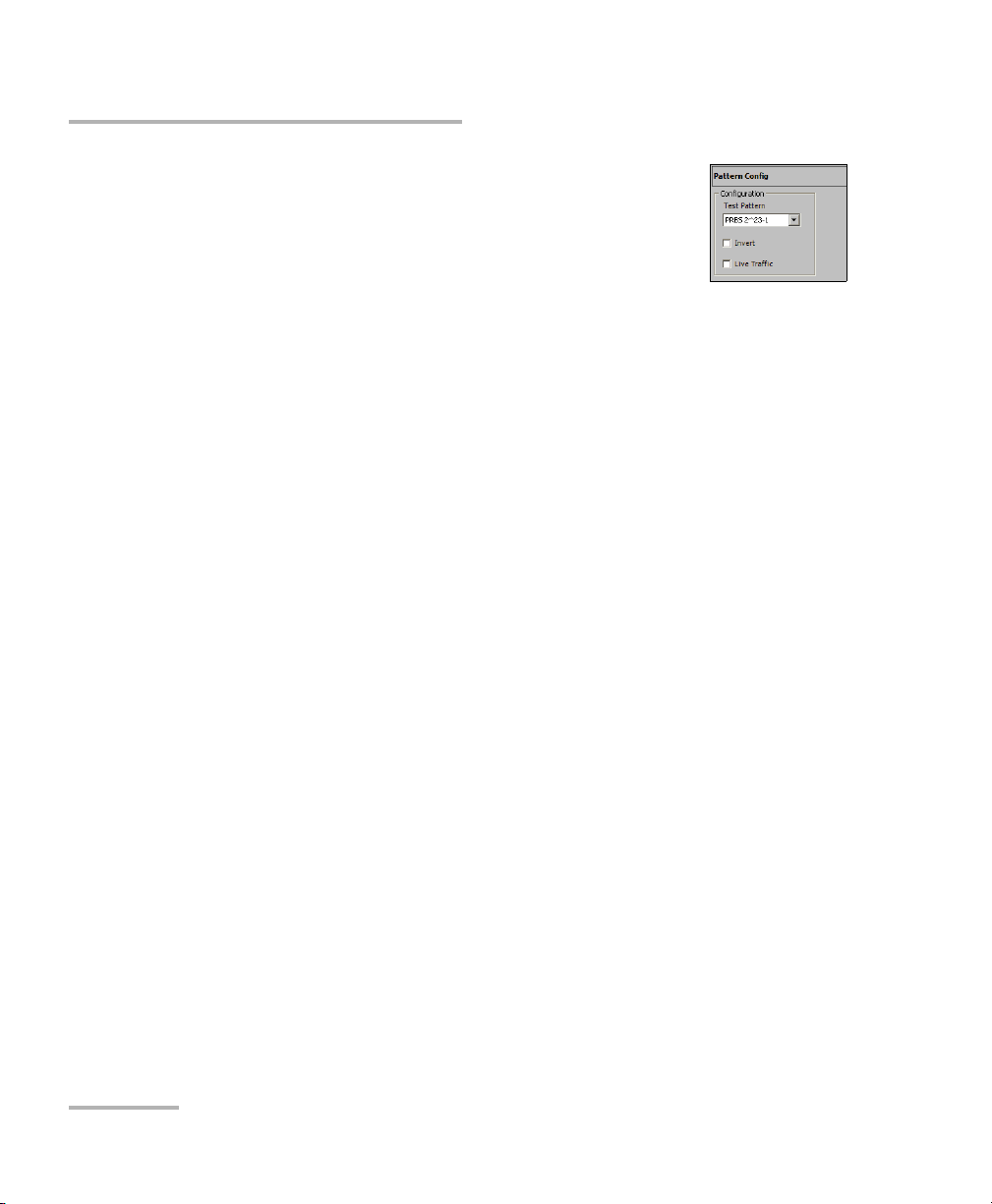
Creating and Starting a Test Case
Typic a l Tes t Cases
5. Pattern Configuration:
5a. Set the pattern parameters. Refer to Pattern TX
on page 405 and Patter n R X on page 409 for
more information.
6. Press Finish to complete the test setup. The Grid tab
closes and automatically switch to the Alarm summary tab.
7. For additional configuration parameters and results, refer to Summary
Tab s on page 125, Port Tabs on page 137, SONET Tabs on page 211,
DSn Tabs on page 269, SDH Tabs on page 303, PDH Tabs on page 369,
BERT Tabs on page 405, Advanced Tabs on page 411, and Common
Tab s on page 491.
8. Press the Start button to start the test. Refer to Global Test Status and
Controls on page 35 for more information on test management.
82 IQS-8100 Series Transport Blazer
Page 97

Creating and Starting a Test Case
Typical Tes t C a s e s
Creating an Optical SONET/SDH Test Case
(IQS-8115/20/30)
The following procedure describes a normal optical SONET/SDH the test
case on the IQS-8115/20/30 modules.
³ For Next generation test case, see Creating a Next Generation Test Case
including VCAT/LCAS and GFP on page 103.
³ For IQS-8140, see Creating an Optical SONET/SDH Test Case on an
IQS-8140 on page 87.
To create an Optical SONET/SDH Test on an IQS-8115/20/30 module:
1. Test configuration:
1a. Select the source Clock Mode that will be used
for the test. Refer to Clock Configuration on
page 129 for more information.
1b. Select Normal as the Te s t Mod e. Refer to Test
Configuration on page 126 for more information.
1c. Select the Coupled check box to set the same
settings for both the TX and RX signals or clear
the Coupled check box to configure the TX and RX signal
individually (decoupled).
1d. Select the Through check box to loop the RX signal to the TX port.
The Clock Mode is automatically set to Recovered when the
Through check box is selected.
1e. Select the SONET/SDH Intrusive check box to loop the RX signal
to the TX port with TX overwrite capabilities. SONET/SDH
Intrusive is not available on IQS-8115.
1f. Leave the OTN Intrusive check box cleared. OTN Intrusive is not
available on IQS-8115.
1g. Press Next.
SONET/SDH Application 83
Page 98
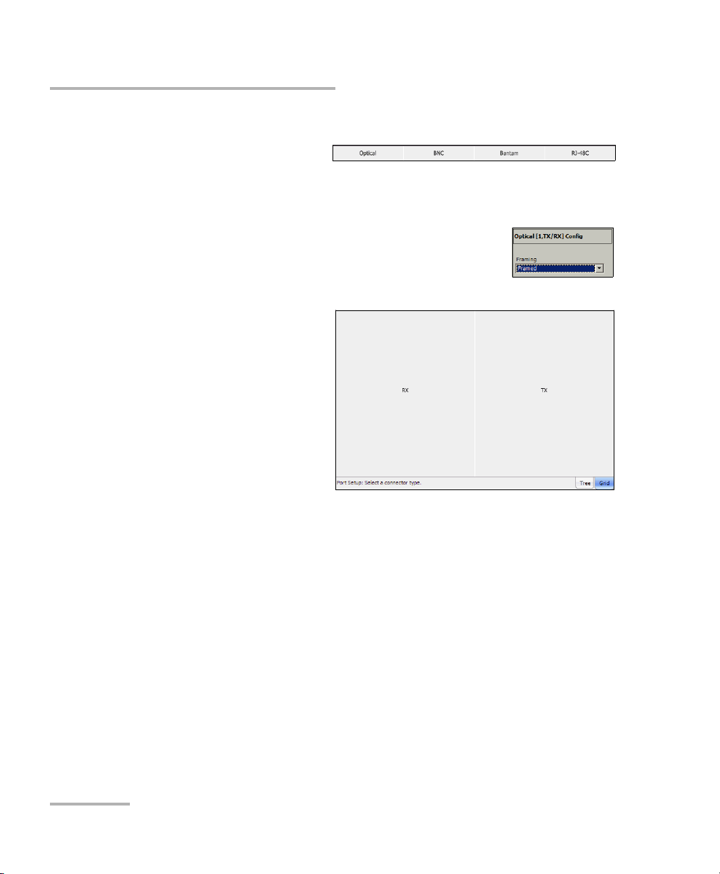
Creating and Starting a Test Case
Typic a l Tes t Cases
2. Interface connector selection:
2a. From the data path
selector, press the
Optical interface connector. Optical is automatically selected
when SONET/SDH Intrusive check box is selected.
2b. For OC-192/STM-64 select Framed or
Unframed. Framed is automatically selected in
Through or decoupled mode. For all other
optical interfaces, select Framed.
2c. For Decoupled test
mode, both TX and
RX ports have to be
selected and
configured:
First select the
interface type for
TX from the data
path selector then
proceed with the
rest of the test setup steps to set the test parameters for the TX
interface. At the end, do not press Finish yet. Press Back to return
to the RX/TX selection screen and select the interface type for RX
from the data path selector then proceed with the rest of the test
setup steps to set the test parameters for the RX interface.
2d. Press Next.
3. Interface selection:
3a. Press the desired interface: OC-3, OC-12, OC-48, OC-192, STM-1,
STM-4, STM-16, STM-64. Choices depend on the rates available
on the IQS-8115/20/30 module.
3b. Press Next. For OC-192/STM64 interface with Unframed mode, go
to step 5.
84 IQS-8100 Series Transport Blazer
Page 99
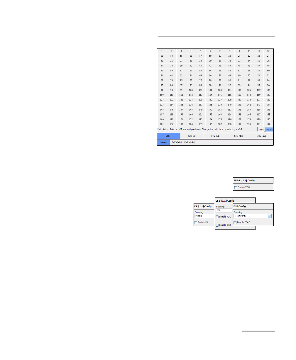
Creating and Starting a Test Case
4. Select the test
Path/Mapping.
4a. From the Data Path
Selector, select
Normal.
4b. From the data path
selector, press the
desired path/
mapping. Choices
depend on the
selected interface.
See Supported
Paths /M app ing s on
page 59 for more information.
4c. Press a timeslot from the Grid tab when applicable.
4d. For STS/STM and VT/AU mapping level, select
the Enable TCM check box if needed.
Typical Tes t C a s e s
4e. For D S n/ P DH m ap pi n g l e ve l ,
select the Framing. For more
information, refer to DSn Tabs or
PDH Tabs.
For DS3, sel e c t t h e Enable FEAC
check box to allow far end alarm and control testing.
For DS1, sel e c t t h e Enable FDL check box to allow facility data
link testing.
For DS1/E1, select the Enable DS0/E0 check box to allow DS0 or
E0 testing.
SONET/SDH Application 85
Page 100
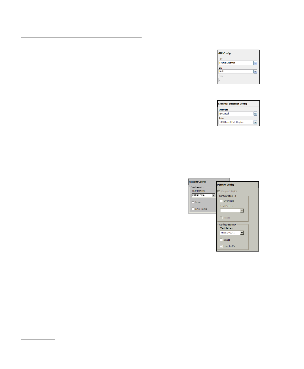
Creating and Starting a Test Case
Typic a l Tes t Cases
4f. For GFP, select the UPI (User Payload Identifier),
EXI (Extension Header Identifier), and CID
(Channel IDentifier) parameters. GFP is
available in Coupled test mode only. Refer to
GFP Frame TX on page 432 for UPI and EXI, and
to GFP Channel TX on page 435 for CID.
4g. For External Ethernet, which is available with
GFP, select the interface and its rate. Refer to
GFP Client TX on page 444 for more information.
Go to step 8.
4h. For Pattern, go to step 5.
4i. Press Next or Finish.
4j. Repeat step 4 as required to complete the path/mapping. See
Supported Paths/Mappings on page 59 for more information.
5. Pattern Configuration:
5a. Set the pattern parameters. Refer to
Patter n TX on page 405 and Pattern
RX on page 409 for more
information.
6. Press Finish to complete the test setup.
The Grid tab closes and automatically
switch to the Alarm summary tab.
7. For additional configuration parameters
and results, refer to Summary Tabs on page 125, Port Tabs on page 137,
SONET Tabs on page 211, DSn Tabs on page 269, SDH Tabs on
page 303, PDH Tabs on page 369, BERT Tabs on page 405, Advanced
Tab s on page 411, and Common Tabs on page 491. For Unframed
mode, only Summary, Port, and BERT tabs are available.
8. Press the Start button to start the test. Refer to Global Test Status and
Controls on page 35 for more information on test management.
86 IQS-8100 Series Transport Blazer
 Loading...