

Page 1
IQS-600
Integrated Qualification System
User Guide
Page 2

Copyright © 2008–2014 EXFO Inc. All rights reserved. No part of this
publication may be reproduced, stored in a retrieval system or transmitted
in any form, be it electronically, mechanically, or by any other means such
as photocopying, recording or otherwise, without the prior written
permission of EXFO Inc. (EXFO).
Information provided by EXFO is believed to be accurate and reliable.
However, no responsibility is assumed by EXFO for its use nor for any
infringements of patents or other rights of third parties that may result from
its use. No license is granted by implication or otherwise under any patent
rights of EXFO.
EXFO’s Commerce And Government Entities (CAGE) code under the North
Atlantic Treaty Organization (NATO) is 0L8C3.
The information contained in this publication is subject to change without
notice.
Trademarks
EXFO’s trademarks have been identified as such. However, the presence
or absence of such identification does not affect the legal status of any
trademark.
Units of Measurement
Units of measurement in this publication conform to SI standards and
practices.
Version number: 5.0.1
ii IQS-600
Page 3

Contents
Certification Information ......................................................................................................vii
1 Introducing the IQS-600 Integrated Qualification System ........................ 1
Main Features .........................................................................................................................1
Available Models ....................................................................................................................3
Understanding the LEDs .........................................................................................................8
Understanding the Hardware Buttons
and Selection Dial (IQS-605P-HS) ....................................................................................10
Locating Integrated Qualification System Synchronization Ports ..........................................11
Dual Hard Disk Drive .............................................................................................................12
Conventions ..........................................................................................................................13
2 Safety Information ..................................................................................... 15
Laser Safety Information .......................................................................................................15
Electrical Safety Information .................................................................................................16
Other Safety Symbols on Your Unit .......................................................................................19
3 Getting Started with Your Integrated Qualification System ................... 21
Installing Your Controller and Expansion Units in a Rackmount ............................................22
Connecting One or More Expansion Units to a Controller Unit .............................................26
Inserting and Removing Test Modules .................................................................................30
Safeguarding Units with the Interlock ..................................................................................36
Turning the Integrated Qualification System On and Off ......................................................38
Installing or Upgrading the Applications ..............................................................................39
Activating Software Options .................................................................................................42
Protecting your Unit with an Antivirus Software ...................................................................46
Accessing IQS Manager ........................................................................................................47
Exiting IQS Manager .............................................................................................................48
Installing EXFO LabVIEW Drivers ...........................................................................................49
Integrated Qualification System iii
Page 4

4 Setting Up Your Integrated Qualification System .....................................51
Calibrating Your Touchscreen (IQS-605P-HS) .........................................................................51
Installing an External Monitor ...............................................................................................52
Adjusting the Display and Sound ..........................................................................................54
Changing the Backlight Level (IQS-605P-HS) .........................................................................56
Deactivating the LED Display ................................................................................................56
Selecting the Language of Operation ...................................................................................57
Setting Date and Time Formats .............................................................................................67
Adjusting the Date, Time and Time Zone ..............................................................................69
Installing an External Keyboard .............................................................................................70
Activating the On-Screen Keyboard ......................................................................................71
Installing a Mouse ................................................................................................................73
Installing a Tape, CD, or DVD Player ......................................................................................74
Installing a Headset or a Speaker ..........................................................................................75
Installing a Microphone ........................................................................................................76
Installing a Printer ................................................................................................................77
Selecting the Startup Interface .............................................................................................78
Customizing Access Levels ....................................................................................................79
Setting Up Auto Logon for Windows ....................................................................................81
Setting Communication Parameters .....................................................................................84
Adjusting the Fan Speed .......................................................................................................84
Saving and Opening Configurations .....................................................................................86
Saving the Configuration on Exiting .....................................................................................88
Changing Unit and Module Identification ............................................................................89
Reverting to Factory Settings ................................................................................................91
5 Using the IQS Manager Interface ...............................................................93
Accessing Current Modules ..................................................................................................93
Accessing Integrated Applications ........................................................................................96
Working on Test Results (Offline Mode) ................................................................................97
Creating an Integrated Data Display .....................................................................................98
Viewing PDF Files ................................................................................................................100
Locating Units .....................................................................................................................102
Accessing Utilities from IQS Manager .................................................................................103
Accessing Utilities from Windows .......................................................................................103
6 Accessing your IQS-600 Remotely ............................................................105
Working with Remote Desktop ...........................................................................................106
Allowing User with Limited Accounts to Use Remote Desktop ...........................................108
Working with TightVNC ......................................................................................................114
iv IQS-600
Page 5

7 Preparing for Automation ....................................................................... 121
Configuring Your Integrated Qualification System for Working with GPIB ..........................125
Preparing Hardware for GPIB Control .................................................................................132
Linking Units with the GPIB Port .........................................................................................134
Linking Units with the Ethernet Port ...................................................................................134
Linking Units with the Serial Port ........................................................................................135
Getting Optimum Performance from Your Integrated Qualification System .......................135
Changing Communication Settings ....................................................................................138
Configuring DCOM Access to Your Unit ..............................................................................143
Preparing to Control Modules with a Dedicated Application ..............................................167
8 Using IQS Products in an Automated Test Environment ........................ 171
Managing the States of Your IQS-600 Integrated Qualification System ..............................172
Message Management .......................................................................................................176
Standard Status Data Structure ..........................................................................................179
SCPI Command Structure ....................................................................................................183
Consulting Data Types ........................................................................................................188
Writing Remote Control Code .............................................................................................188
Error Message Format .........................................................................................................190
Working with EXFO COM Objects .......................................................................................191
Working with EXFO LabVIEW Drivers ..................................................................................192
Using the EXFO Getting Started Applications .....................................................................194
Building and Using Custom VIs ...........................................................................................199
Monitoring Remote Commands ..........................................................................................205
9 Maintenance ............................................................................................. 209
Cleaning the Touchscreen (IQS-605P-HS) ............................................................................209
Replacing the Fuse ..............................................................................................................210
Managing Windows Updates .............................................................................................210
Recycling and Disposal (Applies to European Union Only) ..................................................212
10 Troubleshooting ....................................................................................... 213
Solving Common Problems .................................................................................................213
Restoring Your Controller Unit to Normal Operation .........................................................216
Viewing Online Documentation ..........................................................................................234
Contacting the Technical Support Group ............................................................................235
Viewing System Information ...............................................................................................236
Transportation ....................................................................................................................240
Integrated Qualification System v
Page 6

11 Warranty ....................................................................................................241
General Information ...........................................................................................................241
Liability ...............................................................................................................................241
Exclusions ...........................................................................................................................242
Certification ........................................................................................................................242
Service and Repairs .............................................................................................................243
EXFO Service Centers Worldwide ........................................................................................244
A Technical Specifications ............................................................................245
B SCPI-Based Errors ......................................................................................247
C Data Types .................................................................................................263
Applicable Data Types for Input—IEEE 488.2 ......................................................................264
Applicable Data Types for Output —IEEE 488.2 ..................................................................273
Applicable Data Types for Input—SCPI ................................................................................283
Special Numeric Values Received on Output .......................................................................284
D IEEE 488.2 and Specific Commands .........................................................285
IEEE 488.2 Commands–Quick Reference .............................................................................285
IEEE 488.2 Required Commands .........................................................................................286
Specific Commands—Quick Reference ................................................................................306
Specific Commands ............................................................................................................307
E COM Properties and Events ......................................................................325
ActiveX (COM/DCOM)—Quick Reference ............................................................................326
Properties ...........................................................................................................................327
Events .................................................................................................................................334
F Using the IQS-9600 Utility Module ...........................................................335
Index ...............................................................................................................339
vi IQS-600
Page 7

Certification Information
Certification Information
North America Regulatory Statement
This unit was certified by an agency approved in both Canada and the
United States of America. It has been evaluated according to applicable
North American approved standards for product safety for use in Canada
and the United States.
Electronic test and measurement equipment is exempt from FCC part 15,
subpart B compliance in the United States of America and from ICES-003
compliance in Canada. However, EXFO Inc. makes reasonable efforts to
ensure compliance to the applicable standards.
The limits set by these standards are designed to provide reasonable
protection against harmful interference when the equipment is operated in
a commercial environment. This equipment generates, uses, and can
radiate radio frequency energy and, if not installed and used in accordance
with the user guide, may cause harmful interference to radio
communications. Operation of this equipment in a residential area is likely
to cause harmful interference in which case the user will be required to
correct the interference at his own expense.
Modifications not expressly approved by the manufacturer could void the
user's authority to operate the equipment.
IMPORTANT
Use of shielded remote I/O cables, with properly grounded shields
and metal connectors, is recommended in order to reduce radio
frequency interference that may emanate from these cables.
Integrated Qualification System vii
Page 8

Certification Information
European Community Declaration of Conformity
An electronic version of the declaration of conformity for your product is
available on our website at www.exfo.com. Refer to the product’s page on
the Web site for details.
viii IQS-600
Page 9

1 Introducing the IQS-600
Integrated Qualification
System
Main Features
The IQS-600 Integrated Qualification System is a platform designed for
scientific and industrial applications. It is composed of one IQS-605P-HS or
IQS-610P-HS controller unit and up to nine optional IQS-610E-HS expansion
units.
IMPORTANT
The high-speed units bear the “HS” inscription on their front
panels, while the standard IQS-600 units do not.
You can link both high-speed and standard units that you may
already have. However, to benefit from the high-speed feature,
you must chain the units in a specific order: all the high-speed
units first, followed by all the standard units.
When several high-speed units are linked, the high-speed
capability is available for the first three high-speed units only.
High-speed modules only work with high-speed units. For this
reason, ensure that you insert such modules into one of the first
three high-speed units. Otherwise, you will not be able to work
with the modules.
There is no risk of damaging your high-speed modules by
inserting them into a standard unit.
High-speed modules are identified as such in their user
documentation.
Most of the standard modules will work either in high-speed or
standard units.
Use only accessories designed for your unit and approved by
EXFO. For a complete list of accessories available for your unit,
see the technical specification sheet.
Integrated Qualification System 1
Page 10

Introducing the IQS-600 Integrated Qualification System
Main Features
Both controller and expansion units are designed to work with IQS
modules, including the utility module (for which you will find more
information in Using the IQS-9600 Utility Module on page 335). The
controller and expansion units also allow you to work with most IQ
modules if you have previously purchased any. For a complete list of
supported modules, go to the EXFO Web site.
The IQS-600 Integrated Qualification System runs under Microsoft
Windows 8.1 Pro with the IQS Manager software. Your controller unit
features several possibilities, such as trigger and remote control ports,
interlock terminals, as well as standard computer ports.
The IQS-600 Integrated Qualification System supports local control (via the
IQS Manager software) and remote control (through GPIB, RS-232 or
Ethernet TCP/IP—using SCPI commands or the provided LabVIEW
drivers).
2 IQS-600
Page 11
Introducing the IQS-600 Integrated Qualification System
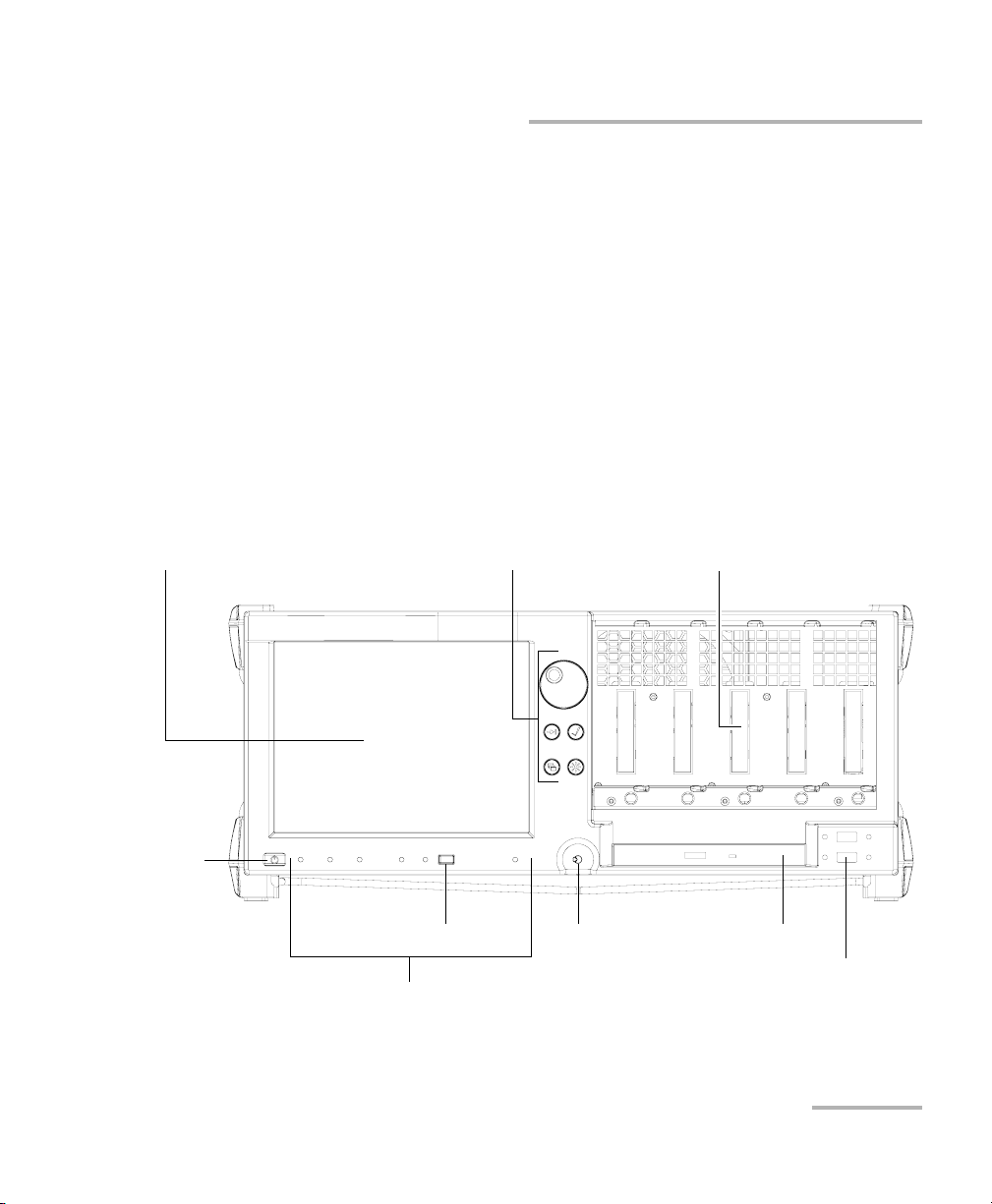
Module connector pins
On/Off
button
USB 2.0 ports (2)
Stylus
Hardware buttons and selection dial (see
Understanding the Hardware Buttons and
Selection Dial (IQS-605P-HS) on page 10)
DVD-RW drive
LED indicators (see Understanding the
LEDs on page 8)
Touchscreen
Return to Local button
Available Models
Available Models
Below are diagrams to locate the components on your controller and
expansion units.
IQS-605P-HS Controller Unit
The front of the IQS-605P-HS controller unit is where you perform basic
operations such as turning your unit on or off, consulting LED indicators,
and using data-related peripherals (for example: the USB ports).
Note: Some features, such as the touchscreen and selection dial, may not be
available depending on the version of the software you are using.
Integrated Qualification System 3
Page 12
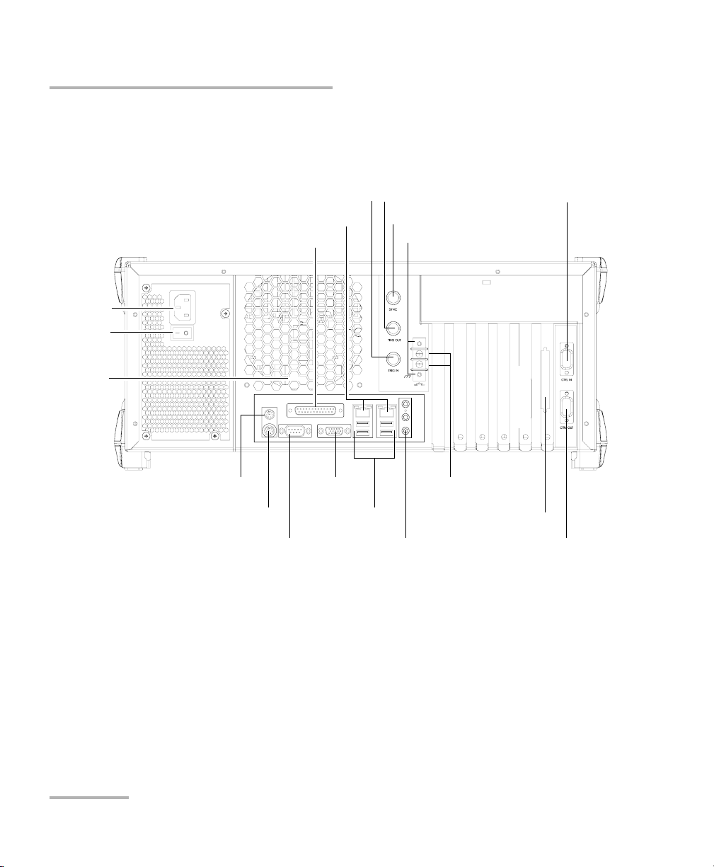
Introducing the IQS-600 Integrated Qualification System
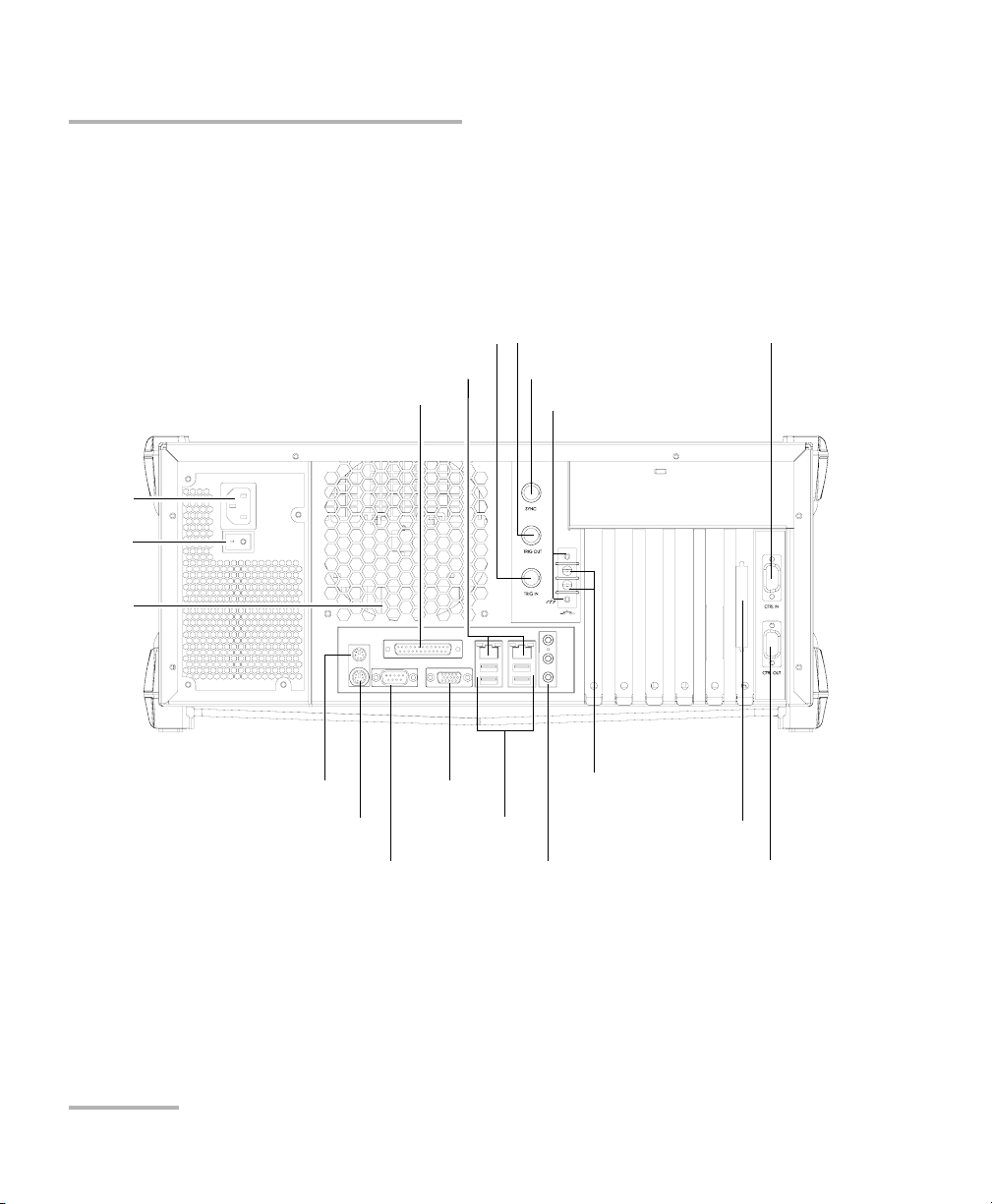
Control Out port
Interlock ground terminals (2)
Audio ports (3)
USB ports (4)
Serial port
Ethernet port (2)
Parallel (printer) port
AC
socket
Main
power
switch
Trigger input
BNC synchronization port
EXFO Bus Out port
Control In port
PS/2 keyboard port
PS/2 mouse port
Interlock ground
terminals (2)
Trigger output
Monitor port
Fan
Available Models
The back of the IQS-605P-HS controller unit is where you find the
peripheral connectors, as well as the power outlets and connectors to link
expansion units to your controller unit.
4 IQS-600
Page 13
Introducing the IQS-600 Integrated Qualification System
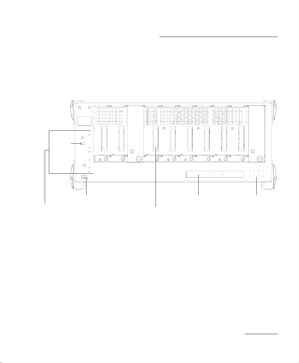
DVD-RW drive
Module connector pins
On/Off button
USB 2.0 ports (2)
LED indicators (see
Understanding the LEDs on
page 8)
Return
to local
button
Available Models
IQS-610P-HS Controller Unit
The front of the IQS-610P-HS controller unit is where you perform basic
operations such as turning your unit on or off, consulting LED indicators
and using data-related peripherals (for example: the USB ports and the
DVD-RW drive).
Integrated Qualification System 5
Page 14
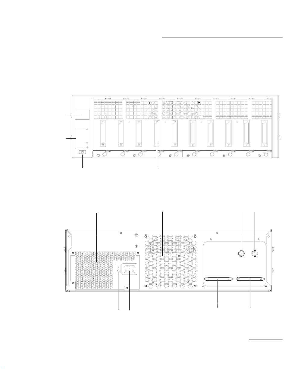
Introducing the IQS-600 Integrated Qualification System
Parallel (printer) port
PS/2 keyboard port
BNC synchronization port
Trigger output
Trigger input
Ethernet ports (2)
Serial port
Audio ports (3)
Interlock ground terminals (2)
Main
power
switch
AC socket
Monitor port
EXFO Bus Out port
Control Out port
Interlock ground
terminals (2)
PS/2 mouse port
USB ports (4)
Control In port
Fan
Available Models
The back of the IQS-610P-HS controller unit is where you find the
peripheral connectors, as well as the power outlets and connectors to link
expansion units to your controller unit.
6 IQS-600
Page 15
Introducing the IQS-600 Integrated Qualification System
On/Off button
Module connector pins
Position
display
LED
indicators
Fan
Trigger input
IQS-610E-HS
Bus In port
Trigger output
Power supply fan
Main power switch
AC socket
IQS-610P-HS
Bus Out port
Available Models
IQS-610E-HS Expansion Unit
The front of the IQS-610E-HS expansion unit is where you perform basic
operations such as turning your unit on or off and consulting LED
indicators.
The back of the IQS-610E-HS expansion unit is where you find the power
outlets and connectors to link your expansion units to your controller unit.
Integrated Qualification System 7
Page 16
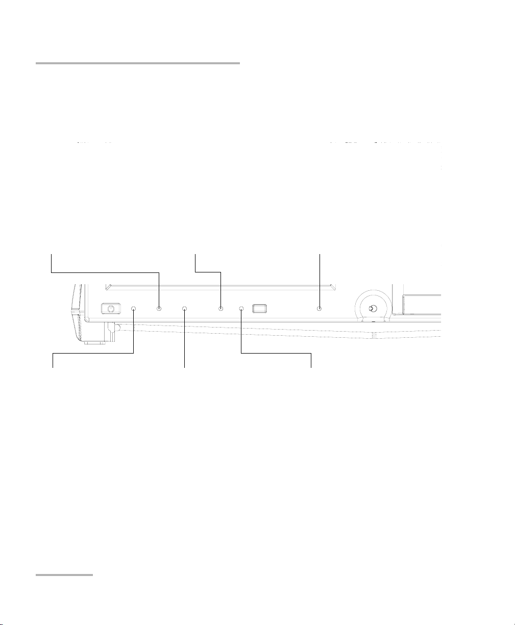
Introducing the IQS-600 Integrated Qualification System
Alarm indicator LED
When lit on the controller unit, it
indicates a problem.
When lit on an expansion unit, the
latter is not linked to the
controller directly or through a
chain.
Lock LED
When lit, the unit is in
Lockout mode; you can
only disable this mode by
sending the
corresponding remote
command.
Interlock LED
When lit, it indicates that
the Interlock is open (no
current is passing
through) and that the
lasers in your unit are
deactivated.
On/Off LED
When lit, it indicates that
the unit is currently on.
Hard drive activity LED
When blinking, it indicates
current hard drive activity.
Remote LED
When lit, the unit is in Remote
mode and the local peripherals
such as the keyboard, selection
dial and mouse are disabled.
IQS-605P-HS
Understanding the LEDs
Understanding the LEDs
The LEDs on your Integrated Qualification System help you determine the
current status of your unit.
8 IQS-600
Page 17
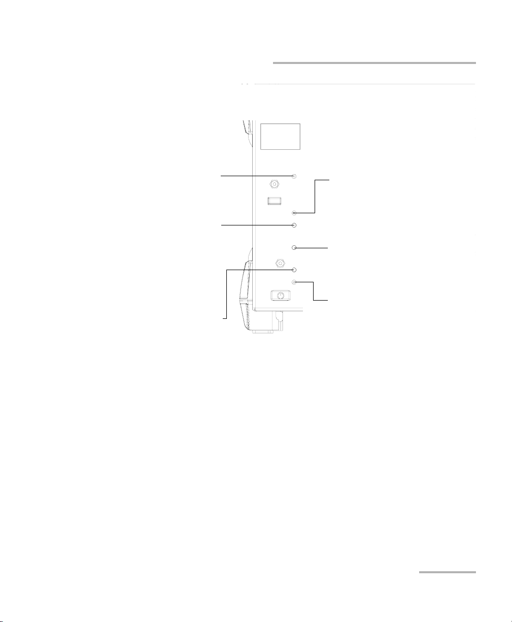
Introducing the IQS-600 Integrated Qualification System
Interlock LED
When lit, it indicates that the Interlock
is open (no current is passing through)
and that the lasers present in your unit
are deactivated.
Lock LED
When lit, the unit is in Lockout mode;
you can only disable this mode by
sending the corresponding remote
command.
Alarm indicator LED
When lit on the controller unit, it
indicates a problem.
When lit on an expansion unit, the
latter is not linked to the controller
directly or through a chain.
Remote LED
When lit, the unit is in Remote mode
and the keyboard and mouse are
disabled.
Hard drive activity LED
When blinking, it indicates current
hard drive activity.
On/Off LED
When lit, it indicates that the unit is
currently on.
IQS-610P-HS
Understanding the LEDs
Integrated Qualification System 9
Page 18

Introducing the IQS-600 Integrated Qualification System
Tab
This button allows you to switch between
fields on an interface, or between the
applications brought by the Program
Switcher button. It is the equivalent of
pressing the Tab key on a keyboard.
Enter
This button allows you to select the
highlighted element on the screen. It is
the equivalent of using the Enter key on
a keyboard.
Backlight
This button allows you to set the display
brightness level.
Program Switcher
This button allows you to access a list of
currently running applications. It is the
equivalent of pressing the Alt-Tab
combination on a keyboard.
Selection Dial
Turn it to scroll up or down in lists, or to move slider.
Push it to select the item you have highlighted in the list.
Understanding the Hardware Buttons and Selection Dial (IQS-605P-HS)
Understanding the Hardware Buttons
and Selection Dial (IQS-605P-HS)
The hardware buttons and selection dial on your Integrated Qualification
System allow you to perform various tasks.
Note: Some features, such as the touchscreen and selection dial, may not be
available depending on the version of the software you are using.
10 IQS-600
Page 19
Introducing the IQS-600 Integrated Qualification System
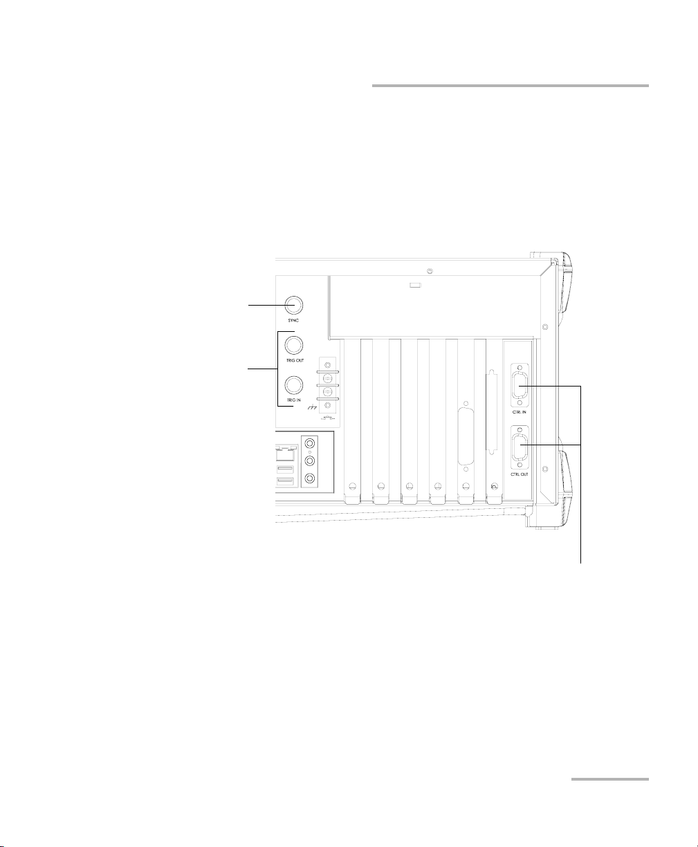
Control In/Out ports
Used to connect specific EXFO units together.
Reserved for EXFO.
Trigger input/output
BNC synchronization port
Locating Integrated Qualification System Synchronization Ports
Locating Integrated Qualification System
Synchronization Ports
The synchronization and trigger ports are not currently supported by the
IQS-600 Integrated Qualification System. The ports located at the back of
the unit are reserved for future use only.
Integrated Qualification System 11
Page 20

Introducing the IQS-600 Integrated Qualification System
Dual Hard Disk Drive
Dual Hard Disk Drive
The optional RAID 1 dual hard disk drive performs real-time mirroring of all
data. A safety against hard drive failure, the RAID 1 hard disk drive
configuration provides a live backup of all test data.
RAID 1 dual hard disk drives are installed at the factory. They cannot be
installed in the field. To retrofit your IQS-600 with this option, return your
unit to EXFO.
Windows will notify you of any malfunction with your RAID 1 hard drive.
Should this happen, your data is no longer protected from a single hard
drive failure. Contact EXFO’s Technical Support.
12 IQS-600
Page 21
Introducing the IQS-600 Integrated Qualification System
Conventions
Before using the product described in this guide, you should understand
the following conventions:
WARNING
Indicates a potentially hazardous situation which, if not avoided,
could result in death or serious injury. Do not proceed unless you
understand and meet the required conditions.
CAUTION
Indicates a potentially hazardous situation which, if not avoided,
may result in minor or moderate injury. Do not proceed unless you
understand and meet the required conditions.
CAUTION
Indicates a potentially hazardous situation which, if not avoided,
may result in component damage. Do not proceed unless you
understand and meet the required conditions.
Conventions
IMPORTANT
Refers to information about this product you should not overlook.
Integrated Qualification System 13
Page 22

Page 23
2 Safety Information
WARNING
Do not install or terminate fibers while a light source is active.
Never look directly into a live fiber and ensure that your eyes are
protected at all times.
WARNING
The use of controls, adjustments and procedures, namely for
operation and maintenance, other than those specified herein may
result in hazardous radiation exposure or impair the protection
provided by this unit.
IMPORTANT
When you see the following symbol on your unit , make sure
that you refer to the instructions provided in your user
documentation. Ensure that you understand and meet the required
conditions before using your product.
IMPORTANT
Other safety instructions relevant for your product are located
throughout this documentation, depending on the action to
perform. Make sure to read them carefully when they apply to your
situation.
Laser Safety Information
Your IQS-600 Integrated Qualification System does not include laser
components in itself. However, your modules may do so. Refer to your
modules’ user guides for information on their respective laser classes, and
further laser safety details and instructions.
Integrated Qualification System 15
Page 24

Safety Information
Electrical Safety Information
Electrical Safety Information
This unit uses an international safety standard three-wire power cable. This
cable serves as a ground when connected to an appropriate AC power
outlet.
Note: If you need to ensure that the unit is completely turned off, disconnect the
power cable.
WARNING
Insert the power cable plug into a power outlet with a
protective ground contact. Do not use an extension cord
without a protective conductor.
Before turning on the unit, connect all grounding terminals and
extension cords to a protective ground via a ground socket. Any
interruption of the protective grounding is a potential shock
hazard and may cause personal injury. Whenever the ground
protection is impaired, do not use the unit and secure it against
any accidental operation.
Do not tamper with the protective ground terminal.
Use only the certified power cord that is suitably rated for the
country where the unit is sold.
Replacing detachable MAINS supply cords by inadequately
RATED cords may result of overheating of the cord and create a
risk of fire.
16 IQS-600
Page 25

Safety Information
Electrical Safety Information
The color coding used in the electric cable depends on the cable. New
plugs should meet the local safety requirements and include:
adequate load-carrying capacity
ground connection
cable clamp
WARNING
Use this unit indoors only.
Position the unit so that the air can circulate freely around it.
Do not remove unit covers during operation.
Operation of any electrical instrument around flammable gases
or fumes constitutes a major safety hazard.
To avoid electrical shock, do not operate the unit if any part of
the outer surface (covers, panels, etc.) is damaged.
Only authorized personnel should carry out adjustments,
maintenance or repair of opened units under voltage. A person
qualified in first aid must also be present. Do not replace any
components while the power cable is connected.
Capacitors inside the unit may be charged even if the unit has
been disconnected from its electrical supply.
Integrated Qualification System 17
Page 26
Safety Information
Electrical Safety Information
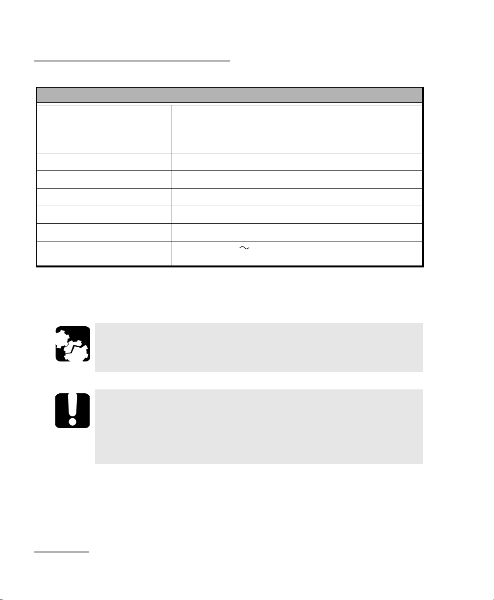
Equipment Ratings
Tem pe rat ur e
Operation
Storage
Relative humidity
Maximum operation altitude 2000 m (6562 ft)
Pollution degree 2
Overvoltage category II
Measurement category Not rated for measurement categories II, III, or IV
Input power
a. Measured in 0 °C to 31 °C (32 °F to 87.8 °F) range, decreasing linearly to 50 % at 40 °C (104 °F).
b. Not exceeding ± 10 % of the nominal voltage.
a
b
0 °C to 40 °C (32 °F to 104 °F)
–40 °C to 70 °C (–40 °F to 158 °F)
0 % to 80 % non-condensing
unit: 100 - 240 V; 50/60 Hz; 550 VA
CAUTION
The use of voltages higher than those indicated on the label affixed
to your unit may damage the unit.
IMPORTANT
The operation and storage temperatures of some modules may
differ from the temperatures specified for your platform. In this
case, always ensure that you comply with the most restrictive
conditions (either module or platform).
18 IQS-600
Page 27
Safety Information
Other Safety Symbols on Your Unit
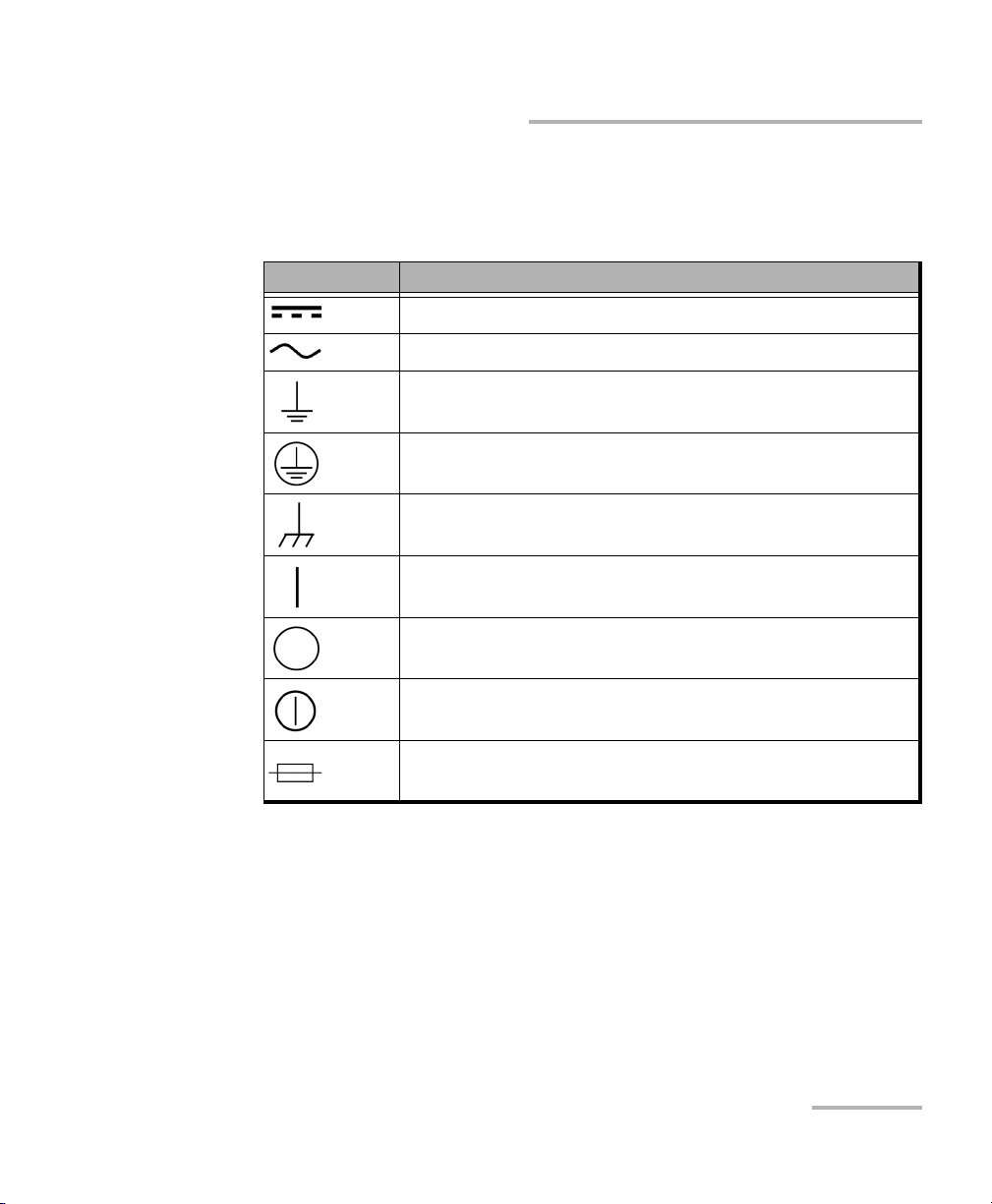
Other Safety Symbols on Your Unit
One or more of the following symbols may also appear on your unit.
Symbol Meaning
Direct current
Alternating current
The unit is equipped with an earth (ground) terminal.
The unit is equipped with a protective conductor terminal.
The unit is equipped with a frame or chassis terminal.
On (Power)
Off (Power)
On/Off (Power)
Fuse
Integrated Qualification System 19
Page 28

Page 29
3 Getting Started with Your
No
Yes
Integrated Qualification
System
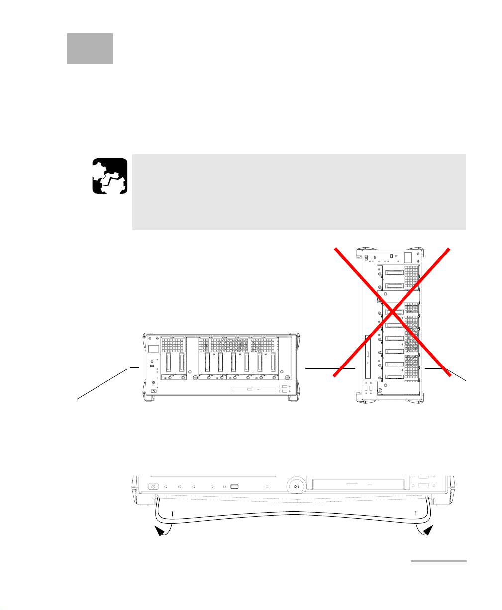
You can either use your IQS-600 Integrated Qualification System as a
benchtop unit, or you can install your units in a rackmount.
CAUTION
If you are using your Integrated Qualification System as a benchtop
unit, do not turn it on its side. The platforms and modules were not
designed to function in this position and, therefore, would either
be damaged or provide inaccurate measurements.
You can adjust the angle of your IQS-605P-HS controller unit in order to
have a better view of the screen. Use the stand located under the front part
of the unit and pull it down and forward.
Integrated Qualification System 21
Page 30

Getting Started with Your Integrated Qualification System
Installing Your Controller and Expansion Units in a Rackmount
Installing Your Controller and Expansion Units
in a Rackmount
Your controller and expansion units were designed to be installed in
19-inch rackmounts only. They will not fit into 23-inch racks.
Each unit has a side fan and a rear cooling fan. Mount or position your units
so that air can circulate freely around them. When operating the units,
select a location that provides at least:
75 mm (3 in.) of rear clearance
25 mm (1 in.) of side clearance (left and right)
CAUTION
Failure to provide adequate cooling clearance may result in an
excessive internal temperature, thus reducing the reliability of your
units.
Note: There is no need to leave an empty slot between units when you stack
them one on top of the other inside a rackmount.
Install your controller and expansion units into a rackmount kit before
inserting them into a rack.
IMPORTANT
High-speed units bear the “HS” inscription on their front panels,
while the standard units do not.
You can link both high-speed and standard units. However, to
benefit from the high-speed feature, you must chain the units
in a specific order: all the high-speed units first, followed by all
the standard units.
22 IQS-600
Page 31

Getting Started with Your Integrated Qualification System
Installing Your Controller and Expansion Units in a Rackmount
To prepare your unit for rackmount use:
1. Ensure that your unit is turned off.
2. Remove the bumpers of your controller unit by unscrewing the top and
bottom screws.
CAUTION
You should remove all your modules before installing your unit into
a rackmount. Otherwise, they could be damaged or their calibration
could be affected.
Integrated Qualification System 23
Page 32

Getting Started with Your Integrated Qualification System
Rackmount screws
IQS-600 unit
Handle
Rackmount screws
Installing Your Controller and Expansion Units in a Rackmount
3. Assemble the rackmount kit panels using the supplied screws.
The screws used for the bumpers will not work to secure the
rackmount kit panels. You must use the screws supplied with the kit.
24 IQS-600
Page 33

Getting Started with Your Integrated Qualification System
Installing Your Controller and Expansion Units in a Rackmount
4. Insert the rackmounted unit into the cabinet as shown below and
secure it in place using the hardware supplied with the rack.
5. Repeat steps 1 through 3 for each unit being installed in the rackmount.
If you want to move a unit forward or backward in the rackmount,
untighten the screws on each side of the rackmount kit slightly and slide
the unit forward or backward. Retighten the screws afterwards.
Integrated Qualification System 25
Page 34

Getting Started with Your Integrated Qualification System
Connecting One or More Expansion Units to a Controller Unit
Connecting One or More Expansion Units to a
Controller Unit
It is possible to connect expansion units to your controller unit. You can
either stack your units on a desk or install them in a rackmount
(see Installing Your Controller and Expansion Units in a Rackmount on
page 22 for instructions).
Note: As your expansion units are daisy chained, the position is indicated by a
number displayed on the unit’s position display.
IMPORTANT
High-speed units bear the “HS” inscription on their front panels,
while the standard units do not.
You can link both high-speed and standard units. However, to
benefit from the high-speed feature, you must chain the units
in a specific order: all the high-speed units first, followed by all
the standard units.
26 IQS-600
Page 35

Getting Started with Your Integrated Qualification System
EXFO controller Bus Out port
Connecting One or More Expansion Units to a Controller Unit
To connect an Expansion Unit to a Controller Unit:
1. Connect the provided cable to the EXFO Bus Out port located at the
back of your controller unit.
IMPORTANT
To ensure that your cable is properly connected, firmly push the IQS
interface cable into the port until it clicks twice. An improper
connection might cause operation problems.
Integrated Qualification System 27
Page 36

Getting Started with Your Integrated Qualification System
EXFO expansion unit Bus In port
EXFO expansion unit Bus Out port
Connecting One or More Expansion Units to a Controller Unit
2. Connect the other end of the cable to the EXFO Bus In port located at
the back of your expansion unit.
28 IQS-600
Page 37

Getting Started with Your Integrated Qualification System
Connecting One or More Expansion Units to a Controller Unit
3. To connect additional IQS-610E-HS expansion units to your system, use
another cable to connect the EXFO Bus Out port of the first unit to the
EXFO Bus In port of the second unit.
4. Repeat the previous steps for each additional unit you want to connect.
Integrated Qualification System 29
Page 38

Getting Started with Your Integrated Qualification System
Inserting and Removing Test Modules
Inserting and Removing Test Modules
CAUTION
Never insert or remove a module while the controller unit and its
expansion units are turned on. This will result in immediate and
irreparable damage to both the module and unit.
CAUTION
To avoid damaging your unit, use it only with modules approved by
EXFO.
30 IQS-600
Page 39

Getting Started with Your Integrated Qualification System
Retaining screw
knob
Protective cover
2b
2a
Inserting and Removing Test Modules
To insert a module into the controller or expansion unit:
1. Exit IQS Manager and turn off all your units.
2. Remove the protective cover from the desired unused module slot.
2a. Pull the retaining screw knob firmly towards you and release the
bottom of the cover.
2b. Gently pull the top of the protective cover downwards, to remove
it from the unit grooves.
3. Position the module so that its front panel is facing you and the top and
bottom protruding edges are to your right.
Integrated Qualification System 31
Page 40

Getting Started with Your Integrated Qualification System
Retaining screw
Retaining screw knob
Protruding edges
(right side of module)
5
6
Inserting and Removing Test Modules
4. Insert the protruding edges of the module into the grooves of the unit’s
module slot.
5. Push the module all the way to the back of the slot, until the retaining
screw makes contact with the unit casing.
6. While applying slight pressure to the module, turn the retaining screw
knob (located at the bottom of the panel) clockwise until the knob is
horizontal.
This will secure the module into its “seated” position.
32 IQS-600
Page 41

Getting Started with Your Integrated Qualification System
Retaining screw knob
Inserting and Removing Test Modules
The module is correctly inserted when its front panel is flush with the front
panel of the controller or expansion unit.
When you turn on the controller unit, the startup sequence will
automatically detect your module.
Note: You can insert IQ modules into your controller or expansion unit; the
IQS Manager software will recognize them. However, the IQS-600 locking
mechanism (retaining screw) will not work for IQ modules.
To remove a module from your controller or expansion unit:
1. While pulling gently on the knob, turn it counterclockwise until it stops.
The module will slowly be released from the slot.
2. Place your fingers underneath the module or hold it by the retaining
screw knob (NOT by the connector) and pull it out.
Integrated Qualification System 33
Page 42

Getting Started with Your Integrated Qualification System
YES
NO
Retaining screw
knob
Connector
Inserting and Removing Test Modules
CAUTION
Pulling out a module by a connector could seriously damage both
the module and connector. Always pull out a module by the
retaining screw knob.
3. Cover empty slots with the supplied protective covers.
3a. Slide the top of the protective cover into the upper grooves of the
unit.
3b. Snap the cover into place by pushing the retaining screw knob.
CAUTION
Failure to reinstall protective covers over empty slots will result in
ventilation problems.
34 IQS-600
Page 43

Getting Started with Your Integrated Qualification System
Bumper
Inserting and Removing Test Modules
Since IQ modules do not have retaining screw knobs to help you remove
them, EXFO provided you with a special tool to facilitate the operation.
To remove IQ modules:
1. Slide the tool’s end between the module front panel and the unit.
2. Using the bumper as the pivot point, push down the tool to release the
module.
3. Pull the module out.
Use the same precautions regarding module protective covers as you
would for your IQS modules.
Integrated Qualification System 35
Page 44

Getting Started with Your Integrated Qualification System
Door
Ground terminals Interlock terminals
Safeguarding Units with the Interlock
Safeguarding Units with the Interlock
EXFO’s more powerful and potentially harmful modules, such as laser
sources, are equipped with an interlock system that prevents accidental
power ups.
If your module is equipped with an interlock system, you might have to link
the terminals, located at the back of your IQS-610P-HS controller unit, with
the provided connectors.
You can connect your interlock terminals to an external safety device using
either your own connectors or the connectors provided by EXFO.
Note: If you are using shielded cables to connect your interlock terminals, use
either ground terminal to secure your connection.
36 IQS-600
Page 45

Getting Started with Your Integrated Qualification System
Safeguarding Units with the Interlock
CAUTION
The Interlock ground is NOT intended to ground the whole unit. It is
used for the interlock cable shielding connection only.
If you use modules featuring an interlock, these terminals must
communicate, whether it is directly or via the external security device.
Otherwise, your modules will not function properly.
The output voltage is 5 V. Do not apply any voltage to the interlock
terminals, since only a mechanical contact is needed.
IMPORTANT
Some modules have an interlock located on the front panel. Use the
front interlock instead of the one located at the back of your
controller unit, as the latter will not offer you any protection.
For more information about the type of interlock system to use with the
module you are working with, refer to the corresponding user guide.
Integrated Qualification System 37
Page 46

Getting Started with Your Integrated Qualification System
On
Off
Turning the Integrated Qualification System On and Off
Turning the Integrated Qualification System
On and Off
CAUTION
If the controller unit is stored at a temperature outside of the
specified operating temperature range, let the controller unit reach
operating temperature before turning it on.
To turn your controller or expansion unit on, use the button located on the
lower left-hand part at the front of the unit. To ensure that your IQS-600
controller unit detects the expansion units, use a proper starting sequence.
First turn on the expansion units, and then turn on your IQS-600 controller
unit. Failure to use proper starting sequence may lead to malfunction.
Note: If you have more than one expansion units linked together, the order in
which you turn them on does not matter.
Ensure to turn on the main power switch located at the back of each unit.
38 IQS-600
Page 47

Getting Started with Your Integrated Qualification System
Installing or Upgrading the Applications
Installing or Upgrading the Applications
All the necessary applications have been preinstalled and configured at the
factory. However, you may have to upgrade some applications when new
versions become available or to reinstall them.
Note: Only administrator-level users can install software under Windows.
Each time you purchase a new module, it could be a good idea to verify
that the most recent Update Manager application is installed on your unit.
When updates are available for an application, you will need to download
them from Internet, either directly on your unit or on a computer. The
update files must be copied to the location that has been specified for the
deployment packages in Update Manager.
For the installation or upgrade, you will need:
your unit
a computer equipped with a USB port; Windows must be installed on
the computer
a USB memory key
Note: The computer and USB key are only necessary if you do not wish to
download the files directly on your unit.
Note: For more information on the installation, refer to the Update Manager
online help.
Integrated Qualification System 39
Page 48

Getting Started with Your Integrated Qualification System
Installing or Upgrading the Applications
To update or reinstall Update Manager:
1. If necessary, retrieve the desired installation files from the Internet.
If you do not intend to download files directly on your unit, connect a
USB memory key to one of the USB ports of the computer and copy the
installation files to this USB key.
2. If it is not already done, turn on your unit.
3. Exit IQS Manager and the modules’ applications.
4. If you want to install Update Manager using the USB key, disconnect it
from the computer and connect it to one of the USB ports of your unit.
5. On your unit, create a folder on the Windows desktop.
6. Copy the installation files (from the USB key) to the newly created
folder.
7. From the newly created folder, tap the Setup.exe file to start the
installation.
8. Follow the on-screen instructions.
9. When the installation is complete, simply disconnect the USB memory
key.
40 IQS-600
Page 49

Getting Started with Your Integrated Qualification System
Installing or Upgrading the Applications
To install or upgrade the applications:
1. If necessary, retrieve the desired installation files from the Internet.
If you do not intend to download files directly on your unit, connect a
USB memory key to one of the USB ports of the computer and copy the
installation files to this USB key.
2. If it is not already done, turn on your unit.
3. Exit IQS Manager and the modules’ applications.
4. If you want to install or update applications using the USB key,
disconnect it from the computer and connect it to one of the USB ports
of your unit.
5. Copy the installation files (from the USB key) to the folder containing
the update and installation packages on your unit. By default, Update
Manager will search for files in the default folder, which is
D:\SoftwareUpdate. For more information, refer to the Update Manager
online help.
6. On your unit, from Windows desktop, tap the Update Manager icon to
start the corresponding application. For more information on how to
install or upgrade applications, refer to the Update Manager online
help.
7. When the installation is complete, simply disconnect the USB memory
key.
Integrated Qualification System 41
Page 50

Getting Started with Your Integrated Qualification System
Activating Software Options
Activating Software Options
The software options purchased at the same time as your unit have been
activated for you already. However, if you purchase options afterwards, you
will have to activate them yourself.
IMPORTANT
If you want to activate software options for modules of the
IQS-81XX Series or the IQS-85XX Series (except for the IQS-85100G
model), refer to the user guide of your product for the specific
activation instructions.
In all other cases, you can follow the instructions presented in this
section.
Before being able to activate options, you need to contact EXFO with the
following information:
Purchase order number of the newly purchased options
Module or platform serial number (depending on whether the software
options were purchased for a module or the platform)
Customer's name
Customer’s company name
Customer’s phone number
Customer’s e-mail address
Module or platform on which the option will be installed
You will receive a single key (.key) file with which you will be able to
unlock all the new options that you have purchased.
42 IQS-600
Page 51

Getting Started with Your Integrated Qualification System
Activating Software Options
To activate the options for your unit:
1. Connect a USB memory key to one of the USB ports of your computer.
2. Copy the key file to the USB memory key.
3. Disconnect the USB key from the computer and connect it to your unit.
4. From IQS Manager, select the Utilities function tab, then the System
tab.
5. Select Option Activation.
Integrated Qualification System 43
Page 52

Getting Started with Your Integrated Qualification System
Activating Software Options
6. In the Platform Options tab, use the Browse button to locate the key
file that you want to use.
7. Click Activate.
The option indicator will turn into a green check mark to confirm that
the option is now active.
8. Click Close to exit
Note: At this point, if you have used a USB key to copy your key file, you can
remove it as it is not required to use your new options.
44 IQS-600
Page 53

Getting Started with Your Integrated Qualification System
Activating Software Options
To activate software options for your module:
1. Connect a USB memory key to one of the USB ports of your computer.
2. Copy the key file to the USB memory key.
3. Disconnect the USB key from the computer and connect it to your unit.
4. From IQS Manager, select the Utilities function tab, then the System
tab.
5. Select Option Activation.
Integrated Qualification System 45
Page 54

Getting Started with Your Integrated Qualification System
Protecting your Unit with an Antivirus Software
6. In the Module Options tab, use the Browse button to locate the key
file that you want to use.
7. Click Activate.
The option indicator will turn into a green check mark to confirm that
the option is now active.
Note: You can see the supported options for the module in the Options list.
8. Click Close to exit the Option Activation window.
Note: At this point, if you have used a USB key to copy your key file, you can
remove it as it is not required to use your new options.
Protecting your Unit with an Antivirus
Software
By default, your unit is protected with the Windows Defender antivirus
software. However, you can apply your own security standards and
antivirus strategy.
46 IQS-600
Page 55

Getting Started with Your Integrated Qualification System
System tree
Function
buttons
Module details
Status bar
Serial
number
Accessing IQS Manager
Accessing IQS Manager
When your IQS-600 Integrated Qualification System comes out of the
factory, it is set to start automatically with Windows 8.1 Pro.
However, if you want to start it automatically with IQS Manager,
see Selecting the Startup Interface on page 78.
To access IQS Manager when in the Windows environment:
Click the IQS Manager icon on your desktop.
OR
Click the Windows button ( ), then under EXFO, select
IQS Manager.
The main window is used to control your platform:
Integrated Qualification System 47
Page 56

Getting Started with Your Integrated Qualification System
Exiting IQS Manager
Exiting IQS Manager
To exit IQS Manager:
1. Click the Exit button, located on the lower right-hand side of the main
window.
2. Select the appropriate option among the three choices below:
Exit IQS Manager: to close IQS Manager and return to Windows.
Log off Windows: to close IQS Manager and log off your Windows
session so another user may log on.
Tur n o ff I QS : to completely shut down the IQS-600 controller unit.
3. Click OK to confirm your choice, or Cancel to return to IQS Manager.
IMPORTANT
Your platform was set up with the Windows power management
plan set to High Performance so that it does not enter the Sleep or
Hibernate modes. Do not change this power management plan, as
those modes are not compatible with IQS Manager.
IMPORTANT
To ensure proper operation of your Integrated Qualification System,
follow this shut down procedure:
First, turn off your IQS-600 controller, and then
Turn off all expansion units.
Note: Expansion units are shut down manually by pressing on the On/Off button
located on the front lower left-hand part of each unit.
48 IQS-600
Page 57

Getting Started with Your Integrated Qualification System
Installing EXFO LabVIEW Drivers
Installing EXFO LabVIEW Drivers
Before being able to work with EXFO LabVIEW drivers, you must install the
following elements on your computer or on your IQS-600 Integrated
Qualification System:
National Instruments LabVIEW software and the corresponding
patches.
EXFO LabVIEW drivers (including demo applications to help you get
started with the drivers).
You can find the LabVIEW drivers on the DVD that came with your unit, on
the EXFO Web site at www.exfo.com, or on the National Instrument Web
Site at www.ni.com.
For more details, see Working with EXFO LabVIEW Drivers on page 192.
Note: Only administrator-level users can install software under Windows.
To install the LabVIEW software:
1. Insert the LabVIEW CD in the CD-ROM drive.
2. The installation process should start automatically. If not, or if you have
downloaded the files from the National Instruments Web site, start it
manually as follows:
2a. On the Windows taskbar, click the File Explorer icon ( ).
2b. Locate the autorun.exe file, then double-click on it to start the
installation procedure and follow the on-screen instructions.
You should keep the default names and paths suggested by the
installation program.
Integrated Qualification System 49
Page 58

Getting Started with Your Integrated Qualification System
Installing EXFO LabVIEW Drivers
3. Once the software installation is complete, install the patches available
for your LabVIEW version.
If the patches are not included on your LabVIEW CD, you may
download them from National Instruments’ Web site at www.ni.com.
3a. On the Windows taskbar, click the File Explorer icon ( ).
3b. Locate the Updates\setup.exe file, then double-click on it to start
the installation procedure and follow the on-screen instructions.
To install the EXFO LabVIEW drivers:
1. Insert the installation CD in the CD-ROM drive if needed, unless you
have downloaded the drivers from the National Instruments Web site.
2. Start the installation process as follows:
2a. On the Windows taskbar, click the File Explorer icon ( ).
2b. Locate the Labview Drivers\setup.exe file, then double-click on it
to start the installation procedure and follow the on-screen
instructions.
For easier use, the drivers will be installed in LabVIEW’s default
instrument library folder:
C:\Program Files\National Instruments\LabVIEW 2012\instr.lib.
50 IQS-600
Page 59

4 Setting Up Your Integrated
Qualification System
Calibrating Your Touchscreen (IQS-605P-HS)
The touchscreen simplifies and accelerates testing procedures by
providing immediate access to commands. It detects the position of the
finger or any other blunt pointing device used to activate a command, a
function, or a button.
Note: Some features, such as the touchscreen and selection dial, may not be
available depending on the version of the software you are using.
The IQS-605P-HS controller unit comes equipped with a stylus to use with
your touchscreen. The stylus is located in the lower right corner of the
screen. Pull it out of its storage location to use it.
You can customize the touchscreen behavior to improve response to
touches. To better see what is on the screen, you can also change the
brightness of the screen backlight, as explained in Changing the Backlight
Level (IQS-605P-HS) on page 56.
When you receive your IQS-605P-HS controller unit, calibrate the
touchscreen to ensure that it behaves in the way that suits you best.
Integrated Qualification System 51
Page 60

Setting Up Your Integrated Qualification System
Monitor port
Installing an External Monitor
To calibrate your touchscreen:
1. Start Windows.
2. On the taskbar, click Start and then select
All Programs > UPDD > Calibrate.
3. Follow the calibration procedure described on the corresponding tab.
Installing an External Monitor
A controller unit can be connected to an external monitor. Connect your
monitor to the standard computer connector located at the back of the
unit.
Note: Use the Windows Control Panel to configure the display settings of your
external monitor.
Note: You cannot set the screen resolution to 800 x 600 using the Windows screen
resolution utility. You must use the Intel GMA driver utility in the Windows
Control Panel to change it to that specific setting.
52 IQS-600
Page 61

Setting Up Your Integrated Qualification System
8 in.
Front of the unit
Back of the unit
Do not put
monitor
here
12 in.
Installing an External Monitor
CAUTION
Do not put the monitor directly on the front part of your units. This
would press on the front opening, thus preventing you from
inserting or removing modules correctly.
Ensure that the monitor:
is at least 8 inches away from the front of the unit;
does not rest on the 12-inch wide area across the front opening.
Integrated Qualification System 53
Page 62

Setting Up Your Integrated Qualification System
Adjusting the Display and Sound
Adjusting the Display and Sound
Different working environments call for different display and sound
settings.
To adjust the volume:
1. On your platform, put the mouse cursor on the upper or lower right
corners of the window to display the Charm bar.
2. Click Settings, then the icon.
3. Move the slider until the sound level is to your liking.
54 IQS-600
Page 63

Setting Up Your Integrated Qualification System
Adjusting the Display and Sound
Note: You can also access the sound level slider by using the icon from the
taskbar.
Integrated Qualification System 55
Page 64

Setting Up Your Integrated Qualification System
Changing the Backlight Level (IQS-605P-HS)
Changing the Backlight Level (IQS-605P-HS)
The backlight has four brightness levels: Off, Low, Medium, and High.
Pressing on the front of your unit enables you to switch between these
levels.
Deactivating the LED Display
Note: This feature is not available in offline mode.
Your testing environment may require total darkness and you do not want
any LED or light activity that could compromise your test results.
Note: The backlight does not automatically turn off. You must adjust it as
explained above.
To deactivate the LED display:
1. Select the Utilities function tab, and then select the System tab.
2. Under IQS Settings, select Tu rn of f A ll L ig ht s.
3. Click Apply to use the new settings, or click Close to exit without using
the new settings.
56 IQS-600
Page 65

Setting Up Your Integrated Qualification System
Selecting the Language of Operation
Selecting the Language of Operation
You may display the user interface in one of the available languages. If you
select another language than those available for your platform, English will
be used.
When you change the interface language, the corresponding keyboard is
automatically added to the list of available keyboards. You can then enter
text in a specific language (either on-screen or using a hardware
keyboard). Once the keyboards are added, you can switch easily from one
input language to another.
Values are kept in memory even when you turn your unit off.
To select a new interface language:
1. From the Windows Desktop, right-click on the Start ( ) button, then
select Control Panel.
2. Under Clock, Language, and Region, select Add a language.
Integrated Qualification System 57
Page 66

Setting Up Your Integrated Qualification System
Selecting the Language of Operation
3. Select the desired language from the list.
Note: If the language you want is not in the list of available languages, you must
install the corresponding language pack through the Internet.
4. Click Options.
58 IQS-600
Page 67

Setting Up Your Integrated Qualification System
Selecting the Language of Operation
5. If you want to select another keyboard layout than the one that has
been added by default, proceed as follows:
5a. Under Input method, click Add input method.
Integrated Qualification System 59
Page 68

Setting Up Your Integrated Qualification System
Selecting the Language of Operation
5b. Select the desired keyboard layout, then click Add.
60 IQS-600
Page 69

Setting Up Your Integrated Qualification System
Selecting the Language of Operation
6. Under Windows display language, click Make this the primary
language.
7. When the application prompts you to log off, select Log off now.
8. Once you see the lock screen, log in your user account.
The new language is now selected and you are able to switch from one
input language to another.
Integrated Qualification System 61
Page 70

Setting Up Your Integrated Qualification System
Selecting the Language of Operation
To download language packs:
1. Ensure that your unit has access to the Internet.
2. From the Windows Desktop, right-click on the Start ( ) button, then
select Control Panel.
3. Under Clock, Language, and Region, select Add a language.
62 IQS-600
Page 71

Setting Up Your Integrated Qualification System
Selecting the Language of Operation
4. Click Add a language.
5. Browse the list of languages, and then select the one that you want to
use.
6. Click Open to access the list of sub-languages.
Integrated Qualification System 63
Page 72

Setting Up Your Integrated Qualification System
Selecting the Language of Operation
7. Select the desired sub-language, and then click Add.
64 IQS-600
Page 73

Setting Up Your Integrated Qualification System
Selecting the Language of Operation
8. Select the desired language from the list.
9. Click Options.
Integrated Qualification System 65
Page 74

Setting Up Your Integrated Qualification System
Selecting the Language of Operation
10. Click Download and install language pack.
11. When the application prompts you to allow the installation, Click Yes.
The installation may take a few minutes.
12. When the installation is complete, restart your unit.
To switch from one input language to another:
1. From the taskbar, click the language code to display the list of available
input languages.
2. From the list of languages, select the desired one.
You are now ready to start entering text in the selected input language.
Note: Modifying the input language does not modify the language of the
interface.
66 IQS-600
Page 75

Setting Up Your Integrated Qualification System
Setting Date and Time Formats
Setting Date and Time Formats
By default, the dates (short and long) and time are displayed in the formats
associated with the global language format (locale). The time can be
expressed with a 12- or 24-hour notation. You can modify the way dates
and time are displayed if the default values do not suit your needs.
For information on how to adjust the date, the time and the time zone, see
Adjusting the Date, Time and Time Zone on page 69.
To set date and time formats:
1. From the Windows Desktop, right-click on the Start ( ) button, then
select Control Panel.
2. Under Clock, Language, and Region, click Change date, time, or
number formats.
Integrated Qualification System 67
Page 76

Setting Up Your Integrated Qualification System
Setting Date and Time Formats
3. Refine the settings according to your needs.
4. Click Apply to confirm, and then OK to close the window.
The values are taken into account immediately.
68 IQS-600
Page 77

Setting Up Your Integrated Qualification System
Adjusting the Date, Time and Time Zone
Adjusting the Date, Time and Time Zone
Note: Only administrator-level users can adjust the date and time. All users can
modify the time zone.
The current date and time are displayed at the bottom of the main window.
When saving results, the unit also saves the corresponding date and time.
For information on how to modify the format in which the date and time
are displayed, see Setting Date and Time Formats on page 67.
To adjust the date, time or time zone:
1. From the main window, click the date and time displayed in the lower
right corner of the screen.
2. Click Change date and time settings.
3. Modify the settings according to your needs.
4. Click Apply to confirm, and then OK to close the window.
The new values are taken into account immediately.
Integrated Qualification System 69
Page 78

Setting Up Your Integrated Qualification System
USB ports (4)
P/S 2 Keyboard port
Installing an External Keyboard
Installing an External Keyboard
Your IQS-600 Integrated Qualification System can be used with either a USB
or a PS/2 keyboard.
To connect a keyboard to the unit:
Use any of the USB ports located both at the front and back of the unit.
OR
Use the PS/2 keyboard port located at the back of the unit.
Refer to your keyboard’s documentation for instructions on how to install
the corresponding drivers, if needed.
70 IQS-600
Page 79

Setting Up Your Integrated Qualification System
Activating the On-Screen Keyboard
Activating the On-Screen Keyboard
You can use the keyboard that is integrated to IQS Manager if you do not
have an actual keyboard connected to your unit.
To activate the IQS Manager on-screen keyboard:
1. In the main window, select the Utilities function tab, then the System
tab.
2. Click the Settings button.
3. Under Keyboard, select the Use On-Screen Keyboard option box.
The next time you need to enter data, a keyboard appears and you can type
using your mouse.
IQS Manager was designed to adapt to various on-screen keyboard types
according to your preferences.
Note: These settings do not affect your external keyboard.
Integrated Qualification System 71
Page 80

Setting Up Your Integrated Qualification System
Activating the On-Screen Keyboard
To select the keyboard type:
1. In the main window, select the Utilities function tab, then the System
tab.
2. Click the Settings button.
3. Under Keyboard, use the up and down arrow buttons to select your
keyboard type in the Keyboard box.
4. Click Apply to use the new settings.
OR
Click Close to exit without using the new settings.
72 IQS-600
Page 81

Setting Up Your Integrated Qualification System
P/S 2 mouse port
USB ports (4)
Installing a Mouse
Installing a Mouse
Your IQS-600 Integrated Qualification System can be used with either a USB
or PS/2 mouse.
To connect a mouse to the unit:
Use any of the USB ports located both at the front and back of the unit.
OR
Use the PS/2 mouse port located at the back of the unit.
Your USB mouse is automatically recognized and immediately usable
(provided that it uses the drivers already available on your unit. Otherwise,
refer to your mouse’s documentation for instructions on how to install the
corresponding drivers, if needed.
Integrated Qualification System 73
Page 82

Setting Up Your Integrated Qualification System
Line In port
Installing a Tape, CD, or DVD Player
Installing a Tape, CD, or DVD Player
Your IQS-600 Integrated Qualification System can be used with a tape, CD,
or DVD player.
To connect a tape, CD, or DVD player to the unit:
Use the Line In port located at the back of the unit.
74 IQS-600
Page 83

Setting Up Your Integrated Qualification System
Line Out port
Installing a Headset or a Speaker
Installing a Headset or a Speaker
Your IQS-600 Integrated Qualification System can be used with either a
headset or speaker.
To connect a headset or speaker to the unit:
Use the Line Out port located at the back of the unit.
Integrated Qualification System 75
Page 84

Setting Up Your Integrated Qualification System
Microphone Microphone
Installing a Microphone
Installing a Microphone
Your IQS-600 Integrated Qualification System can be used with a
microphone.
To connect a microphone to the unit:
Use the microphone port located at the back of the unit.
76 IQS-600
Page 85

Setting Up Your Integrated Qualification System
Parallel (printer) port
USB ports (4)
Installing a Printer
Installing a Printer
Your IQS-600 Integrated Qualification System can be used with a printer.
To connect a printer to the unit:
Use any of the USB ports located both at the front and back of the unit.
OR
Use the parallel port located at the back of the unit.
Integrated Qualification System 77
Refer to your printer’s documentation for instructions on how to install the
corresponding drivers.
Page 86

Setting Up Your Integrated Qualification System
Selecting the Startup Interface
Selecting the Startup Interface
You can select whether or not IQS Manager automatically starts when you
turn the unit on.
To select the startup interface:
1. Select the Utilities function tab, and then select the System tab.
2. Click Settings.
3. Select the Launch IQS Manager on Startup check box.
4. Click Apply to confirm your choice, then Close to return to the Utilities
function tab.
Your choice of interface will be used on your next startup. If the option
is not selected, the system will start with Windows.
78 IQS-600
Page 87

Setting Up Your Integrated Qualification System
Customizing Access Levels
Customizing Access Levels
You cannot set passwords in IQS Manager itself. It uses the same security
levels and accesses as Windows. This means that if you are logged in
Windows as an Administrator, you have access to everything on
IQS Manager.
Your Integrated Qualification System is set at the factory to automatically
start IQS Manager in Administrator level mode. If you want to set
passwords for other user types, refer to the Windows online help, under
“Passwords”.
Power-User and Standard-User levels have limited access to IQS Manager
functions, while Administrator level users can give specific access rights to
power users and standard users.
Note: Despite these settings, Windows security could prompt you to confirm some
of the configuration-changing actions such as changing the fan speed, as
they are allowed for supervisor-level users only. To change the settings for
those specific requests, follow the on-screen instructions.
Integrated Qualification System 79
Page 88

Setting Up Your Integrated Qualification System
Customizing Access Levels
To customize access levels:
1. In the main window, select the Utilities function tab, then the System
tab.
2. Click Passwords.
3. Ensure that ApplySecurityAccessControl selected.
4. Click the tab of the user level for which you want to set accesses.
5. Select the items you want the users to access by checking the
corresponding boxes.
Hardware Configuration: to rename hardware.
IQS Manager Setup: to change items in the Settings section of the
Utilities function tab.
Save System Configuration: to save configurations on your
IQS-600.
6. Click Close to accept your changes.
The changes will take effect upon the next logon.
Note: In order for the access levels to take effect, you must select the
Apply Security Access Control check box in the Passwords dialog box. If
the box is cleared, IQS Manager operates in Administrator level.
80 IQS-600
Page 89

Setting Up Your Integrated Qualification System
Setting Up Auto Logon for Windows
Setting Up Auto Logon for Windows
Note: Only administrator-level users can enable or disable the automatic logon
feature.
You can set Windows to automatically log on when you start your unit (no
need to select a user and enter a password).
Note: Keep in mind that you should not enable auto logon if you need privacy for
any file on your unit. If you need to maintain privacy, create separate user
accounts for each user, and have every user protect their account with a
password.
For security reasons, by default, the automatic logon is not enabled. Once it
is enabled, if you want to modify the password of the user account for
which the automatic logon is enabled, you will have to disable the feature
first, then enable it again once the new password is defined.
If you want to modify the account used for the automatic logon, you will
also have to disable the feature first, and then enable it again for the new
account.
IMPORTANT
The user name and password that you specify for the automatic
logon must correspond to those of an existing user account.
You can create user accounts or modify passwords from the
Accounts window (Charm bar > Settings > Change PC settings >
Accounts).
To automatically log on to Windows upon startup:
1. Start Windows.
2. On the taskbar of the computer, click the start ( ) button, then
under Windows System, select Run.
Integrated Qualification System 81
Page 90

Setting Up Your Integrated Qualification System
Setting Up Auto Logon for Windows
3. In the Run box, type control userpasswords2, then select OK.
4. Clear the Users must enter a user name and password to use this
computer option box. Select OK.
82 IQS-600
Page 91

Setting Up Your Integrated Qualification System
Setting Up Auto Logon for Windows
5. Select the User name box, type the user name that was displayed on
the start menu in step 1. If you normally type a password to log on,
type your password in both the Password and Confirm Password
boxes. Otherwise, leave these boxes blank.
6. Select OK.
Auto logon now allows anyone to start and use your computer without
typing a password.
Integrated Qualification System 83
Page 92

Setting Up Your Integrated Qualification System
Setting Communication Parameters
Setting Communication Parameters
For information on communication settings for remote control,
see Preparing for Automation on page 121.
Adjusting the Fan Speed
By default, the fan speed of the IQS-600 controller unit and expansion units
is set to maximum. If you prefer, the application can also adjust the fan
speed to a safe minimum. In this case, it determines the most appropriate
fan speed according to the type and number of modules included in your
units.
Note: The fan speed is the same for the IQS-600 controller unit and its expansion
units.
Note: Depending on your test configuration, it is possible that the minimum safe
value corresponds to full speed.
Note: The specifications of the IQS modules are based on maximum fan speed.
Using a lower fan speed can increase the measurement uncertainty. To
ensure optimal performance from your unit, use maximum fan speed.
CAUTION
Before inserting or removing modules, always ensure that ALL
controller and expansion units are turned off, not only the unit in
which (or from which) you want to insert (or remove) modules.
Otherwise, the application is not able to determine the appropriate
fan speed and your modules will be irreparably damaged.
84 IQS-600
Page 93

Setting Up Your Integrated Qualification System
Current fan speed (indicated only if different from full speed)
Adjusting the Fan Speed
To adjust the fan speed:
1. In the main window, select the Utilities function tab.
2. Select the To ol s tab, then Fan Speed Setup.
3. Select the desired option.
4. Click Close to save and apply your fan speed selection.
Integrated Qualification System 85
Page 94

Setting Up Your Integrated Qualification System
Saving and Opening Configurations
Saving and Opening Configurations
It is possible to save as many configurations as you want. This is particularly
useful if users need to work with different configurations.
The configuration file includes:
active modules
settings under the Settings button
Once a configuration is saved, you can use it on any other IQS-610P-HS
controller unit, providing you are using the same type of modules in both.
To save a configuration:
1. Select the Utilities function tab, and then select the System tab.
2. Click Save Configuration.
3. In the list at the top of the Save Configuration dialog box, select a
folder in which to save your configurations.
4. In the Filename box, type the configuration name and click Save.
86 IQS-600
Page 95

Setting Up Your Integrated Qualification System
Saving and Opening Configurations
To load a configuration:
1. Select the Utilities function tab, and then select the System tab.
2. Click Load Configuration.
3. In the list at the top of the Open Configuration dialog box, select the
configuration to use and click Open.
Integrated Qualification System 87
Page 96

Setting Up Your Integrated Qualification System
Saving the Configuration on Exiting
Saving the Configuration on Exiting
IQS Manager offers you the possibility of saving your configuration as you
exit. This allows you to continue where you left off when starting a new
session.
To save your configuration when you exit IQS Manager:
1. Select the Utilities function tab, and then select the System tab.
2. Click Settings.
3. Select the Save Configuration on Exit check box.
4. Click Apply to confirm your choice, then Close to return to the Utilities
function tab.
Each time you exit IQS Manager using the Exit button, the current
configuration is saved and recalled upon a new logon.
Note: This function does not work if you log off Windows using the Start ( )
button while IQS Manager is still running. You must first close IQS Manager
to save the configuration.
88 IQS-600
Page 97

Setting Up Your Integrated Qualification System
Changing Unit and Module Identification
Changing Unit and Module Identification
Note: This feature is not available in Offline mode.
You can change the identification of your units and modules for easier
hardware management.
To change the identification for your unit or module:
1. Select the Utilities function tab, and then select the System tab.
2. Click Hardware Configuration.
IQS Manager prompts you to close all applications before changing the
hardware configuration. Click Yes to proceed.
3. Click the unit or module you want to configure (it will turn white to
indicate that it is selected).
Integrated Qualification System 89
Page 98

Setting Up Your Integrated Qualification System
Changing Unit and Module Identification
4. Change the unit or module name and number as desired, using the
corresponding fields. Click next to the field to enter your new
settings.
5. To revert to the default identification of the unit or module, click the
corresponding Default button.
6. Click Close to return to IQS Manager.
90 IQS-600
Page 99

Setting Up Your Integrated Qualification System
Reverting to Factory Settings
Reverting to Factory Settings
You might need to revert to the factory settings, such as keyboard
configuration or startup interface.
IMPORTANT
This action cannot be undone.
Note: You can only use the Revert to Factory function if you are logged on as an
Administrator level user. The button is unavailable for the other user levels.
To revert to the factory settings:
1. Select the Utilities function tab, and then select the System tab.
2. Click Settings.
3. Under Revert to Factory Settings, click the corresponding button.
Note: These changes only affect parameters in the Settings window.
Integrated Qualification System 91
Page 100

 Loading...