

Page 1

Connects to a standard 4” dust hose for
effective sawdust removal right at the
source.
Designed for more efficient dust collection.
Sawdust is immediately removed and will
not accumulate on the table top.
Tubular steel boom column with mounting
brackets.
Heavy duty see-through blade cover with
adjustable spring tension.
BOOM HEIGHT ABO
VE TABLE:
14 1/2” (368 MM)
(FOR IDEAL INSTALLATION)
BOOM OUTLETS DIAMETER:
4” (102 MM)
BOOM
TO BLADE COVER INLET DIAMETER:
3” (77 MM)
BLADE CO
VER DIMENSIONS:
3 1/8” X 17” (80 X 432 MM)
50-EXBC-CM10
3 1/8” X 20 1/8” (80 X 512 MM)
50-EXBC-CM14
WEIGHT
:
13 LBS (6 KG)
BLADE COVER SYSTEM ONLY TABLE SAW & DUST COLLECTOR
SOLD SEPARATELY
REVISION 1 April 12/07
© COPYRIGHT GENERAL INTERNATIONAL 04/2007
Page 2

THANK YOU
for purchasing the Excalibur by General® International model
50-EXBC-CM10/14 Ceiling Mount Blade Cover. This blade cover has been carefully tested and
inspected before shipment and if properly used and maintained, will provide you with years of
reliable service. To ensure optimum performance and trouble-free operation, and to get the
most from your investment, please take the time to read this manual before assembling,installing
and operating the unit.
The manual’s purpose is to familiarize you with the safe operation, basic function, and features
of this blade cover as well as the set-up, maintenance and identification of its parts and
components. This manual is not intended as a substitute for formal woodworking instruction,
nor to offer the user instruction in the craft of woodworking. If you are not sure about the safety of performing a certain operation or procedure, do not proceed until you can confirm, from
knowledgeable and qualified sources, that it is safe to do so.
Once you’ve read through these instructions, keep this manual handy for future reference.
All component parts of Excalibur by General® International products are carefully tested and inspected during all
stages of production, and each unit is thoroughly inspected upon completion of assembly. Because of our
commitment to quality and customer satisfaction, General® International agrees to repair or replace, within a
period of 24 months from date of purchase, any genuine part or parts which, upon examination, prove to be
defective in workmanship or material. In order to obtain this warranty, all defective parts must be returned freight
pre-paid to General® International Mfg. Co., Ltd. Repairs attempted without our written authorization will void this
warranty.
GENERAL® INTERNATIONAL WARRANTY
Disclaimer:
The information and specifications in this manual pertain to
the unit as it was supplied from the factory at the time of printing.
Because we are committed to making constant improvements,
General® International reserves the right to make changes to components, parts or features of this unit as deemed necessary, without prior
notice and without obligation to install any such changes on previously
delivered units. Reasonable care is taken at the factory to ensure that
the specifications and information in this manual corresponds with that
of the unit with which it was supplied. However, special orders and “after
factory” modifications may render some or all information in this manual inapplicable to your unit. Further, as several generations of this blade
cover and several versions of this manual may be in circulation, if you
own an earlier or later version of this unit, this manual may not depict
your unit exactly. If you have any doubts or questions contact your retailer or our support line with the model and serial number of your unit for
clarification.
GENERAL® INTERNATIONAL
8360 Champ-d’Eau, Montreal (Quebec) Canada H1P 1Y3
Telephone (514) 326-1161 • Fax (514) 326-5555
www.general.ca
Page 3

1. Be sure to read, understand and follow all warnings
and safety guidelines supplied with your table saw
and dust collector.
2. Do not use any machinery when tired, distracted, or
under the effects of drugs, alcohol or any medication that impairs reflexes or alertness.
3. Keep safety guards in place and in working order.
4. Keep work area well lit, clean and free of debris.
5. Do not use tools in dangerous environments. Do not
use power tools in damp or wet locations or expose
them to rain.
6. Keep children and visitors at a safe distance w h e n
machinery is in operation. Do not permit them to
operate any machinery.
7. Childproof and tamper proof your shop and all
machinery with locks, master electrical switches
and switch keys, to prevent unauthorized or unsupervised use.
8. Don’t force the tool. It will function better and safer
at the rate for which it was designed.
9. Wear proper apparel. Do not wear loose clothing,
gloves, neckties, rings, bracelets or other jewelry
which may get caught in moving parts. Non-slip
footwear is also recommended. Wear protective
hair covering to contain long hair.
10. Stay alert! Give your work your undivided attention.
Even a momentary distraction can lead to serious
injury.
11. Always use safety glasses. Use a face or dust mask
if cutting operation is dusty. Everyday glasses only
have impact resistant lenses - they are NOT safety
glasses.
12. Do not overreach. Keep proper footing and balance at all times.
13. Disconnect power tools before servicing and when
changing blades.
14. Check damaged parts. Before further use of the
tool, a guard or other part that is damaged should
be carefully checked to determine that it will operate properly and perform its intended function.
Check for alignment and/or binding of moving
parts, breakage of parts, mounting and any other
conditions that may affect its operation. A guard or
other part that is damaged should be replaced or
properly repaired.
15. Never leave power tool running while unattended.
Turn power off. Don’t leave the tool until it comes to
a complete stop.
16. Be sure that adjusting wrenches, tools and other
clutter are removed from the unit and/or the table
surfaces before starting the machine.
17. Use of parts and accessories not recommended
by General
®
International may result in equipment
malfunction or risk of injury.
18. Do not use this blade cover for any purpose other
than its intended use. If used for other purposes,
General
®
International disclaims any real or
implied warranty and holds itself harmless for any
injury which may result from such use.
Rules for Safe Operation
To help ensure safe operation, please take a moment to learn the machine’s applications and limitations,
as well as potential hazards. General International disclaims any real or implied warranty and hold itself
harmless for any injury that may result from the improper use of it’s equipment.
Page 4

CEILING MOUNT BLADE COVER SYSTEM
50-EXBC-CM10/14
IDENTIFICATION OF MAIN PARTS AND COMPONENTS
DUST COLLECTION HOSE
SIDE LENS
TOP LENS
HOOD ASSEMBLY
BUMPER HANDLE
HOOD LOCK HANDLE
SWING ARM
3 1/2” HOSE CLAMP
BOOM
MOUNTING BRACKET
4” HOSE CLAMP
*
*4” HOSE TO DUST COLLECTOR NOT INCLUDED.
4
Page 5

UNPACKING
Carefully unpack and remove the unit and its components from the box and check for missing or damaged
items as per the list of contents below.
NOTE: Please report any damaged or missing items to your GENERAL® INTERNATIONAL distributor immediately.
LIST OF CONTENTS
QTY
a. BOOM . . . . . . . . . . . . . . . . . . . . . . . . . .1
b. HOSE . . . . . . . . . . . . . . . . . . . . . . . . . . . .1
c. HOOD ASSEMBLY . . . . . . . . . . . . . . . . . .1
d. 4” HOSE CLAMP . . . . . . . . . . . . . . . . . . .1
e. 3 1/2” HOSE CLAMP . . . . . . . . . . . . . . .2
ADDITIONAL REQUIREMENTS FOR SE
T UP
• Rigid ceiling or wall frame suitable for mounting support
column to hold blade cover over saw.
• Tape measure
• Drill with drill bit set.
*NOTE: Additional hardware nuts, bolts, washers & wood
screws may be required to secure the mounting brackets to
your support column.
*
BASIC FUNCTIONS OF THIS UNIT
The 50-EXBC-CM is designed as a ceiling mounted blade cover and dust collection hood only. It is intended for use
on 10” (model 50-EXBC-CM10) or 12-14” (model 50-EXBC-CM14) tables saws, along with your existing guard, splitter
or other anti-kickback device. If needed, the rear lens may be removed or slit to accommodate other safety
devices.
The EXBC-CM Blade Cover is designed to connect to any 4”dust collection system to remove saw dust at the source
directly above the blade. The blade cover is intended to be mounted independent of the saw, usually to a column
hung from the ceiling of the workshop. The short 3” diameter boom tube incorporates welded mounting brackets,
allowing a wide variety of mounting arrangements.
5
Page 6
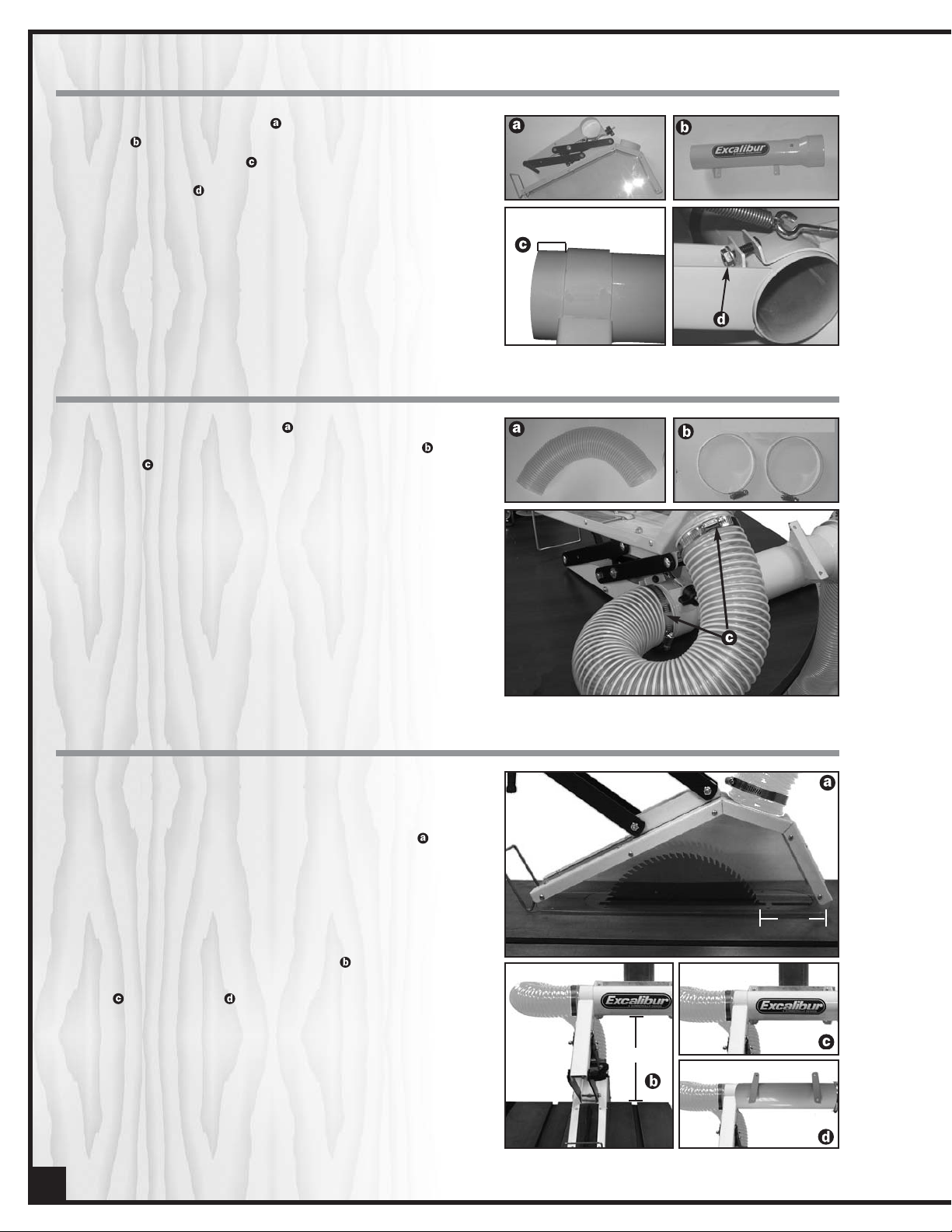
MOUNT THE HOOD ASSEMBLY TO THE BOOM ASSEMBLY
1. Slide the hood assembly over the end of the
boom leaving approximately 1” of the boom protruding past the mount .
2. Tighten the nut to secure the hood assembly to
the boom.
1”
Approximately 1” protruding for
hose installation
INSTALL THE DUST COLLECTION HOSE
Install the dust collection hose between the hood
and the boom using the two supplied hose clamps
as shown in .
MOUNT THE ASSEMBLY
1. Raise the saw blade to its full upper position and set
the complete EXBC-CM assembly on the saw table
so that the hood covers the blade. The back of the
hood should be 3” to 4” behind the saw blade .
The blade should be able to tilt to 45° without touching the side lenses. This will determine the mounting
position of the boom tube relative to the saw.
2. Devise a means of mounting the boom . It should
be mounted horizontally, with the underside of the
boom 14 1/2” above the saw table . The boom
may be rotated so the mounting brackets are vertical or horizontal . It may be suspended from
the ceiling using any convenient pipe, tubing or
lumber. If the ceiling is quite high, some form of
bracing or guy wires may be necessary to provide
stability.
Note: Make sure your support column (pipe, tube,
lumber etc.) is properly secured to a structural member such as a beam or joist.
3” to 4”
14 1/2”
6
Page 7

ADJUSTMENTS
1.
The resistance or balance of the hood assembly
can be adjusted with the spring knob located on
the rear of the hood assembly.
2. The balance of the hood can also be affected by
changing the preload exerted on it by the hose. To
do this, loosen the hose clamp that secures the
hose to the inner boom and rotate the hose on the
boom. Rotating the hose clockwise will tend to lift
the hood, while rotating it counter clockwise will
push the hood down towards the table.
3. The hood may be locked in any position by tightening the hood lock handle located on the right
side of the hood.
CONNECT TO A DUST COLLECTOR
BEFORE STARTING THE TABLE SAW, CONNECT TO A DUST COLLECTION SYSTEM.
ALWAYS TURN ON THE DUST COLLECTOR BEFORE STARTING THE TABLE SAW AND ALWAYS STOP THE TABLE SAW
BEFORE TURNING OFF THE DUST COLLECTOR.
• Connect a 4” dust hose (not included) from
your dust collector to the boom assembly.
• Check that all connections are sealed tightly to
minimize airborne dust.
• If you do not already own a dust collection system
consider contacting your GENERAL® INTERNATIONAL distributor for information on our complete line
of dust collection systems or visit our Web Site at:
www.general.ca.
7
Page 8

18
18
24
21*
20-1
20-1
23
25*
3
21*
20-1
26
20-1
19
3
51
47
5
9
35
6
2
5
9
3
4
1
6
9
15
3
4
4
3
12
8
4
7
16
10
11
2
14
13
27
17
53
47
52
4
47
51
53
54
50-EXBC-CM10/14
55
56
57
53
8
Page 9

9
*ALL PARTS ARE INTERCHANGEABLE BETWEEN EXBC-CM10 & EXBC-CM14, EXCEPT WHERE SPECIFIED.
PARTS LIST
50-EXBC-CM10 & 14
PART N0. DESCRIPTION SPECIFICATION QTY
50EXBC10-01 HOSE 3” X 720MM 1
50EXBC10-02 HOSE CLAMP 3.5” 2
50EXBC10-03 LOCK NUT 1/4” X 5MM 7
50EXBC10-04 LOCK NUT M5 4
50EXBC10-05 CARRIAGE BOLT 1/4” X 2- 1/4” 3
50EXBC10-06 PLASTIC WASHER 8
50EXBC10-07 SWING ARM 1
50EXBC10-08 HEX. HEAD BOLT M5 X 45MM 1
50EXBC10-09 HEX. HEAD BOLT 1/4” X1/2” 4
50EXBC10-10 LOCK KNOB 1/4” 1
50EXBC10-11 WASHER 1/4” X18MM 11
50EXBC10-12 EYE BOLT 1
50EXBCCM10-13 BOOM 1
50EXBCCM10-14 CONNECTING TUBE 1
50EXBC10-15 SPRING 1
50EXBC10-16 HEX. HEAD BOLT 1/4” X 1-1/4” 1
50EXBCCM10-17 PHILLIPS HEAD SCREW 3/16"X3/8" 1
50EXBC10-18 CONNECTING PLATE 4
50EXBC10-19 LOCK HANDLE 1/4” 1
50EXBC10-20-1 RIVET 16
50EXBC10-21 SIDE LENS 2
50EXBC14-21* SIDE LENS (EXBC-CM14 ONLY) 2
50EXBC10-23 TOP LENS 1
50EXBC10-24 BUMPER HANDLE 1
50EXBC10-25 HOOD FRAME 1
50EXBC14-25* HOOD FRAME (EXBC-CM14 ONLY) 1
50EXBC10-26 REAR LENS 1
50EXBCCM10-27 HOSE CLAMP 4” 1
50EXBC10-35 HOOD MOUNT 1
50EXBC10-47 WASHER M5 X 16 X 1.0T 4
50EXBC10-51 CONNECTING PLATE 2
50EXBC10-52 HANGER 1
50EXBC10-53 HEX. HEAD BOLT M5 X 10MM 3
50EXBC10-54 PLASTIC TUBE 2
50EXBC10-55 BUMPER HANDLE PLATE 2
50EXBC10-56 LOCK NUT M5 2
50EXBC10-57 SCREW M5X10 2
Page 10

IMPORTANT: When ordering replacement parts, always give the model number, serial number of
the machine and part number. Also a brief description of each item and quantity
desired.
50-EXBC-CM10/14
8360, Champ-d’Eau, Montreal (Quebec)
Canada H1P 1Y3
Tel.: (514) 326-1161
Fax : (514) 326-5565
Parts & Service
Fax : (514) 326-5555 Order Desk
orderdesk@general.ca
www.general.ca
 Loading...