

Page 1

(;%DQG(;%&DUWULGJH7DSH
6XEV\VWHP
6WDQGDUGDQGDQGH;WHQGHGOHQJWKFRQILJXUDW LRQV
,QVWDOODWLRQDQG
2SHUDWLRQ
302967-001
Page 2

Copyright
Copyright 1993-1994 by Exabyte Corporation. Allrights reserved. This
item and the information contained herein are the property of Exabyte
Corporation. No part of this document may be reproduced,
transmitted, transcribed, stored in a retrieval system, or translated into
any language or computer language in any form or by any means,
electronic, mechanical, magnetic, optical, chemical, manual, or
otherwise, without the express written permission of EXABYTE
Corporation, 1685 38th Street, Boulder, Colorado 80301.
Disclaimer
EXABYTE Corporation makes no representation or warranties with
respect to the contents of this document and specifically disclaims any
implied warranties of merchantability or fitness for any particular
purpose. Further, EXABYTE Corporation reserves the right to revise
this publication without obligation to notify any person or
organization of such revisions or changes.
Trademark Notices
AMP is a trademark of AMP Incorporated. Beckman Industrial is a
trademark of Emerson Electric Company. Dale is a registered
trademark of Dale Electronics, Inc. dataMate is a registered trademark
of Methode Electronics, Inc. EXABYTE is a registered trademark and
EXATAPE is a trademark of Exabyte Corporation. Molex is a
registered trademark of Molex Incorporated. All other product names
are trademarks or registered trademarks of their respective companies.
Revision History
Revision Date Description
000 August 1993 Initial release
001 May 1994 Updated to add information about
the eXtended-Length (XL) tape
drives and the 160m XL 8mm tape
EXABYTE Corporation
1685 38th Street
Boulder, CO 80303
Phone: (303) 442-4333
Fax: (303)442-7170
302967-001
2
EXB-8205 and EXB-8505 (Standard and XL) 302967
Page 3

Product Warranty Caution
The EXB-8205, EXB-8205XL, EXB-8505, and EXB-8505XL 8mm
Cartridge Tape Subsystems (tape drives) are warranted to be free from
defects in materials, parts, and workmanship and will conform to the
current product specifications upon delivery. For the specific details
of your warranty, refer to your sales contract or contact the company
from which the tape drive was purchased.
The warranty for the tape drive shall not apply to failures caused by:
■
Physical abuse or use not consistent with the operating
instructions or product specifications provided by Exabyte’s
personnel or agent for the applicable equipment.
■
Modifications by other than Exabyte’s personnel or agent in any
way other than those approved by Exabyte, provided the
warranty shall not be voided by the repair or replacement of
parts or the attachment of items in the manner described in
maintenance or installation instructions provided by Exabyte.
■
Repair by other than Exabyte’s personnel or agent in a manner
contrary to the maintenance instructions provided by Exabyte.
■
Removal of the Exabyte serial number tag.
■
Physical abuse due to improper packaging of returns.
CAUTION
Returning the tape drive in unauthorized packaging may
damage the unit and void the warranty. Refer to the packing
instructions in this book for information.
If problems with the tape drive occur, contact your maintenance
organization; do not void the product warranty by allowing untrained
or unauthorized personnel to attempt repairs.
May 1994 EXB-8205 and EXB-8505 (Standard and XL)
3
Page 4

Contents
Welcome ............................5
AboutThisGuide .......................6
ConventionsUsedinThisGuide .................6
ForMoreInformation .......................6
1Installingthetapedrive...................7
Unpacking and Handling the tape drive . . . . . . . . . . . . . . 8
SettingtheSCSIID........................9
Preparing the Tape Drive for the SCSI Bus . . . . . . . . . . . 11
InstallingtheTapeDriveinaComputer ............13
PerformingtheInitialPowerOn.................18
2Operatingthetapedrive .................20
SelectingDataCartridges....................23
Setting the Write-Protect Switch on a Data Cartridge ...25
Loading a Data Cartridge in the tape drive . . . . . . . . . . . 26
UnloadingaDataCartridge...................27
3PreventiveMaintenance .................28
Determining When to Clean the Tape Drive . . . . . . . . . . 28
Usingthe8mmCleaningCartridge...............29
Caring for Data Cartridges . . . . . . . . . . . . . . . . . . . 30
4ShippingtheTapeDrive .................32
PackingtheTapeDrive.....................33
Environmental Requirements for Shipment . . . . . . . . . . . 35
Appendix A Installation Requirements ..........36
SCSICable...........................36
SCSI Connector . . . . . . . . . . . . . . . . . . . . . . . . . 37
Power Supply . . . . . . . . . . . . . . . . . . . . . . . . . . 38
Power Connector . . . . . . . . . . . . . . . . . . . . . . . . 38
Attaching the tape drive to a Frame . . . . . . . . . . . . . . 39
Chassis Grounding (Optional) . . . . . . . . . . . . . . . . . 41
AppendixBUnloadButtonOptions............ 42
AppendixCTapeDriveSpecifications .......... 44
Index .............................45
4
EXB-8205 and EXB-8505 (Standard and XL) 302967
Page 5
W
elcome
Thank you for selecting the Exabyte®EXB-8205,
EXB-8205XL, EXB-8505, or EXB-8505XL8mm Cartridge Tape
Subsystem (tape drive). These tape drives are high-capacity,
high-performance, and highly reliable storage devices for
PC, workstation, and local area network (LAN) applications.
The “eXtended-Length” (XL) configurations of the tape
drives (EXB-8205XL and EXB-8505XL) provide additional
capacity by supporting the extended-length EXATAPE™
160m XL 8mm Data Cartridge. Information about the 160m
XL data cartridge is provided on page 24.
May 1994 EXB-8205 and EXB-8505 (Standard and XL)
5
Page 6

About This Guide
Use this guide as you install and operate the tape drive. In
addition to instructions for installation and operation, this
guide provides information about selecting and maintaining
data cartridges, cleaning the tape drive, and packing the tape
drive for shipment.
Conventions Used in This Guide
Special information is highlighted as follows:
Note: Notes provide hints or suggestions about the topic
or procedure being discussed.
Important
Information in Important boxes will help you
successfully complete a procedure or avoid
additional steps in a procedure.
CAUTION
Information in Caution boxes explains how to avoid
damaging the tape drive, the data cartridge, other
equipment, or data recorded on tape.
For More Information
For tape drive specifications, refer to the EXB-8205 and
EXB-8505 Product Specification for Standard and
eXtended-Length Configurations (510504). For information
about programming SCSI commands for the tape drive, refer
to the EXB-8205 and EXB-8505 SCSI Reference for Standard
and eXtended-Length Configurations (510503). For
information about integrating the tape drive into a host
system, refer to EXB-8205 and EXB-8505 Integration and
Optimization for Standard and eXtended-Length Configurations
(510505).
6
EXB-8205 and EXB-8505 (Standard and XL) 302967
Page 7
1 Installing the tape drive
This section provides instructions for the following tasks:
■
Unpacking and handling the tape drive (page 8)
■
Setting the SCSI ID (page 9)
■
PreparingthetapedrivefortheSCSIbus (page11)
■
Installing the tape drive in a computer (page 13)
■
Performing the initial power on (page 18)
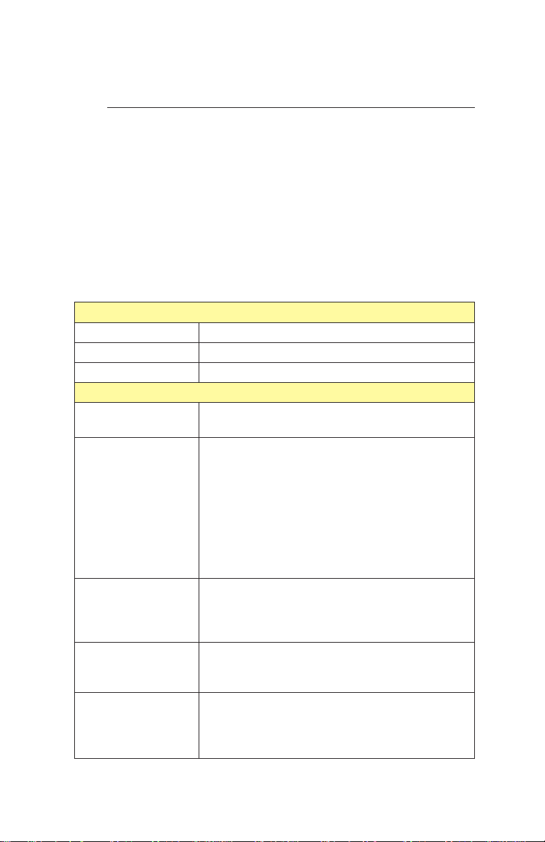
Table 1 lists the tools and equipment you will need.
Table 1 Tools and equipment for installing the tape drive
Required Tools and Equipment
SCSI cable
Power cable
Power supply
Remote switch
or jumpers
External SCSI
bus terminator
Mounting frame
or brackets, four
M3 5 6 mm
screws, screwdriver
Flat-nose
wiring pliers
1
⁄4-inch female
spade connector
or M3-0.5 6 mm
self-tapping screw
See page 36 for SCSI cable requirements.
See page 36 for power cable requirements.
See pages 38-38 for power specifications.
Optional Tools and Equipment
Ifyouusearemoteswitch,useafemaleMolex
22-55-2061 (or equivalent) cable connector.
Differential: If the tape drive terminates the
SCSI bus, you must provide a Methode
Electronics, Inc. dataMate®DM103-01-0 (or
equivalent) differential external terminator.
Single-ended: If the tape drive terminates the
SCSI bus, you have the option of removing the
tape drive’s internal terminators (R-packs) and
using a dataMate DM103-02-0 (or equivalent)
single-ended external terminator.
Depending on your installation requirements,
can be used to mount the tape drive.
Can be used to remove the R-packs from a
single-ended tape drive that uses an external
terminator or does not terminate the SCSI bus.
Can be used for additional chassis grounding.
®
May 1994 EXB-8205 and EXB-8505 (Standard and XL)
7
Page 8

Unpacking and Handling the tape drive
The tape drive’s packaging is designed to protect the tape
drive from shock, vibration, moisture, and electrostatic
discharge (ESD). Save all original packaging in case you
need to repack or ship the tape drive.
If the temperature of the room in which you are unpacking
the tape drive varies from the storage location by 15° C(27°
F) or more, let the tape drive acclimate in its packaging to
the unpacking environment for at least 12 hours before
opening the box.
After you unpack the tape drive, check the contents of the
carton against the packing list and inspect the tape drive for
possible damage. If a part is missing or the tape drive is
damaged, notify the carrier and your vendor immediately.
Note: If the tape drive has been stored for more than six
months, follow the instructions on page 18 when
applying power for the first time. (Check the
MLCH label on the top of the tape drive to find
out when the tape drive was manufactured.)
CAUTION
Follow these procedures to protect the tape drive
from electrostatic discharge:
■
Leave the tape drive in its antistatic bag until you
are ready to install it.
■
Use an antistatic mat and grounded static
protection wristband. If a mat and wristband are
unavailable, discharge static electricity from your
body before handling the tape drive. (Touch a
known grounded surface, such as your
computer’s metal chassis.)
■
If you must lay the tape drive down, place it into
or on top of the antistatic bag.
8
EXB-8205 and EXB-8505 (Standard and XL) 302967
Page 9
Setting the SCSI ID
After you have unpacked the tape drive, you can set the tape
drive’s SCSI ID. You can use either of the following methods:
■
Attach jumpers (shunts) to the pins on the tape
drive’s SCSI ID jumper block. Jumpers are already
installed on the jumper block when the tape drive is
shipped.
■
Connect a remote switch to the SCSI ID jumper block
on the back of the tape drive.
Setting the SCSI ID with Jumpers
To set the SCSI ID using jumpers, follow these steps:
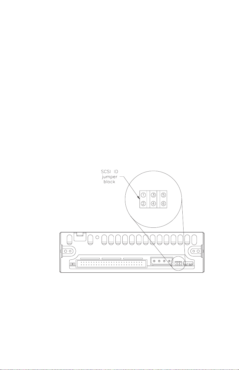
1. Locate the SCSI ID jumper block on the back of the
tape drive, as shown in Figure 1.
Figure 1 SCSI ID jumper block on the back of the tape
drive
2. Remove the jumpers from the jumper block to
obtain the correct address for your configuration.
Figure 2 shows how to position the jumpers for
addresses 0 through 7.
May 1994 EXB-8205 and EXB-8505 (Standard and XL)
9
Page 10

Figure 2 Jumper settings for the tape drive’s SCSI ID
Setting the SCSI ID with a Remote Switch
If you want to set the SCSI ID remotely, you can attach a
remote switch assembly (not provided with the tape drive)
to the tape drive’s SCSI ID jumper block. To set the SCSI ID
with a remote switch, follow these steps:
1. Locate the SCSI ID jumper block on the back of the
tape drive, as shown in Figure 1.
2. If necessary, remove the jumpers from the pins.
3. Connect a remote switch to the jumper block.
Ensurethattheremoteswitchisnomorethan
30.5 cm (12 inches) from the jumper block.
4. Change the settings on the remote switch to the
correct address for your configuration. The switch
settings should emulate the jumper positions
shown in
Figure 2.
Note: For specific information about pin assignments
for the SCSI ID jumper block, refer to the
EXB-8205 and EXB-8505 Product Specification for
thetapedrive.
10
EXB-8205 and EXB-8505 (Standard and XL) 302967
Page 11

Preparing the Tape Drive for the SCSI Bus
The SCSI bus that you attach the tape drive to must be
terminated correctly to ensure proper operation. The devices
that are physically located at each end of the SCSI cable must
have terminators installed. All other devices on the SCSI
cable must not have terminators installed.
IfyouplacethetapedriveattheendoftheSCSIbus,you
must terminate the tape drive. The procedure you use
depends on whether the tape drive uses a single-ended or a
differential SCSI configuration.
Termination for a Single-Ended tape drive
The single-ended tape drive includes three single in-line
package (SIP) resistor terminators (R-packs) that can be left
in place if the tape drive terminates the SCSI bus.
CAUTION
The R-packs must be removed if the tape drive does
not terminate the SCSI bus or if external SC SI bus
termination will be used. Instructions for removing
the R-packs are provided below.
Optional External Termination
If desired, you can terminate the single-ended tape drive
externally by removing the R-packs from the back of the
tape drive and installing an external terminator. Exabyte
recommends a Methode Electronics, Inc. dataMate
DM103-02-0 single-ended external terminator.
Removing the R-Packs
To remove the R-packs, follow these steps:
1. Locate the three R-packs on the back of the tape
drive, as shown in Figure 3.
2. Using a pair of flat-nose wiring pliers, grasp each
R-pack in the center and pull it straight out. Be
careful not to squeeze the pliers too tightly or you
may break the R-pack.
May 1994 EXB-8205 and EXB-8505 (Standard and XL)
11
Page 12
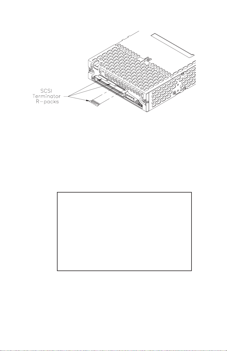
Figure 3 Location of R-packs on the back of the tape drive
(single-ended configuration)
Replacing the R-Packs
If you need to put the R-packs back in the tape drive, make
sure that pin 1 of each R-pack is aligned with pin 1 of the
socket and that no pins are bent. As shown in Figure 3, the
writing on the R-pack should face upward. Pin 1 of the
R-pack is marked with a colored line or dot and should line
up with the right side of the socket.
CAUTION
If you replace an R-pack, be sure to use the correct
type to avoid damaging the tape drive. Use an
8-pin, 6-resistor SIP terminator, rated at 220/330
ohms. Exabyte recommends either of the following
terminators (or equivalent):
■
Dale®: part number CSC 08A-05-221/331J
■
Beckman Industrial™: part number
L08-5C221/331J
Termination for a Differential tape drive
The differential tape drive does not include internal
terminators. If a differential tape drive terminates the SCSI
bus, it must be terminated externally. See page 7 for
information about the recommended terminator.
12
EXB-8205 and EXB-8505 (Standard and XL) 302967
Page 13
Connecting the SCSI Cable
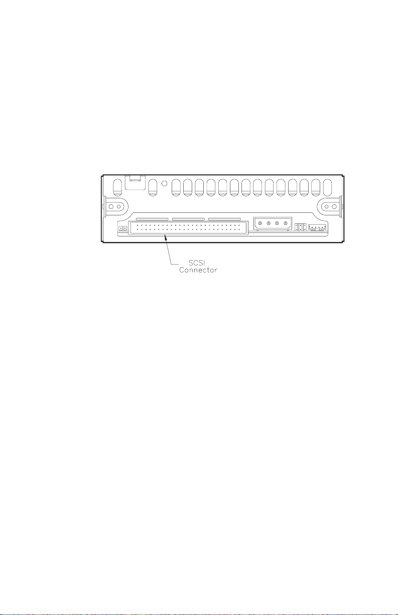
After removing or installing terminators as required, connect
the SCSI cable to the SCSI connector on the back of the tape
drive. The connector is keyed so that it can be connected
only one way.
Figure 4 shows the location of the SCSI connector. See
Appendix A starting on page 36 for information about the
requirements for the SCSI cable.
Figure 4 Location of SCSI connector
Installing the Tape Drive in a Computer
If you are installing the tape drive in a drive bay in a
computer system, follow the guidelines in this section.
Otherwise, refer to Appendix A for general installation
requirements. Then, turn to page 18 to perform the initial
power on.
Preparing the Computer System
Before installing the tape drive in your computer system,
prepare the system as follows:
1. Turn off the computer and any attached devices.
2. Unplug the computer’s power cord.
3. Remove the computer’s cover as described in your
computer system documentation.
May 1994 EXB-8205 and EXB-8505 (Standard and XL)
13
Page 14

4. If there is a cover plate over the drive bay you plan
to use, remove it. Refer to your computer system
documentation for instructions. Keep any screws or
mounting clips; you may need them to secure the
tape drive to the drive bay.
Note: If necessary, remove a floppy disk drive to
provide an empty half-high drive bay for the
tape drive. Refer to your computer system
documentation for instructions. Do not
replaceyourfloppydriveAwiththetape
drive.
Important
If you remove a floppy disk drive to ins tall the tape
drive, be sure to change your system configuration
filestoreflectthechange.Refertoyourcomputer
system documentation for instructions.
Installation Procedure
Follow these steps to install the tape drive in the drive bay:
1. Check for the presence of a load resistor in your
computer. If it is present, disconnect the load
resistor cable from the power supply. Refer to your
computer system documentation for more
information.
14
2.
Use #6 32 screws to attach two slide rails to the
sides of the tape drive as shown in Figure 5. You
can use rails that are provided with your computer
system or purchase rails from Exabyte or your
computer supplier.
Note: If there is more than one set of mounting
holes in the rails, use whichever set allows
you to position the tape drive flush with the
front of the drive bay.
EXB-8205 and EXB-8505 (Standard and XL) 302967
Page 15
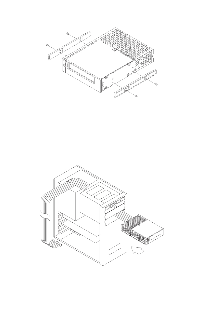
Figure 5 Attaching slide rails to the tape drive
3. From the front of the computer, thread the SCSI
cable through the open drive bay, as shown in
Figure 6. Slide the tape drive into the bay until the
frontofthedriveisflushwiththefrontofthedrive
bay.
4. Connect the SCSI cable to the SCSI adapter card in
your computer.
Figure 6 Inserting the drive into the drive bay and connecting the
SCSI cable to the adapter card
May 1994 EXB-8205 and EXB-8505 (Standard and XL)
15
Page 16
5. Slide the tape drive into the drive bay and secure
the drive to the bay as instructed in you computer
system documentation.
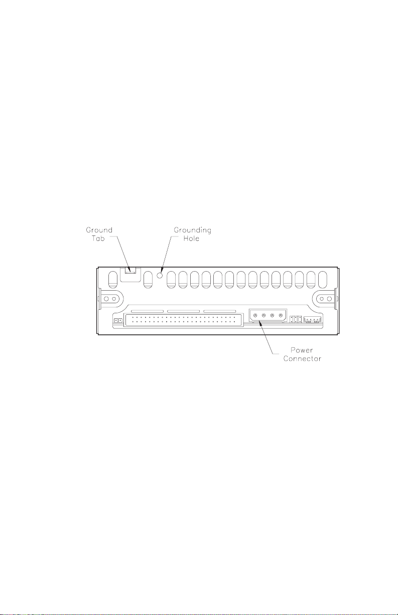
6. If you needed additional chassis grounding,
connect a
ground tab at the rear of the tape drive. Or, connect
an M3-0.5 6 mm self-tapping screw to the
grounding hole. The ground tab and grounding
hole are shown in Figure 7.
Note: The power supply returns are connected to
Figure 7 Location of ground tab, grounding hole, and
1
⁄4-inch female spade connector to the
the chassis, so you cannot isolate logic
common ground from chassis ground.
power connector on the back of the CTS
16
EXB-8205 and EXB-8505 (Standard and XL) 302967
Page 17
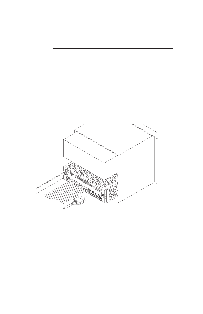
7. Locatethepowerconnectoronthebackofthetape
drive. Connect the power cable to the power
connector as shown in Figure 8.
CAUTION
The power cable plug and the power connector are
keyed so they can fit together in only one way.
Before connecting the plug to the tape drive, be
sure that the beveled edges of the plug are oriented
in the same way as the beveled edges on the power
connector. Do not force the plug into the connector
or you may damage the tape drive.
8. Replace the cover on your computer.
Figure 8 Connecting the power cable to the tape drive
May 1994 EXB-8205 and EXB-8505 (Standard and XL)
17
Page 18

Performing the Initial Power On
The procedure you use to perform the initial power on
depends on how long the tape drive has been stored. If you
are not sure how long the tape drive has been stored, check
the MLCH (machine level control history) label on the top of
the tape drive to find out when the tape drive was
manufactured. Although the tape drive may have been
operated since it was manufactured, for the purpose of the
initial power on, assume that it has been stored throughout
this period.
Tape Drive Stored for Less Than Six Months
If the tape drive has been stored for less than six months, the
only step you need to perform for the initial power-on is to
apply power to the tape drive.
When power is applied, the tape drive performs its
power-on initialization and self-test (POST). Assuming that
no data cartridge is loaded and that the tape drive is
connected correctly, POST takes about 32 seconds, as follows:
■
During the first part of POST, all three LEDs are lit.
■
During the second part of POST, the top LED is lit
and the middle and bottom LEDs may flash,
depending on whether the tape drive is connected to
the SCSI bus and a data cartridge is loaded.
18
When POST completes (top LED off), the tape drive is ready
for normal operation.
Important
■
Do not insert a data cartridge into the tape drive
while POST is occurring. The tape drive will eject it.
■
If the top LED does not go out after POST, an
error has occurred. Contact your vendor.
EXB-8205 and EXB-8505 (Standard and XL) 302967
Page 19

Tape Drive Stored for Six Months or More
If the tape drive has been stored for six months or more,
perform the following steps using your backup software to
ensure that the tape drive’s internal lubrication is properly
distributed:
1. Apply power to the tape drive. T he tape drive
performs its POST as described on page 18.
2. Locate a test tape and ensure that the write-protect
switch is set to permit data to be written to the tape
(see page 25).
3. Insert the data cartridge into the tape drive with the
labelsideupandthewrite-protectswitchfacing
you.
4. Waitwhilethetapedriveloadsthetapeand
positions it to the logical beginning of tape (LBOT).
This takes about 40 seconds. When the bottom LED
is on solid, the tape drive is ready.
5. Perform a backup operation to write approximately
500 MB of data to the tape.
6. Rewind the tape and read the data written in step 5.
7. Repeat steps 5 and 6 at least two times or for two
hours (whichever is greater).
Note: If errors occur, reset the tape drive and
repeat steps 5 though 7 as appropriate.
When you have completed step 7, the tape drive is ready for
normal operation.
May 1994 EXB-8205 and EXB-8505 (Standard and XL)
19
Page 20
2 Operating the tape drive
This section includes information about the following:
■
Reading the LEDs
■
Selecting data cartridges
■
Setting the write-protect switch on the data cartridge
■
Loading and unloading a data cartridge
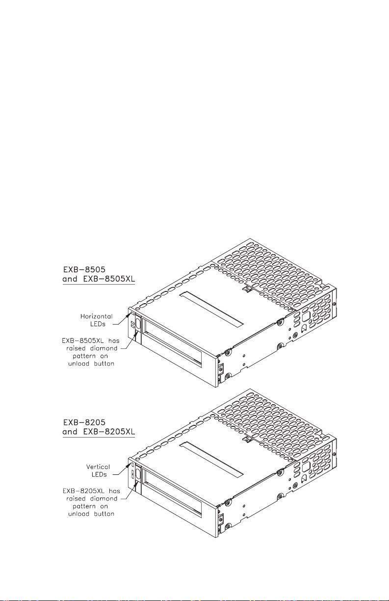
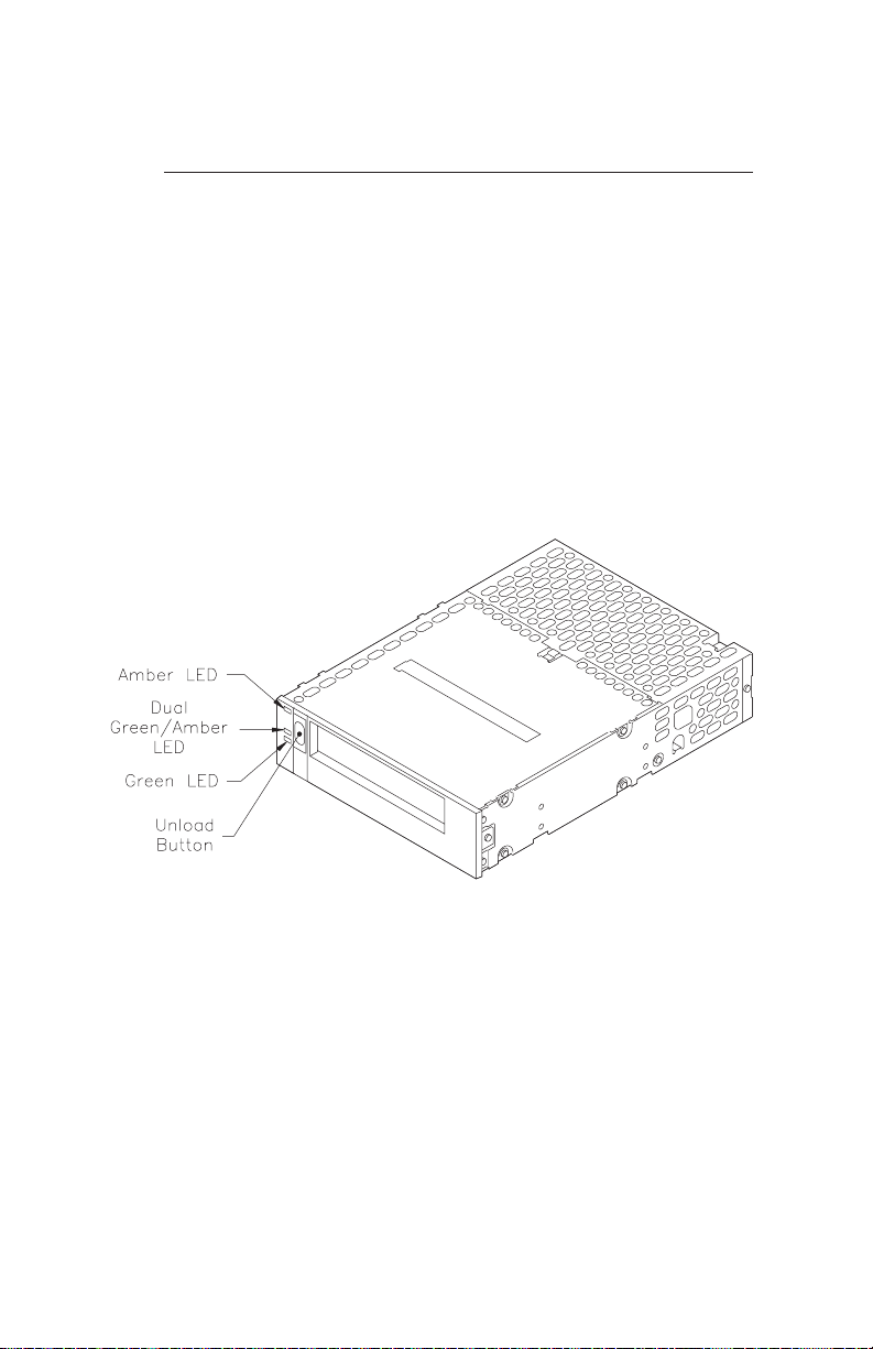
Figure 9 shows the controls and indicators on the front panel
of the EXB-8505. (Note that the front panel of the EXB-8205
is the same except the LEDs are vertical. The XL drives are
the same as the non-XL drives except that they have a raised
diamond pattern on the unload button.)
Figure 9 Unload button and LEDs on the ta pe drive’s front panel
20
EXB-8205 and EXB-8505 (Standard and XL) 302967
Page 21

Reading the LEDs
The tape drive uses three LEDs to indicate its operating
states. The LEDs indicate the following general conditions:
■
When the top (amber) LED is flashing, the tape
drivehasanerrororneedstobecleaned.
■
When the middle LED is on or flashing, SCSI bus
activity is occurring. The middle LED can be green or
amber, as follows:
Amber: The tape loaded in the tape drive is in one of
the compression formats (8500c or 8200c).
Note that when the tape is in 8500c format,
the LED is always amber even though
compression can be turned off.
Green: The tape loaded in the tape drive is in one of
the non-compression formats (8500 or 8200).
■
When the bottom (green) LED is on, a data cartridge
isloadedinthetapedrive.WhenthisLEDis
flashing, tape motion is occurring.
Table 2 shows specific combinations of LEDs that may occur
during tape drive operation.
Note: You may occasionally observe LED combinations
and sequences not described in Table 2. These
other combinations represent special or unusual
conditions that are beyond the scope of this table.
(For example, a fairly complex LED sequence
occurs when you load new microcode from tape.)
May 1994 EXB-8205 and EXB-8505 (Standard and XL)
21
Page 22
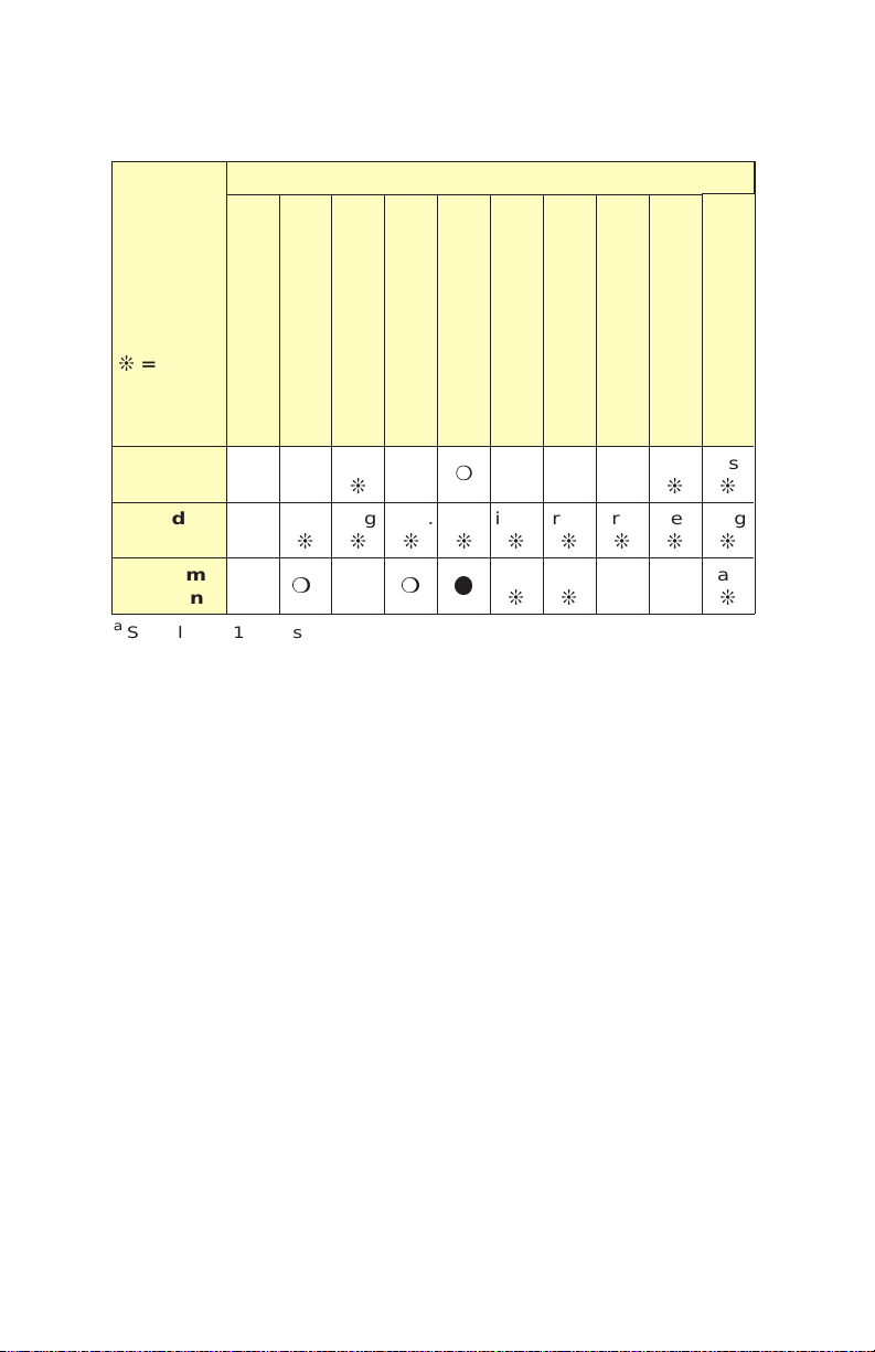
Table 2 tape drive states indicated by the LEDs
Tape Drive State
LEDs
● =On
❍=Off
Top
a
POST (start)
POST (end)
Failed POST
Ready (no tape loaded)
Ready (tape loaded)
Normal tape motion
High-speed tape motion
SCSI bus reset
●●
green●irreg.jirreg.jirreg.jirreg.jirreg.jirreg.jirreg.jirreg.jirreg.
b
●
fast
mc❍
❍❍❍❍●
j
ml
slowjfast
j
●❍
j
=Flash
(errors)
Middle
(SCSI)
Bottom
(motion)
a
Slow flash = 1 flash/second (0.94 Hz).
Fast flash = 4 flashes/second (3.76 Hz).
Irregular flash = variable rate depending on SCSI bus activity. If the
tape drive is not connected to the SCSI bus, the LED will be off.
b
Green_8500 or 8200 format.
Amber_8500c or 8200c format.
c
If a tape is loaded, the bottom LED will flash slow and then fast during
the second part of the power-on self-test.
Error
slowjfast
j
j
fast
j
Time to Clean
22
EXB-8205 and EXB-8505 (Standard and XL) 302967
Page 23

Selecting Data Cartridges
By selecting high-quality data cartridges and storing them
properly, you can expect a long shelf-life and optimal data
integrity from your tapes. High quality tapes also help
maintain tape drive reliability by minimizing wear on the
recording heads.
Choosing High-Quality Data Cartridges
Available from Exabyte, EXATAPE™ 8mm Data Cartridges
are formulated specifically for use in Exabyte products.
EXATAPE data cartridges reduce head and tape path wear
and have a shelf life exceeding 30 years when used
according to recommendations.
Available in lengths of 15m, 54 m, 112m, and 160m (for the
EXB-8205XL and EXB-8505XL only, as described on page24),
EXATAPE data cartridges are the only data cartridges
recommended for use with all Exabyte products.
CAUTION
Never use video-grade tape for data storage.
Video-grade tape can be less accurate than
data-grade tape when recording high-density data
andmoreabrasivetotapedriverecordingheads.In
particular, Exabyte strongly discourages use of the
following types of video-grade tapes:
7 Extended-length video tapes (such as 135-, 140-,
and 150-minute tapes)
7 Hi-8 metal particle (MP), metal evaporative
(ME), or barium ferrite (BaFe) tapes
May 1994 EXB-8205 and EXB-8505 (Standard and XL)
23
Page 24
EXATAPE 160m XL 8mm Data Cartridges
The EXATAPE 160m XL 8mm Data Cartridge is intended for
use in the EXB-8502XL and EXB-8505XL only. The 160m XL
tape is equipped with a Recognition System stripe, located
onthetapeleader,thatenablestheXLtapedrivetorecognize
the tape as data-quality metal-particle media. To prevent the
use of inappropriate media, the EXB-8205XL and EXB-8505XL
do not accept 160m tapes without the Recognition System
stripe. If you attempt to load a 160m tape without this stripe,
the XL tape drive automatically ejects it.
The EXB-8205 and EXB-8505 do not support the 160m XL
tape. If you attempt to load any 160m data cartridge into an
EXB-8205 or EXB-8505, the tape drive automatically ejects
the cartridge.
CAUTION
Do not attempt to use the 160m XL Data Cartridge in
the following Exabyte tape drives: EXB-8200,
EXB-8200SX, EXB-8500, or EXB-8500c. Although these
drives will accept the 160m XL cartridge, these
cartridges are not supported by these drives and
should not be used.
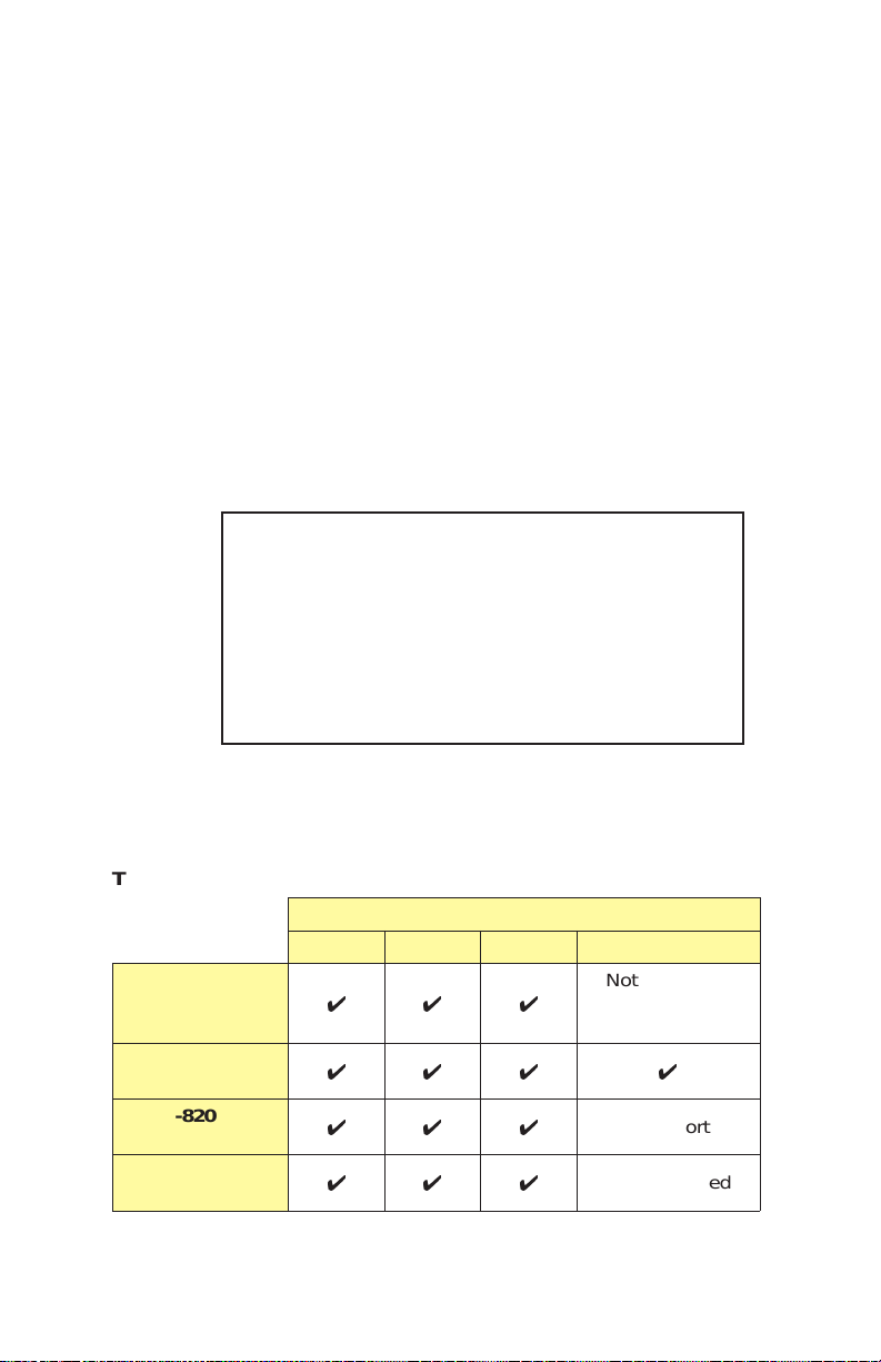
Compatibility of EXATAPE 8mm Data Cartridges
Table 3 summarizes the compatibility of EXATAPE 8mm
Data Cartridges with Exabyte 8mm tape drives.
Table 3 Compatibility of EXATAPE 8mm Data Cartridges and
EXATAPE 8mm Data Cartridge
15m 54m 112m 160m XL
EXB-8205
and
EXB-8505
EXB-8205XL and
EXB-8505XL
EXB-8200 and
EXB-8200SX
EXB-8500 and
EXB-8500c
24
444
444 4
444
444
EXB-8205 and EXB-8505 (Standard and XL) 302967
Not supported
(automatically
ejected)
Not supported
Not supported
Page 25
Setting the Write-Protect Switch on a Data Cartridge
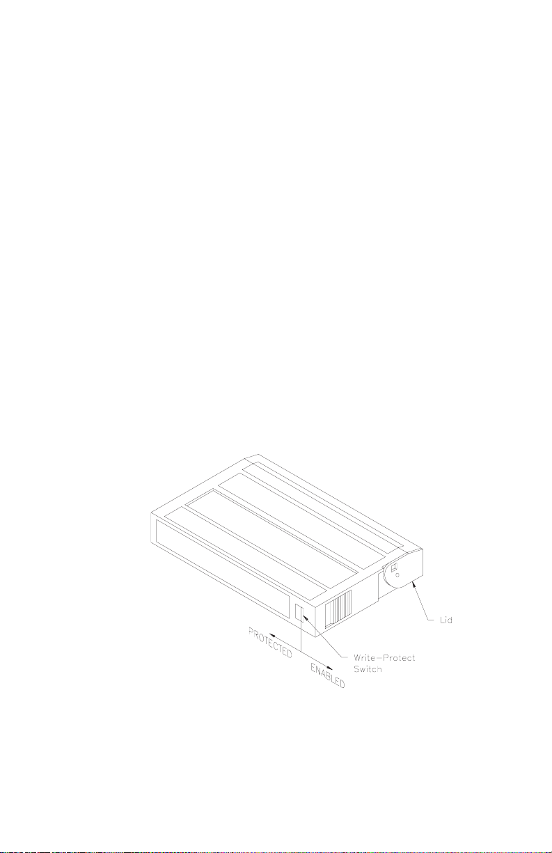
EXATAPE™ 8mm data cartridges are equipped with a
write-protect switch, shown in Figure 10, to prevent data on
the tape from being unintentionally overwritten.
Before loading a data cartridge in the tape drive, ensure that
the write-protect switch is set correctly for the desired
operation. You can use a ball-point pen or similar
instrument to set the write-protect switch as follows:
■
To write protect the data cartridge, move the
write-protect switch away from the edge of the data
cartridge. If the red tab is visible, the cartridge is
write protected and cannot be written to or erased.
■
To write enable the data cartridge, move the
write-protect switch toward the edge of the data
cartridge. If the red tab is not visible, the data
cartridge is write enabled and can be written to or
erased.
Figure 10 Write-protect switch on an EXATAPE
8mm data cartridge
May 1994 EXB-8205 and EXB-8505 (Standard and XL)
25
Page 26

Loading a Data Cartridge in the tape drive
Important
Exabyte strongly recommends that you use
EXATAPE™ data-grade metal-particle media in the
tape drive. Refer to page 23 for information about
selectingappropriatetapesforyourtapedrive.
To load a data cartridge into the tape drive, follow these
steps:
1. Ensure that the write-protect switch has been set
correctly for the desired operation, as explained on
page 25.
2. Ifyouhavejustpoweredonthetapedrive,besure
that the bottom and top LEDs are off, indicating
that the tape drive has passed its power-on self-test
and is ready to load the data cartridge.
3. Insert the data cartridge into the tape drive with the
lid facing toward the tape drive, the write-protect
switch facing away from the tape drive, and the
label side of the cartridge facing the top of the tape
drive.
26
4. The tape drive automatically loads the data
cartridge and positions the tape to the logical
beginning of tape (LBOT) within approximately 40
seconds (assuming that the data cartridge has
already been rewound). During this period, the
tape drive determines the tape format and the
length of the tape. All three LEDs are off for the
first 8 seconds of the load operation. Then, the
bottom LED flashes to indicate tape motion. When
the bottom LED is on solid, the tape drive is ready.
Note: If your application has disabled autoload,
the tape drive will not go to the ready state
until a LOAD (1Bh) command has been
issued by your host system.
EXB-8205 and EXB-8505 (Standard and XL) 302967
Page 27

Unloading a Data Cartridge
The unload button is the only operator control on the tape
drive. It is used to unload the tape from the tape drive. The
unload button can also be used to clear servo and other
errors. If a servo or hardware error occurs, press the unload
button to reset the tape drive. Then, if necessary, wait a few
seconds and press the button again to eject the tape.
Unload Procedure
To unload a data cartridge, press the unload button on the
tape drive’s front panel. The tape drive completes the
current operation, writes any buffered data to the tape,
rewinds the tape, unloads the tape from the tape path, and
ejects the cartridge.
Notes:
■
Some tape drives are configured to eject the tape
immediately, without completing the current
operation, when the unload button is pressed. Refer
to Appendix B for more information about tape
drives configured in this way.
■
Some backup applications have features that prevent
removal of the tape. In such cases, the tape drive
performs no action when you press the unload
button.
Error During Unload Procedure
If an error exists before or during the unload procedure, the
unload sequence will be suspended and the top LED will
flash. To clear the error, press the unload button again. The
unload sequence will be reattempted; however, unwritten
data in the buffer will not be written to tape. The buffer and
errors will be cleared.
CAUTION
The first time you load a tape after resetting an
unload error, use a test tape. Make sure that the
tape drive can successfully unload the test tape
before loading a tape containing valuable data.
May 1994 EXB-8205 and EXB-8505 (Standard and XL)
27
Page 28

3 Preventive Maintenance
The only routine maintenance required by the tape drive is
regular cleaning of the tape drive’s heads and tape path. The
only cleaning material authorized for use with the tape drive
is an Exabyte or Exabyte-approved 8mm Cleaning
Cartridge. In addition, proper storage and maintenance of
your data cartridges will maximize the shelf life of you tapes
and ensure data integrity.
Important
Using a cleaning method other than the Exabyte
8mm Cleaning Cartridge or an Exabyte-approved
cleaning cartridge will void the warranty for the
tape drive and can lead to premature head wear.
Determining When to Clean the Tape Drive
You should clean the tape drive’s heads and tape path either
once a month or after every 30 tape motion hours,
whichever occurs first. This cleaning frequency does not
depend on the format in which you write and read data.
However, if you are using the tape drive in a particularly
dirty environment, or if you operate it infrequently, you
may want to clean the tape drive more often.
28
Thetapedrivekeepstrackofitstapemotionhours
internally. When 30 tape motion hours have elapsed, the top
and bottom LEDs will flash rapidly and the middle LED will
flash irregularly, depending on SCSI bus activity. For best
results, clean the tape drive as soon as possible after the
LEDs begin flashing.
Note: Some backup software programs may use
additional ways to notify you when the tape
drive needs cleaning. Refer to the documentation
for your backup software for more information.
EXB-8205 and EXB-8505 (Standard and XL) 302967
Page 29

Using the 8mm Cleaning Cartridge
Exabyte 8mm Cleaning Cartridges are available in two sizes:
3c and 12c. Used in the EXB-8205, EXB-8505, or XL tape
drives, the 3c cleaning cartridge provides up to 9 cleanings.
The 12c cleaning cartridge provides up to 36 cleanings.
Note: If you use these cleaning cartridges in an Exabyte
full-high tape drive (EXB-8200, EXB-8200SX,
EXB-8500, or EXB-8500c), you will get fewer
cleaning passes per cartridge. These tape drives
have longer tape paths than the EXB-8205,
EXB-8505, or XL tape drives, and require more
material for each cleaning.
CAUTION
To prevent contamination of the tape drive and
damage to the heads, never rewind and reuse the
cleaning cartridge.Reusingthematerialinthe
cleaning cartridge will redistribute contaminants
previously removed from the tape path.
To use the cleaning cartridge, follow these steps:
1. Apply power to the tape drive. When the power-on
self-test is complete, press the unload button and
remove any data cartridge from the tape drive.
2. Insert the cleaning cartridge in the tape drive. The
cleaning cycle is performed automatically by the
tape drive and lasts from 2 to 3 minutes. When the
cleaning cycle is complete, the cleaning cartridge is
automatically unloaded and ejected.
Important
If there are no cleaning cycles remaining for the
cleaning cartridge, the tape drive ejects it without
performing the cleaning cycle. The top and bottom
LEDs remain lit. Discard the cleaning cartridge
when no more cleaning cycles remain.
May 1994 EXB-8205 and EXB-8505 (Standard and XL)
29
Page 30

3. To confirm that a cleaning was done, check the
LEDs on the front panel. If the cleaning cycle was
successful,thetopandbottomLEDswillbeoff.If
the cleaning cycle was not performed, the LEDs
will continue to flash. Repeat the cleaning
procedure with a new cleaning cartridge.
4. If the cleaning cycle was successful, you may want
to keep a record of the date the cleaning was
performed. Store the cleaning cartridge for future
use if it still has cycles remaining. Or, discard it if
no more cleaning cycles remain.
Caring for Data Cartridges
To maximize the shelf life of your tapes and assure data
integrity, follow these guidelines when storing data
cartridges:
■
Maintain the storage environment at a constant
temperature and humidity. A temperature within
the range of +5°Cto+32°C(+41°Fto+90°F) with a
relative humidity of 20% to 60% non-condensing is
ideal for tape storage. Do not allow the temperature
and humidity in the storage environment to fluctuate.
30
■
Keep the storage location as free of airborne
particulates as possible. To eliminate obvious
sourcesofparticulates,donotpermitanyoneto
smoke, eat, or drink near the storage area, and do not
store cartridges near a copier or printer that may
emit toner and paper dust.
■
Store data cartridges as soon a s possible after you
have written data to them. Immediate storage helps
avoid many of the conditions that can damage tapes,
such as temperature and humidity fluctuation,
particulate contamination, and excessive handling.
■
Store data cartridges with the write-protect switch
in the protected position. Instructions for using the
write-protect switch are provided on page 25.
EXB-8205 and EXB-8505 (Standard and XL) 302967
Page 31
■
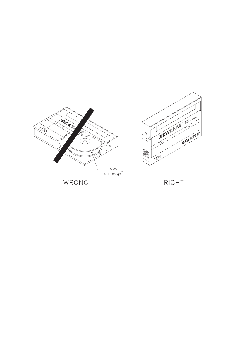
Store each cartridge on one of its long edges, not
flat on its side (see Figure 11 on the following
page). When a data cartridge is stored on its side, the
tape inside the cartridge is actually on its edge. In
this position, stress is placed on the tape edges and
can lead to tape damage. For the same reason, never
stack cartridges on top of each other or lean them at
an angle for extended periods o f time.
Figure 11 Do not store a data cartridge on its side
Replacing Data Cartridges
Approximately once each year, you may want to run each
tape through a full pass and check its error statistics. If
errors have increased significantly since the previous test or
if they exceed a certain predetermined threshold, you should
re-archive the data to a new tape and discard the old tape.
May 1994 EXB-8205 and EXB-8505 (Standard and XL)
31
Page 32

4 Shipping the Tape Drive
You can ship the tape drive with either one drive per carton
(single-pack) or with three to five drives per carton
(multi-pack). Figure 12 on page 34 shows the single-pack
carton and packing materials; Figure 13 on page 35 shows
the multi-pack carton and packing materials.
CAUTION
■
To avoid damaging the tape drive and voiding
yourwarranty,besuretousetheoriginal
shipping materials (or replacement materials
obtained from Exabyte) when repacking and
shipping the tape drive.
■
To ensure that the packaging meets the required
specifications, do not modify the packaging in
any way. The shipping carton and packing
materials are not intended to be used for shipping
items other than or in addition to a tape drive.
■
Do not use the multi-pack shipping carton for
fewer than three tape drives. If y ou are shipping
one or two tape drives, use a single-pack carton for
each tape drive.
Table 4 shows the dimensions and weights of the
single-pack and multi-pack shipping cartons.
Table 4 Dimensions and weights of tape drive shipping cartons
Size Dimensions Weight (with tape drive)
34.3 cm long
27.3 cm wide
Single-pack
Multi-pack
32
15.5 cm high
(13.5 10.75
6.12 inches)
59.1 cm long
34.3 cm wide
29.2 cm high
(23.25 13.5
11.5 inches)
EXB-8205 and EXB-8505 (Standard and XL) 302967
1drive: 1.9 kg (4.2 lbs)
3 drives: 5.4 kg (12 lbs)
4 drives: 6.5 kg (15 lbs)
5 drives: 8.2 kg (18 lbs)
Page 33

Packing the Tape Drive
To pack the tape drive for shipment, follow these steps:
1. Obtain the original shipping carton or contact your
vendor to receive a new one.
2. Assemble the carton and tape it shut at the bottom
with two-inch (51 mm) packing tape.
3. Place each tape drive in an antistatic bag. Tape the bag
shut.
4. Place the bottom packing cushion in the carton,
with the fitted area for the drive or drives facing up.
5. If you are shipping a single drive, pack the drive
in the single-pack shipping carton as shown in
Figure 12.
If you are shipping three or more drives, refer to
Figure 13 and place three, four, or five drives in the
bottom packing cushion of the multi-pack carton as
follows:
Three drives: use slots 1, 3, and 5.
Four drives: use slots 1, 2, 4, and 5.
Place the top packing cushion over the drives.
6. Close the carton and tape the top seam so that the
carton is completely closed.
May 1994 EXB-8205 and EXB-8505 (Standard and XL)
33
Page 34
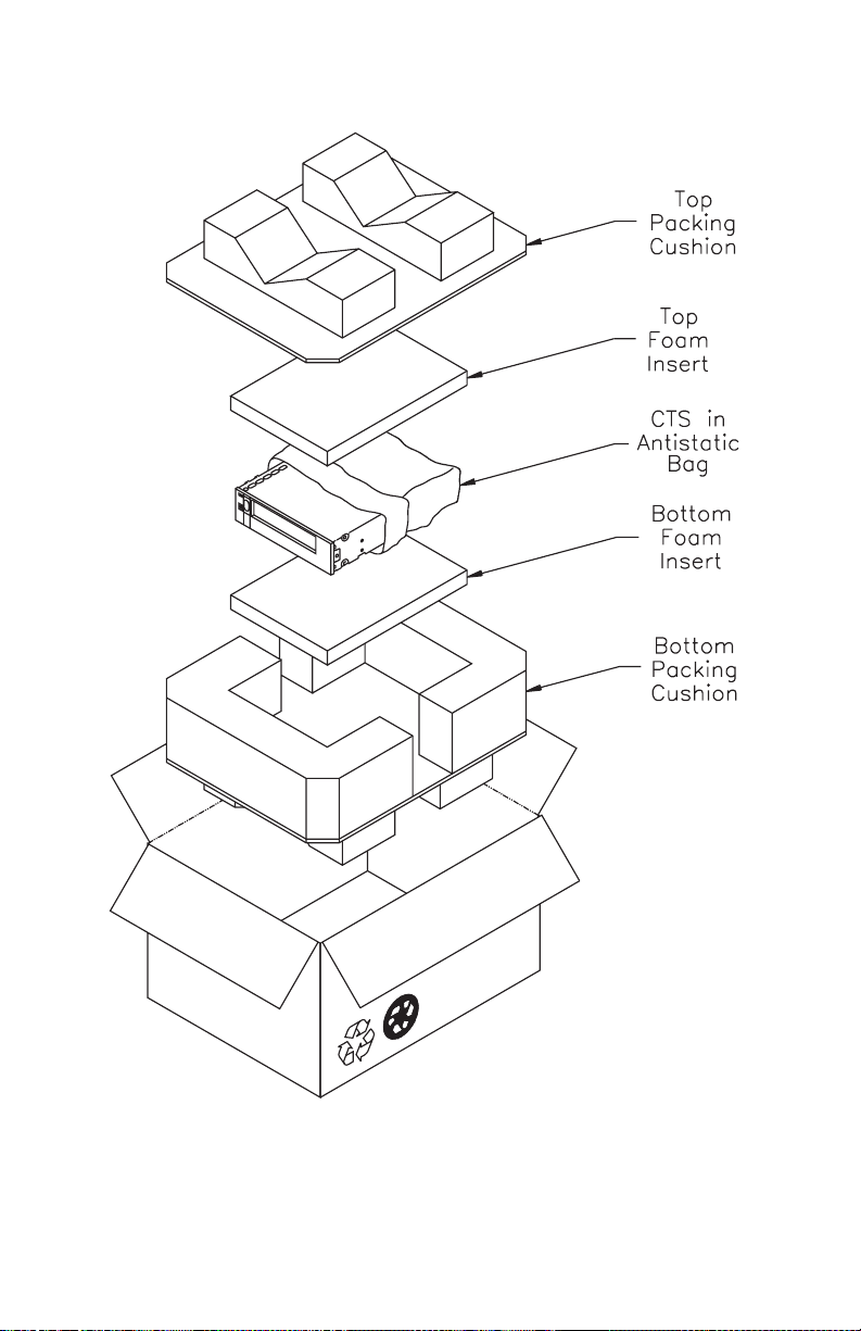
Figure 12 Single-pack carton an d packing materials
34
EXB-8205 and EXB-8505 (Standard and XL) 302967
Page 35
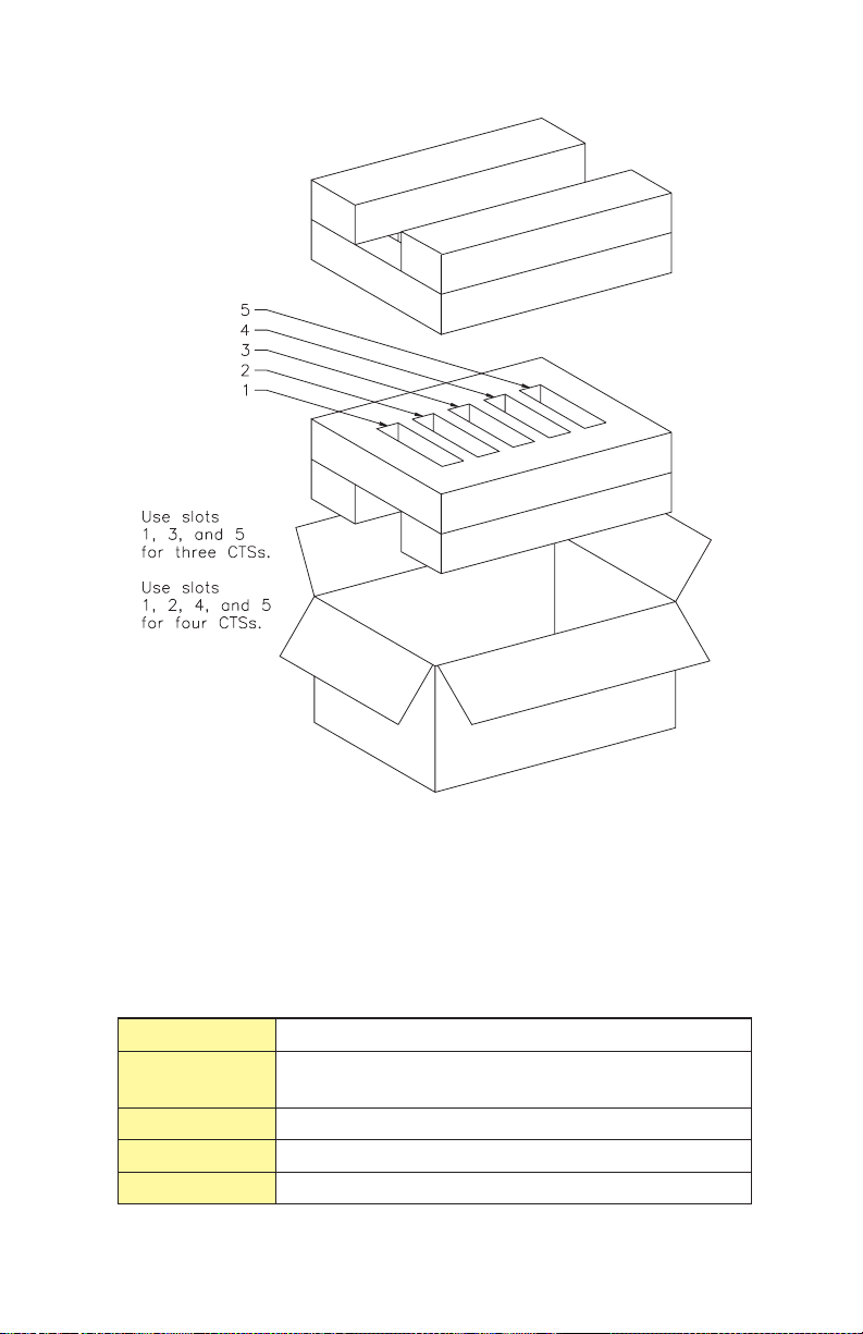
Figure 13 Multi-pack carton and packing materials
Environmental Requirements for Shipment
When shipping a tape drive, be sure to comply with the
environmental specifications shown in Table 5.
Table 5 Environmental specifications for shipping the tape drive
Temp. Range
Temp.
Variation
Rel. Humidity 10% to 90% non-condensing
Wet Bulb
Altitude -304.8 m to +12,192 m (-1,000 ft to +40,000 ft)
-40° Cto+60°C(-40°F to +140° F)
1° C per minute up to a maximum of 20° C per hour
(2° F per minute up to a maximum of 36° F per hour)
26° Cmax(79°F max)
May 1994 EXB-8205 and EXB-8505 (Standard and XL)
35
Page 36

Appendix A InstallationRequirements
This appendix lists the requirements for the following items:
SCSI cable
■
SCSI connector
■
Power cable
■
Power connector
It also provides guidelines for attaching the tape drive to a
frame and adding optional chassis grounding.
SCSI Cable
The SCSI cable for connecting the tape drive to the host is
not provided with the tape drive. You must provide a cable
that complies with the appropriate safety and regulatory
agency requirements. To comply with FCC, Canadian DOC,
and VDE limits, the tape drive requires shielded cables when
the cables are external to the mounting enclosure.
General Requirements
Use a 50-conductor flat cable or 25-signal twisted pair cable.
A minimum conductor size of 28 AWG is recommended to
minimize noise effects and ensure proper distribution of
terminator power.
36
Ideally, to match the cable terminators, the cable should
have a characteristic impedance of 122 ohms (differential) or
132 ohms (single-ended). However, since cables with this
high of a characteristic impedance are not generally
available, somewhat lower impedances are acceptable. A
characteristic impedance of 100 ohms ± 10% is
recommended for unshielded flat or twisted-pair ribbon
cable. A characteristic impedance greater than 90 ohms is
recommended for shielded cables.
Note: To minimize discontinuities and signal
reflections, ensure that cables used on the same
bus have the same impedances.
EXB-8205 and EXB-8505 (Standard and XL) 302967
Page 37

Cable Length Requirements for Differential
Configurations
For differential SCSI configurations, ensure that the sum of
all the SCSI cable lengths does not exceed 25.0 meters
(82.02 feet). A stub length of no more than 0.2 meters
(8 inches) is allowed off the mainline interconnection within
any connected equipment. The stub length within the tape
drive is less than 50 mm (1.97 inches).
Cable Length Requirements for Single-Ended
Configurations
For single-ended SCSI configurations, ensure that the sum of
all the SCSI cable lengths does not exceed 6.0 meters (19.68
feet). A stub length of no more than 0.1 meters (4 inches) is
allowed off the mainline interconnection within any
connected equipment. The stub length within the tape drive
is less than 50 mm (1.97 inches).
SCSI Connector
To connect the tape drive to the SCSI bus, use a 50-pin
female ribbon cable connector (AMP™ No. 1-746285-0 or
equivalent). The tape drive’s SCSI connector is located at the
rear of the tape drive. The connector is a 50-pin male ribbon
cable connector, consisting of two rows of 25 pins with
adjacent pins 2.54 mm (0.1 inch) apart. For information
about the specific SCSI connector pin assignments for
differential and single-ended tape drives, refer to the
EXB-8205 and EXB-8505 Product Specification.
May 1994 EXB-8205 and EXB-8505 (Standard and XL)
37
Page 38
Power Supply
The tape drive operates from standard +5 VDC and +12
VDC supply voltages; it does not use external AC power.
Safety agency certification requires that the supplied voltage
be from a Safety Extra-Low Voltage source (per IEC 950).
CAUTION
The tape drive does not provide any overvoltage or
overcurrent protection. For this reason, be sure that
the power is off before connecting the tape drive to
power.
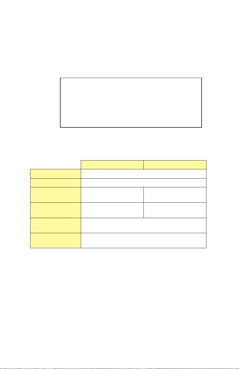
Table 6 lists the power specifications for the single-ended
and differential configurations of the tape drive.
Table 6 Power specifications for the tape drive
+5 Volts +12 Volts
Tolerance
Ripple and noise 125 mVpp max
Nominal
operating current
Maximum
current
Operating power
consumption
Idle power
consumption
1.7 Amps (single-ended)
2.1 Amps (differential)
2.8 Amps (single-ended)
3.2 Amps (differential)
14.5 watts (single-ended)
16.5 watts (differential)
13.0 watts (single-ended)
14.5 watts (differential)
±5%
0.5 Amps (single-ended)
0.5 Amps (differential)
1.6 Amps (single-ended)
1.6 Amps (differential)
Power Connector
The power connector used in the tape drive is compatible
with power connectors used for standard 5.25-inch devices.
To connect the tape drive to a power cable, use an AMP
1-480424-0 series or equivalent female connector. For
information about the specific power connector pin
assignments, refer to the EXB-8205 and EXB-8505 Product
Specification.
38
EXB-8205 and EXB-8505 (Standard and XL) 302967
Page 39

Attaching the tape drive to a Frame
The main housing of the tape drive includes three sets of
mounting holes (two sets on the sides and one set on the
bottom, as shown in Figures 14 and 15) to allow for a
number of mounting positions. These mounting holes
accommodate M3 5 6 mm screws. Refer to the EXB-8205
and EXB-8505 Product Specification for detailed information
about the spacing of these mounting holes.
When mounting the tape drive, follow these guidelines:
■
The mounting location must meet the environmental
requirements discussed in the Product Specification
for the tape drive. These requirements specify limits
for operating temperature, humidity, airflow,
particulate contamination, shock, and vibration.
■
The tape drive must be mounted solidly and
securely. To assure reliability, there must be no
distortion of the tape drive’s metal housing. Do not
install the tape drive in such a way that its frame is
unsupported. For example, do not hang the tape
drive by an edge.
■
You must use at least four mounting holes to secure
thetapedrive.Itishighlyrecommendedthatyou
use the four holes from only one set (“A,” “B,” or
“C,” as shown in Figures 14 and 15). Combinations
of mounting holes from different sets may lead to
distortion of the frame.
■
Objects such as screw heads, cables, or adjacent
devices must not press against the frame of the tape
drive.
■
The ventilation slots at the sides and top of the tape
drive must be free of obstruction so that adequate
airflow is provided.
■
There must be sufficient space to access and operate
the front panel controls.
May 1994 EXB-8205 and EXB-8505 (Standard and XL)
39
Page 40
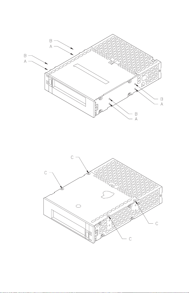
Figure 14 Mounting holes on the sides of the tape drive
Figure 15 Mounting holes on the bottom of the tape drive
40
EXB-8205 and EXB-8505 (Standard and XL) 302967
Page 41

Chassis Grounding (Optional)
If you needed additional chassis grounding, connect a
1
⁄4-inch female spade connector to the ground tab at the rear
of the tape drive. Or, connect an M3-0.5 6 mm self-tapping
screw to the grounding hole. The ground tab and grounding
hole are shown in Figure 7 on page 16.
Note: The power supply returns are connected to the
chassis, so you cannot isolate logic common
ground from chassis ground.
May 1994 EXB-8205 and EXB-8505 (Standard and XL)
41
Page 42
Appendix B Unload Button Options
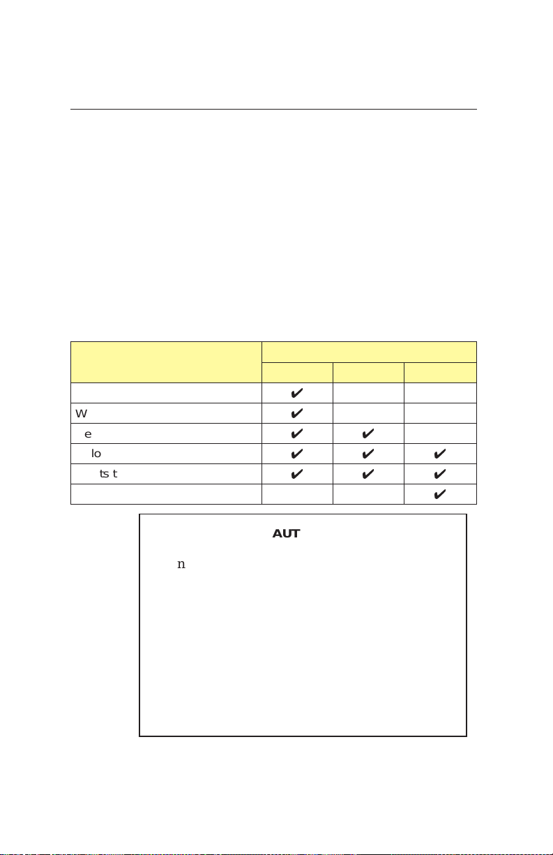
Depending on how your tape drive has been configured, the
unload button functions in one of three ways:
■
As a “normal” unload button (default)
■
Asa“fast”unloadbutton
■
As a “super fast” unload button
Table 7 summarizes the actions that occur with the three
unload button options. For further details about these three
options, refer to the EXB-8205 and EXB-8505 8mm SCSI
Reference.
Table 7 Summary of unload button options
tape drive
action
Completes current operation
Writes buffered data to tape
Rewinds the tape to PBOT
Unloads tape from tape path
Ejects the cartridge
Resets
When you use the “fast” or “super fast” unload
button while the tape drive is reading or writing
data,somedatamaybelost.
When you use the “super fast” unload button, the
tape is unloaded from the tape drive at its current
position without being rewound. If the unload
occurs when the tape is positioned over data, tape
damage and data loss can occur. Exabyte assumes
no liability for data loss occurring when the “super
fast” unload button option is used.
Unload button option
Normal Fast Super Fast
4
4
44
444
444
4
CAUTION
42
EXB-8205 and EXB-8505 (Standard and XL) 302967
Page 43

Note: With the “super fast” unload button, the tape
drive will unload the tape even if an error is
present during the unload procedure, unless the
error is a serious hardware error as follows:
■
Thetapedriveisunabletoremovethetape
from
the tape path and spool all of it into the cartridge.
In this case, the tape drive does not eject the
cartridge. This prevents the cartridge lid from
closing on the exposed tape.
■
The front load motor is not functioning. In this
case, the tape drive is physically incapable of
ejecting the cartridge.
May 1994 EXB-8205 and EXB-8505 (Standard and XL)
43
Page 44
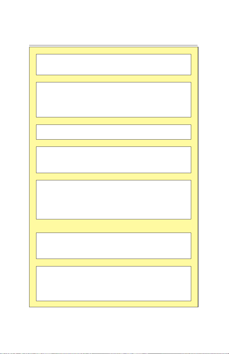
Appendix C TapeDrive Specifications
General
Interface SCSI-1 and SCSI-2, single-ended
or differential
Mean time between failure 160,000 hours
Physical Characteristics
Form factor 5.25-inch half-high
Size
4.1 cm high 14.6 cm wide
20.3 cm deep
(1.62 5.75 8.00 inches)
Weight 1.2 kilograms (2.6 pounds)
Environmental
Operating temperature
Operating Rel. humidity 20% to 80%, non-condensing
Maximum Sustained Data Transfer Rate
8200 format
8200c format
8500 format (EXB-8505)
8500caformat (EXB-8505)
Capacity on EXATAPE 112m Data Cartridge
8200 format
8200ca format
8500 format (EXB-8505 and
EXB-8505XL)
8500caformat (EXB-8505
and EXB-8505XL
Capacity on EXATAPE 160m XL Data Cartridge
(XL Tape Drives Only)
8200 format
8200ca format
8500 format (EXB-8505XL)
8500c format (EXB-8505XL)
Supply voltages
Maximum current 2.8 Amps (single), 3.2 Amps (differ)
Operating power
consumption
+5°Cto+40°C(+41°Fto+104°F)
262 KB/sec
a
500 KB/sec
500 KB/sec
1.0 MB/sec
Up to 2.5 GB
Up to 5.0 GB
Up to 5.0 GB
Up to 10.0 GB
)
Up to 3.5 GB
Up to 7.0 GB
Up to 7.0 GB
a
Up to 14.0 GB
Power
Standard +5 VDC and +12 VDC ±5%
at +5 VDC; 1.6 Amps at +12 VDC
14.5 watts (single-ended)
16.5 watts (differential)
a
Assuming a 2:1 compression ratio
44
EXB-8205 and EXB-8505 (Standard and XL) 302967
Page 45

Index
C
cable requirements
power cable 38
SCSI cable 36– 37
cartridges
see data cartridges
cartridge tape subsystem
see tape drive
chassis grounding 41
cleaning the tape drive
frequency 28
instructions 29 – 30
time-to-clean LED 28
condensation 8
CTS
see tape drive
D
data cartridges
160 XL 24
care of 30 – 31
loading 26
replacing 31
selecting 23
storing 30 – 31
unloading 27, 42
write-protect switch 25
differential SCSI
cable requirements 37
power requirements 38
termination 7, 12
drive
see tape drive
E
electrostatic discharge 8
EXATAPE8mm Data Cartridge 23– 24
G
grounding, chassis 16, 41
H
handling the tape drive 8
I
installation
attaching to a frame 39 – 40
cable requirements 36 – 38
connecting to power 16 – 17, 38
connecting to SCSI bus 11 – 13
in computer drive bay 13 – 17
setting the SCSI ID 9 – 10
J
jumpers for setting SCSI ID 9 – 10
L
LEDs
location 20
states indicated by 21 – 22
time-to-clean indication 28
load procedure 26
M
maintenance 28 – 30
mounting requirements 39
O
operating the tape drive 20 – 27, 42
P
packing the tape drive 32 – 35
power cable requirements 38
power specifications 38
power, connecting to 16 – 17, 38
preventive maintenance 28 – 30
R
R-packs 11 – 12
remote switch for setting SCSI ID 10
resistor terminators 11 – 12
S
SCSI bus
cable requirements 36 – 37
connecting the tape drive to 11 – 13
differential SCSI 37
single-ended SCSI 37
stub length 37
termination 7, 11 – 12
SCSI ID, setting 9 – 10
shipping the tape drive 32 – 35
single-ended SCSI
cable requirements 37
power requirements 38
termination 11
stub length 37
T
tape drive
cleaning 28 – 30
controls and indicators 20 – 21
installation 7 – 19, 38 – 40
loading a data cartridge 26
packing and shipping 32 – 35
specifications 44
unloading a data cartridge 27, 42
unpacking 8
terminators for SCSI bus 7, 11 – 12
May 1994 EXB-8205 and EXB-8505 (Standard and XL)
45
Page 46

U
unload button
location 20
options 27, 42
unload procedure 27, 42
unpacking instructions 8
W
write-protect switch 25
X
XL (eXtended-Length)
160m data cartridge 24
tape drives 5
46
EXB-8205 and EXB-8505 (Standard and XL) 302967
 Loading...