

Page 1

(;%0;538#)#(;%0;838#;PP#
7DSH#'ULYHV
VWDQGDUG#DQG#H;WHQGHG0/HQJWK#FRQILJXUDWLRQV
3URGXFW
6SHFLILFDWLRQ
510504-002
Page 2

Copyright
Disclaimer
Copyright 1994 by Exabyte Corporation. All rights reserved. This
item and the information contained herein are the property of
Exabyte Corporation. No part of this document may be reproduced,
transmitted, transcribed, stored in a retrieval system, or translated
into any language or computer language in any form or by any
means, electronic, mechanical, magnetic, optical, chemical, manual,
or otherwise, without the express written permission of Exabyte
Corporation, 1685 38th Street, Boulder, Colorado 80301.
Exabyte Corporation makes no representation or warranties with
respect to the contents of this document and specifically disclaims
any implied warranties of merchantability or fitness for any
particular purpose. Further, Exabyte Corporation reserves the right
to revise this publication without obligation to notify any person or
organization of such revision or changes.
Trademark Notices
Revision History
EXABYTE is a registered trademark and EXATAPE and
Compression Integrity Check are trademarks of Exabyte
Corporation. All other brand and product names are trademarks or
registered trademarks of their respective companies.
Revision Date
000 September 1992
001 March 1994 (preliminary draft for EXB-8205XL
and EXB-8505XL)
002 May 1994
Exabyte Corporation
1685 38th Street
Boulder, Colorado 80301
(303) 442-4333
510504-002
ii
EXB-8205 and EXB-8505
510504
(Standard and XL)
Page 3

Changes and Enhancements to This Manual
This revision (510504-002) of the EXB-8205 and EXB-8505 Product
Specification for Standard and eXtended Length (XL) Configurations
replaces the EXB-8205 8mm Cartridge Tape Subsystem Product
Specification (510703) and the EXB-8505 8mm Cartridge Tape Subsystem
Product Specification (510504). This manual includes the following
changes and enhancements:
The manual has been reorganized for easier reference. Chapters 1
through 3 include a general description of the tape drives, tape drive
functions, and related products; chapter 4 includes requirements for
installation, operation, and maintenance; chapter 5 includes SCSI
specifications; and chapters 6 and 7 include functional specifications and
compliance with safety and regulatory standards.
Information about the EXABYTE®EXB-8205 and EXB-8505 has been
consolidated into one manual. Information about the “eXtended Length”
(XL) configurations of these tape drives has also been included.
In the Related Products section, a description of the EXB-210 8mm
Library has been included. Information about extended length media,
including the Recognition System stripe on 160m XL EXATAPEä data
cartridges has been added. Exabyte cleaning cartridge information has
also been updated.
Detailed information about the relationship between physical track
structures and logical data formats has been added to the Physical
Format section.
May 1994
EXB-8205 and EXB-8505
(Standard and XL)
iii
Page 4

Product Warranty Caution
The EXB-8205, EXB-8205XL, EXB-8505, and EXB-8505XL 8mm
Cartridge Tape Subsystems are warranted to be free from defects in
materials, parts, and workmanship and will conform to the current
product specification upon delivery. For the specific details of your
warranty, refer to your sales contract or contact the company from
which the tape drive was purchased.
The warranty for the EXB-8205, EXB-8205XL, EXB-8505, and
EXB-8505XL shall not apply to failures caused by:
Physical abuse or use not consistent with the operating instructions or
product specifications provided by Exabyte’s personnel or agent for the
applicable equipment.
Use of any type of cleaning material other than an EXABYTE 8mm
Cleaning Cartridge (or an Exabyte-approved cleaning cartridge).
Modifications by other than Exabyte’s personnel or agent in any way
other than those approved by Exabyte, provided the warranty shall not
be voided by the repair or replacement of parts or the attachment of
items in the manner described in maintenance or installation instructions
provided by Exabyte.
Repair by other than Exabyte’s personnel or agent in a manner contrary
to the maintenance instructions provided by Exabyte.
Removal of the Exabyte serial number tag.
Physical abuse due to improper packaging of returns.
CAUTION
Returning the EXB-8205, EXB-8205XL, EXB-8505, or EXB-8505XL in
unauthorized packaging may damage the unit and void the warranty.
If you are returning the tape drive for repair, package it in its original
packaging (or in replacement packaging obtained from your vendor).
Refer to the packing instructions in this manual.
If problems with the tape drive occur, contact your maintenance
organization; do not void the product warranty by allowing
untrained or unauthorized personnel to attempt repairs.
iv
EXB-8205 and EXB-8505
510504
(Standard and XL)
Page 5

Contents
About This Manual xii
IntendedAudience.......................................xii
HowThisManualisOrganized................................xii
RelatedPublications ..................................... xiii
ConventionsUsedinThisSpecification.......................... xiv
1Features 1-1
Features ........................................... 1-2
Read/Write Compatibility with Other Tape Drives . . . . . . . . . . . . . . . 1-4
DataCompression .................................. 1-6
CustomEEPROMOptions ............................. 1-7
StorageCapacity ................................... 1-8
PhysicalDescription ..................................... 1-9
FrontPanelControlsandIndicators........................ 1-9
BackPanelComponents...............................1-11
InternalComponentsoftheTapeDrive......................1-13
SizeandWeight....................................1-17
RelatedProducts .......................................1-18
IntegrationwithOtherExabyteProducts.....................1-18
EXATAPEÔ DataCartridges ............................1-20
ExabyteCleaningCartridges ............................1-22
2Recording Format 2-1
Helical-ScanRecording ................................... 2-2
PhysicalFormat........................................ 2-3
PhysicalTrackStructure............................... 2-3
PhysicalBlocks .................................... 2-9
SearchFields .....................................2-10
ServoAreas ......................................2-10
Recording Parameters . . . . . . . . . . . . . . . . . . . . . . . . . . . . . . . . 2-11
LogicalFormat ........................................2-12
SupportedLogicalFormats .............................2-12
LogicalBlocks.....................................2-13
GapBytes .......................................2-15
GapBlocksandGapTracks.............................2-16
Filemarks .......................................2-17
Setmarks (EXB-8505 and EXB-8505XL only) . . . . . . . . . . . . . . . . . . . 2-18
EndofData(EOD)..................................2-18
TrackandBlockCounts ...................................2-19
May 1994 EXB-8205 and EXB-8505
(Standard and XL)
v
Page 6

3 Functional Description 3-1
WriteOperations ....................................... 3-2
DataFlowandDataCompression .........................3-2
StreamingandStart/StopModes.......................... 3-4
ThresholdsDuringaWriteOperation ....................... 3-5
Error Detection, Correction, and Recovery Procedures . . . . . . . . . . . . . 3-6
ReadOperations........................................ 3-7
ThresholdsDuringaReadOperation ....................... 3-8
4Requirements forUse 4-1
InstallationRequirements .................................. 4-2
RequirementsforSettingtheSCSIID........................ 4-2
RequirementsforMountingtheTapeDrive....................4-3
RequirementsforSCSIBusTermination......................4-6
RequirementsforConnectingaSCSICable .................... 4-7
Operation 4-11
Power-OnMode................................... 4-11
TapeDriveControls ................................ 4-11
DeviceStates..................................... 4-11
LoadingDataCartridges.............................. 4-14
UnloadingDataCartridges ............................ 4-15
ResettingtheTapeDrive.............................. 4-16
UsingSCSICommands............................... 4-17
PreventiveMaintenance .................................. 4-17
CleaningtheTapeDrive.............................. 4-17
DeterminingWhentheTapeDriveNeedsCleaning.............. 4-18
LoadingNewMicrocode.................................. 4-18
ShippingRequirements................................... 4-19
ShippingCartons .................................. 4-19
UnpackingandPackingInstructions....................... 4-20
5Interface Specifications 5-1
SCSIFeatures ......................................... 5-2
PhysicalPath ......................................... 5-2
SCSIMessages......................................... 5-3
SCSICommands........................................ 5-4
UsingSCSICommands.................................... 5-6
WritingData...................................... 5-6
ReadingData ..................................... 5-6
ErasingData...................................... 5-6
SearchingforData .................................. 5-7
CopyingMicrocode.................................. 5-7
InquiringAboutTapeDriveStatus......................... 5-7
PerformingDiagnosticTests............................. 5-8
SettingOperatingParameters............................ 5-8
vi
EXB-8205 and EXB-8505
(Standard and XL)
510504
Page 7

6 Functional Specifications 6-1
PerformanceSpecifications ................................. 6-2
WriteAccessTime .................................. 6-2
ReadAccessTime................................... 6-2
TapeSpeed ...................................... 6-3
RepositionTime.................................... 6-4
DrumRotationPeriod ................................ 6-5
TapeTensionReleaseandDrumMotionSuspension .............. 6-5
DataTransferRate .................................. 6-6
ReliabilitySpecifications................................... 6-7
ServiceLife ...................................... 6-7
Machine Reliability: Mean Time Between Failures (MTBF) . . . . . . . . . . . 6-7
DataIntegrity ..................................... 6-9
DataReliability ....................................6-10
PowerSpecifications.....................................6-12
Voltages ........................................6-12
PowerConnector...................................6-13
Grounding Hole and Ground Tab . . . . . . . . . . . . . . . . . . . . . . . . . 6-14
EnvironmentalSpecifications................................6-15
OperatingEnvironment...............................6-16
AirFlowRequirements ...............................6-17
ParticulateContaminationLimits .........................6-17
ShockSpecifications .................................6-18
Vibration Specifications . . . . . . . . . . . . . . . . . . . . . . . . . . . . . . . 6-19
AcousticNoise ....................................6-20
7Safety and Regulatory Agency Compliance 7-1
SafetyAgencyStandards .................................. 7-2
ElectrostaticDischarge(ESD)................................ 7-2
Electromagnetic Compatibility (EMC) . . . . . . . . . . . . . . . . . . . . . . . . . . . 7-3
RadiatedSusceptibility.................................... 7-3
Glossary G-1
Index I-1
May 1994 EXB-8205 and EXB-8505
(Standard and XL)
vii
Page 8

Figures
Features
Figure 1-1 Comparisonofthefourtapedrives...................... 1-3
Figure 1-2 Frontpanel.................................... 1-9
Figure 1-3 Labellocationandcontent .......................... 1-10
Figure 1-4 Backpanel(single-endedconfiguration).................. 1-11
Figure 1-5 Internal components (EXB-8505 shown) . . . . . . . . . . . . . . . . . . 1-13
Figure 1-6 Locationofthereadheadsandwriteheads ................ 1-14
Figure 1-7 External dimensions in inches (and millimeters) . . . . . . . . . . . . . 1-17
Figure 1-8 EXB-210 8mm Library . . . . . . . . . . . . . . . . . . . . . . . . . . . . . 1-18
Figure 1-9 Mini Tabletop CTSs with EXB-8505s installed . . . . . . . . . . . . . . . 1-19
Recording Format
Figure 2-1 Helical-scanrecording ............................. 2-2
Figure 2-2 Relationship of 8mm physical track structures to logical data formats . . 2-4
Figure 2-3 Physical track structure for 8500 and 8500c format . . . . . . . . . . . . . 2-5
Figure 2-4 Position of the tape drive’s heads relative to the tracks
(8500/8500c format) . . . . . . . . . . . . . . . . . . . . . . . . . . . . . . . 2-6
Figure 2-5 Physical track structure for 8200c track format . . . . . . . . . . . . . . . 2-7
Figure 2-6 Physical track structure for 8200 track format . . . . . . . . . . . . . . . . 2-7
Figure 2-7 Position of the tape drive’s heads relative to the tracks
(8200c format) . . . . . . . . . . . . . . . . . . . . . . . . . . . . . . . . . . 2-8
Figure 2-8 Physical block format for all logical formats
(8200c or 8500/8500c physical track structure shown) . . . . . . . . . . . 2-9
Figure 2-9 Logicalblockpacking(onephysicalblock) ................ 2-14
Figure 2-10 Gapbytes(onephysicalblock)....................... 2-15
Figure 2-11 One gap block and one gap track in two physical tracks . . . . . . . . 2-16
Functional Description
Figure 3-1 Dataflowduringawriteoperation...................... 3-2
Figure 3-2 Dataflowduringareadoperation ......................3-7
Requirements forUse
Figure 4-1 SCSI ID jumper block on the back panel (single-ended configuration) . . 4-2
Figure 4-2 Mountingholesonthesides.......................... 4-4
Figure 4-3 Mountingholesonthebottom......................... 4-4
Figure 4-4 Mounting hole dimensions in inches (and millimeters) . . . . . . . . . . 4-5
Figure 4-5 SCSIconnectorlocationonthebackpanel.................. 4-8
Figure 4-6 LEDs on the faceplate of the EXB-8505 and EXB-8505XL . . . . . . . . . 4-12
Figure 4-7 LEDs on the faceplate of the EXB-8205 and EXB-8205XL . . . . . . . . . 4-12
viii
EXB-8205 and EXB-8505
(Standard and XL)
510504
Page 9

Functional Specifications
Figure 6-1 Powerconnectorlocationonthebackpanel.................6-13
Figure 6-2 Chassisgroundlocationonbackpanel....................6-14
Figure 6-3 Temperatureandhumidityrangesforoperation..............6-16
Figure 6-4 Particulatecontaminationspecificationvs.typicaloffice .........6-18
May 1994 EXB-8205 and EXB-8505
(Standard and XL)
ix
Page 10

Tables
Features
Table 1-1 Comparisonoftapedrivefeatures....................... 1-4
Table 1-2 Read/write compatibility of Exabyte 8mm tape drives . . . . . . . . . . . 1-5
Table 1-3 Dataformatfeatures...............................1-5
Table 1-4 Approximate capacities of EXATAPE data cartridges . . . . . . . . . . . . 1-8
Table 1-5 EXATAPE media compatibility with 8mm tape drives . . . . . . . . . . 1-21
Recording Format
Table 2-1 Recording parameters . . . . . . . . . . . . . . . . . . . . . . . . . . . . . 2-11
Table 2-2 Typeandsizeoffilemarksforeachformat ................. 2-17
Table 2-3 Track and physical block counts for 8200 and 8200c formats . . . . . . . 2-20
Table 2-4 Track and physical block counts for 8500 and 8500c formats . . . . . . . 2-20
Requirements forUse
Table 4-1 Connector pin assignments for differential tape drives . . . . . . . . . . . 4-9
Table 4-2 Connector pin assignments for single-ended tape drives . . . . . . . . . 4-10
Table 4-3 LEDstatesduringoperation ......................... 4-13
Table 4-4 Single pack and multi-pack shipping dimensions and weights . . . . . 4-19
Interface Specifications
Table 5-1 SCSImessages .................................. 5-3
Table 5-2 SCSI-2commandset............................... 5-4
Functional Specifications
Table 6-1 Nominaltapespeed ............................... 6-3
Table 6-2 File-searchtapespeeds..............................6-3
Table 6-3 Typicalrewindtimes............................... 6-4
Table 6-4 Drumrotationperiods.............................. 6-5
Table 6-5 Datatransferrates ................................ 6-6
Table 6-6 Powerspecificationsforstandardvoltages................. 6-12
Table 6-7 Powerconnectorpinassignments ...................... 6-13
Table 6-8 Environmentalspecifications......................... 6-15
Table 6-9 Temperatureandhumidityspecifications.................. 6-16
Table 6-10 Particlecontaminationlimits ........................ 6-17
Table 6-11 Shockspecifications.............................. 6-18
Table 6-12 Vibration specifications . . . . . . . . . . . . . . . . . . . . . . . . . . . . 6-19
Table 6-13 Acousticnoiselimits ............................. 6-20
x
EXB-8205 and EXB-8505
(Standard and XL)
510504
Page 11

About This Manual
This product specification describes the functional, performance, and
environmental specifications for the following EXABYTE
Cartridge Tape Subsystems (tape drives):
EXB-8205
EXB-8205XL (extended length)
EXB-8505
EXB-8505XL (extended length)
Intended Audience
This manual is for engineering, purchasing, or marketing personnel
who want to evaluate the EXB-8205, EXB-8205XL, EXB-8505, and
EXB-8505XL to determine the feasibility of integrating them into
product lines.
How This Manual isOrganized
This manual contains the following chapters:
®
8mm
Chapter 1 describes the features of the tape drives, including
compatibility with other Exabyte 8mm Cartridge Tape
Subsystems, data compression, tape capacity, and custom
EEPROM options. This chapter also describes the physical
features of the tape drives, including mechanical and electrical
components.
Chapter 2 describes the physical and logical recording formats
used by the tape drives, including the implementation of
helical-scan recording technology.
Chapter 3 describes the functional features of the tape drives,
including how they perform read and write operations.
Chapter 4 lists the requirements for installing, operating,
maintaining, and shipping the tape drives.
Chapter 5 describes how the tape drives implement the Small
Computer System Interface (SCSI), including an overview of SCSI
messages and commands.
Chapter 6 lists performance, reliability, power, and environmental
specifications.
May 1994 EXB-8205 and EXB-8505
(Standard and XL)
xi
Page 12

Chapter 7 describes compliance with regulatory and safety
agency standards, including electromagnetic susceptibility (EMI),
susceptibility to electrostatic discharge (ESD), and radiated
susceptibility.
This product specification contains a glossary and an index.
Related Publications
The following publications list additional, related information.
EXB-8205 and EXB-8505 8mm Cartridge Tape Subsystems
For information about installing, operating, and maintaining the
EXB-8205, EXB-8205XL, EXB-8505, and EXB-8505XL, and for
information about implementing SCSI commands, refer to the
following publications:
EXB-8205 and EXB-8505 8mm Cartridge Tape Subsystems SCSI
Reference for Standard and eXtended Length Configurations,
510503
EXB-8205 and EXB-8505 8mm Cartridge Tape Subsystems
Integration and Optimization for Standard and eXtended Length
Configurations, 510505
EXB-8205 and EXB-8505 8mm Cartridge Tape Subsystems
Installation and Operation for Standard and eXtended Length
Configurations, 302967
Libraries and Enclosures
For information about libraries and enclosures currently available for
the EXB-8205, EXB-8205XL, EXB-8505, and EXB-8505XL, refer to the
following publications:
EXB-210 8mm Library Product Specification, 510807
Mini Tabletop 8mm Cartridge Tape Subsystem Product
Specification, 520154
xii
EXB-8205 and EXB-8505
(Standard and XL)
510504
Page 13

Standards
For information about the standards used for the tape drives, refer to
the following publications:
ANSI Small Computer System Interface (SCSI), X3.131 - 1989
ANSI Small Computer System Interface-2 (SCSI-2), X3.131 -1994
ANSI/ISO/IEC 11319-1992 and ECMA-145, Information
Technology —8mm Wide Magnetic Tape Cartridge for
Information Interchange, July 1992
ISO/IEC 12246 and ECMA-169, Information Technology—8mm
Wide Magnetic Tape Cartridge Dual Azimuth Format for
Information Interchange, Helical Scan Recording
Conventions Used in ThisSpecification
This specification uses special conventions to highlight notes, important
information, and cautions. These conventions are explained below.
Note: ReadNotesforhintsorsuggestionsabout the topic or procedure
being discussed.
Important Read
#
topic or procedure being discussed.
Read the information in
damaging the equipment.
Important
CAUTION
text to learn crucial information about the
CAUTION
boxes to learn ways to avoid
May 1994
EXB-8205 and EXB-8505
(Standard and XL)
xiii
Page 14

Notes:
xiv
EXB-8205 and EXB-8505
(Standard and XL)
510504
Page 15

Features
This chapter provides an overview of the EXB-8205, EXB-8205XL,
EXB-8505, and EXB-8505XL, including:
Features
Physical description
Related products
1
May 1994 EXB-8205and EXB-8505 1-1
(Standard and XL)
Page 16

1 Features
Features
The EXB-8205, EXB-8205XL, EXB-8505, and EXB-8505XL are enhanced
8mm digital helical-scan cartridge tape subsystems (tape drives). The
tape drives are packaged in the industry standard 5.25-inch half-high
form factor, which allows for ease of integration across a multitude of
platforms.
Featuring an integral Small Computer System Interface (SCSI)
controller (either single-ended or differential configuration), these
tape drives are the easily integrated solution to your journaling,
archiving, data interchange, software distribution, imaging, data
acquisition, and backup/restore needs.
Note: This specification applies to the EXB-8205, EXB-8205XL,
EXB-8505, and EXB-8505XL. However, most of the
illustrations in this manual show the EXB-8505.
In their compressed modes, the EXB-8205 can store up to 5 GBytes
and the EXB-8505 can store up to 10 GBytes on a single 112m data
cartridge, assuming an average compression ratio of 2:1.
The eXtended-Length (XL) configurations of these tape drives
provide additional capacity by supporting EXATAPE
Data Cartridges. Assuming an average compression ratio of 2:1, the
EXB-8505XL can store up to 14 GBytes of data on a single 160m XL
data cartridge. Assuming the same compression ratio, the
EXB-8205XL can store up to 7 GBytes on a single data cartridge.
For more information on EXATAPE data cartridge capacity, see
page 1-8. For more information on EXATAPE data cartridges, see
page 1-20.
Important EXATAPE 160m XL 8mm Data Cartridges are only
#
supported by the extended length tape drives (EXB-8205XL and
EXB-8505XL). The standard tape drives (EXB-8205 and
EXB-8505) cannot write on or read from 160m XL data cartridges
and will automatically eject them.
160m XL 8mm
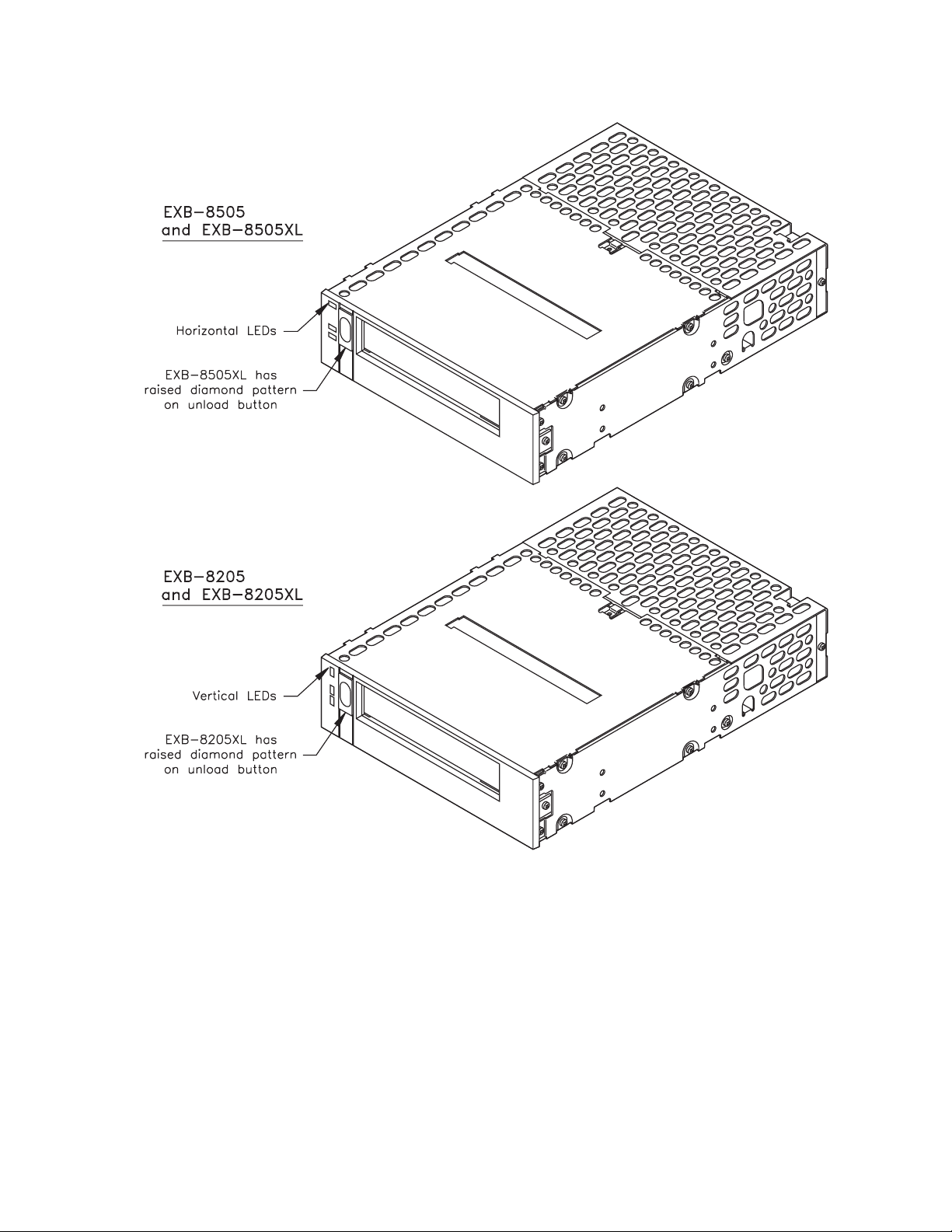
AsshowninFigure1-1,thefourtapedrivemodelslookidentical,
except for minor differences in the LEDs and the unload button.
1-2 EXB-8205 and EXB-8505 510504
(Standard and XL)
Page 17
1 Features
Figure 1-1 Comparison of the four tape drives
The EXB-8205XL and EXB-8505XL are fully compatible with the
EXB-8205 and EXB-8505; each extended length tape drive supports all
of the tape sizes and data formats supported by the corresponding
standard tape drive. You can distinguish an extended length tape
drive from a standard tape drive by checking the unload button. The
extended length tape drives have a raised diamond pattern on the
unload button.
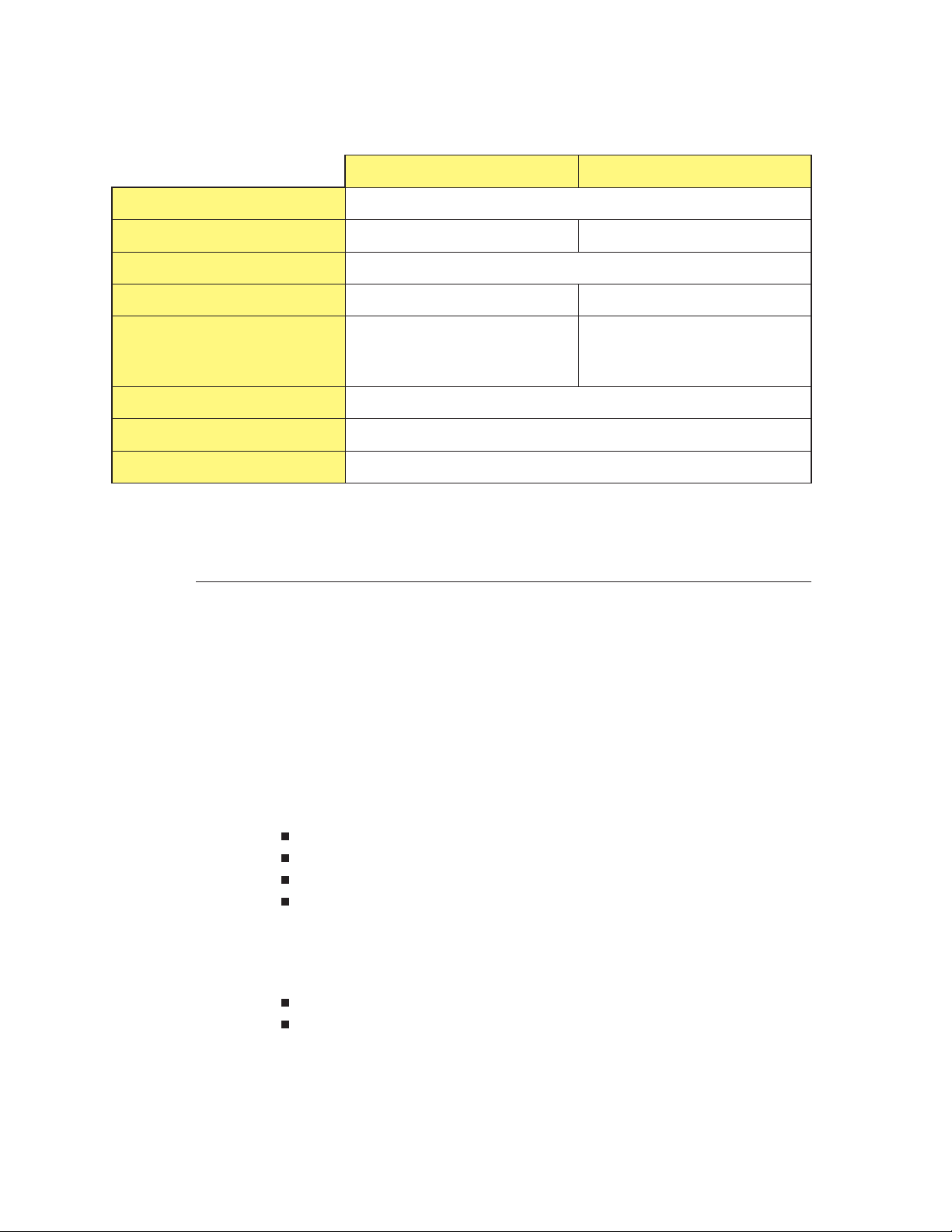
Table 1-1 compares the features of the tape drives.
May 1994 EXB-8205and EXB-8505 1-3
(Standard and XL)
Page 18
1 Features
Table 1-1 Comparison of tape drive features
EXB-8505 and EXB-8505XL EXB-8205 and EXB-8205XL
Form factor
Data formats supported
Buffer size 1.0 MByte
Data transfer rate* 1.0 MByte per second 500 KBytes per second
Search speed
Synchronous data transfer
Time-to-clean LED indication yes
Compression
*These figures represent the maximum sustained data transfer rate, assuming a 2:1 data compression ratio.
8200, 8200c, 8500, 8500c 8200, 8200c
75X normal (8500c, 8500, and
8200c formats)
10X normal (8200 format)
Half-high 5.25 inches
75X normal (8200c format)
10X normal (8200 format)
yes
yes
Read/Write Compatibility with OtherTape Drives
The EXB-8205, EXB-8205XL, EXB-8505, and EXB-8505XL can read data
cartridges written by other Exabyte 8mm tape drives, including the
EXB-8200, the EXB-8200SX, the EXB-8500, and the EXB-8500c. They
can also write on data cartridges that are intended for use with these
other tape drives.
Supported Formats
The EXB-8505 and EXB-8505XL read and write data in four logical
formats:
8200
8200c (compressed)
8500
8500c (compressed)
The EXB-8205 and EXB-8205XL read and write data in two logical
formats:
8200
8200c (compressed)
Table 1-2 shows the read and write compatibility of the four logical
data formats with the tape drives. Table 1-3 compares these data
formats.
1-4 EXB-8205 and EXB-8505 510504
(Standard and XL)
Page 19
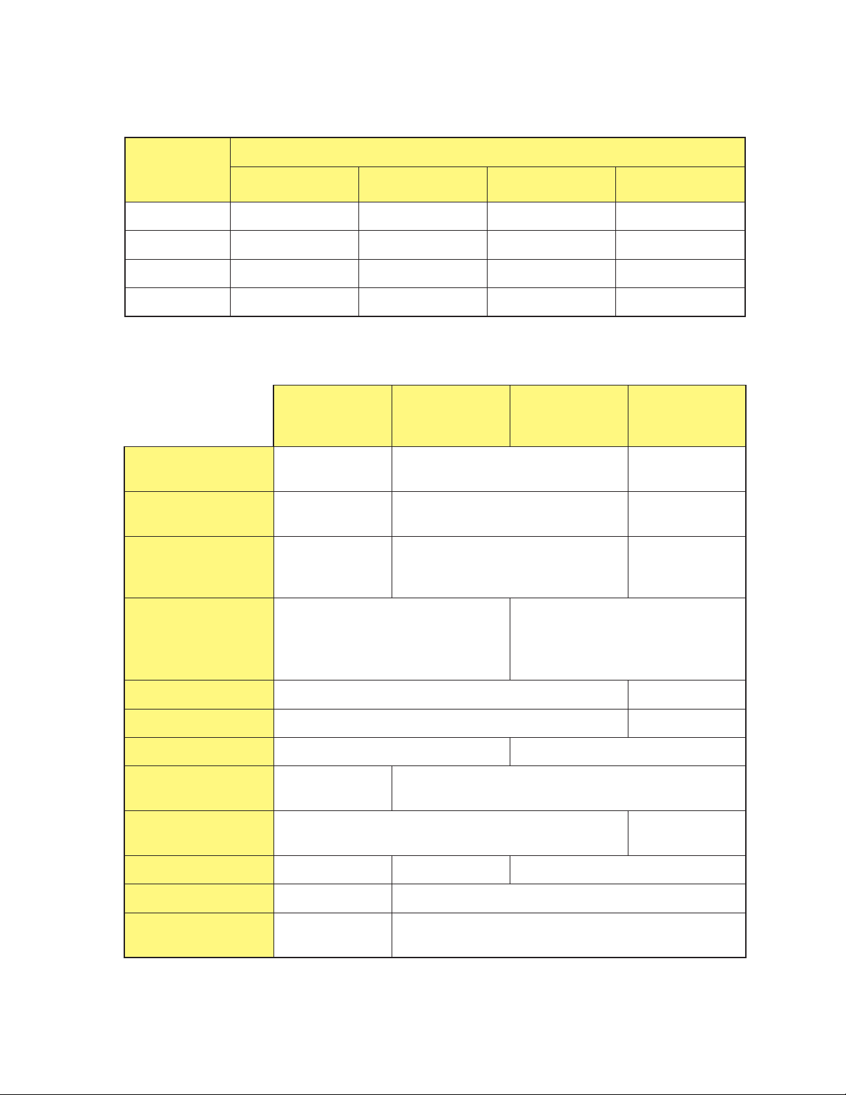
Table 1-2 Read/write compatibility of Exabyte 8mm tape drives
1 Features
Atape
written in
this format...
8200
8200c
8500
8500c
EXB-8205 EXB-8205 XL EXB-8505 EXB-8505 XL
4444
4444
Table 1-3 Data format features
Maximum sustained
data transfer rate
Maximum capacity on
112m tape
Maximum capacity
on 160m XL tape (XL
configurations only)
8200
format
262
KBytes/sec
2.5
GBytes
3.5
GBytes
Can be read and written by an ...
44
44
8200c
format*
KBytes/sec
GBytes
GBytes
8500 format
(EXB-8505 and
EXB-8505XL)
500
5.0
7.0
8500c format*
(EXB-8505 and
EXB-8505XL)
1.0
MByte/sec
10.0
GBytes
14.0
GBytes
Track
structure
Supports partitions
Supports setmarks
Long filemarks
Short filemarks
Setmarks
EOD mark
Search fields no yes
Logical
block packing
*Assumes a data compression ratio of 2:1.
Helical scan: One write head writes
a single data track
witha–10°azimuth.
no yes
no yes
270 tracks (2,160 KBytes) 6 tracks (48 KBytes)
23 tracks
(184 KBytes)
no
no yes–849 tracks yes–602 tracks
no yes
one 1-KByte physical block
Helical scan: Two write heads write
two overlapping data tracks.
Track 1 = +20° azimuth.
Track 2 = –10° azimuth.
yes–6 tracks
(48 KBytes)
May 1994 EXB-8205and EXB-8505 1-5
(Standard and XL)
Page 20

1 Features
Determining the Tape Format
When writing data to tape, the tape drive does one of the following:
If the tape is positioned at the logical beginning of tape (LBOT),
the tape drive writes data in the default format or whatever
format you select with the SCSI MODE SELECT (15h) command.
(The tape drive allows only one format on any one tape.)
If the tape is positioned at any other valid position for writing
data, the tape drive writes data in the same format as the data
already on the tape.
When reading a data cartridge, the tape drive automatically
determines the tape’s format.
Data Compression
When the tape drive compresses data, it uses the established
Improved Data Recording Capability (IDRC) algorithm. Licensed
from IBM, this algorithm is the de facto standard in mainframe
environments. The tape drives also use the Exabyte Compression
Integrity Check™ feature to ensure that data is accurately compressed
and decompressed into the original form sent by the initiator.
The compression algorithm is completely contained in an Exabyte
proprietary integrated circuit. The tape drive invokes the compression
algorithm intelligently, constantly monitoring the compression ratio
to determine whether compressing the data will actually decrease the
size of the data set. The tape drive sends compressed data to tape only
when it benefits the user’s storage capacity and throughput.
Although the actual data compression ratio depends on the type of
data, the EXB-8205, EXB-8205XL, EXB-8505, and EXB-8505XL achieve
an average compression ratio of 2:1.
For detailed information about how the tape drives compress data,
see Chapter 3.
1-6 EXB-8205 and EXB-8505 510504
(Standard and XL)
Page 21

Custom EEPROM Options
When the tape drive is manufactured, a number of operating features
and default values are programmed in the electronically erasable
programmable read-only memory (EEPROM). These operating
features and default values, called EEPROM options, include such
items as MODE SELECT power-on default values, command set
options, hardware operation options, and SCSI configuration options.
When you order a tape drive, you can contact an Exabyte account
manager to select which, if any, EEPROM settings you want to change
from their standard settings. Using this information, Exabyte can
create a customized EEPROM image that meets your integration and
application development needs. Once your designated EEPROM
structure is released, each tape drive you purchase will be
factory-configured to your specifications.
1 Features
Note: You can use the CTS Monitor program to change some of the
tape drive’s EEPROM option settings. For more information
about these options, refer to the documentation for the CTS
Monitor program.
May 1994 EXB-8205and EXB-8505 1-7
(Standard and XL)
Page 22

1 Features
Storage Capacity
Table 1-4 lists the approximate storage capacities of 8mm data
cartridges written in the four logical formats. For more information
on EXATAPE 8mm data cartridges, see page 1-20.
Table 1-4 Approximate capacities of EXATAPE data cartridges
Length of
Approximate Capacity to LEOTain MBytes
EXATAPE
8500c
compressed
format
b
(EXB-8505 and
8500 format
(EXB-8505 and
EXB-8505XL)
8200c
compressed
format
b
8200 format
EXB-8505XL)
15m 1,176 588 588 294
54m
4,697 2,348 2,348 1,174
112m 9,888 4,944 4,698 2,349
160m XL
a
Logical end of tape.
b
These columns assume an average compression ratio of 2:1 (on average, each compressed 1,024-byte
physical block represents 2,048 bytes of user data).
c
EXATAPE 160m XL extended length media is compatible with the EXB-8205XL and EXB-8505XL only.
c
14,000 7,000 7,000 3,500
1-8 EXB-8205 and EXB-8505 510504
(Standard and XL)
Page 23
Physical Description
This section describes the physical features of the tape drive,
including the following:
External features
Size and weight
Internal components
Front Panel Controls and Indicators
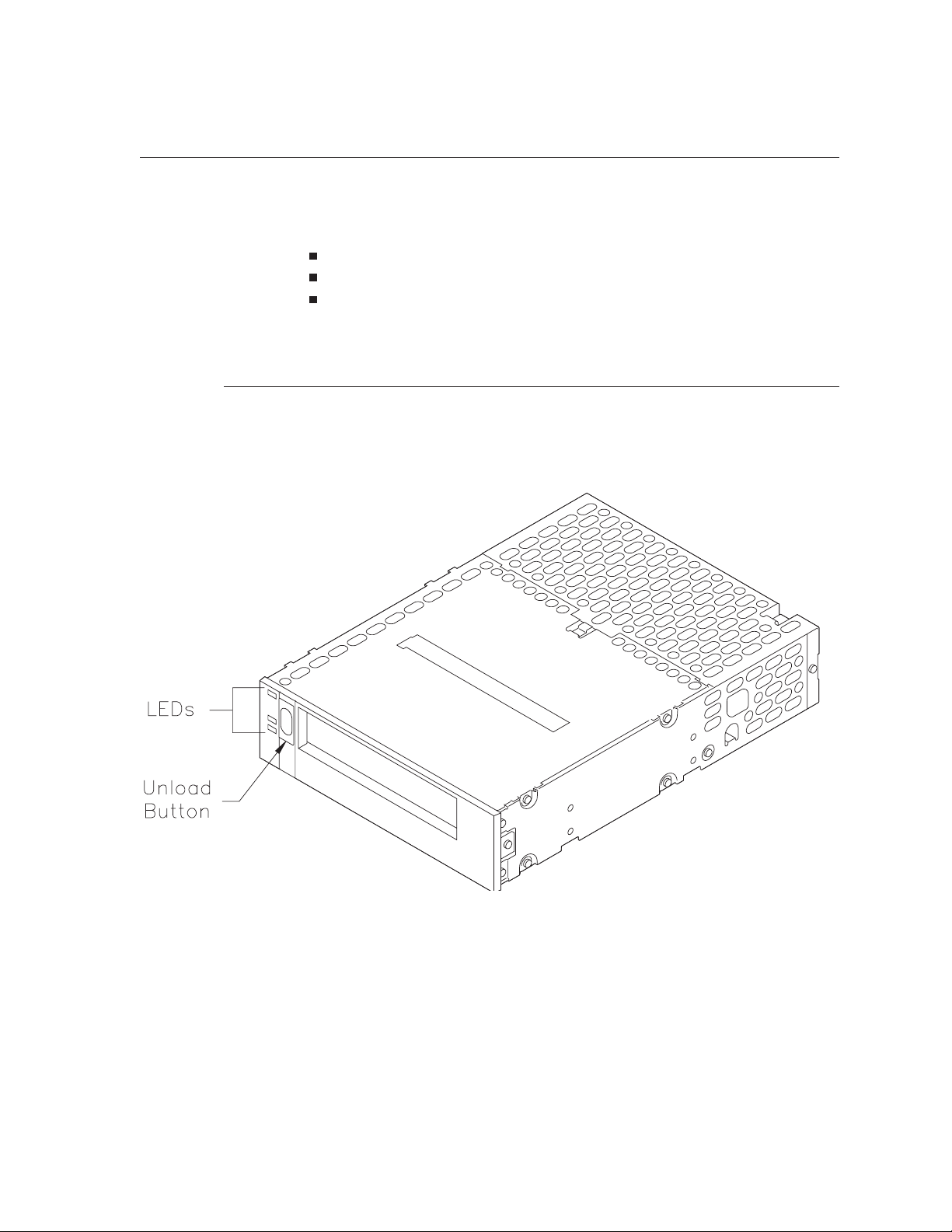
Figure 1-2 shows the controls and indicators on the front panel of the
tape drive.
1 Features
Figure 1-2 Front panel
Door and Bezel
Standard colors for the door and bezel include black, pearl white,
pebble gray, platinum, and gray. Exabyte can provide custom colors
at an additional cost. (Contact your account manager for more
information.)
May 1994 EXB-8205and EXB-8505 1-9
(Standard and XL)
Page 24
1 Features
Unload Button
The unload button is the only operator control on the tape drive.
Pushing this button starts the unload procedure. On the EXB-8205
and EXB-8505, the unload button is smooth and has an oval-shaped
indentation. On the EXB-8205XL and EXB-8505XL, the unload button
has a diamond texture.
See Chapter 4 for more information about loading and unloading
cartridges.
LEDs
The tape drive contains three LEDs on the front panel. Various
combinations of these LEDs (either on, off, or flashing) indicate the
status of the tape drive operations. See Chapter 4 for more
information about the LED functions.
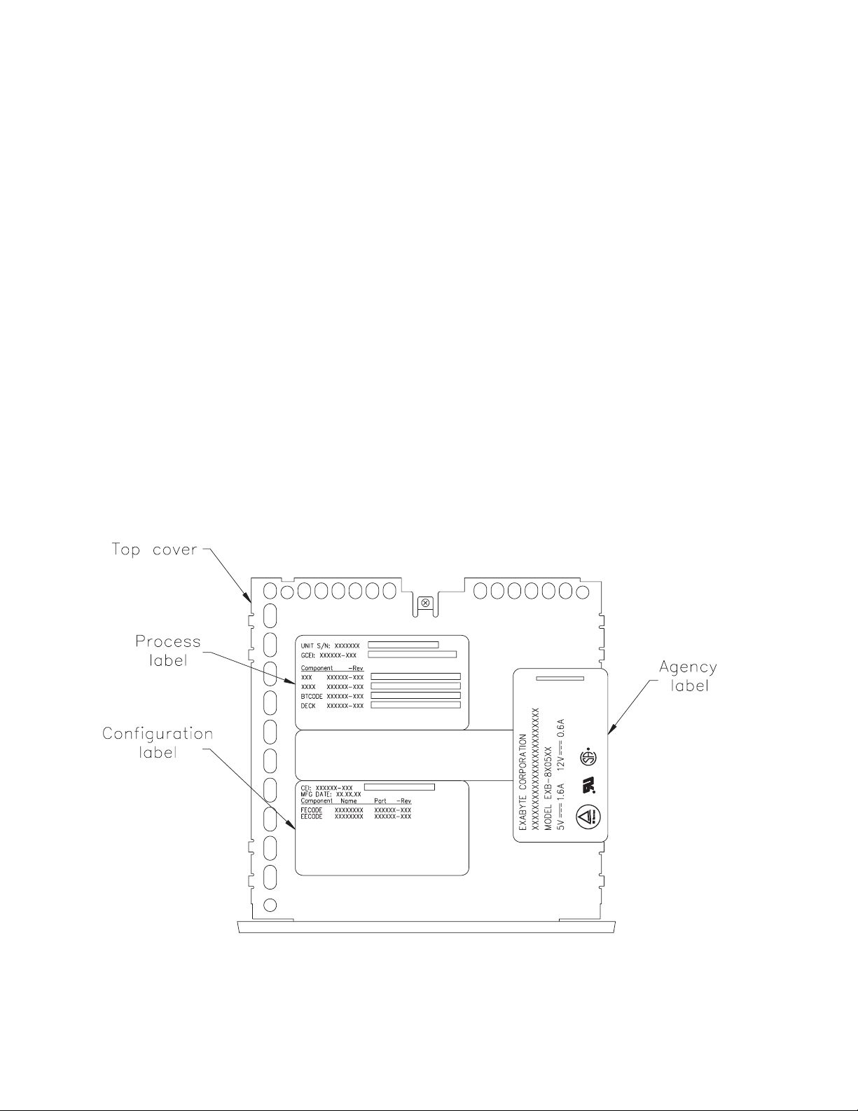
Labels
All Exabyte products are required to include standard process,
configuration, and agency labels. Figure 1-3 shows the location and
content of these labels on the top cover of the tape drive.
Figure 1-3 Label location and content
1-10 EXB-8205 and EXB-8505 510504
(Standard and XL)
Page 25
Back Panel Components
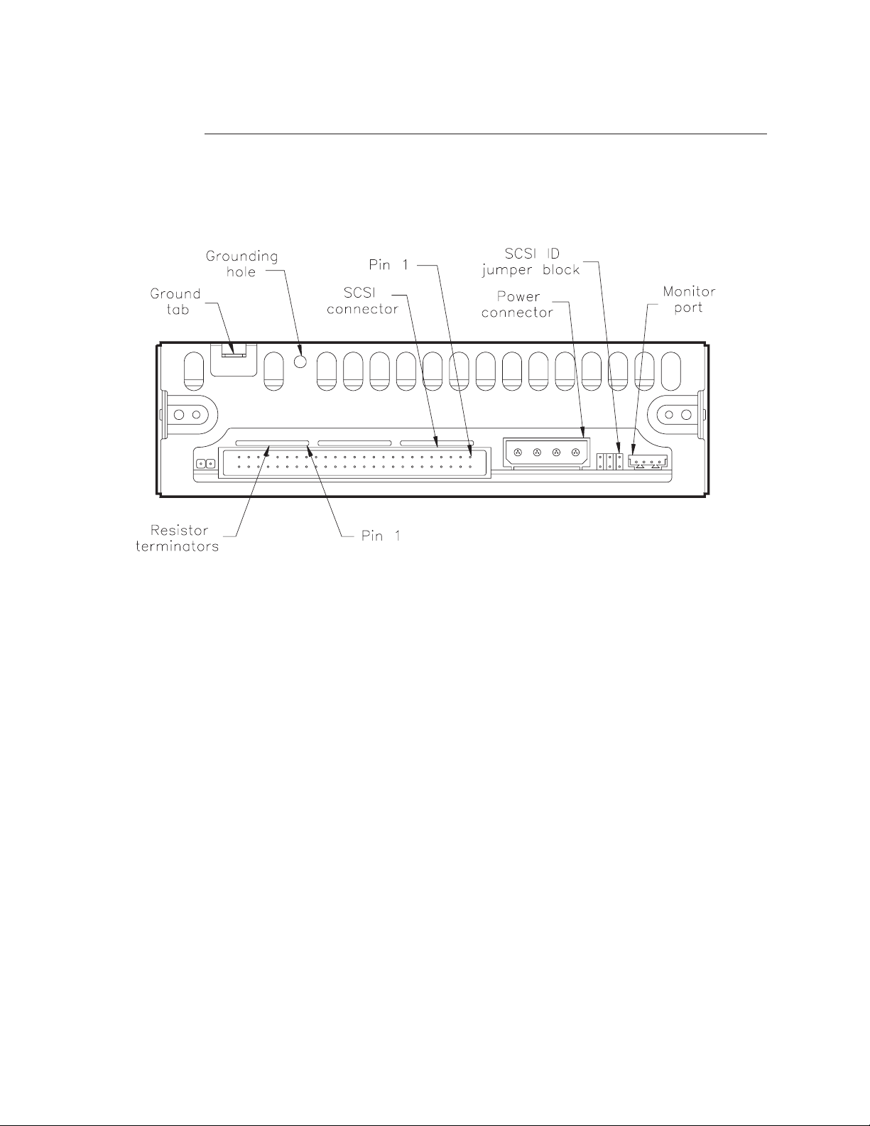
Figure 1-4 shows the back panel of a single-ended tape drive. The
differential tape drives look similar except that there are no SCSI
terminator R-packs (resistor terminators).
1 Features
Figure 1-4 Back panel (single-ended configuration)
Ground Tab and Grounding Hole
The tape drive includes a ground tab and grounding hole to use if
you want additional chassis grounding. See Chapter 6 for more
information.
SCSI Connector
The 50-pin SCSI connector on the tape drive allows you to connect the
tape drive to the SCSI bus. Pin 1 is the first pin on the right side of the
top row.
See Chapter 5 for more information about connecting the tape drive to
the SCSI bus.
Power Connector
The 4-pin power connector on the tape drive is compatible with the
power connector used for standard 5.25-inch half-high devices. See
Chapter 6 for more information.
May 1994 EXB-8205and EXB-8505 1-11
(Standard and XL)
Page 26

1 Features
SCSI ID Jumper Block
The SCSI ID jumper block on the tape drive enables you to set the
SCSI ID either by using a remote switch or by installing jumpers. See
Chapter 4 for more information about setting the SCSI ID.
Monitor Port
Using the Monitor port, you can change some of the tape drive’s
configuration options, download code updates, and perform
diagnostic procedures on the tape drive.
To use the Monitor port, you will need the Exabyte CTS Monitor
program and an IBM AT
port.
If your tape drive has a 3-pin Monitor port, you will need the
following cables and connectors:
A 3-pin to RJ-11 modular phone plug cable (Exabyte part number
303772)
®
, XT™, or compatible system with a serial
An RJ-11 to 9-pin level shifter (Exabyte part number 301001)
A 9-pin to 25-pin adapter cable (if your computer system has a
25-pin serial port)
If your tape drive has a 4-pin Monitor port, you will need the
following cables and connectors:
A 4-pin to 25-pin connector cable (Exabyte part number 727005)
A 25-pin to 9-pin adapter cable (if your computer system has a
9-pin serial port)
Resistor Terminators (single-ended configuration only)
The single-ended configuration of the EXB-8205 or EXB-8505 includes
three single inline package (SIP) resistor terminators (R-packs) that
you can use if the tape drive is the terminating device for the SCSI
bus. You can remove these terminators if the tape drive does not
terminate the bus or if you want to use external terminators. The first
pinisontherightendoftheterminator.
Note: The differential configuration of the tape drive does not
include internal terminators and must be terminated
externally.
1-12 EXB-8205 and EXB-8505 510504
(Standard and XL)
Page 27
Internal Components of theTape Drive
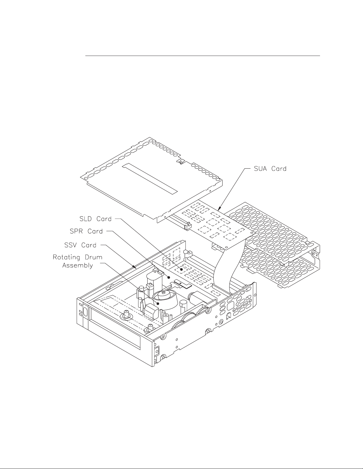
This section describes the internal components of the tape drive,
including the tape transport mechanism, the rotating drum assembly,
and each of the four main cards.
Figure 1-5 shows the internal components of the EXB-8505 and
EXB-8505XL. The EXB-8205 and EXB-8205XL have a VUA card
instead of the SUA card shown below.
1 Features
Figure 1-5 Internal components (EXB-8505 shown)
May 1994 EXB-8205and EXB-8505 1-13
(Standard and XL)
Page 28
1 Features
Tape Transport Mechanism
The 8mm tape transport mechanism is manufactured by Sony to
Exabyte specifications. It is compatible with 8mm data cartridges that
meet the ECMA-145 standard.
Rotating Drum Assembly
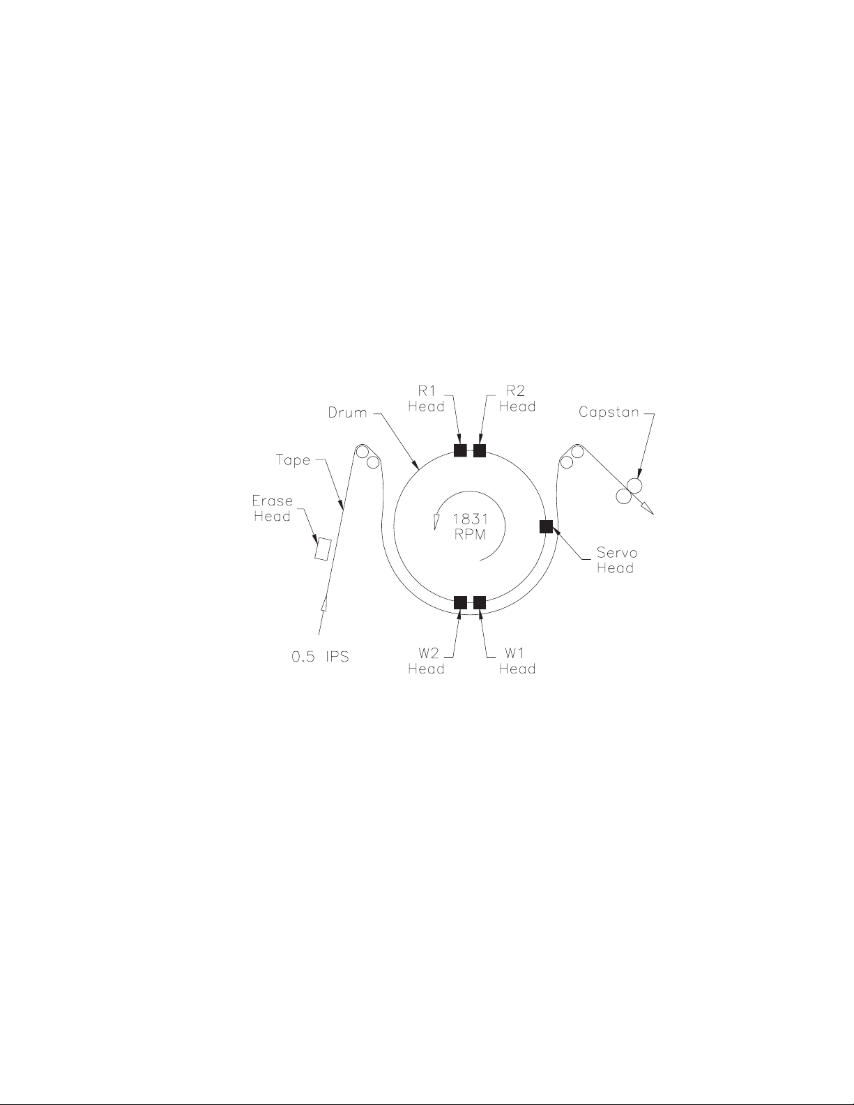
The rotating drum assembly in the EXB-8205 and EXB-8205XL has
one write head, one read head, and one servo head. The rotating
drum assembly in the EXB-8505 and EXB-8505XL has five heads: two
write h eads (W1, W2), two read heads (R1, R2), and one servo head.
Figure 1-6 shows the location of the heads on the EXB-8505 and
EXB-8505XL drum assembly.
Figure 1-6 Location of the read heads and write heads (EXB-8505)
In the EXB-8505 and EXB-8505XL, the write and read heads can write
and read two tracks of information simultaneously.
The servo head is used for reading servo data, which enables the tape
drive to control linear tape velocity to ensure accurate positioning of
the read heads over the tape.
1-14 EXB-8205 and EXB-8505 510504
(Standard and XL)
Page 29

The drum rotates constantly at 1831 rpm in the default format (8500c
format for the EXB-8505 and EXB-8505XL; 8200c format for the
EXB-8205 and EXB-8205XL). This speed of rotation results in a
nominal effective head-to-tape speed of approximately 150.5 inches
per second (3.8 meters per second). Approximate tape movement is
0.5 inches per second (11.1 millimeters per second). Forces acting on
the tape and various component mechanisms are correspondingly
low, resulting in long life for both the media and tape transport
mechanism.
Note: In 8200 format, the drum rotates at 1923 rpm.
Servo Card (SSV)
The Servo (SSV) card contains the tape drive’s servo circuits,
including two digital LSIs and one analog LSI, a dedicated
6303-compatible microprocessor, and a 64-KByte FEPROM.
The Servo card controls all the mechanics of the tape drive, such as
the following:
1 Features
Tape transport mechanism
Adjustment of tape velocity based on track-embedded servo
information
Drum, reel, and capstan servos
Circuits that control the reel motor, the load motor, the drum and
capstan motors, and the front load motor
Sensor interface circuits for the drum, reel, and capstan,
tachometers
Sensor interface circuits for the load and mode states
Sensor interface circuits for detecting physical beginning of tape
(PBOT), physical end of tape (PEOT), tape length and type, and
write protect and cartridge load states
May 1994 EXB-8205and EXB-8505 1-15
(Standard and XL)
Page 30
1 Features
Preamp and Upper Analog Cards
A Preamp card (SPR card) contains preamplifier, motor, and write
driver circuitry.
The Upper Analog card (SUA card in the EXB-8505 and EXB-8505XL;
VUA card in the EXB-8205 and EXB-8205XL) contains analog filters,
equalization, and clock-detect circuitry.
Together, the preamp and upper analog cards comprise the write and
read electronics. The write electronics consist of write control circuits
for digital data and servo information, as well as the write head driver
circuits. The read electronics consist of preamplifiers and equalization
circuits for the read channels, the servo channel, amplitude sensing,
and data clocking and detection.
Lower Digital (SLD) Card
The Lower Digital (SLD) card contains the data processor, error
correction code, buffer memory, and control circuitry. The tape
drive’s data buffer includes 1 MByte of dynamic random access
memory (DRAM).
The SLD card controls communication between the tape drive and the
SCSI bus, and can be either of the following:
SLDS (single-ended SCSI)
SLDD (differential SCSI)
The SLD card contains a 8051-compatible microprocessor, which
implements the controller function. The controller function includes
the following activities:
Data compression
SCSI bus management
SCSI command decode and status presentation
Scheduling of all tape drive operations
Motion control management
Data transfer and buffer management
Logical-to-physical block packing and unpacking
Tape formatting; header and search field generation
Read-after-write verification and rewrite management
Tape drive statistics and sense data
Error recovery procedures
Monitor interface
1-megabyte buffer
1-16 EXB-8205 and EXB-8505 510504
(Standard and XL)
Page 31
Size and Weight
Designed to meet industry-standard 5.25-inch half-high form factor
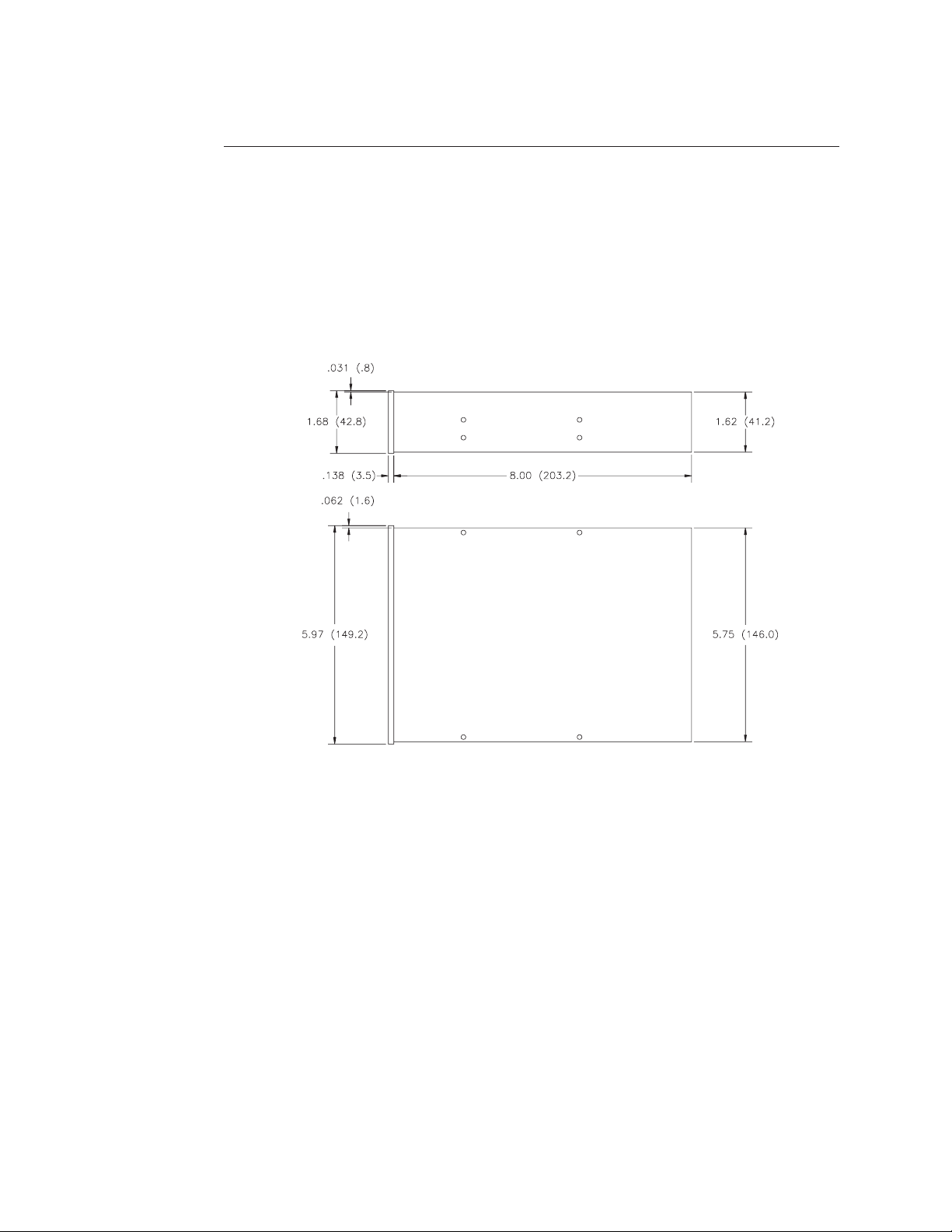
mounting requirements, the tape drive is 1.62 inches high × 5.75
inches wide × 8.00 inches deep (41.2 × 146.0 × 203.2 mm) and weigh
2.6 pounds (1.2 kilograms). Figure 1-7 shows the external dimensions
of the tape drive.
For information about mounting requirements, see Chapter 4.
1 Features
Figure 1-7 External dimensions in inches (and millimeters)
May 1994 EXB-8205and EXB-8505 1-17
(Standard and XL)
Page 32
1 Features
Related Products
This section describes products related to the tape drives.
Integration with Other Exabyte Products
You can purchase the tape drive separately or already integrated with
one of the following Exabyte products:
EXB-210 8mm Library
Mini Tabletop Cartridge Tape Subsystem
EXB-210 8mm Library
The EXB-210 is an 8mm data cartridge library that contains one or two
half-high 8mm tape drives, a ten-cartridge magazine, one fixed
cartridge slot, and a robotic handler. The robotic handler moves the
8mm cartridges between the cartridge storage locations and the tape
drives, greatly reducing the need for manual intervention.
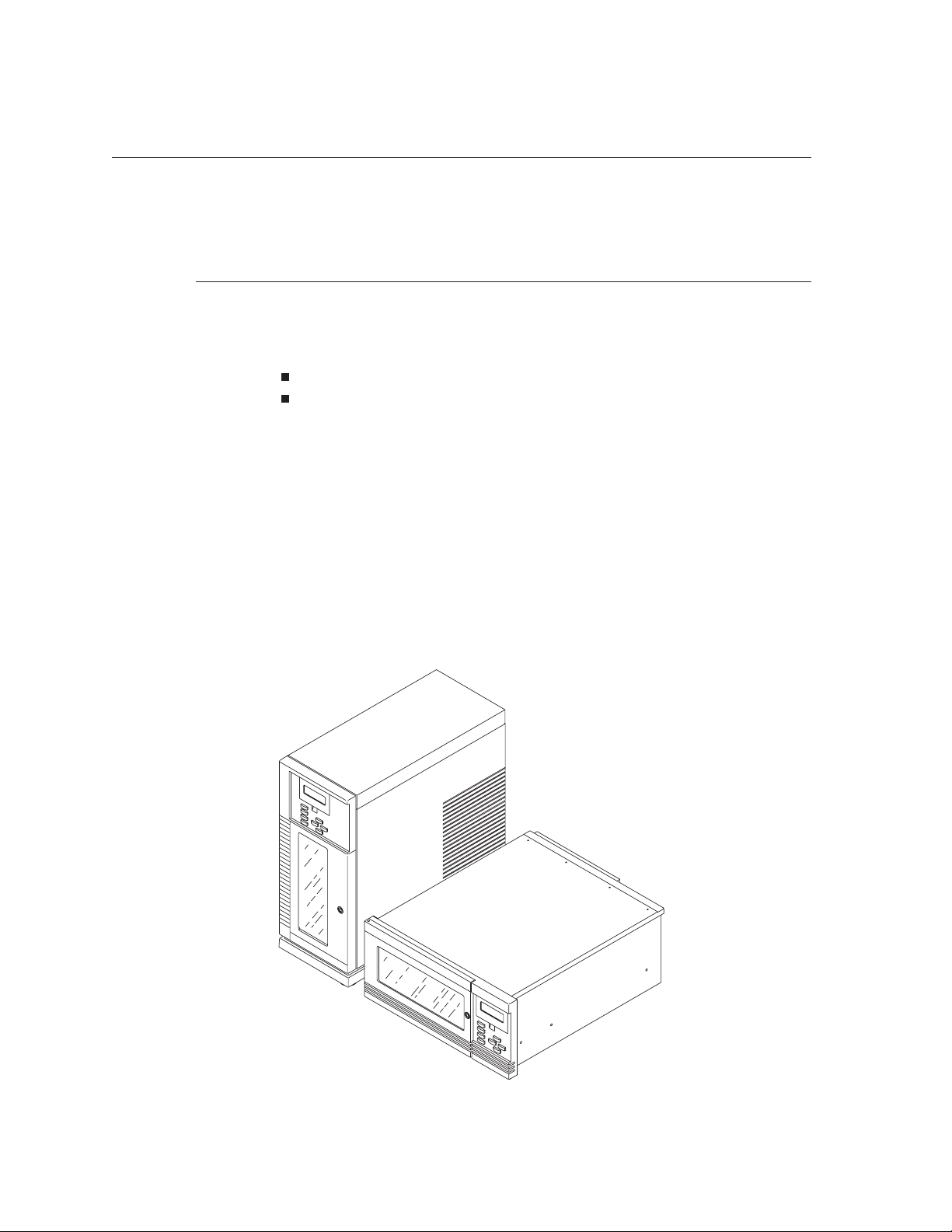
Figure 1-8 shows vertical (stand-alone) and horizontal (rack-mount)
models of the EXB-210.
Figure 1-8 EXB-210 8mm Library
1-18 EXB-8205 and EXB-8505 510504
(Standard and XL)
Page 33
Designed as an easily integrated data management solution, the
EXB-210 provides automated data storage in a SCSI-2 environment.
Operating with an EXB-8505XL and assuming a data compression
ratio of 2:1, the EXB-210 can store up to 154 GBytes on eleven
160m XL data cartridges.
For more information about the EXB-210, refer to the EXB-210 8mm
Library Product Specification.
Mini Tabletop Cartridge Tape Subsystem
The Mini Tabletop Cartridge Tape Subsystem (Mini Tabletop CTS) is
an 8mm tape drive enclosure, which includes a power supply,
thermistor-controlled fan, SCSI connectors, and Monitor port.
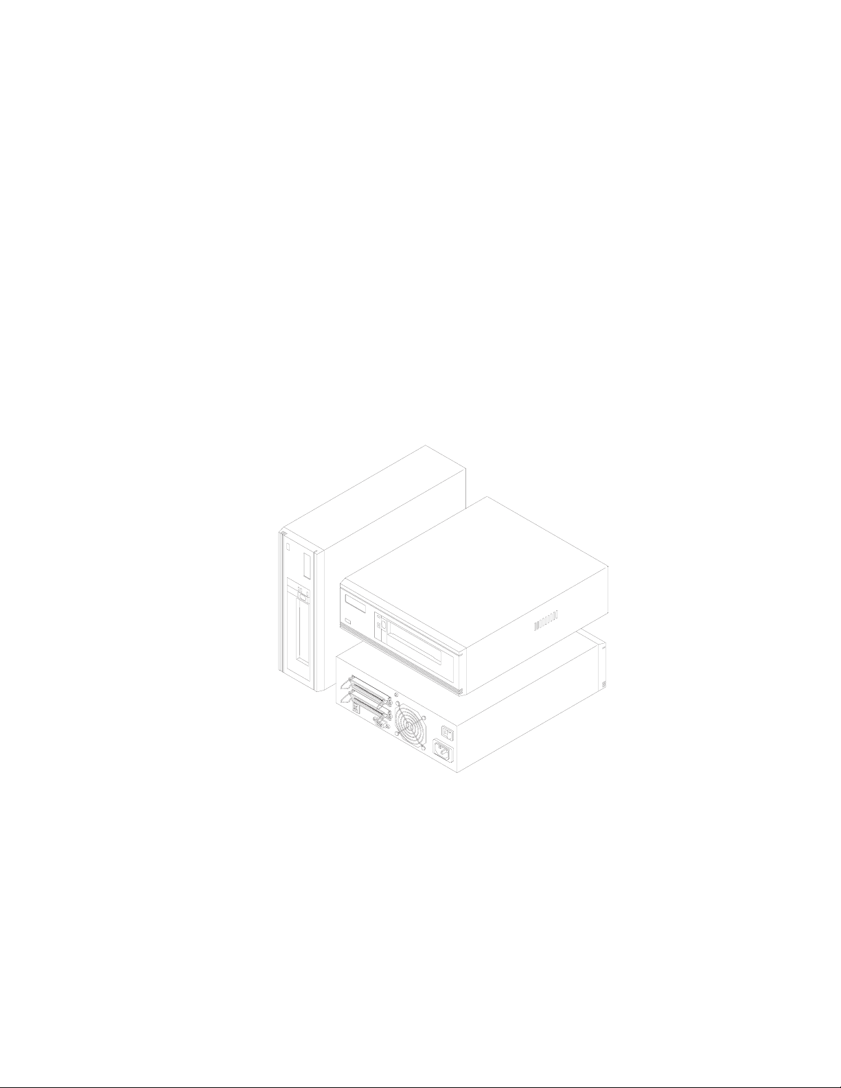
Figure 1-9 shows vertical, horizontal, front, and back views of the
Mini Tabletop CTS.
1 Features
Figure 1-9 Mini Tabletop CTSs with EXB-8505s installed
May 1994 EXB-8205and EXB-8505 1-19
(Standard and XL)
Page 34

1 Features
The Mini Tabletop CTS is lightweight and completely enclosed. It has
an internal, self-switching universal power supply, which allows
continuous operation during limited power interruptions or surges.
The Mini Tabletop CTS also offers maximum EMI/RFI shielding.
A remote SCSI ID switch and two SCSI connectors on the enclosure
provide multiple options in a daisy-chained environment.
For more information about the Mini Tabletop CTS, refer to the Mini
Tabletop Cartridge Tape Subsystem Product Specification.
EXATAPEÔ Data Cartridges
The tape drives use data-quality removable, rewriteable 8mm
metal-particle data cartridges. These data cartridges require no
formatting or other media conditioning before use.
Important Exabyte strongly recommends that you use EXATAPE
#
data-grade media with all Exabyte products, including the
EXB-8205, EXB-8205XL, EXB-8505, and EXB-8505XL. EXATAPE
media meets specifications that are the most stringent in the
industry.
Unlike media available from other manufacturers, EXATAPE media
is specifically controlled for use in a data storage environment and
offers reliability, extended durability, and long-term archivability. In
addition, exclusive use of EXATAPE media with Exabyte 8mm tape
drives has been shown to prolong head and tape life.
Table 1-5 shows EXATAPE data cartridge compatibility with Exabyte
half-high and full-high drives.
1-20 EXB-8205 and EXB-8505 510504
(Standard and XL)
Page 35

Table 1-5 EXATAPE media compatibility with 8mm tape drives
1 Features
EXATAPE
Length
15m
54m
112m
160m XL
Thickness Compatible 8mm Tape Drives
13 µm
13 µm
10 µm
7.7 µm
EXB-8200 and
EXB-8200SX
4444
4444
4444
Do not use Do not use
Important EXATAPE 160m XL media is compatible with the
#
EXB-8205XL and EXB-8505XL only. The EXB-8205 and EXB-8505
will automatically eject these data cartridges.
Although Exabyte full-high 8mm tape drives will accept EXATAPE
160m XL data cartridges, they are not compatible and should not
be used together.
EXB-8500 and
EXB-8500c
EXB-8205 and
EXB-8505
Automatically
ejects
EXB-8205XL
and
EXB-8505XL
4
EXATAPE 160m XL data cartridges offer the same reliability and
performance as all other EXATAPE data cartridges.
All EXATAPE 160m XL data cartridges contain a single Recognition
System stripe located on the tape leader for media identification. The
EXB-8205XL and EXB-8505XL are capable of detecting this stripe,
which they use to distinguish data-quality metal-particle media, such
as EXATAPE, from other 160m media.
To maintain data integrity, the EXB-8205XL and EXB-8505XL
automatically eject 160m data cartridges or equivalent length video
cartridges that are not equipped with the Recognition System stripe.
By rejecting potentially inferior media, the extended length tape
drives ensure greater data reliability and protect the read and write
heads from unnecessary wear.
May 1994 EXB-8205and EXB-8505 1-21
(Standard and XL)
Page 36

1 Features
Exabyte Cleaning Cartridges
Use an Exabyte 8mm Cleaning Cartridge to clean the tape drive. The
Exabyte 8mm Cleaning Cartridge contains a shed-free fabric tape that
traps and removes debris from tape drive heads and tape paths. By
using this cleaning cartridge on a regular basis, you maintain data
integrity and improve reliability of the tape drive.
Exabyte 8mm Cleaning Cartridges come in two sizes: 3c and 12c.
Used in a half-high tape drive, the 3c cartridge offers up to 9 cleaning
passes, and the 12c cartridge can offer as many as 36 cleaning passes.
Details on the cleaning intervals are given in Chapter 4.
Note: If you are using these cleaning cartridges with Exabyte
full-high 8mm tape drives, you will get fewer cleaning passes
per cartridge. Because full-high tape drives have a longer tape
path, more material is required for each cleaning.
CAUTION
The Exabyte 8mm Cleaning Cartridge (or an Exabyte-approved
cleaning cartridge) is the only authorized method for cleaning the
tape drive. Other 8mm cleaning kits can leave fragments in the
tape path or on the heads. If you use any other type of cleaning
material, you will void the tape drive warranty.
1-22 EXB-8205 and EXB-8505 510504
(Standard and XL)
Page 37

Recording Format
This chapter describes the recording formats used by the EXB-8205,
EXB-8205XL, EXB-8505, and EXB-8505XL. It includes information
about the following:
2
Helical-scan recording
Physical format of the recorded tape
Logical format of the recorded tape
May 1994 EXB-8205and EXB-8505 2-1
(Standard and XL)
Page 38
2 Recording Format
Helical-Scan Recording
To increase the amount of data that can be recorded on the tape, the
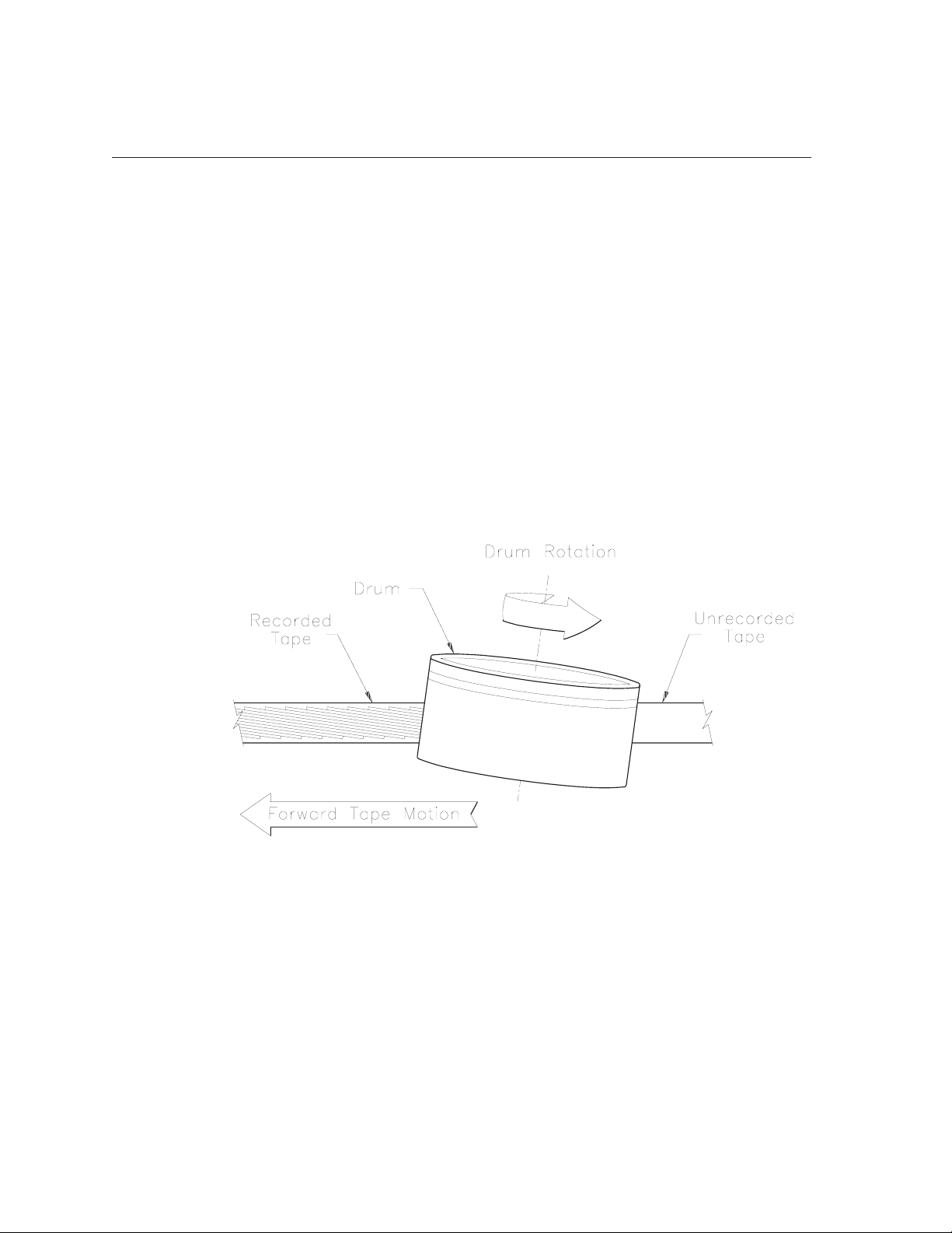
tape drive implements advanced helical-scan recording technology.
Helical-scan recorders write very narrow tracks at an acute angle to
the edge of the tape, as shown in Figure 2-1. This recording method
createsatracklengththatisseveraltimeslongerthanthewidthofthe
tape. Tracks can be accurately positioned by the geometry of the tape
path to precise minimal tolerances, resulting in a very high number of
tracks per inch.
The combination of the helical wrap of the tape around the drum, the
rotation of the head/drum assembly, and the linear motion of the
tape causes the heads to trace a track across the tape that is 2.47 inches
(62.7 millimeters) long, at an acute angle of approximately 5 degrees
to the bottom edge of the tape.
Figure 2-1 Helical-scan recording
2-2 EXB-8205 and EXB-8505 510504
(Standard and XL)
Page 39

Physical Format
This section defines the physical track structure of the tape, including
the types of physical track structures, physical blocks, search fields,
and servo areas.
Physical Track Structure
The EXB-8205 and EXB-8205XL can write data to tape in two types of
physical track structures: 8200 and 8200c. The EXB-8505 and
EXB-8505XL can write data to tape in three types of physical track
structures: 8500/8500c, 8200c, and 8200. These track structures are
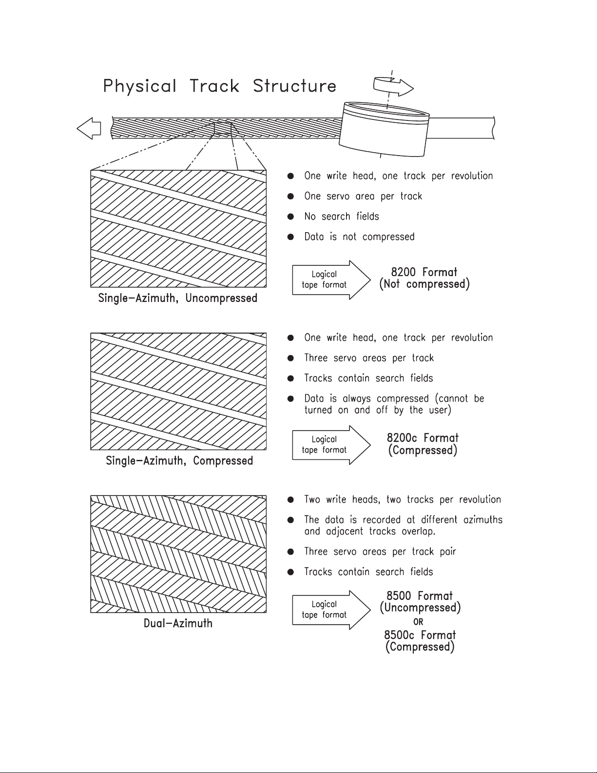
described below. Figure 2-2 shows the relationship between the three
physical track structures and the four logical data formats.
2 RecordingFormat
In 8500/8500c track structure,thetapedrivewritestwo
overlapping tracks to the tape for each revolution of the drum.
Each track contains data blocks, servo areas (track 2 only), clock
sync areas, and search fields. 8500/8500c track structure is also
called dual-azimuth track structure.
Note: 8500 and 8500c physical track structures are identical. Using
the compressed logical format (8500c), the EXB-8505 and
EXB-8505XL compress data before storing it in physical
blocks. Using the uncompressed logical format (8500), the
tape drives do not compress data.
In 8200c track structure, the tape drive writes a single track to the
tape for each revolution of the drum. Like 8500/8500c tracks, each
track contains data blocks, servo areas, clock sync areas, and
search fields. 8200c track structure is also called single-azimuth
compressed track structure.
In 8200 track structure, the tape drive writes a single track to tape
for each revolution of the drum. Each track contains data blocks
and one servo area for accurate positioning of the tape. 8200 track
structure is also called single-azimuth uncompressed track structure.
May 1994 EXB-8205and EXB-8505 2-3
(Standard and XL)
Page 40
2 Recording Format
Figure 2-2 Relationship of 8mm physical track structures to logical data formats
2-4 EXB-8205 and EXB-8505 510504
(Standard and XL)
Page 41
8500/8500c Physical Track Structure
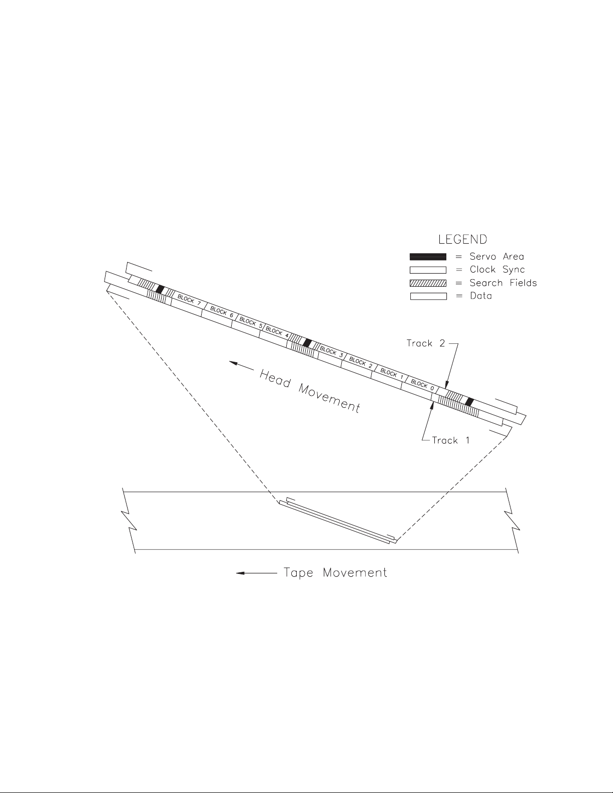
In 8500/8500c format, an EXB-8505 or EXB-8505XL uses the W1 and
W2 heads to write two partially overlapping physical tracks on the
tape for each revolution of its head/drum assembly. The width of
each track is 15.5 µm. During a read operation, the tape drive uses the
R1 and R2 heads to read the two tracks.
Figure 2-3 shows the physical track structure on a tape written in 8500
and 8500c format.
2 RecordingFormat
Figure 2-3 Physical track structure for 8500 and 8500c format
May 1994 EXB-8205and EXB-8505 2-5
(Standard and XL)
Page 42
2 Recording Format
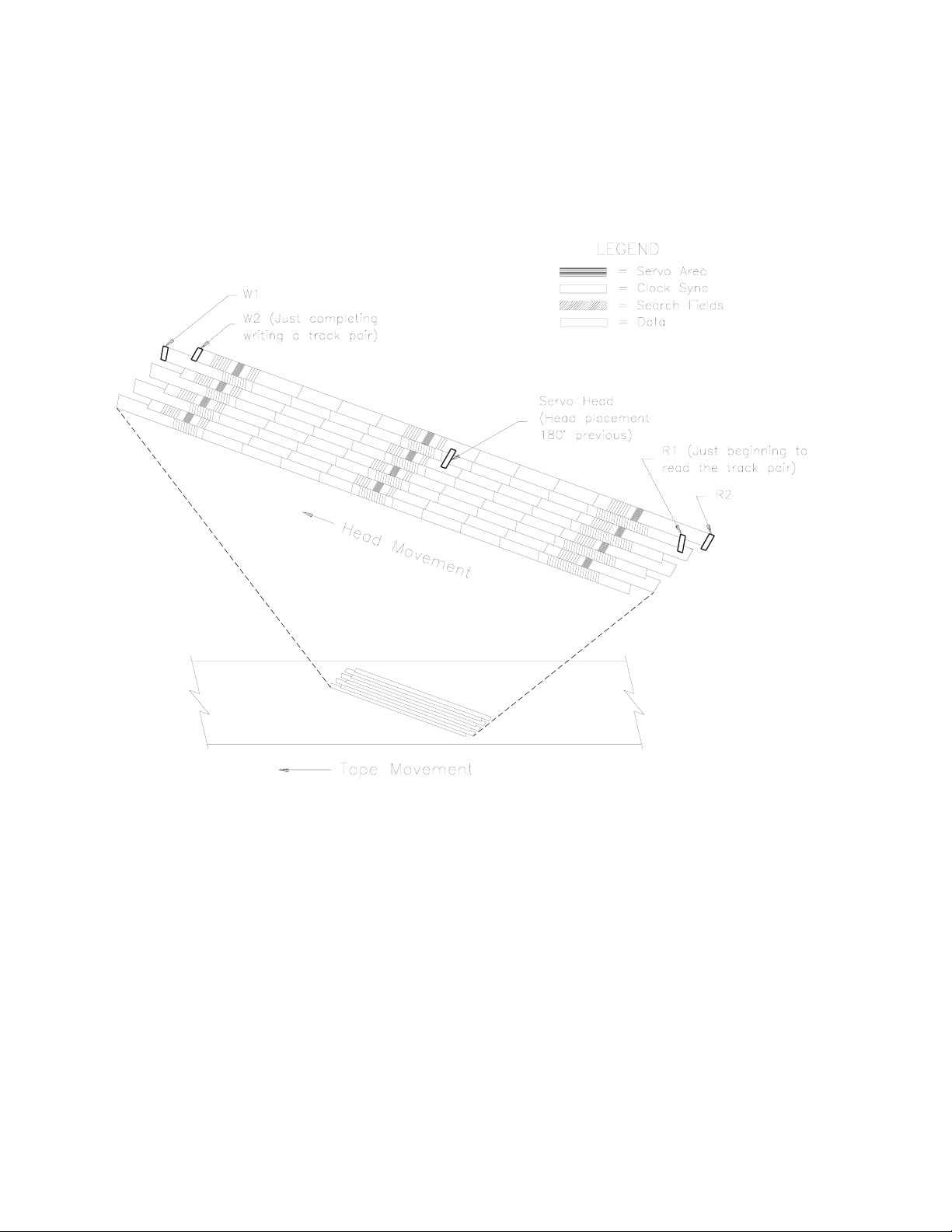
Figure 2-4 shows the position of the EXB-8505 and EXB-8505XL’s
write (W1, W2), read (R1, R2), and servo heads, relative to the tracks
as the heads pass across the tape when the tape drive is writing or
reading 8500 and 8500c format tapes.
Figure 2-4 Position of the tape drive’s heads relative to the tracks (8500/8500c format)
8200c and 8200 Physical Track Structure
In 8200c and 8200 formats, the tape drive writes one physical track on
the tape for each revolution of the head/drum assembly. The width of
the track is 25 µm. During a read operation, the tape drive reads a
single track. The EXB-8505 and EXB-8505XL use the W2 write head
and R2 read head for these operations.
Figure 2-5 shows the physical track structure on a tape written in
8200c format. Figure 2-6 shows the physical track structure on a tape
written in 8200 format.
2-6 EXB-8205 and EXB-8505 510504
(Standard and XL)
Page 43
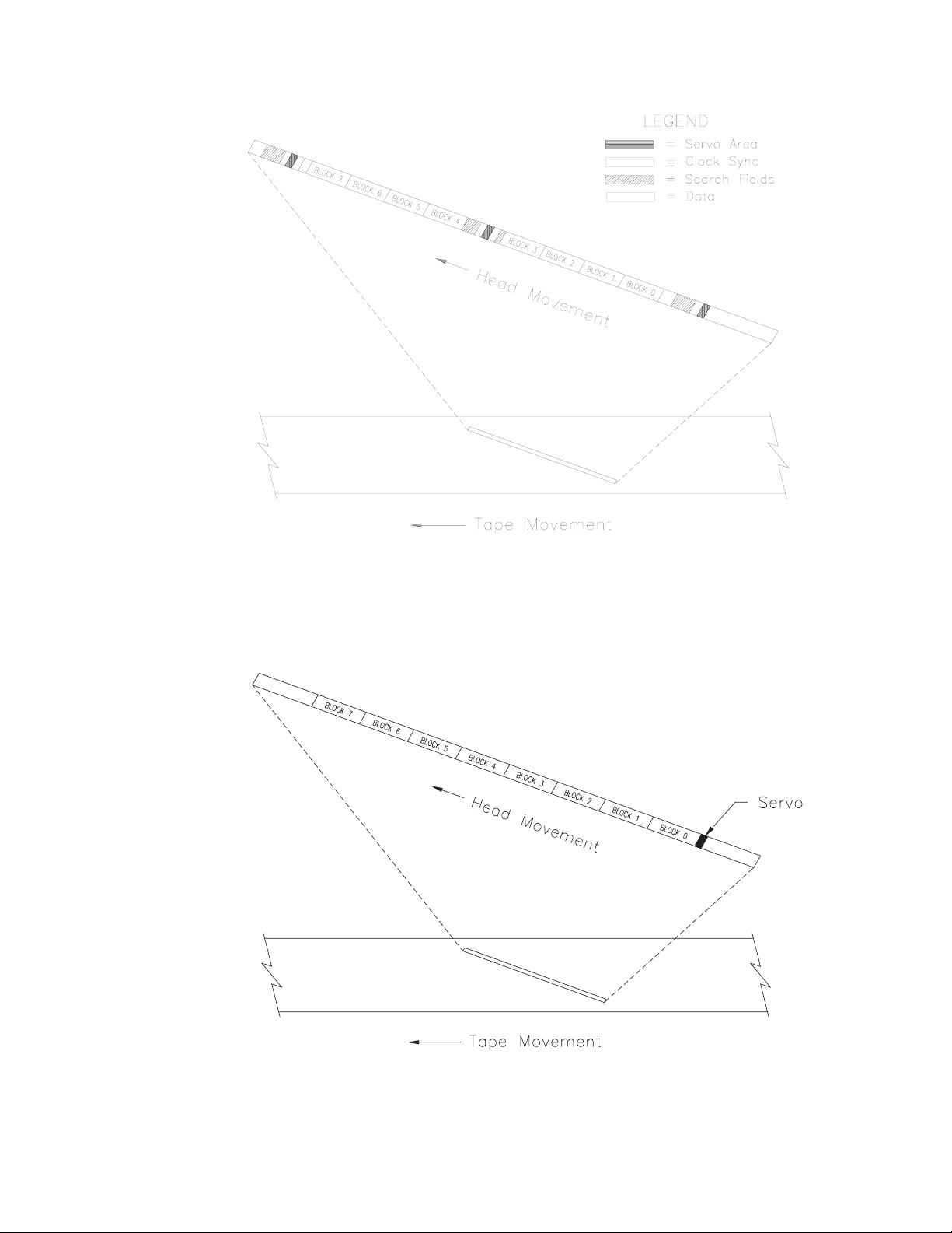
2 RecordingFormat
Figure 2-5 Physical track structure for 8200c track format
Figure 2-6 Physical track structure for 8200 track format
May 1994 EXB-8205and EXB-8505 2-7
(Standard and XL)
Page 44
2 Recording Format
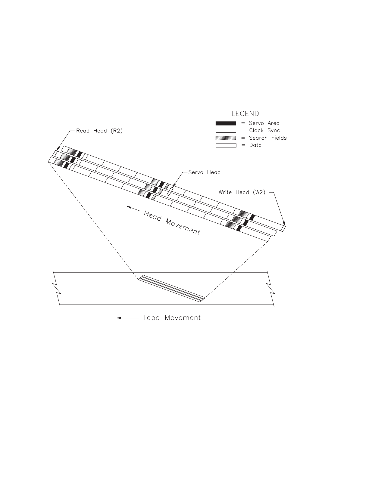
Figure 2-7 shows the position of the tape drive’s write head, read
head, and servo head relative to the tracks as the heads pass across
the tape when the tape drive is reading and writing 8200c format
tapes. (For the EXB-8505 and EXB-8505XL, the W2 write head and R2
read head positions are shown.)
Figure 2-7 Position of the tape drive’s heads relative to the tracks (8200c format)
2-8 EXB-8205 and EXB-8505 510504
(Standard and XL)
Page 45
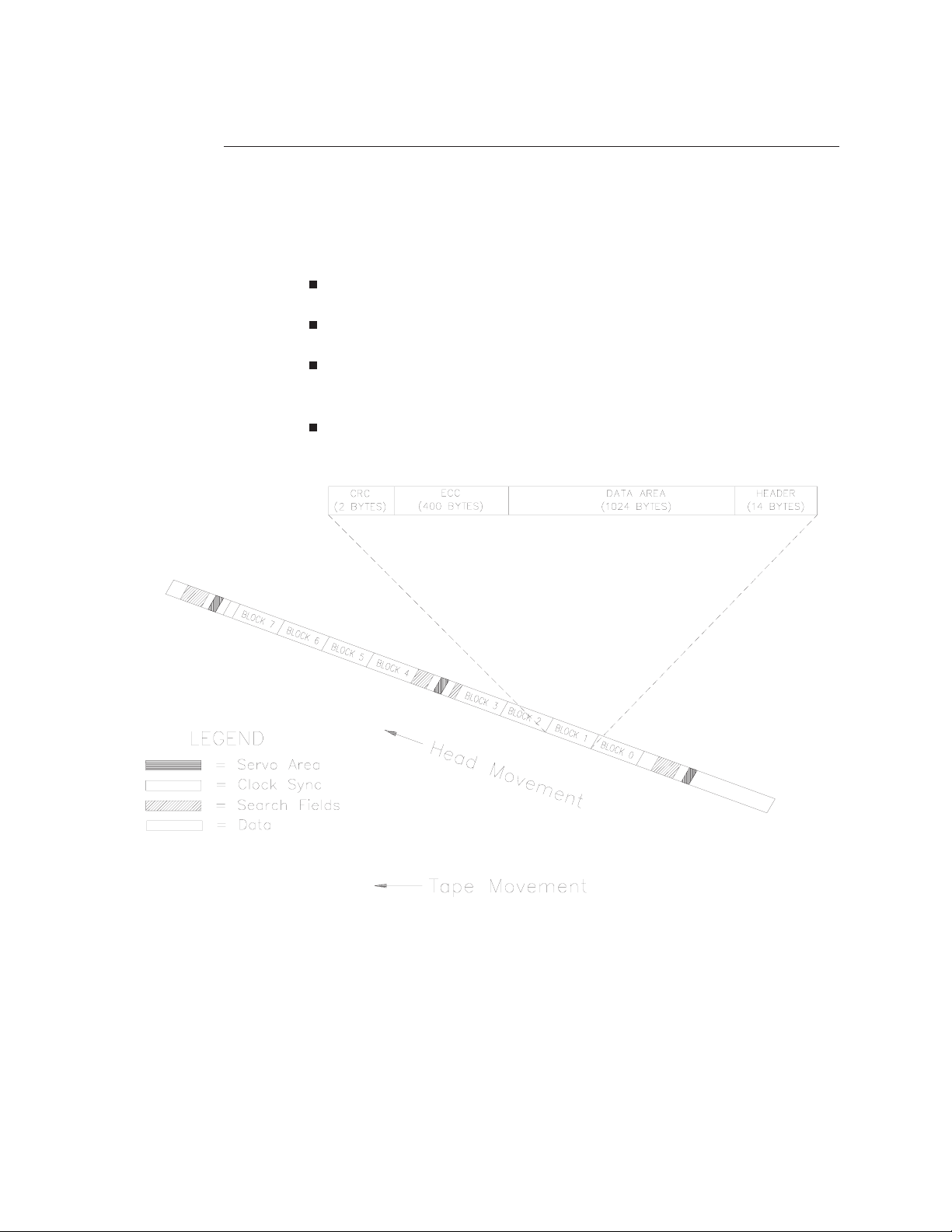
Physical Blocks
For all three physical track formats, each physical track contains eight
physical blocks. A physical block can contain user data or other
information. As shown in Figure 2-8, a physical block containing user
data includes the following information:
2 bytes of cyclic redundancy check (CRC) data
400 bytes of error correction code (ECC) data
1,024 bytes of uncompressed user data or 2,048 of compressed
user data (assuming a 2:1 compression efficiency)
14 bytes of header information
2 RecordingFormat
Figure 2-8 Physical block format for all logical formats (8200c or 8500/8500c physical track structure shown)
Note: The physical block header, ECC data, and physical block CRC
data do not affect the data capacity of the tape.
May 1994 EXB-8205and EXB-8505 2-9
(Standard and XL)
Page 46

2 Recording Format
Search Fields
Servo Areas
For 8500/8500c and 8200c track structures, each track contains search
fields used for high-speed search. (Figure 2-8 shows where search
fields are located in a track.) The search fields are the only areas of the
tape that are read during a high-speed search. The search field data
contains information for locating files and blocks and detecting the
end-of-data (EOD) mark during high-speed searches.
Note: Tapes written in 8200 format are SCSI-1 compatible and do
not contain search fields. For this reason, 8200 format tapes do
not support high-speed search. In addition, the EXB-8205,
EXB-8205XL, EXB-8505, and EXB-8505XL do not support the
EXB-8200SX high-speed search feature.
For all three physical track structures, each track contains servo areas
that the tape drive uses to read tapes written by other tape drives.
Each servo area contains a signal that the servo head detects and uses
to control linear tape velocity. This track-following servo process
results in accurate positioning of the track under the read head.
The servo scheme is based on the geometry of the track positions.
Each servo area consists of one servo data signal burst surrounded by
an erase (margin) signal. The tape drive places servo areas in the
following locations, based on physical track format:
In 8200 format, the tape drive places a servo area at the beginning
of each track (as shown in Figure 2-6).
In 8200c format, the tape drive places a servo area at the
beginning, middle, and end of every track (as shown in
Figure 2-7).
In 8500/8500c format, the tape drive places a servo area at the
beginning, middle, and end of every other track (as shown in
Figure 2-4).
Note: RefertotheEXB-8200 8mm Cartridge Tape Subsystem Product
Specification for information about track-following servo for
8200 format.
2-10 EXB-8205 and EXB-8505 510504
(Standard and XL)
Page 47

Recording Parameters
Table 2-1 shows the recording parameters for the EXB-8205,
EXB-8205XL, EXB-8505, and EXB-8505XL. The table includes the
parameters for tape drives writing and reading data in three physical
formats.
Table 2-1 Recording parameters
2 RecordingFormat
Parameter
Tape width 8.00 mm
Track length
(data + servo)
Tracks per
revolution
Track pitch
Track width
Track density 64.506 trk/mm
Areal recording
density
Drum speed 1831.055 rpm 1831.055 rpm 1922.607 rpm
b
c
Tape drives reading and writing in this physical format:
8500/8500c
(0.315 in)
62.651 mm
(2.47 in.)
211
15.5 µm
(0.000610 in)
15.5 µm
(0.000610 in)
(1638.455 trk/in)
144.23 Mfc/mm
(93.052 Mfc/in2)
a
2
8200c 8200
8.00 mm
(0.315 in)
62.651 mm
(2.47 in)
31.0 µm
(0.001221 in)
25.0 µm
(0.000984 in)
32.253 trk/mm
(819.226 trk/in)
72.115 Mfc/mm
(46.526 Mfc/in2)
2
8.00 mm
(0.315 in)
71.628 mm
(2.82 in)
31.0 µm
(0.001221 in)
25.0 µm.
(0.000984 in)
32.254 trk/mm
(819.253 trk/in)
68.68 Mfc/mm
(44.312 Mfc/in2)
2
Tape speed 11.079 mm/sec
(0.436 ips)
Track angle 4.9 degrees 4.9 degrees 4.9 degrees
Wrap angle 221 degrees 221 degrees 221 degrees
a EXB-8505 and EXB-8505XL only.
b In 8200c and 8500/8500c formats, servo information is embedded in three places along the length of the track.
In 8200 format, servo information is embedded at the beginning of the track.
c Tracks per revolution is the number of tracks written or read for each revolution of the rotating drum assembly.
11.079 mm/sec
(0.436 ips)
11.633 mm/sec
(0.458 ips)
May 1994 EXB-8205and EXB-8505 2-11
(Standard and XL)
Page 48

2 Recording Format
Logical Format
The following sections describe the logical characteristics of the
information recorded on the tape. The logical tape format consists of
the logical beginning of tape (LBOT) mark, followed by any number
of tracks up to the limit for the data cartridge. These tracks can
include logical blocks of data, gap blocks and gap bytes, filemarks,
setmarks, and end-of-data information.
Supported Logical Formats
The EXB-8205 and EXB-8205XL can write user data in the following
logical tape formats:
8200c (compressed)
8200
The EXB-8505 and EXB-8505XL can write user data in any of the
following logical tape formats:
8500c (compressed)
8500
8200c (compressed)
8200
See Figure 2-2 for information about the correspondence between
logical tape formats and physical formats.
2-12 EXB-8205 and EXB-8505 510504
(Standard and XL)
Page 49

Logical Blocks
A logical block contains user data that is transferred from the host to
the tape drive. Logical blocks can have fixed or variable lengths,
which can be intermixed on the tape. The tape drive supports
uncompressed logical block sizes from 1 to 240 KBytes.
For information about setting the logical block size, refer to the
EXB-8205 and EXB-8505 SCSI Reference.
Logical Block Compression
When writing data in 8500c and 8200c formats, the tape drive
compresses logical blocks of user data before placing them in the
physical blocks. Thus, each physical block contains a compressed
representation of the original user data. Assuming that the
compression algorithm allows user data to be compressed an average
of two times, each physical block written by the tape drive in
compressed format can contain, on average, the compressed
equivalent of 2,048 bytes of user data.
2 RecordingFormat
Note: The actual compression ratio achieved by the tape drive in
8500c and 8200c formats depends on the type of data to be
compressed.
For more information about compression, refer to Chapter 3.
Logical Block Packing
To optimize tape capacity when writing tapes in 8200c, 8500, or 8500c
formats, the tape drive packs logical blocks of user data into physical
blocks. Each 1,024-byte physical block on tape can contain multiple
logical blocks (for example, two 512-byte uncompressed logical blocks
can be written in one physical block). To prevent losing data capacity
when small logical block sizes are used, the tape drive can begin
writing a logical block in one physical block and end in a subsequent
physical block.
Note: In 8200 format, logical blocks are not packed. Only one or
part of one logical block can be written in each physical block.
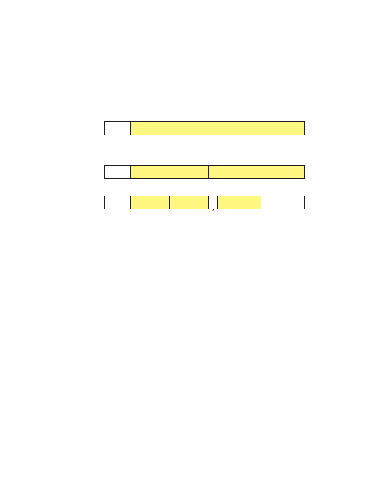
Figure 2-9 shows three examples of how logical blocks can be written
into one 1,024-byte physical block.
May 1994 EXB-8205and EXB-8505 2-13
(Standard and XL)
Page 50
2 Recording Format
8200 format: Header 1,024 bytes
Other formats:
In 8200 format, each physical block contains one header and one
logical block. In 8200c, 8500, and 8500c formats, each physical block
includes a 14-byte header that can define only two logical blocks. If
the physical block contains more than two logical blocks, the tape
drive adds an additional two-byte header in the data field for each
logical block after the second one.
Header and 1 logical block
Header and 2 logical blocks
Header 512 bytes 512 bytes
Header, 2 logical blocks, header, 1 logical block, and free space
Header 256 bytes 256 bytes 256 bytes 254 bytes free
Figure 2-9 Logical block packing (one physical block)
2-byte header
2-14 EXB-8205 and EXB-8505 510504
(Standard and XL)
Page 51
Gap Bytes
A gap byte is a byte containing undefined data that the tape drive uses
to fill empty space in a physical block. The tape drive may
automatically write gap bytes in the following cases:
2 RecordingFormat
At the end of a write operation.
Before writing a filemark.
Before writing a setmark (EXB-8505 or EXB-8505XL only).
When it is physically impossible to start the next logical block in
the physical block because less than three bytes are available.
(This is because the two-byte header and at least one data byte
must be present in the first physical block before the logical block
can spill over to a second physical block.)
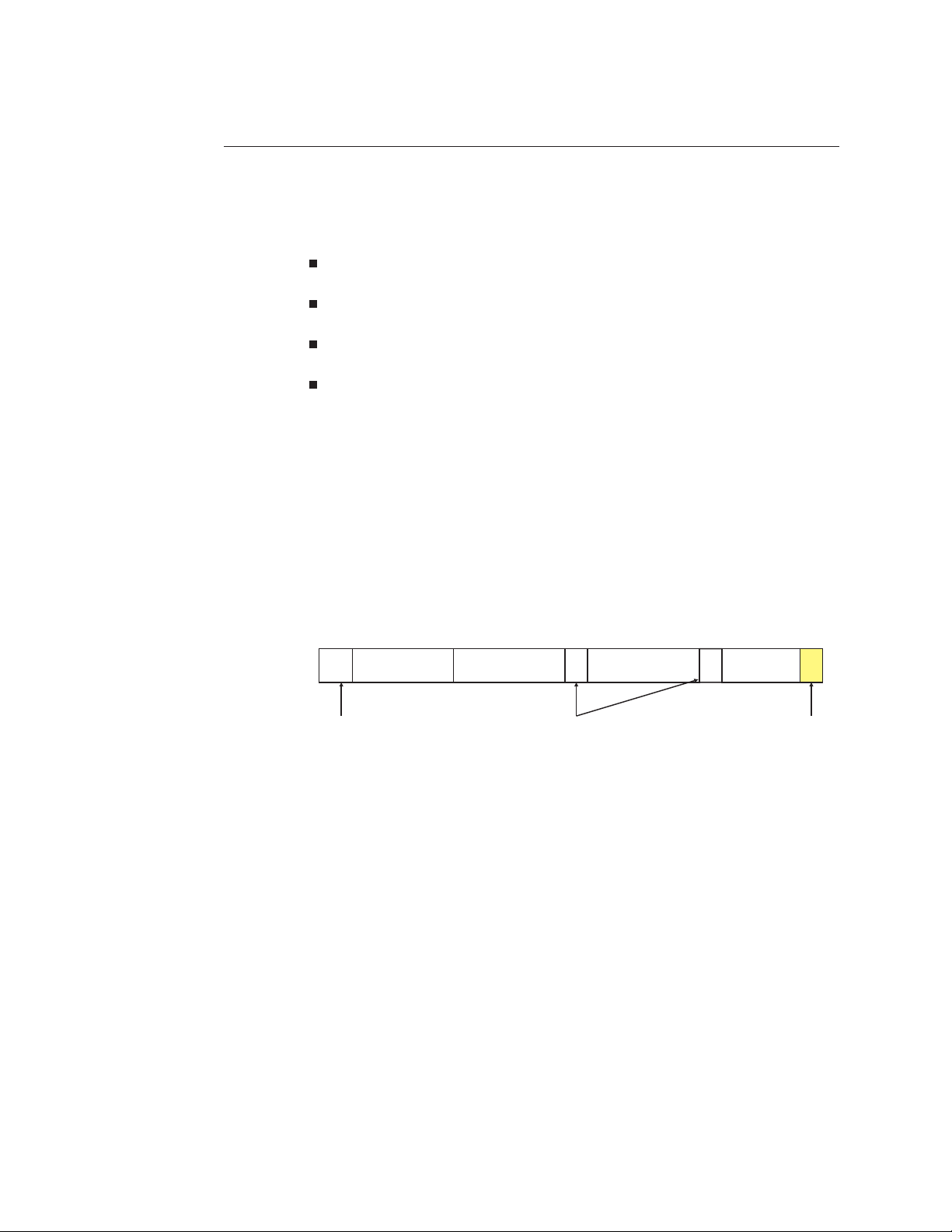
Figure 2-10 shows how gap bytes can be used to fill empty space at
the end of a physical block. Gap bytes cannot be accessed by any SCSI
command.
Header, 2 logical blocks, header, 2 logical blocks, and 2 gap bytes
256 bytes 256 bytes 256 bytes 250 bytes
2-byte headers 2 gap bytes14-byte header
Figure 2-10 Gap bytes (one physical block)
May 1994 EXB-8205and EXB-8505 2-15
(Standard and XL)
Page 52
2 Recording Format
Gap Blocks and Gap Tracks
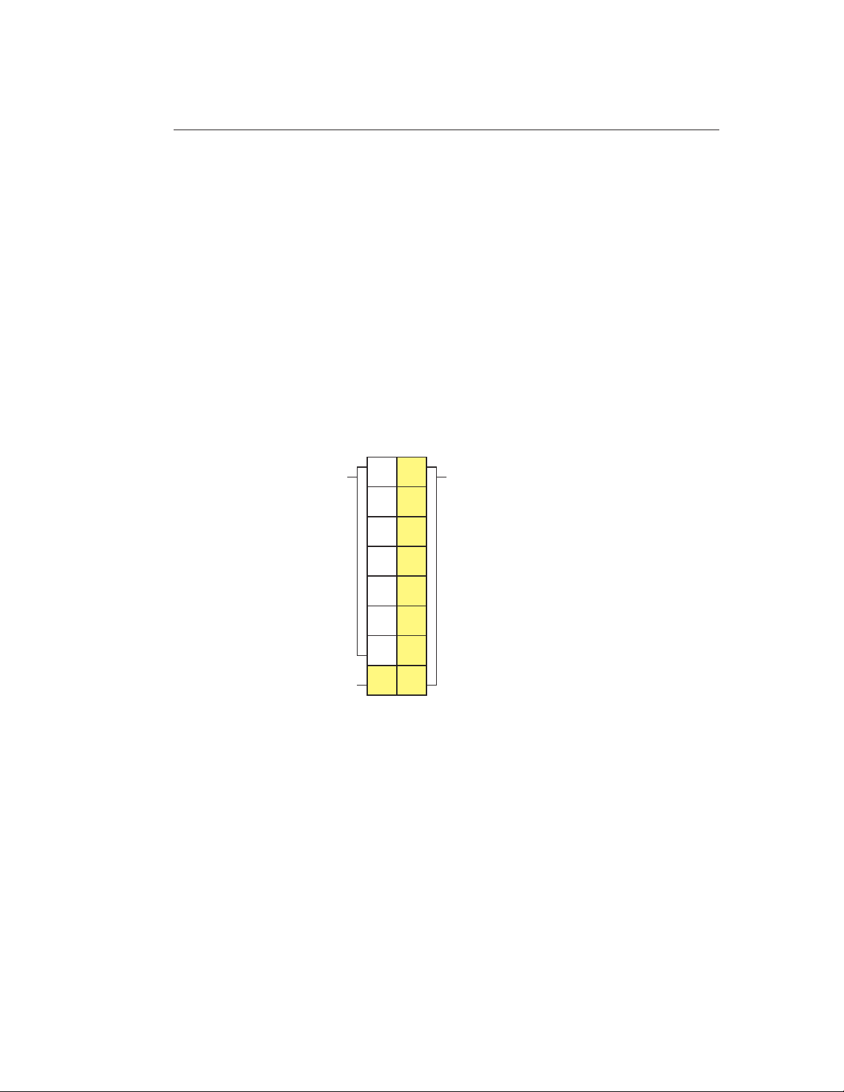
A gap block is a physical block containing 1,024 gap bytes. A gap track
is a physical track containing eight gap blocks. When the tape drive
stops at the end of a write operation, it writes at least one gap track
following the last track containing data blocks. In 8200 or 8200c
format, the tape drive writes one gap track. In 8500 or 8500c format, it
can write two g ap tracks.
The gap track provides the track orientation required to append data.
When a subsequent write operation begins, the controller repositions
the tape and records the data on a track adjacent to the gap track.
Figure 2-11 shows two tracks, one with seven data blocks and one gap
block, and one with a gap track. Gap blocks cannot be accessed by
any SCSI command.
7datablocks
1 gap block
Figure 2-11 One gap block and one gap track in two physical tracks
1 gap track
2-16 EXB-8205 and EXB-8505 510504
(Standard and XL)
Page 53
Filemarks
Filemarks enable the initiator to locate particular blocks of data on the
tape quickly during a high-speed search. By using a SPACE filemark
(11h) command, the initiator can position the tape to the data marked
by filemarks at up to 75 times the normal tape speed (or up to 10
times the normal tape speed when reading an 8200 format tape).
Depending on the format, the tape drive can write either a long or
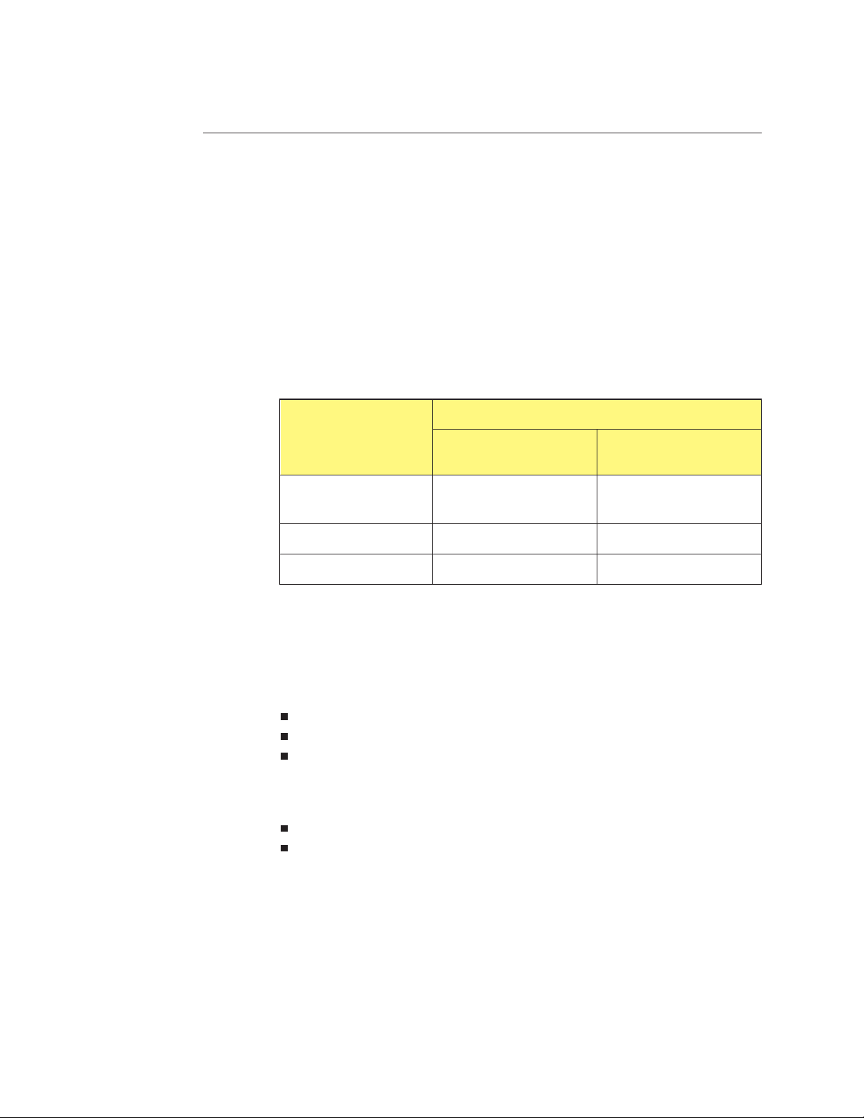
short filemark. Table 2-2 shows the type and size of filemarks for each
format type.
Table 2-2 Type and size of filemarks for each format
Tape format
Type and size of filemarks
Long filemark
(KBytes)
2 RecordingFormat
Short filemark
(KBytes)
8500 or
8500c
8200
8200c 2,160 1
Long Filemarks
A long filemark in either 8500 or 8500c format consists of six tracks of
information:
Two gap tracks at the beginning
Two tracks of filemark physical blocks
Two gap tracks at the end
A long filemark in 8200c or 8200 format consists of the following:
An erase gap equivalent in length to 249 tracks
21 tracks (168 blocks) of long filemark physical blocks
The information in the filemark physical blocks identifies the
filemark’s number and location on the tape and cannot be accessed or
changed by the user. The gap tracks at the beginning and end allow
file append and file splice operations. The tape drive may write
additional gap tracks and gap blocks before the filemark to ensure
that all data has been written to tape correctly or to complete tracks
that are not completely filled with data blocks.
48 1
2,160 184
May 1994 EXB-8205and EXB-8505 2-17
(Standard and XL)
Page 54

2 Recording Format
Short Filemarks
Setmarks (EXB-8505 and EXB-8505XL only)
In 8500, 8500c, and 8200c formats, a short filemark consists of a single,
1-KByte physical block. This block contains information identifying
the filemark’s number and location on the tape.
In 8200 format, a short filemark consists of 21 tracks of information.
When the EXB-8505 or EXB-8505XL is writing in 8500c format, you
can issue a WRITE FILEMARKS (10h) command to write one or more
setmarks to tape. Setmarks provide an additional way to indicate data
boundaries on the tape; in a sense, they can be thought of as
“hierarchically superior” filemarks.
Each setmark is 48 KBytes long and consists of the following:
Two gap tracks at the beginning
Two tracks of setmark physical blocks
Two gap tracks at the end
You can issue a SPACE (11h) command to space to setmarks;
however, you can also use a MODE SELECT (15h) command to
suppress setmark detection during read, verify, space block, and
space filemark operations.
EndofData(EOD)
When writing tapes in 8500, 8500c, or 8200c format, the tape drive
writes an end-of-data (EOD) mark after the last data written to tape.
In 8500 and 8500c formats, the EOD mark consists of one or more gap
tracks, erase gaps, and 600 tracks of end-of-data blocks. In 8200c
format, the EOD mark consists of 249 erase gap tracks and 600 tracks
of end-of-data blocks.
These tracks are used when the initiator issues a SPACE (11h)
command to locate the last data written to tape. The tape drive
overwrites the EOD mark when it writes additional data to tape.
In 8200 format, there is no EOD mark, but you can space to the end of
data.
2-18 EXB-8205 and EXB-8505 510504
(Standard and XL)
Page 55

Track and Block Counts
The number of tracks and physical blocks on the tape depend on the
following markers:
Physical beginning of tape (PBOT). PBOT is located at the point
on the tape where the translucent leader material is attached to
the media. This position is detected by an optical sensor in the
tape transport mechanism.
Logical beginning of tape (LBOT). When you issue a write
operation at the beginning of tape, the tape drive automatically
records LBOT at approximately 29 inches (74 cm) from PBOT. The
LBOT area includes tracks of LBOT information, which are used
to indicate the LBOT’s location, to calibrate the servo system and
to indicate whether the tape was written in uncompressed or
compressed format. The data contained in the LBOT blocks
cannot be altered or accessed by the user.
2 RecordingFormat
Logical end o f tape (LEOT). LEOT is determined by the number
of recorded tracks that occur after LBOT. For this purpose,
lengths of erased segments are converted into an equivalent
number of tracks.
Physical end of tape (PEOT). PEOT is located at the point on the
tape where the translucent trailer material is attached to the
media. This position is detected by an optical sensor in the tape
transport mechanism.
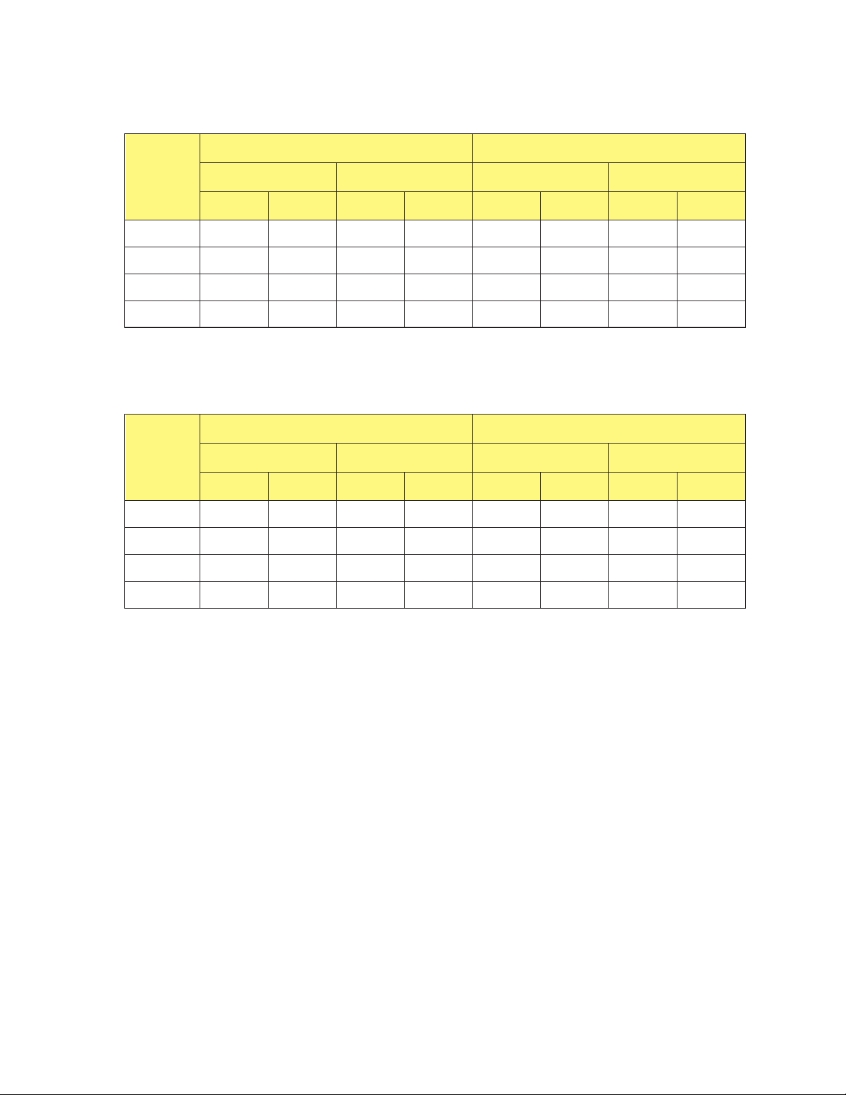
The number of tracks between LBOT and LEOT depends on the type
and length of tape. Table 2-3 and Table 2-4 list the following
information for tapes written in various formats:
The number of tracks and 1,024-byte physical blocks between
LBOT and LEOT
The approximate number of tracks and 1,024-byte physical blocks
that occur between LEOT and PEOT
May 1994 EXB-8205and EXB-8505 2-19
(Standard and XL)
Page 56
2 RecordingFormat
Table 2-3 Track and physical block counts for 8200 and 8200c formats
LBOT to LEOT LEOT to PEOT*
EXATAPE
Size
15m 8C44h 35,908 46220h 287,264 11A9h 4,521 8D48h 36,168
54m 22FF2h 143,346 117F90h 1,146,768 114Eh 4,430 8A70h 35,440
112m 46000h 286,720 230000h 2,293,760 45B0h 17,840 22D8h 142,720
160m XL 696F9h 431,865 34B7C8h 3,454,920 19B0h 6,576 CD84h 52,612
*Track and block counts from LEOT to PEOT are approximate.
Number of tracks Number of blocks Number of tracks Number of blocks
Hex Decimal Hex Decimal Hex Decimal Hex Decimal
Table 2-4 Track and physical block counts for 8500 and 8500c formats
LBOT to LEOT LEOT to PEOT*
EXATAPE
Size
Number of tracks Number of blocks Number of tracks Number of blocks
Hex Decimal Hex Decimal Hex Decimal Hex Decimal
15m 11888h 71,816 8C440h 574,528 954h 2,388 4AA0h 19,104
54m 45FE4h 286,692 22FF20h 2,293,536 229Eh 8,862 114F0h 70,896
112m 93568h 603,496 49AB40h 4,827,968 22A2h 8,866 11510h 70,928
160m XL D2DF2h 863,730 696F90h 6,909,840 3361h 13,153 19B08h 105,224
*Track and block counts from LEOT to PEOT are approximate.
May 1994 EXB-8205and EXB-8505 2-21
(Standard and XL)
Page 57

3
Functional Description
This chapter describes the functional features of the EXB-8205,
EXB-8205XL, EXB-8505, and EXB-8505XL, including write and read
operations.
May 1994 EXB-8205 and EXB-8505 3-1
(Standard and XL)
Page 58
3 Functional Description
Write Operations
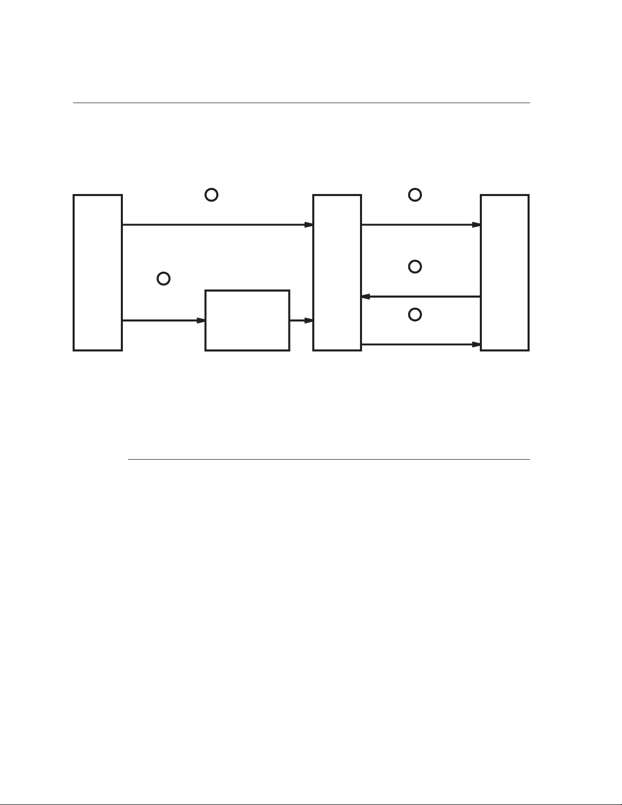
Figure 3-1 provides a high-level overview of the tape drive’s flow of
data during a write operation.
1
Data not tobe compressed
SCSI
bus
Figure 3-1 Data flow during a write operation
2
Data to be
compressed
Compression
circuit
Data Flow and DataCompression
The data-flow process during a write operation is outlined below.
(The steps below correspond to the circled numbers in Figure 3-1.)
These steps are described in further detail in the rest of this section.
Data
buffer
3
Data writtento tape
4
Read-after-write
5
Rewrite (if necessary)
Tape
¬ If you select uncompressed format (8200 or 8500) for the tape,
the data goes directly from the SCSI bus to the tape drive’s
1-MByte DRAM data buffer. (Data transfers between the SCSI
bus and the buffer occur asynchronously or synchronously.)
If you select compressed format (8200c or 8500c) for the tape, the
tape drive looks at the currently active MODE SELECT
parameters to see if data compression has been turned on.
Note: If you select 8200c format, data compression is always on;
youcannotturnitoff.
3-2 EXB-8205and EXB-8505 510504
(Standard and XL)
Page 59

3 Functional Description
If data compression is turned on, the data goes from the SCSI
bus to the compression integrated circuit where it is compressed
and then decompressed. The tape drive performs a Compression
Integrity Check™ by comparing the decompressed data to the
original data.
If the decompressed data does not match the original data, the
tape drive indicates that a compression error has occurred and
does not write the data to tape.
If the decompressed data matches the original data or if data
compression was turned off, the tape drive appends two bytes
of CRC data to each logical block. Then, it transfers the data to
its data buffer.
Note: The tape drive compresses data written to tape at an
average ratio of 2:1. However, the actual compression
ratio achieved depends on the type of data to be
compressed.
® Once the motion threshold is exceeded in the data buffer, tape
motion begins, ECC and physical-block CRC bytes are
integrated with each physical block, and data is written to tape.
¯ The tape drive performs a read-after-write check on the written
data to ensure that the data on tape was written accurately.
° If necessary, the tape drive rewrites the data.
Logical Block CRC
The tape drive adds two bytes of cyclic redundancy check (CRC) data
to every logical block written in compressed format. These bytes add
an extra check to ensure that the user data is compressed and
decompressed accurately.
Note: These logical block CRC bytes are in addition to the two bytes
of physical block CRC data that the tape drive adds to every
physical block on tape.
Adding logical block CRC bytes to each logical block reduces the data
capacity of the tape by two bytes for every logical block. For example,
if you are writing 1,024-byte logical blocks, the data capacity of the
tape will be reduced by 0.2% (that is, 2 ÷ 1,024 × 100%).
May 1994 EXB-8205 and EXB-8505 3-3
(Standard and XL)
Page 60

3 Functional Description
Data Compression Monitoring
Streaming and Start/Stop Modes
The tape drive constantly monitors the compression ratio to
determine whether compressing the data will actually decrease the
size of the data set. When a logical block expands (as it might, for
example, when it has already been compressed by the initiator), the
tape drive automatically switches to uncompressed format. It remains
in this format until it encounters a compressible logical block. Then, it
switches back to the compressed format.
The data buffer enables the tape drive to operate as either a streaming
tape device or as a start/stop tape device. When the tape drive
transfers data to the 1-MByte data buffer, the data buffer’s formatter
performs the following tasks:
Formats logical user data blocks into physical blocks
Appends tag, address, and index information to each data block
The mode of operation (streaming or start/stop) depends on the rate
that data can be transferred between the initiator and the tape drive,
as follows:
The tape drive operates in streaming mode if the initiator can
sustain a minimum of:
1 MByte per second for 8500c format (EXB-8505 and
•
EXB-8505XL only)
500 Bytes per second for 8500 format (EXB-8505 and
•
EXB-8505XL only)
500 KBytes per second for 8200c format
•
262.5 KBytes per second for 8200 format
•
Note: These values assume a 2:1 compression ratio for 8500c and
8200c formats.
The tape drive operates in start/stop mode if the initiator cannot
sustain these minimum transfer rates; starting and stopping occur
automatically.
3-4 EXB-8205and EXB-8505 510504
(Standard and XL)
Page 61

Thresholds During a Write Operation
In start/stop mode, the motion threshold controls the starting and
stopping of tape motion. In streaming mode, the reconnect threshold
controls the rate of disconnects and reconnects between the tape drive
and the initiator. The values of both of these thresholds can be
changed with a MODE SELECT command.
Motion Threshold
In a start/stop write operation, the initiator-to-buffer transfer speed is
slower than the buffer-to-tape transfer speed. In this mode of
operation, the motion threshold value represents the minimum
amount of data that must be in the tape drive’s 1-MByte DRAM data
buffer before tape motion will start. When the initiator sends data to
the tape drive, the tape drive waits until the buffer reaches the motion
threshold to begin writing. Then it writes data to tape until the buffer
is empty.
3 Functional Description
The buffer allows the tape drive to operate with fewer starts and
stops, reducing wear on the tape and the tape drive.
Reconnect Threshold
In a streaming write operation, the initiator-to-buffer transfer rate is
equal to or greater than the buffer-to-tape transfer rate. In this mode
of operation, the tape drive writes data to tape continually. When the
buffer becomes full, the tape drive disconnects from the initiator, and
the initiator is free to perform other tasks.
For the tape drive to continue streaming, the initiator must begin
sending data again before the buffer is empty. The reconnect
threshold value represents the minimum amount of free space that
must be in the tape drive’s 1-MByte buffer before the tape drive will
reconnect to the initiator to accept additional data. When the
reconnect threshold value is exceeded, the tape drive reconnects to
the initiator and data transfer resumes until the buffer is full.
May 1994 EXB-8205 and EXB-8505 3-5
(Standard and XL)
Page 62

3 Functional Description
Error Detection, Correction, and RecoveryProcedures
Error Correction Code (ECC)
As the tape drive writes data to tape, it integrates error correction
code (ECC) and physical-block cyclic redundancy check (CRC) bytes
with each physical block. After it writes data, the tape drive uses the
ECC and CRC to perform a read-after-write check to ensure data
reliability. By using read-after-write error checking and sophisticated
error correction procedures, the tape drive offers a non-recoverable
error rate of less than one bit in 10
The Reed/Solomon ECC algorithms can correct a burst as long as 264
consecutive bytes in error and as many as 80 additional random
errors in each physical data block. The ECC is capable of multiple
burst and random error corrections. It has been designed to be
extremely effective against the types of error patterns that may occur
in cartridge tape subsystems that use helical-scan technology.
17
bits read.
Cyclic Redundancy Check (CRC)
The tape drive also adds two bytes of CRC data to every physical
block on tape. The CRC data is used in the read-after-write check.
Read-After-Write Checking
The tape drive performs a read-after-write check of the recorded user
data to ensure full data reliability. If the tape drive determines that
any data blocks should be rewritten, it rewrites the data without
requiring host intervention or repositioning of the tape.
For more information about how the tape drive corrects data during
the read-after-write check, refer to Chapter 6.
3-6 EXB-8205and EXB-8505 510504
(Standard and XL)
Page 63
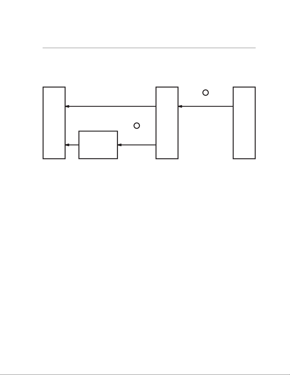
Read Operations
Figure 3-2 provides a high-level overview of the tape drive’s flow of
data during a read operation.
3 Functional Description
1
Uncompressed data
SCSI
bus
Decompression
circuit
Figure 3-2 Data flow during a read operation
The process for reading logical blocks of user data is outlined below.
decompressed
¬ The tape drive reads data from tape, uses ECC to correct errors
as necessary for each physical block, and transfers data to the
data buffer. The read operation continues until the buffer is full
and tape motion stops.
If the data has not been compressed, the data goes directly from
thedatabuffertotheSCSIbus.
2
Data to be
Data
buffer
Data read from tape
Tape
If the data has been compressed, the data goes from the data
buffer to the decompression circuit to be decompressed. Then,
the decompressed data is sent to the SCSI bus.
In either case, the 2-byte logical block CRC, which was
appended when the data was written, is again verified. This
final integrity check assures that all block reconstruction and
decompression was successful.
May 1994 EXB-8205 and EXB-8505 3-7
(Standard and XL)
Page 64

3 Functional Description
Thresholds During a Read Operation
Motion Threshold
The motion threshold controls the starting and stopping of tape
motion. The reconnect threshold controls the rate of disconnects and
reconnects between the tape drive and the initiator.
In a start/stop read operation, the tape-to-buffer transfer speed is
faster than the buffer-to-initiator transfer speed. In this mode of
operation, the motion threshold value represents the minimum
amount of free space that must be in the tape drive’s 1-MByte buffer
before tape motion will start and data will be read from the tape to
the buffer. The read-from-tape operation continues until the buffer is
full and tape motion stops. Tape motion does not restart until the
amount of free space in the buffer once again exceeds the motion
threshold value.
Reconnect Threshold
In a streaming read operation, the tape-to-buffer transfer rate is equal
to or less than the buffer-to-initiator transfer rate. In this mode of
operation, the tape drive reads data from tape continually. When the
buffer becomes empty, the tape drive disconnects from the initiator,
and the initiator is free to perform other tasks.
For the tape drive to continue streaming, the initiator must begin to
accept data again before the buffer is full. The reconnect threshold
valuerepresentstheminimumamountofdatathatmustbeinthe
tape drive’s 1-MByte buffer before the tape drive will reconnect to the
initiator to transfer data from the buffer. When the reconnect
threshold value is exceeded, the tape drive reconnects to the initiator
and data transfer resumes. The data transfer to the initiator continues
until the buffer is empty.
3-8 EXB-8205and EXB-8505 510504
(Standard and XL)
Page 65

4
Requirements for Use
This chapter specifies the requirements for installing, operating,
maintaining, and shipping the EXB-8205, EXB-8205XL, EXB-8505, and
EXB-8505XL. This chapter includes the following sections:
Installation requirements
Operation
Preventive maintenance
Loading new microcode
Shipping requirements
May 1994 EXB-8205 and EXB-8505 4-1
(Standard and XL)
Page 66
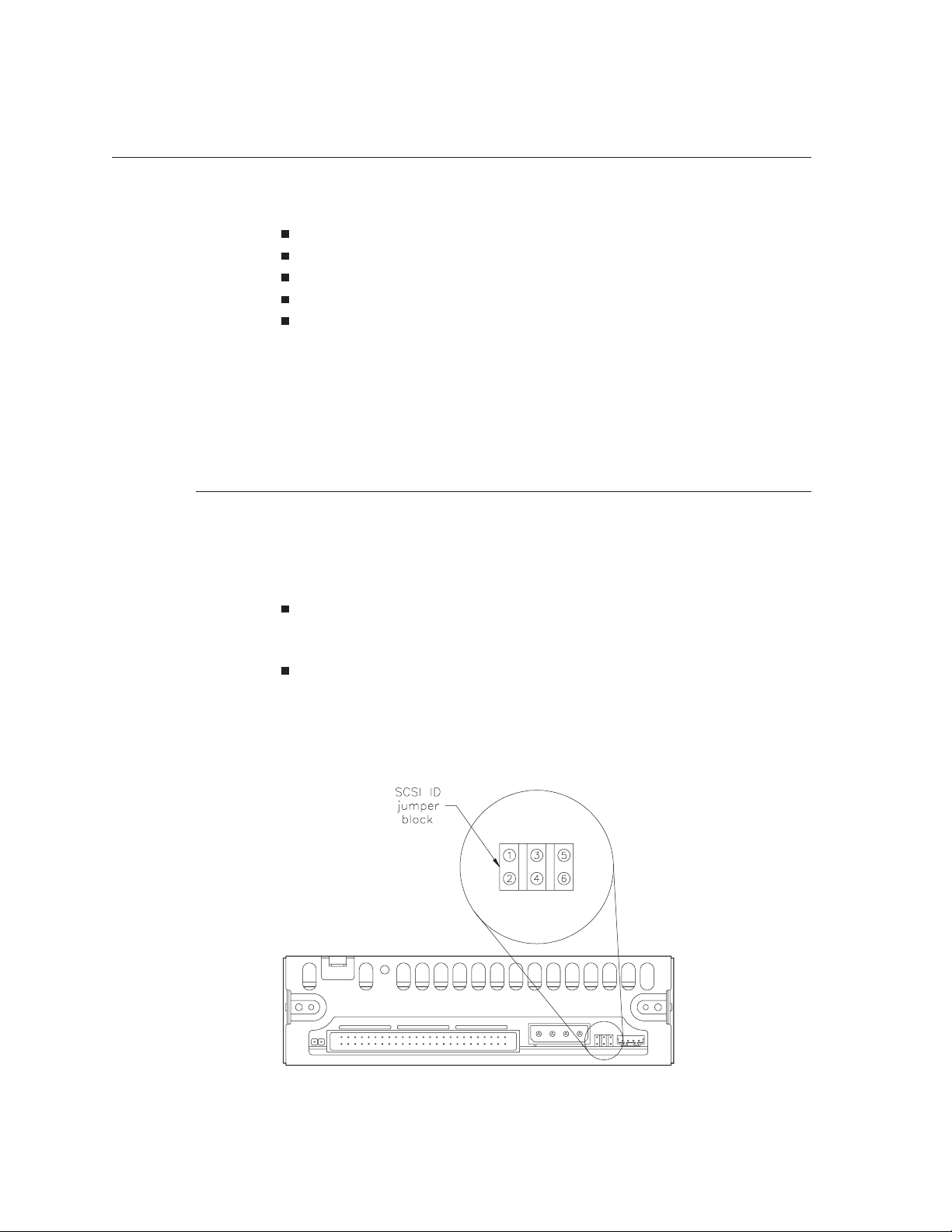
4 Requirements for Use
Installation Requirements
Installing the tape drive involves the following steps:
Setting the SCSI ID
Mounting the tape drive in a mounting frame (if desired)
Terminating the tape drive (if necessary)
Connecting a SCSI cable to the tape drive
Connecting the tape drive to the power supply
This section describes the requirements for installing the tape drive.
For step-by-step instructions for completing installation tasks, refer to
EXB-8205 and EXB-8505 Installation and Operation.
Requirements for Setting theSCSI ID
The SCSI ID is the address asserted by the tape drive during
arbitration. The SCSI ID is set at the factory; if you want to change the
tape drive’s SCSI ID (0 through 7), you can do one of the following:
Remove and reposition the jumpers on the SCSI ID jumper block
onthebackofthetapedrive(seeFigure4-1).
Remove the jumpers and connect a remote switch to the SCSI ID
jumper block. A remote switch is not provided with the tape
drive. Use a female Molex
connector to control the address remotely.
®
22-55-2061 or equivalent cable
Figure 4-1 SCSI ID jumper block on the back panel (single-ended configuration)
4-2 EXB-8205and EXB-8505 510504
(Standard and XL)
Page 67

Note that changes in the SCSI ID setting will not take effect until one
of the following conditions occur:
Normal power-on
The tape drive is reset by a SCSI bus reset
The tape drive receives a Bus Device Reset message
For detailed instructions for setting the SCSI ID, including the pin
assignments for the SCSI ID jumper block, refer to EXB-8205 and
EXB-8505 Installation and Operation.
Requirements for Mounting theTape Drive
The main housing of the tape drive includes three sets of mounting
holes (two sets on the sides and one set on the bottom) to allow for a
number of mounting positions. The tape drive can be mounted either
horizontally or vertically and in a stationary or sliding position.
4 Requirements for Use
When mounting the tape drive, follow these guidelines:
Use either one of the two sets of four mounting holes on the sides
of the tape drive (shown as “A” or “B” in Figure 4-2) or the four
mounting holes on the bottom of the tape drive (shown as “C” in
Figure 4-3).
Use all four holes in whichever set you choose. Do not use
combinations of mounting holes from different sets.
Ensure that the tape drive is securely mounted and that the
chassis is not subject to distortion.
Ensure that no objects such as screw heads, cables, or adjacent
devices are pressing against the frame.
Do not obstruct the ventilation slots of the device. This ensures
that the tape drive can be adequately cooled.
May 1994 EXB-8205 and EXB-8505 4-3
(Standard and XL)
Page 68
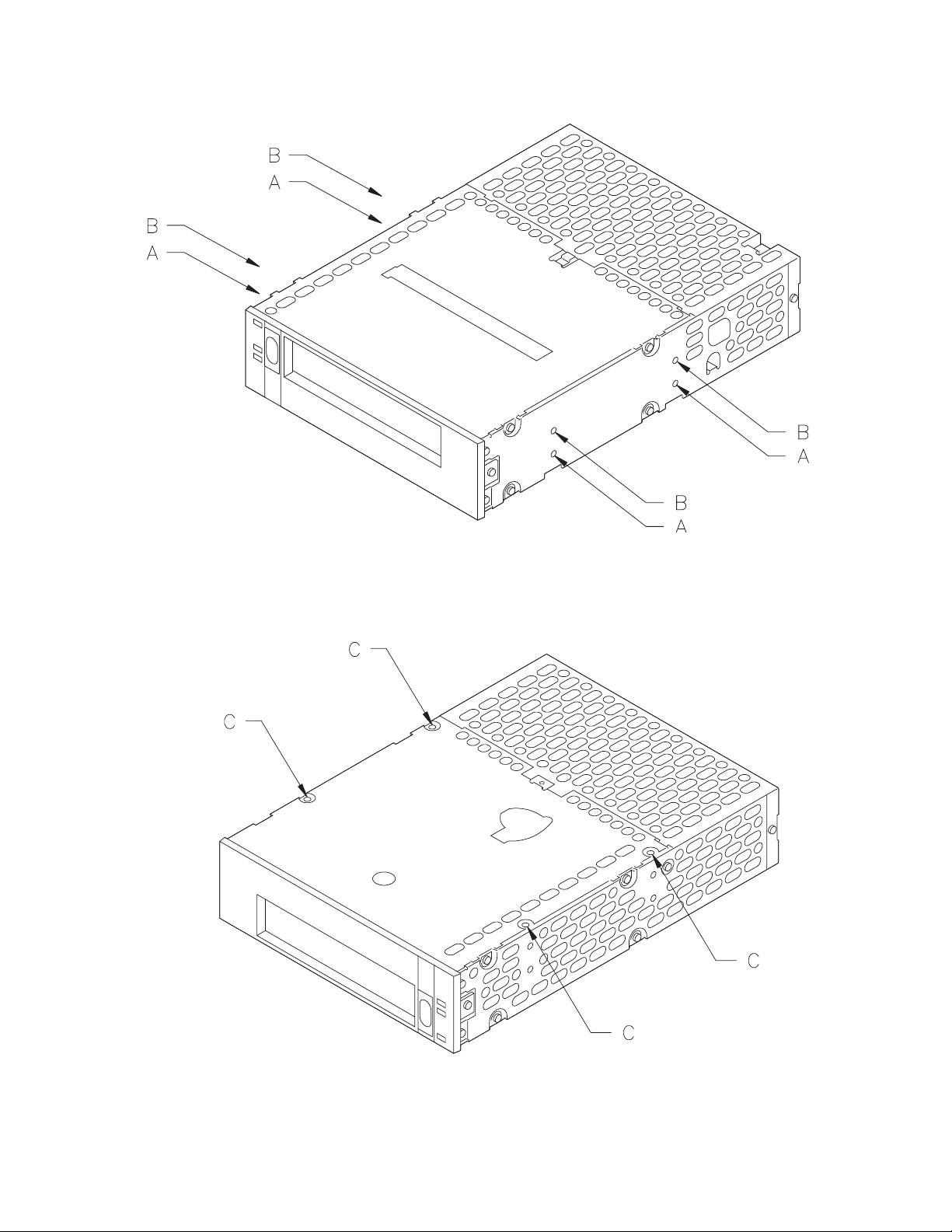
4 Requirements for Use
Figure 4-2 Mounting holes on the sides
Figure 4-3 Mounting holes on the bottom
4-4 EXB-8205and EXB-8505 510504
(Standard and XL)
Page 69
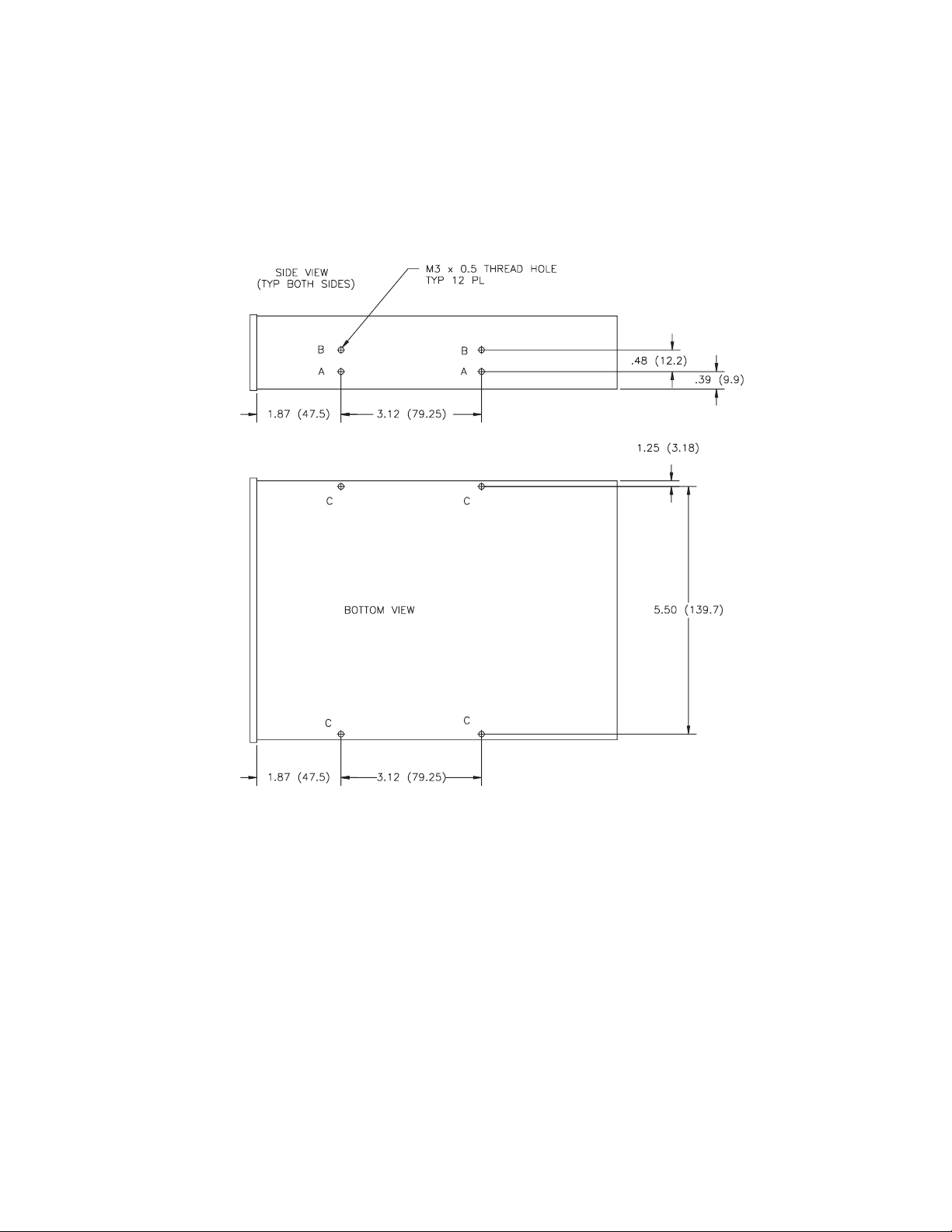
4 Requirements for Use
The mounting holes accommodate M3 × 0.5 × 6 mm screws and are
designed for standard 5.25-inch half-high form factor mounting
requirements. The holes are 0.31 inches (7.9 mm) deep.
Figure 4-4 shows the dimensions for the tape drive’s mounting holes.
Figure 4-4 Mounting hole dimensions in inches (and millimeters)
May 1994 EXB-8205 and EXB-8505 4-5
(Standard and XL)
Page 70

4 Requirements for Use
Requirements for SCSI BusTermination
Terminators for Single-Ended Configuration
IfthetapedriveisthelastdeviceontheSCSIbus,itmustbe
terminated. As described in this section, the termination requirements
for the tape drive depend on whether it uses a single-ended or
differential SCSI configuration.
The single-ended SCSI configuration includes three single in-line
package (SIP) resistor terminators (R-packs). They can be left in place
if the tape drive terminates the SCSI bus or removed if the tape drive
does not terminate the SCSI bus or if external termination is used.
If necessary, the single-ended tape drive can be terminated externally.
To ensure that the tape drive performs to specification, Exabyte
recommends a Methode Electronics, Inc. dataMate
single-ended external terminator.
®
DM103-02-0
Terminators for Differential Configuration
The differential SCSI configuration of the tape drive does not include
internal terminators. If a differential tape drive terminates the SCSI
bus, it must be terminated externally. To ensure that the tape drive
performs to specification, Exabyte recommends a Methode
Electronics, Inc. dataMate DM103-01-0 differential external terminator.
4-6 EXB-8205and EXB-8505 510504
(Standard and XL)
Page 71

Requirements for Connecting aSCSI Cable
The cable for connecting the tape drive to the SCSI bus is not
provided with the tape drive. You must provide a cable that complies
with the appropriate safety and regulatory agency requirements. To
comply with FCC, Canadian DOC, and VDE limits, the tape drive
requires shielded cables when the cables are external to the mounting
enclosure.
Impedance
Ideally, to match the cable terminators, the cable should have a
characteristic impedance of 122 ohms (differential) or 132 ohms
(single-ended). However, since cables with this high of a characteristic
impedance are not generally available, somewhat lower impedances
are acceptable. A characteristic impedance of 100 ohms ± 10% is
recommended for unshielded flat or twisted-pair ribbon cable. A
characteristic impedance greater than 90 ohms is recommended for
shielded cables.
4 Requirements for Use
#
Cable Length
The maximum length of the SCSI cable depends on whether you are
using a single-ended or differential SCSI configuration, as follows:
Important To minimize discontinuities and signal reflections,
Exabyte recommends that cables used on the same bus have the
same impedances.
For single-ended SCSI configurations, the maximum allowable
bus length is 6 meters (19.7 feet). A stub length of no more than
0.1 meters (4 inches) is allowed off the mainline interconnection
within any connected equipment.
For differential SCSI configurations, the maximum allowable bus
length is 25 meters (82 feet). A stub length of no more than
0.2 meters (8 inches) is allowed off the mainline interconnection
within any connected equipment.
May 1994 EXB-8205 and EXB-8505 4-7
(Standard and XL)
Page 72
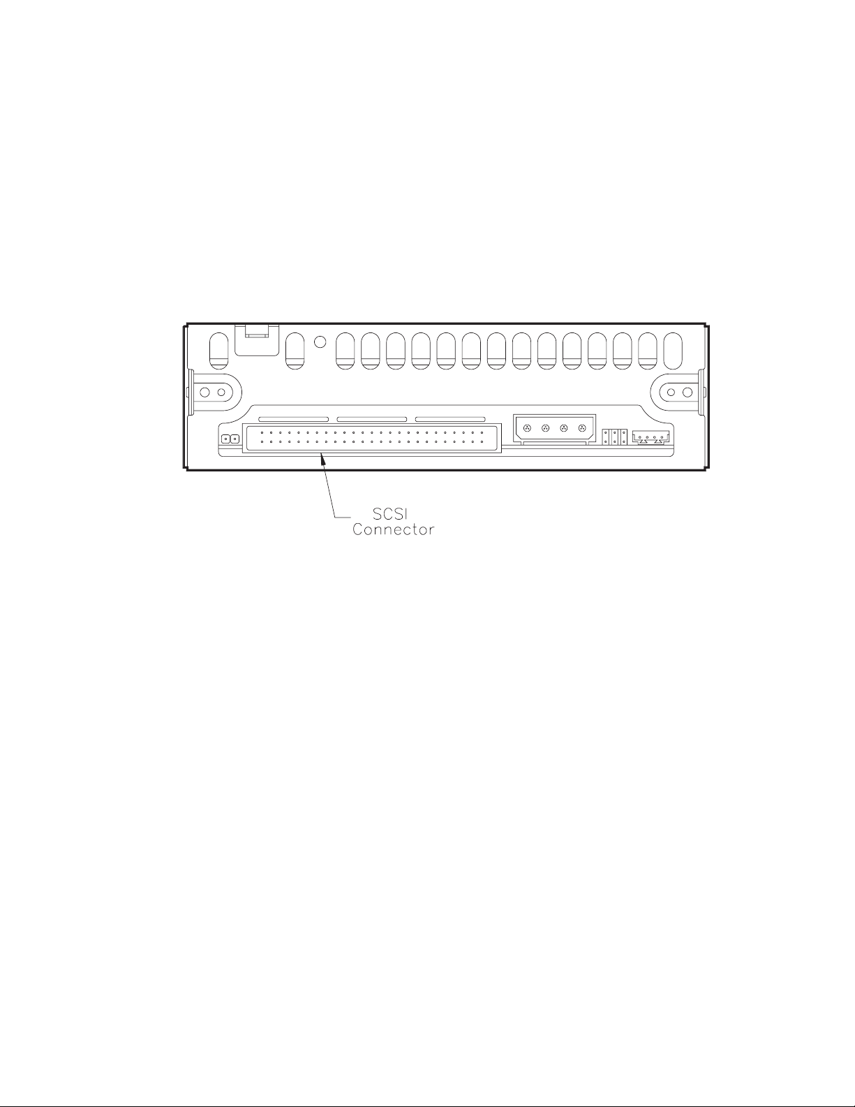
4 Requirements for Use
Primary Conductor
SCSI Cable Connector Requirements
A minimum primary conductor size of 28 AWG is recommended to
minimize noise effects and ensure proper distribution of terminator
power.
The SCSI connector is located at the back of the tape drive, as shown
in Figure 4-5. The connector is a 50-pin male ribbon cable connector.
Thestublengthwithinthetapedriveislessthan50mm.
Figure 4-5 SCSI connector location on the back panel
To connect the tape drive to the SCSI bus, use a 50-pin female ribbon
cable connector (AMP No. 1-746285-0 or equivalent).
Table 4-1 shows the connector pin assignments for differential tape
drives; Table 4-2 shows the connector pin assignments for
single-ended tape drives.
4-8 EXB-8205and EXB-8505 510504
(Standard and XL)
Page 73

4 Requirements for Use
Table 4-1 Connector pin assignments for differential tape drives
Signal Pin Number Signal
SHIELD GROUND 1 2 GROUND
+DB(0) 3 4 –DB(0)
+DB(1) 5 6 –DB(1)
+DB(2) 7 8 –DB(2)
+DB(3) 9 10 –DB(3)
+DB(4) 11 12 –DB(4)
+DB(5) 13 14 –DB(5)
+DB(6) 15 16 –DB(6)
+DB(7) 17 18 –DB(7)
+DB(P) 19 20 –DB(P)
DIFFSENS 21 22 GROUND
GROUND 23 24 GROUND
TERMPWR 25 26 TERMPWR
GROUND 27 28 GROUND
+ATN 29 30 –ATN
GROUND 31 32 GROUND
+BSY 33 34 –BSY
+ACK 35 36 –ACK
+RST 37 38 –RST
+MSG 39 40 –MSG
+SEL 41 42 –SEL
+C/D 43 44 –C/D
+REQ 45 46 –REQ
+I/O 47 48 –I/O
GROUND 49 50 GROUND
May 1994 EXB-8205 and EXB-8505 4-9
(Standard and XL)
Page 74

4 Requirements for Use
Table 4-2 Connector pin assignments for single-ended tape drives
Signal Pin Number*
+DB(0) 2
+DB(1) 4
+DB(2) 6
+DB(3) 8
+DB(4) 10
+DB(5) 12
+DB(6) 14
+DB(7) 16
+DB(P) 18
GROUND 20
GROUND 22
GROUND 24
TERMPWR 26
GROUND 28
GROUND 30
–ATN 32
GROUND 34
–BSY 36
–ACK 38
–RST 40
–MSG 42
–SEL 44
–C/D 46
–REQ 48
–I/O 50
* All odd pins except pin 25 are connected to ground. Pin 25 is left open.
4-10 EXB-8205 and EXB-8505 510504
(Standard and XL)
Page 75

Operation
Power-On Mode
Tape Drive Controls
4 Requirements for Use
This section provides general information about operating the tape
drive. For more detailed instructions, refer to EXB-8205 and EXB-8505
Installation and Operation.
In its normal power-on mode, the tape drive completes a power-on
self-test in approximately 30 seconds. Once the power-on self test is
complete, the tape drive loads the tape (if already inserted), and
positions the tape at LBOT.
The only operator control on the tape drive is the unload button on
the front panel. Pushing this button starts the unload procedure. This
button can also be used to reset the tape drive if a servo error occurs.
The EXB-8205 and EXB-8505 have a smooth unload button. The
EXB-8205XL and EXB-8505XL have a diamond-textured unload
button.
Device States
Figure 4-6 shows the orientation of the green, amber, and dual
green/amber LEDs on the front panel of the EXB-8505 and
EXB-8505XL. Figure 4-7 shows the orientation of the LEDs on the
front panel of the EXB-8205 and EXB-8205XL. The three LEDs are
status indicators.
May 1994 EXB-8205 and EXB-8505 4-11
(Standard and XL)
Page 76
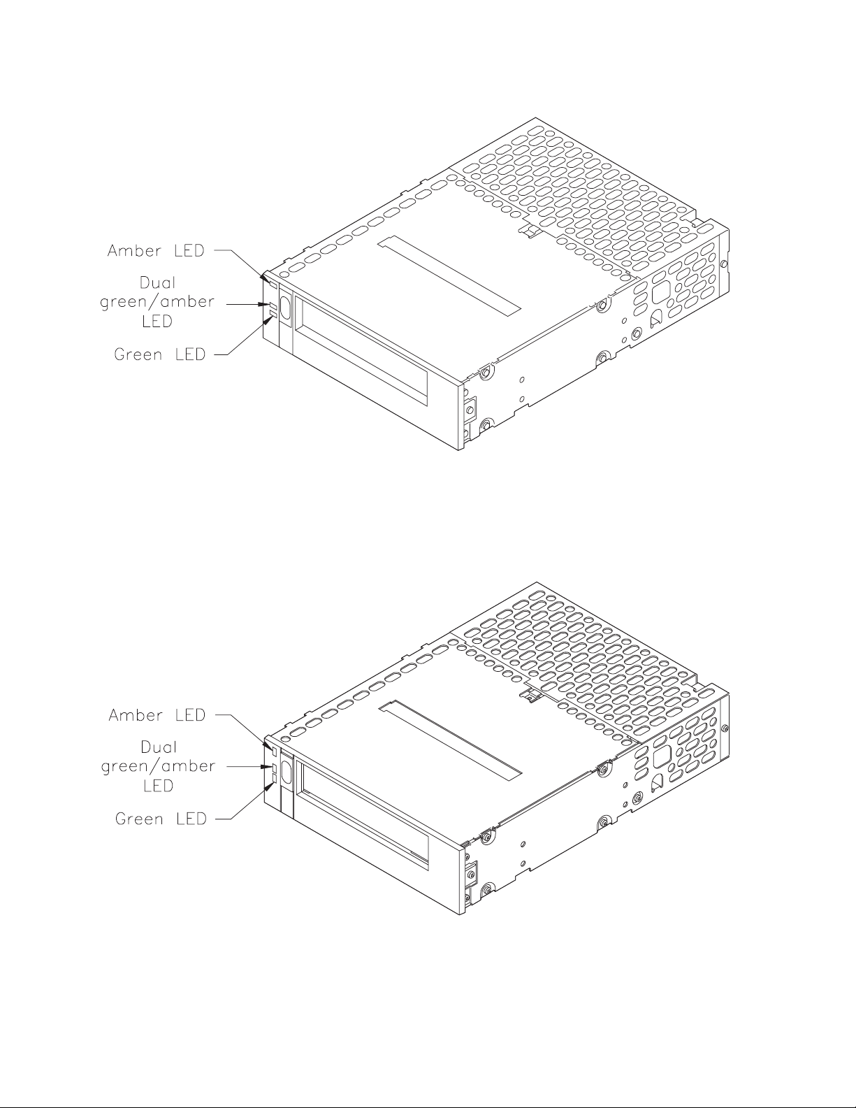
4 Requirements for Use
Figure 4-6 LEDs on the faceplate of the EXB-8505 and EXB-8505XL
Figure 4-7 LEDs on the faceplate of the EXB-8205 and EXB-8205XL
4-12 EXB-8205 and EXB-8505 510504
(Standard and XL)
Page 77
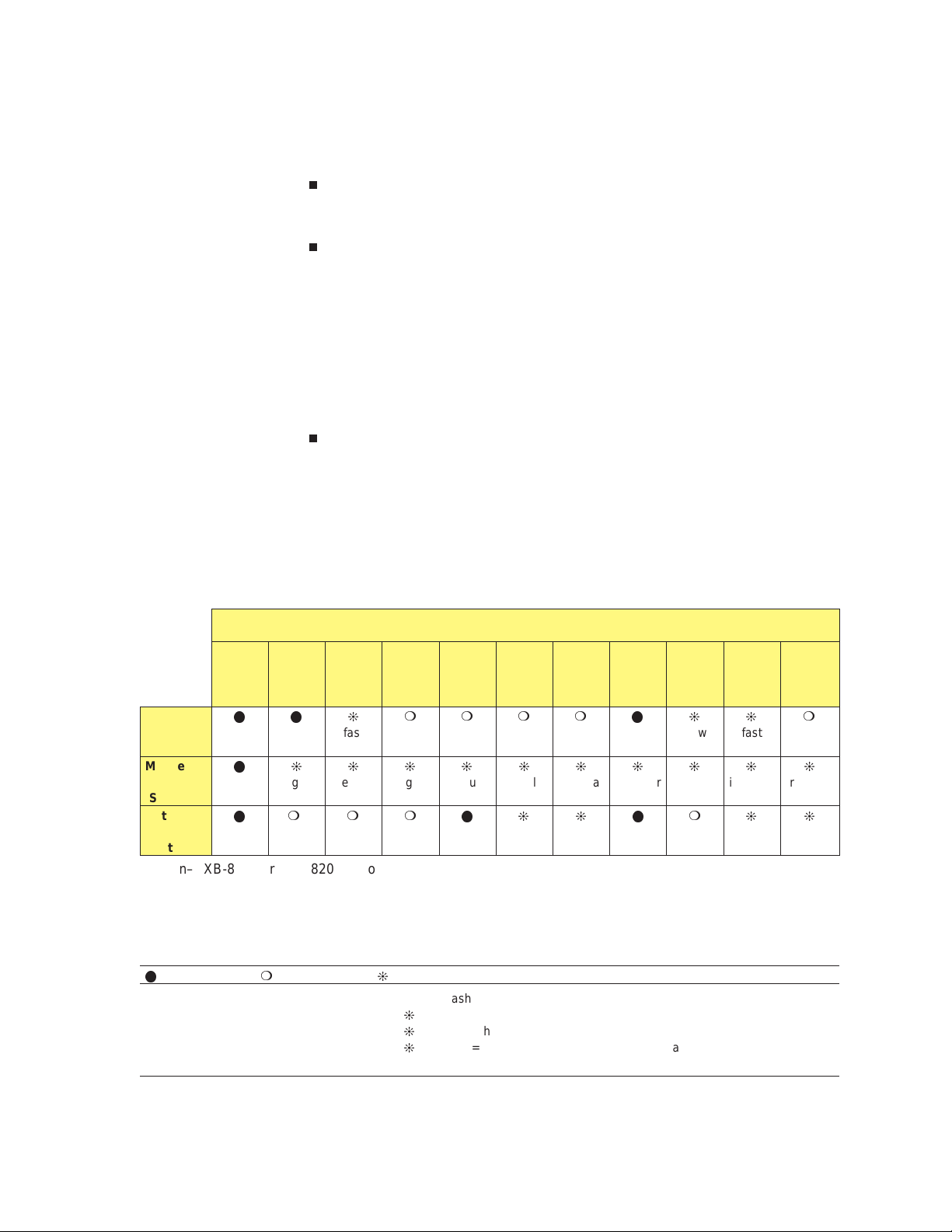
4 Requirements for Use
Different LED combinations indicate the tape drive’s operating state,
as follows:
When the top (amber) LED is on or flashing, the tape drive either
has an error or needs to be cleaned.
When the middle LED is on or flashing, SCSI bus activity is
occurring. The middle LED can be green or amber, as follows:
When this LED is amber, the tape loaded in the tape drive is
•
in compressed format (8500c or 8200c).
When this LED is green, the tape loaded in the tape drive is in
•
uncompressed format (8500 or 8200).
When the bottom (green) LED is on or flashing, tape motion is
occurring.
Table 4-3 shows the various combinations of LEDs that may occur to
indicate different operating states during tape drive operation.
Table 4-3 LED states during operation
Tape Drive State
POST
(1st
part)
Top
LED
(errors)
Middle
LED
(SCSI)
Bottom
LED
(motion)
a
Green–EXB-8500 or EXB-8200 uncompressed format tape.
(green)jirregularjirregularjirregularjirregularjirregularjirregularjirregularjirregularjirregularjirregular
a
POST
(to com-
pletion)
llj
l
lm
Failed
POST
b
Ready–
no tape
loaded
fast
mmlj
Ready–
tape
loaded
mmmmlj
Normal
tape
motion
slow
High-
speed
tape
motion
j
fast
SCSI
bus
reset
lmj
Error Time to
slow
Amber–EXB-8500c or EXB-8200c compressed format tape.
b
If a tape is loaded, the bottom LED will flash slow and then fast during the second part of the power-on self-test.
Key for Table 4-3
lmj
The LED is on. The LED is off. The LED is flashing:
j
slow = 1 flash/second (0.94 Hz)
j
fast = 4 flashes/second (3.76 Hz)
j
irregular = Rate of flash varies with SCSI bus activity. If the tape drive
is not connected to the bus, the LED will be off.
Cleaning
clean
loaded
j
fast
fast
tape
m
j
slow
May 1994 EXB-8205 and EXB-8505 4-13
(Standard and XL)
Page 78

4 Requirements for Use
Loading Data Cartridges
Note: Table 4-3 documents the LED combinations that you are likely
to observe during normal tape drive operation. You may
occasionally observe other LED combinations and sequences.
These other combinations represent special or unusual
conditions that are beyond the scope of this table. (For
example, a fairly complex LED sequence occurs when you
load new microcode from tape.)
To load a tape into the tape drive, first set the write-protect switch on
the EXATAPE data cartridge as required (either write protected or
write enabled), then insert the data cartridge into the tape drive.
Make sure you are using a data cartridge that is compatible with your
tape drive. For information on tape drive and media compatibility,
see Chapter 1.
Important EXATAPE 160m XL media is compatible with the
#
EXB-8205XL and EXB-8505XL only. The EXB-8205 and EXB-8505
will automatically eject these data cartridges. Do not use 160m XL
data cartridges in Exabyte full-high tape drives.
When you insert a cartridge, the tape drive automatically loads the
cartridge, unless the initiator has issued a MODE SELECT (15h)
command to disable the autoload function. Once the data cartridge is
loaded, the tape drive presents ready status (bottom green LED on)
and commands requiring loaded media will execute normally.
Notes: If you disabled the autoload function, the tape drive does
not present ready status until the initiator issues a LOAD
(1Bh) command.
If you attempt to load a cartridge during a power-on
self-test, the tape drive will eject the cartridge.
If you attempt to load a 160m data cartridge that is not
equipped with an Exabyte Recognition System stripe into
an EXB-8205XL or EXB-8505XL, the tape drive will eject the
cartridge.
4-14 EXB-8205 and EXB-8505 510504
(Standard and XL)
Page 79

Load Time
4 Requirements for Use
Refer to EXB-8205 and EXB-8505 Installation and Operation for
instructions for setting the write-protect switch and loading data
cartridges in the tape drive. Refer to the EXB-8205 and EXB-8505 SCSI
Reference for information about the MODE SELECT and LOAD
commands.
Thetimerequiredtoloadthedatacartridgeandpositionthetapeto
LBOT after the data cartridge is inserted is approximately 60 seconds.
When loading a tape, the tape drive spaces forward from PBOT and
determines the following:
Thetapeformat. The format will be either 8200, 8200c, 8500,
8500c, or unknown.
The adaptive servo parameters.This process enables the tape
drive to read tapes produced by different manufacturers, tapes
that are aged and worn, and tapes written by other 8mm tape
drives.
The length of the tape in use. The tape drive autosizes the data
cartridge to determine the tape length. For more information
about autosizing, refer to the EXB-8205 and EXB-8505 SCSI
Reference.
Unloading Data Cartridges
You can unload a data cartridge by either pressing the unload button
or by issuing an UNLOAD (1Bh) command. This section describes
what happens when the unload button is pressed. For information
about using the LOAD/UNLOAD (1Bh) command, see the EXB-8205
and EXB-8505 SCSI Reference.
If a data cartridge is loaded and the tape drive is error free, the tape
drive performs the following actions when you press the unload
button:
Completes any command that is currently in progress
Writes any buffered information to tape
Writes EOD (except in 8200 format)
Rewinds the tape to physical beginning of tape (PBOT)
Unloads the tape from the tape path and ejects the tape
In addition, the tape drive has several unload button options for
“normal,” “fast,” and “super fast” unload operations.
May 1994 EXB-8205 and EXB-8505 4-15
(Standard and XL)
Page 80

4 Requirements for Use
Effect of PREVENT/ALLOW MEDIUM REMOVAL Command
Error During Unload Procedure
If an initiator has issued a PREVENT MEDIUM REMOVAL (1Eh)
command to prevent the removal of the data cartridge, the tape drive
will not eject the data cartridge until the initiator sends an ALLOW
MEDIUM REMOVAL (1Eh) command to allow you to remove the
data cartridge.
For more information about using the PREVENT/ALLOW MEDIUM
REMOVAL command, see the EXB-8205 and EXB-8505 SCSI Reference.
If an error exists before or during the unload procedure, the tape
drive suspends the preceding sequence of events and the top amber
LED will flash. If you press the unload button again, the tape drive
reattempts the unload sequence; however, the tape drive does not
write data in the buffer to tape. The tape drive clears the buffer and
errors.
Resetting the Tape Drive
You can reset the tape drive by any of the following methods:
Powering the tape drive off and back on again (power-on reset).
Sending an RST pulse on the SCSI bus for a minimum of 25 µsec
(SCSI bus or “hard” reset). A SCSI bus reset immediately clears all
devices from the bus and resets their associated equipment.
Issuing a Bus Device Reset (0Ch) message to the tape drive
(device or message reset). A device reset clears the tape drive
from the bus and causes all commands to be cleared.
Pressing the unload button to clear a servo error.
Note: If a SCSI bus or device reset occurs during a power-on reset,
the tape drive will perform a full power-on reset.
If the tape drive has a data cartridge inserted or loaded when a reset
condition occurs, it rewinds the tape and positions to LBOT after the
reset operation is complete. The total time required for the reset may
be as long as three minutes if the tape is positioned near the end of
tape.
4-16 EXB-8205 and EXB-8505 510504
(Standard and XL)
Page 81

Using SCSI Commands
You can use SCSI commands to read, write, erase, and search for data.
You can also copy microcode, inquire about tape drive status, set
operating parameters, and perform diagnostic tests using SCSI
commands.
For information on these commands and how to use them, see
Chapter 5.
Preventive Maintenance
Except for cleaning, the tape drive has no user serviceable
adjustments or maintenance procedures. All service or repairs to the
tape drive must be performed by Exabyte Corporation or authorized
service personnel.
4 Requirements for Use
Cleaning the Tape Drive
The tape drive’s tape heads and tape path should be cleaned on a
regular basis. The only cleaning material authorized for use with the
tape drive is an Exabyte or Exabyte-approved 8mm cleaning cartridge.
To prevent contamination of the tape drive and damage to the
heads, do not attempt to rewind the material in the cleaning
cartridge and reuse it. Discard the cleaning cartridge after you have
used it for the specified number of cleaning cycles.
Using any cleaning cartridges not approved by Exabyte will void
the warranty on the tape drive.
For more information on Exabyte cleaning cartridges, see Chapter 1.
For instructions for using the cleaning cartridge, refer to EXB-8205
and EXB-8505 Installation and Operation.
CAUTION
May 1994 EXB-8205 and EXB-8505 4-17
(Standard and XL)
Page 82

4 Requirements for Use
Determining When the TapeDrive Needs Cleaning
Time-to-Clean LED Indication
You should clean the tape drive’s heads and tape path after every 30
tape motion hours. This cleaning frequency does not depend on the
format in which you write and read data. However, if you are using
the tape drive in a particularly dirty environment or if you operate it
infrequently, you may want to clean it more often than every 30 tape
motion hours. Cleaning the tape drive helps to ensure that it will
perform according to its specifications.
The tape drive keeps track of tape motion hours internally. When 30
tape motion hours have elapsed, the top and bottom LEDs will flash
rapidly and the middle LED will flash irregularly, depending on SCSI
bus activity (see Table 4-3). For best results, clean the tape drive as
soon as possible after the LEDs begin flashing.
REQUEST SENSE (03h) Command
If desired, you can issue a REQUEST SENSE (03h) command and look
at the setting of the CLN and CLND bits (byte 21, bits 4 and 3). If the
CLN bit is set to 1, the tape drive needs to be cleaned. This bit is reset
to 0 when a successful cleaning cycle has been performed. The CLND
bit is set to 1 when the tape drive has been cleaned and is reset to 0
when the next REQUEST SENSE command is received.
Loading New Microcode
To upgrade the microcode in the tape drive, you can:
Use a microcode update tape that you obtain from Exabyte (no
special software required)
Create a microcode update tape from another tape drive using the
Exabyte CTS Monitor program
Use Exabyte microcode update diskettes with CTS Monitor
Copy microcode from the Exabyte Technical Support bulletin
board and load it in your tape drive using CTS Monitor
4-18 EXB-8205 and EXB-8505 510504
(Standard and XL)
Page 83

Use the READ BUFFER command to copy the new code from a
tape drive across the SCSI bus to an initiator. You can then use the
WRITE BUFFER command to copy the code from the initiator to
another tape drive.
For more information about the CTS Monitor program, refer to the
CTS Monitor documentation. For more information about using SCSI
commands, refer to the EXB-8205 and EXB-8505 SCSI Reference.
Shipping Requirements
This section describes the shipping requirements for the tape drive,
including information about the shipping carton and a list of the
environmental conditions needed for transporting the tape drive.
4 Requirements for Use
Shipping Cartons
The tape drive is sealed in a static protection bag and is shipped with
either one drive per carton (single pack) or with three to five drives
per carton (multi-pack).
Table 4-4 shows shipping dimensions and weights for the tape drive.
Table 4-4 Single pack and multi-pack shipping dimensions and weights
Size Dimensions Weight
Single-pack
Multi-pack
13.5 inches long ×
10.75 inches wide ×
8.5 inches high
(34.3 × 27.3 × 21.6 cm)
23.25 inches long ×
13.5 inches wide ×
11.5 inches high
(59.1 × 34.3 × 29.2 cm)
1CTS: 4.5 lbs (2.0 kg)
3CTSs: 12 lbs (5.4 kg)
4CTSs: 15 lbs (6.5 kg)
5CTSs: 18 lbs (8.2 kg)
May 1994 EXB-8205 and EXB-8505 4-19
(Standard and XL)
Page 84

4 Requirements for Use
Both the single-pack and the multi-pack shipping cartons and internal
packing materials are designed so that an enclosed tape drive does
not receive a shock greater than 45 g when the carton is dropped on
any surface, corner, or edge from the following heights:
48 inches (121.9 cm) at a velocity change of 192 inches per second
(488 cm/sec) for the single-pack carton
36 inches (91.4 cm) at a velocity change of 167 inches per second
(424 cm/sec) for the multi-pack carton
Both sizes of shipping carton pass the tests described in the National
Safe Transit Association (NSTA) Project 1A for packaged products
weighing less than 100 pounds.
Note: Do not use a multi-pack shipping carton when shipping a
single tape drive. If you use a multi-pack shipping carton, you
must place three, four, or five tape drives in the carton.
The packing materials are unbleached, reusable, recyclable, and
environmentally safe. The materials contain no chlorofluorocarbons
(CFCs) or heavy metals.
Unpacking and Packing Instructions
Unpacking and packing instructions for the tape drive are included in
EXB-8205 and EXB-8505 8mm Cartridge Tape Subsystem Installation and
Operation.
To avoid damaging the tape drive, use the original shipping carton
and packing materials (or replacement packaging obtained from the
vendor) when repacking and shipping the tape drives. The shipping
carton and packing materials are not intended to be used for shipping
items other than an Exabyte half-high tape drive.
4-20 EXB-8205 and EXB-8505 510504
(Standard and XL)
Page 85

5
Interface Specifications
This chapter describes the tape drive’s SCSI interface, including the
following sections:
SCSI features
Physical path
SCSI messages
SCSI commands
Using SCSI commands
May 1994 EXB-8205and EXB-8505 5-1
(Standard and XL)
Page 86

5 Interface Specifications
SCSI Features
Implementation characteristics of the Small Computer System
Interface (SCSI) controller include the following:
Support for single-ended or differential SCSI configurations.
SCSI bus parity checking configurable through the MODE
SELECT command.
Support for multiple initiator configurations.
Support of the disconnect, reconnect, and arbitration feature,
which releases the tape drive from the bus so that it can operate
under its own internal intelligence system, enabling the SCSI bus
to perform other I/O requests.
The SCSI implemented for the tape drive conforms to the following
standard for a sequential access device: ANSI Small Computer System
Interface-2 (SCSI-2), X3.131-1994.
Data Transfer Rate
The maximum obtainable data transfer rates for the tape drive
depend on what mode it is operating in. For information on data
transfer rates, see Chapter 6.
Physical Path
The physical path implemented by the tape drive includes an
eight-port, daisy-chained bus with the following features:
Single-host or multiple-host computer system capability
Bus contention handled by distributed arbitration on a prioritized
basis
Accommodation of multiple peripheral device types
Multiple overlap of peripheral device operations
Orientation toward intelligent peripheral devices
Enhanced operation with buffered devices
5-2 EXB-8205 and EXB-8505 510504
(Standard and XL)
Page 87

SCSI Messages
The SCSI message system supported by the tape drive allows
communication between the initiator and the tape drive for physical
path management. Table 5-1 lists the SCSI messages supported by the
EXB-8205, EXB-8205XL, EXB-8505, and EXB-8505XL.
RefertotheEXB-8205 and EXB-8505 SCSI Reference for detailed
information about SCSI communications and messages.
Table 5-1 SCSI messages
5 Interface Specifications
Hex Value Description
00h Command Complete
01h Extended Message
(Synchronous Data
Transfer Request)
02h Save Data Pointers
03h Restore Pointers
04h Disconnect
05h Initiator Detected Error
06h Abort
07h Message Reject
08h No Operation
09h Message Parity Error
0Ch Bus Device Reset
In
(Tape drive to
initiator)
4
44
4
4
4
44
Out
(Initiator to
tape drive)
4
4
4
4
4
80h or C0h Identify
44
May 1994 EXB-8205and EXB-8505 5-3
(Standard and XL)
Page 88

5 Interface Specifications
SCSI Commands
The SCSI-2 command set supported by the tape drive consists of 19
six-byte commands (Group 0 command set) and 6 ten-byte
commands (Group 1 command set). These commands are listed in
Table 5-2.
Note: Tapes written and read in 8200 format use the SCSI-1
command set. See the EXB-8205 and EXB-8505 SCSI Reference
for more information.
Table 5-2 SCSI-2 command set
Command OP Code
ERASE 19h Causes the tape drive to erase all tape from the
INQUIRY 12h Requests that information about the tape drive
LOAD/UNLOAD 1Bh Causes the tape drive to load or unload the data
LOCATE 2Bh Allows you to position the tape at a specified logical
LOG SELECT 4Ch Allows you to manage the counters that the tape drive
LOG SENSE 4Dh Allows you to retrieve statistical information about the
MODE SELECT 15h Allows you to specify medium, logical unit, and device
MODE SENSE 1Ah Enables the tape drive to report medium, logical unit,
Description
current tape position to the physical end of tape.
parameters be sent to the initiator.
cartridge.
block address. Used in conjunction with the READ
POSITION command.
maintains about its write and read error recovery
operations.
tape drive’s read and write error recovery operations.
parameters.
or device parameters.
PREVENT/ALLOW MEDIUM
REMOVAL
READ 08h Transfers one or more bytes or blocks of data from the
READ BLOCK LIMITS 05h Requests that the tape drive return data identifying the
1Eh Allows or disallows the removal of the data cartridge
from the tape drive.
tape to the initiator.
maximum and minimum logical block lengths
supported.
5-4 EXB-8205 and EXB-8505 510504
(Standard and XL)
Page 89

5 Interface Specifications
Command OP Code
READ BUFFER 3Ch Copies the tape drive’s microcode across the SCSI
READ POSITION 34h Reports the tape drive’s current logical position but
RECEIVE DIAGNOSTIC
RESULTS
RELEASE UNIT 17h Releases a tape drive from an initiator’s exclusive use,
REQUEST SENSE 03h Requests that the tape drive transfer sense data to the
RESERVE UNIT 16h Reserves the tape drive for an initiator’s exclusive use,
1Ch Reports the results of the tests requested by a
Description
bus to the initiator. Used in conjunction with the
WRITE BUFFER command.
does not cause tape motion to occur. Used in
conjunction with the LOCATE command.
previous SEND DIAGNOSTIC command or to obtain a
trace of SCSI and servo command activity for the tape
drive.
or if third-party reservations are in effect, from another
SCSI device’s use. Used in conjunction with the
RESERVE UNIT command.
initiator.
or if third-party reservations are in effect, for another
SCSI device’s use. Used in conjunction with the
RELEASE UNIT command.
REWIND 01h Causes the tape drive to rewind the tape to the logical
beginning of tape.
SEND DIAGNOSTICS 1Dh Causes the tape drive to perform certain
self-diagnostic tests.
SPACE 11h Enables the tape drive to perform forward or backward
searches.
TEST UNIT READY 00h Allows you to determine if the tape drive is ready to
accept an appropriate medium access command.
VERIFY 13h Enables the tape drive to verify one or more logical
blocks of data on the tape.
WRITE 0Ah Transfers one or more bytes or blocks of data from the
initiator to the tape drive.
WRITE BUFFER 3Bh Allows you to load new microcode from the SCSI bus
into the tape drive’s control memories. Used in
conjunction with the READ BUFFER command.
WRITE FILEMARKS 10h Causes the tape drive to write zero, one, or more
filemarks or setmarks (8500c format) to tape.
May 1994 EXB-8205and EXB-8505 5-5
(Standard and XL)
Page 90

5 Interface Specifications
Using SCSI Commands
This section describes the SCSI commands used to write, read, erase,
and search for data, and to copy microcode, inquire about tape drive
status, set operating parameters, and perform diagnostic tests.
Writing Data
To transfer bytes or blocks of data from the initiator to the tape drive,
use the WRITE (0Ah) command. The data can be written in any of the
four supported logical tape formats (two formats for the EXB-8205
and EXB-8205XL), which are specified by the MODE SELECT (15h)
command.
To write filemarks or setmarks (8500c format only), use the WRITE
FILEMARKS (10h) command.
Reading Data
To transfer bytes or blocks of data from the tape drive to the initiator,
use the READ (08h) command. The tape drive automatically sets itself
to the format used when the tape was written and can read tapes that
have a combination of fixed-length and variable-length blocks.
Erasing Data
Use the ERASE (19h) command to erase all tape from the current
valid tape position to the physical end of tape (PEOT). When the erase
operation is successfully completed, the tape is automatically
rewound to the logical beginning of tape (LBOT).
5-6 EXB-8205 and EXB-8505 510504
(Standard and XL)
Page 91

Searching for Data
To enable the tape drive to perform forward or backward searches,
use the SPACE (11h) or LOCATE (2Bh) commands. The tape drive
moves the tape at its high-speed search speed, which is up to 75 times
the nominal tape speed.
The tape drive can space over both fixed and variable blocks. The tape
drive determines the type of spacing to use according to the type of
block found on the tape.
Copying Microcode
Use the READ BUFFER (3Ch) and the WRITE BUFFER (3Bh)
commands to copy the microcode from one tape drive to another.
5 Interface Specifications
First, issue a READ BUFFER command to place the microcode into
the correct format and to transfer the microcode image across the
SCSI bus to the initiator. Next, issue a WRITE BUFFER command to
transfer the microcode from the initiator to other tape drives.
Inquiring About Tape DriveStatus
To inquire about tape drive status, you can use the commands
described below.
REQUEST SENSE (03h) Command
Use the REQUEST SENSE (03h) command to determine the type of
error when an error occurs or to determine tape drive status. For
errors, this command returns the following information:
Sense Key for the error that indicates the type of error (such as,
Not Ready, Hardware Error, Illegal Request, Unit Attention,
Aborted Command)
Additional Sense Code (ASC) that indicates the type of error for
thegivensensekey
Additional Sense Code Qualifier (ASCQ) that indicates the
specific error for the sense key and ASC
May 1994 EXB-8205and EXB-8505 5-7
(Standard and XL)
Page 92

5 Interface Specifications
INQUIRY (12h) Command
LOG SENSE (4Dh) and LOG SELECT (4Ch) Commands
Performing Diagnostic Tests
Fault Symptom Code (FSC) that indicates the specific nature of
hardware and software errors or other events (the FSC is an
Exabyte-unique byte)
You can use the INQUIRY (12h) command to obtain information
about the tape drive’s firmware level, the version of SCSI supported
by the tape drive, and so on.
You can use the LOG SENSE (4Dh) command to retrieve the tape
drive’s read and write error counters. You can use the LOG SELECT
(4Ch) command to set threshold values for these counters.
You can perform diagnostics to find out detailed information about
tape drive operations. The SEND DIAGNOSTIC (1Dh) command
allows you to run special diagnostic tests, including a drive dump.
The RECEIVE DIAGNOSTIC RESULTS (1Ch) command allows you
to obtain diagnostic results or a dump that provides you with
information about the status of tape drive operations.
Setting Operating Parameters
To set operating parameters for the tape drive, use the MODE
SELECT (15h) command. To find out how the parameters are set for
thetapedrive,usetheMODESENSE(1Ah)command.
5-8 EXB-8205 and EXB-8505 510504
(Standard and XL)
Page 93

Functional
Specifications
6
This chapter includes functional specifications for the tape drive,
including the following sections:
Performance specifications
Reliability specifications
Power specifications
Environmental specifications
May 1994 EXB-8205 and EXB-8505 6-1
(Standard and XL)
Page 94
6 Functional Specifications
Performance Specifications
This section describes the performance specifications for the tape
drive.
Write and Read Access Times
Writeaccesstimestartswhenthetapedrivereceivesthelastbyteof
the WRITE command (that is, when the initiator de-asserts ACK) and
ends when the tape drive asserts REQ to request that the initiator
transfer the first data byte across the SCSI bus.
Read access time starts when the tape drive receives the last byte of
the READ command (that is, when the initiator de-asserts ACK) and
ends when the tape drive asserts REQ to indicate that it is ready to
transfer the first data byte across the SCSI bus to the initiator.
Write and read access times depend on whether the tape drive is
operating in start/stop mode or streaming mode.
Table 6-1 Typical write and read access times
Mode Typical write access
time
Start/stop
Streaming 3.1 msec 3.2 msec
1.7 msec 1.8 msec
Typical read access
time
Note: Themeasurementofwriteaccesstimedoesnotincludethe
initial WRITE command received after the mode is changed
from read to write.
6-2 EXB-8205 and EXB-8505 510504
(Standard and XL)
Page 95
Tape Speed
Table 6-2 lists the nominal tape speed at which data can be written
and read by the tape drives.
Table 6-2 Nominal tape speed
Format Speed
8500c — 11.079 mm/sec (0.436
8500 —
6 Functional Specifications
EXB-8205 and EXB-8205XL EXB-8505 and EXB-8505XL
inch/sec)
8200c
8200
11.079 mm/sec (0.436 inch/sec)
11.633 mm/sec (0.458 inch/sec)
File-Search Tape Speed
Table 6-3 lists forward and backward file-search tape speeds for the
tape drives. These high-speed search times occur when the initiator
issues a LOCATE command (for tapes written in 8200c, 8500, or 8500c
formats) or a SPACE command (for all formats).
Table 6-3 File-search tape speeds
Format Forward Speed Backward Speed
EXB-8205 and
EXB-8205XL
8500c — 831 mm/sec max
8500 — —
EXB-8505 and
EXB-8505XL
(32.7 inch/sec)
EXB-8205 and
EXB-8205XL
— 831 mm/sec max
(32.7 inch/sec)
EXB-8505 and
EXB-8505XL
8200c
8200 116 mm/sec (4.58 inch/sec) 87.25 mm/sec (3.45 inch/sec)
831 mm/sec max (32.7 inch/sec) 831 mm/sec max (32.7 inch/sec)
8500, 8500c, and 8200c Formats
If the tape is written in 8500, 8500c, or 8200c formats, the tape drive
can perform forward and backward file-search operations at up to 75
times the nominal tape speed.
May 1994 EXB-8205 and EXB-8505 6-3
(Standard and XL)
Page 96
6 Functional Specifications
Rewind Tape Speed
8200 Format
If the tape is written in 8200 format, the tape drive can perform
forward file-search operations at 10 times the nominal tape speed and
backward file-search operations at 7.5 times the nominal tape speed.
Table 6-4 lists maximum rewind times for the tape drives for four
sizes of EXATAPE 8mm data cartridges. Rewind time starts when the
initiator issues a REWIND (01h) command and ends when the tape
drive returns a Command Complete message (for a non-immediate
rewind). All times listed in the table assume the following:
The tape is positioned at LEOT when you issue a REWIND
command.
The drum has not stopped rotating.
Tape tension has not been released.
Table 6-4 Typical rewind times
Size of
EXATAPE
15m 15 (49) 50
54m 54 (177) 100
112m 112 (367) 170
160m XL
a
EXATAPE data cartridges are recommended for use with all Exabyte products and
are available for purchase from Exabyte Corporation.
b
160m XL media is intended for use in the EXB-8205XL and EXB-8505XL only.
Reposition Time
Reposition time starts when the initiator issues a command that stops
the tape drive’s motion control system and ends when the tape is
repositioned, at nominal speed, so that the next byte of data can be
transferred. Reposition time is independent of any interface delays.
a
b
Length
m (ft)
160 (524) 240
Typical rewind time
(seconds)
Reposition time for the tape drive ranges from 1.2 sec to 1.5 sec.
6-4 EXB-8205 and EXB-8505 510504
(Standard and XL)
Page 97

Drum Rotation Period
Table 6-5 shows the drum rotation period for the tape drives reading
and writing tapes in all formats.
Table 6-5 Drum rotation periods
Format Drum rotation period Nominal effective
8500c*
8500*
8200c
32.77 msec
(1831.055 rpm)
6 Functional Specifications
head-to-tape speed
3.824 m/sec
(150.548 inch/sec)
8200 31.21 msec
(1922.607 rpm)
*EXB-8505 and EXB-8505XL only
4.015 m/sec
(158.075 inch/sec)
Tape Tension Release and Drum Motion Suspension
The tape drive releases tape tension under either of the following
conditions:
The tape is at LBOT and the tape drive has not received a
command to move the tape in the last 5 seconds.
The tape is not at LBOT and the tape drive has not received a
command to move the tape in the last 15 seconds.
After releasing tape tension, the tape drive will stop drum rotation if
it does not receive a tape motion command within the next 60 seconds.
If tape tension has been released, approximately 1.5 seconds will
elapse before the tape drive can perform a tape motion command. If
the drum rotation has been stopped, approximately 7 seconds will
elapse before the tape drive can perform a tape motion command.
May 1994 EXB-8205 and EXB-8505 6-5
(Standard and XL)
Page 98

6 Functional Specifications
Data Transfer Rate
The maximum obtainable data transfer rates for the tape drive
depend on what mode it is operating in. Table 6-6 shows the data
transfer rates for each of the four formats.
Table 6-6 Data transfer rates
Type of
transfer
Sustained
transfer rate
Synchronous
burst
Asynchronous
burst
a
EXB-8505 and EXB-8505XL only
b
Assumes a 2:1 compression ratio
8500c
up to 1
MBytes/sec
Notes: When compression is enabled, the tape drive can increase
Rate achieved for these formats . . .
a
b
KBytes/sec
a
8500
up to 500
up to 5.0 MBytes/sec
up to 2.5 MBytes/sec
8200c 8200
up to 500
KBytes/sec
b
up to 262.5
KBytes/sec
the sustained transfer rate of up to five times. Compression
throughput and capacity ratios depend on the type of data.
The maximum burst data transfer rate is limited by the
performance of the SCSI host bus adapter, the SCSI bus
interface controller, and the tape drive’s buffer control
hardware.
Reselection Phase Timeout
If the initiator fails to respond to a device reselection sequence, the
tape drive times out after 250 msec. The tape drive continues to repeat
the reselection process until it is reset or the initiator finally responds.
6-6 EXB-8205 and EXB-8505 510504
(Standard and XL)
Page 99

Reliability Specifications
This section lists the reliability specifications for the tape drive.
Service Life
The tape drive has been designed to exceed a useful service life of five
years, during which time all performance and reliability specifications
are applicable.
Machine Reliability: Mean Time Between Failures (MTBF)
6 Functional Specifications
The mean time between failures (MTBF) value for the EXB-8205,
EXB-8205XL, EXB-8505, and EXB-8505XL is 160,000 power-on hours.
The MTBF value for the tape drive is defined as follows:
MTBF =
Number of Relevant Equipment Failures
where:
Total Power-on Hours is the total time the tape drive is drawing
current from the input power supply system.
Relevant Equipment Failures are those failures that cannot be
corrected by the operating personnel and require the intervention
of maintenance personnel.
Total Power-on Hours
May 1994 EXB-8205 and EXB-8505 6-7
(Standard and XL)
Page 100

6 Functional Specifications
Test Conditions
The MTBF value for the tape drive is determined under the following
conditions:
MTBF is specified for a maximum duty cycle of 10%, where duty
cycle is defined as:
Duty Cycle =
The tape drives are tested at the following ambient temperature
and relative humidity:
23° C ± 2° C
•
50% relative humidity ± 10% (non-condensing)
•
The tape drives are operated in accordance with operating
specifications.
Conditions for the MTBF Value
Conditions under which the specifications for MTBF apply are as
follows:
The EXATAPE data cartridges used must comply with Standard
ECMA-145.
Environmental conditions for the tape drive and the 8mm data
cartridges must be maintained as specified in the “Environmental
Specifications” section of this chapter.
Total Hours of Mechanical Operation
100%
Total Power-on Hours
The tape drive must be cleaned with an Exabyte or an
Exabyte-approved cleaning cartridge using the recommended
cleaning procedure. Refer to EXB-8205 and EXB-8505 Installation
and Operation for instructions.
6-8 EXB-8205 and EXB-8505 510504
(Standard and XL)
 Loading...