

Page 1

([DE\WHDQG([DE\WH/LEUDULHV
,QVWDOODWLRQDQG
2SHUDWLRQ
302539-005
Page 2

Copyright
Copyright 1994 – 1999 by Exabyte Corporation. Al l rights reserved. This item and
the information contained herein are the property of Exabyte Corporation. No
part of this document may be reproduced, transmitted, transcribed, stored in a
retrieval system, or translated into any language or computer language in any
form or by any means, electronic, mechanical, magnetic, optical, chemical,
manual, or otherwise, without the express written permission of Exabyte
Corporation, 1685 38th Street, Boulder, Colorado 80301.
Disc l aimer
Exabyte Corporation makes no representation or warranties with respect to the
contents of this document and specifically disclaims any implied warranties of
merchant ability or fitness for any particular purpose. Further, Exabyte
Corporation reserves the right to revise this publication without obligation of
Exabyte Corporation to notify any person or organization of such revision or
changes.
Trademark Notices
Exabyte, Exafacts, Exapak, Exasoft, Exatape, and Strategex are registered
trademarks of Exabyte Corporation. Arrowhead, Eliant, and SupportSuite are
trademarks of Exabyte Corporation. A ll other product names are trademarks or
registered trademarks of their respective owners.
Note: The most current information about this product is available at
Exabyte’s web site (www.exabyte.com).
Exabyte Corporation
1685 38th Street
Boulder, Colorado 80301
302539-005
ii
Exabyte 440 and Exabyte 480
Page 3
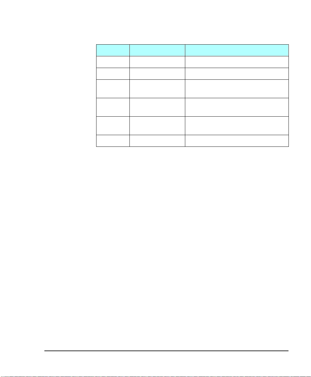
Revision History
Revis ion Date Description
000 July 1994 Beta
001 October 1994 Initial rele ase
002 February 1996 Beta for the Exabyte Mammoth tape
003 March 1996 Initial release for Exabyte Mammoth
004 July 1997 Exabyte 440 and Exabyte 480 su pport
005 June 1999 Added LVD SCSI information
Revisions to This Manual
This revision of Exabyte 440 and Exabyte 480 Libraries Instal lation and Operation (005)
contains the following changes and enhancements:
• Added low-voltage differential (LVD) SCSI information.
• Removed information about the Exabyte 8505 tape drive.
drive
tape drive
for Eliant 820 tape drive
• Added BSMI information.
• Rearra ng e d t he chapters.
Installation and Operation
iii
Page 4

Safety Agency Standards
The Exabyte 440 and Exabyte 480 comply with the following domestic and
international pr oduct safety standards:
• UL Standard 1950, 3rd Edition, Information Technology Equipment
Including Electrical Business Equipment
• CSA Standard C22.2 No. 950-95, Safety of Information Technology
Equipment Including Electr ical Business Equipment
• IEC 950/EN60950, Safety of Information Technology Equipment
including Electrical Business Equipment
FCC Notice
This equipment has been tested and found to comply with the limits for a Class A
digital device, pursuant to part 15 of the FCC Rules. These limits are designed to
prov ide rea sonabl e protect ion agai nst harm ful i nterferenc e when the equipm ent
is o perated in a c o mmerc ial environment. This equip ment generates, uses, and
can radiate radio frequency energy and, if not installed and used in accordance
with this instruction manual, may cause harmful interference to radio
communicatio ns. Operation o f this equipment in a residential area is likely to
caus e har mf ul i nter fer ence i n whi ch ca s e the user wi l l b e req ui r ed to c orr ect the
interference at his own expense.
Shielded cables are required for this device to comply with FCC Rules. Use
shielded cables when connec ting this device to others.
According to FCC regula tions, changes o r modifi c ations to this equi p m ent that
are not expressly approved b y Exabyte could voi d the user’s authority to operate
the equipment.
Industry Canadian Notice per ICES-003
English This Class A digi tal apparatus meets all requirements of the Canadian
Interference-Causing Equipment Regulations.
French Cet appareil numérique de la classe A respecte toutes les exigences du
Règlement sur le matériel brouilleur du Canada.
iv
Exabyte 440 and Exabyte 480
Page 5

European Notice
This eq u i p me nt has been tes t ed a nd c om p lies with the follow ing req uirement s :
EN 55022/CISPR 22, Class A
EN 50082-1: 1992
Bureau of Standards, Metrology, and Inspection (BSMI) – Taiwan
This equipment has been tested and complies with CNS C6357.
Englis h Warning! This is a Class A product. In a domestic environment, this
prod u ct may cause radio interf e rence, i n w hich case, the us er may be required
to take adequate measures.
Australia/New Zealand
This equipment has been tested and complies with AS/NZS 3548.
Installation and Operation
v
Page 6

Product Warranty Caution
The Exabyte® 440 and Exabyte 480 Libraries are warranted to be free from defects
in materials, parts, and workmanship and will conform to the current product
specification upon delivery. For the specific details of your warranty, refer to
your sales contract or contact the company from which the library was
purchased.
The warranty for the library shall not apply to failures of any unit when:
• The l ib ra ry is r epai red by anyone o ther t han Ex aby te’ s per so nnel or
appr o ved ag ent.
• The library is physically abused or is used in a manner that is
inconsistent with the operating instructions or product specification
defined by Exabyte.
• The library fails because of accident, misuse, abuse, neglect,
mishandling, misapplication, alteration, faulty installation,
modification, or service by anyone other than the factory service
center or its approved agent.
• The library is repaired by anyone, including an approved agent, in
a manner that is contrary to the maintenance or installation
instructions supplied by Exabyte.
• Exabyte’s serial number tag is removed.
• The libra ry i s da maged because of improper packaging on return.
vi
CAUTION
R eturning the libra ry in unauthoriz ed pack aging may da mage
the unit and void the warranty.
If problems with the library occur, contact your maintena nce
organization; do not void the product warranty by allowing
untrained or unauthorized personnel to attempt repairs.
Exabyte 440 and Exabyte 480
Page 7

Contents
About this manual . . . . . . . . . . . . . . . . . . . . . . . . . . . . . . . . . . . . . . . . xi
1 Welcome . . . . . . . . . . . . . . . . . . . . . . . . . . . . . . . . . . . . . . . . . . . . . 1
About the Exabyte 440 and Exabyte 480. . . . . . . . . . . . . . . . . . . . . . . . . . 2
Contacting Exabyte . . . . . . . . . . . . . . . . . . . . . . . . . . . . . . . . . . . . . . . . . . 10
2 Hardware Installation. . . . . . . . . . . . . . . . . . . . . . . . . . . . . . . . . . 11
Preparing for installation. . . . . . . . . . . . . . . . . . . . . . . . . . . . . . . . . . . . . . 11
Installing the library hardware. . . . . . . . . . . . . . . . . . . . . . . . . . . . . . . . . 16
3 Configuration . . . . . . . . . . . . . . . . . . . . . . . . . . . . . . . . . . . . . . . . 45
Using the operator panel. . . . . . . . . . . . . . . . . . . . . . . . . . . . . . . . . . . . . . 46
Displaying the Configuration Menu . . . . . . . . . . . . . . . . . . . . . . . . . . . . 51
Setting the SCSI IDs . . . . . . . . . . . . . . . . . . . . . . . . . . . . . . . . . . . . . . . . . . 52
Setting the remaining configuration options . . . . . . . . . . . . . . . . . . . . . 54
Setting robot control modes . . . . . . . . . . . . . . . . . . . . . . . . . . . . . . . . . . . 67
Checking the setup. . . . . . . . . . . . . . . . . . . . . . . . . . . . . . . . . . . . . . . . . . . 70
4 Library Operation . . . . . . . . . . . . . . . . . . . . . . . . . . . . . . . . . . . . . 7 1
Selecting and replacing data cartridges . . . . . . . . . . . . . . . . . . . . . . . . . 71
Replacing the cartridge magazines . . . . . . . . . . . . . . . . . . . . . . . . . . . . . 79
Resetting the library. . . . . . . . . . . . . . . . . . . . . . . . . . . . . . . . . . . . . . . . . . 82
5 Tape Drive Operation . . . . . . . . . . . . . . . . . . . . . . . . . . . . . . . . . . 83
Monitoring the tape drive LEDs. . . . . . . . . . . . . . . . . . . . . . . . . . . . . . . . 84
Cleaning the tape drives . . . . . . . . . . . . . . . . . . . . . . . . . . . . . . . . . . . . . . 85
Displaying information about tape drives . . . . . . . . . . . . . . . . . . . . . . . 89
Ejecting a cartridge manually. . . . . . . . . . . . . . . . . . . . . . . . . . . . . . . . . . 92
Installation and Operation
vii
Page 8

6 Library Information . . . . . . . . . . . . . . . . . . . . . . . . . . . . . . . . . . . 95
Viewing SCSI data. . . . . . . . . . . . . . . . . . . . . . . . . . . . . . . . . . . . . . . . . . . . 96
Viewing statistics. . . . . . . . . . . . . . . . . . . . . . . . . . . . . . . . . . . . . . . . . . . . 102
Viewing system sensors . . . . . . . . . . . . . . . . . . . . . . . . . . . . . . . . . . . . . . 104
Viewing command history. . . . . . . . . . . . . . . . . . . . . . . . . . . . . . . . . . . . 106
Viewing inventory information. . . . . . . . . . . . . . . . . . . . . . . . . . . . . . . . 108
7 Hardware Exercises. . . . . . . . . . . . . . . . . . . . . . . . . . . . . . . . . . 115
Performing diagnostics. . . . . . . . . . . . . . . . . . . . . . . . . . . . . . . . . . . . . . . 115
Configuring the serial ports for diagnostics . . . . . . . . . . . . . . . . . . . . . 124
8 Troubleshooting . . . . . . . . . . . . . . . . . . . . . . . . . . . . . . . . . . . . 127
Problems with library installation. . . . . . . . . . . . . . . . . . . . . . . . . . . . . . 128
Problems with tape drive operation. . . . . . . . . . . . . . . . . . . . . . . . . . . . 130
Problems with library operation. . . . . . . . . . . . . . . . . . . . . . . . . . . . . . . 131
If you cannot resolve the problem... . . . . . . . . . . . . . . . . . . . . . . . . . . . . 132
9 Maintenance. . . . . . . . . . . . . . . . . . . . . . . . . . . . . . . . . . . . . . . . 133
Cleaning the front window . . . . . . . . . . . . . . . . . . . . . . . . . . . . . . . . . . . 134
Using touch-up paint on the housing. . . . . . . . . . . . . . . . . . . . . . . . . . . 134
Replacing the fuse . . . . . . . . . . . . . . . . . . . . . . . . . . . . . . . . . . . . . . . . . . . 135
Replacing the air filter. . . . . . . . . . . . . . . . . . . . . . . . . . . . . . . . . . . . . . . . 137
Replacing a tape drive (or drive blank) . . . . . . . . . . . . . . . . . . . . . . . . . 140
A Specifications. . . . . . . . . . . . . . . . . . . . . . . . . . . . . . . . . . . . . . . 145
Storage capacity. . . . . . . . . . . . . . . . . . . . . . . . . . . . . . . . . . . . . . . . . . . . . 145
Operating environment . . . . . . . . . . . . . . . . . . . . . . . . . . . . . . . . . . . . . . 146
Size and weight . . . . . . . . . . . . . . . . . . . . . . . . . . . . . . . . . . . . . . . . . . . . . 146
Power. . . . . . . . . . . . . . . . . . . . . . . . . . . . . . . . . . . . . . . . . . . . . . . . . . . . . . 147
Power cord requirements. . . . . . . . . . . . . . . . . . . . . . . . . . . . . . . . . . . . . 147
SCSI terminator specifications. . . . . . . . . . . . . . . . . . . . . . . . . . . . . . . . . 148
SCSI cable specifications. . . . . . . . . . . . . . . . . . . . . . . . . . . . . . . . . . . . . . 149
Remote reset cable specifications . . . . . . . . . . . . . . . . . . . . . . . . . . . . . . 151
viii
Exabyte 440 and Exabyte 480
Page 9

B SCSI Basics . . . . . . . . . . . . . . . . . . . . . . . . . . . . . . . . . . . . . . . . . 153
SCSI components . . . . . . . . . . . . . . . . . . . . . . . . . . . . . . . . . . . . . . . . . . . 153
Considerations for installing the library on the SCSI bus . . . . . . . . . 154
C LCD Error Codes. . . . . . . . . . . . . . . . . . . . . . . . . . . . . . . . . . . . . 159
D Library Elements. . . . . . . . . . . . . . . . . . . . . . . . . . . . . . . . . . . . . 169
E Packing and Shipping the Library . . . . . . . . . . . . . . . . . . . . . . . 173
Returning the library for service . . . . . . . . . . . . . . . . . . . . . . . . . . . . . . 173
Packing the library . . . . . . . . . . . . . . . . . . . . . . . . . . . . . . . . . . . . . . . . . . 174
Index . . . . . . . . . . . . . . . . . . . . . . . . . . . . . . . . . . . . . . . . . . . . . . . . . . .187
Installation and Operation
ix
Page 10

Notes
x
Exabyte 440 and Exabyte 480
Page 11

About this manual
Use this manual to install, configure, operate, maintain, and
diagnose problems with your library.
Conventions used in this manual
This manual uses the following conventions:
>(QWHU@ Boxed text indicates keys on the operator panel.
Note: Notes provide hints or suggestions about the topic
or procedure being discussed.
➤ Important Information next to the heading
“Importan t” he lps you complete a procedure or
avoid extra steps.
Installation and Operation
CAUTION
Boxed text under the head ing “ CAUTION”
provides information you must know to avoid
damaging the library or tape drives or losing
data.
xi
Page 12

:$51,1*
Boxed text under the heading “WARNING!”
provides information you must know to avoid
per sonal in jury.
Related publications
For informati on about these libr aries, the tape drives, and the
standards used by these libraries, refer to the following
publications.
Note: Exabyte technical p ublications are ava ilable on the
Support Services section of the Exabyte web site
(www.exabyte.com).
Exabyt e 440 and Exabyte 480 libraries
Exabyte 440 and Exabyte 480 8mm Libraries Product
Specification, 302538
xii
EXB-440 and EXB-480 8mm Libraries SCSI Reference,
302541
Exabyte 440 and Exabyte 480 8mm Libraries Maintenance,
302542
Exabyte 440 and Exabyte 480 8mm Libraries Planning for
Integration, 302543
Exabyte 440 and Exabyte 480 Illustrated Parts Catalog, 302544
Exabyte Bar Code Label Specification for 8mm Cartridges,
308607
Exabyte 440 and Exabyte 480
Page 13

Exabyte Mammoth 8mm tape drive
Exabyte Mammoth Product Specification, 306482
Exabyte Mammoth SCSI Reference, 306483
Exabyte Mammoth Installation and Operation, 306484
Eliant 820 8mm tape drive
Exabyte Eliant 820 Product Specification, 316593
Exabyte Eliant 820 SCSI Reference, 316869
Exabyte Eliant 820 Installation and Operation, 317209
Standards
ANSI Small Computer System Interface-2 (SCSI-2),
Z3.131-1994
ANSI Small Computer System Parallel Interface-2, X3T10/
1142D
Installation and Operation
xiii
Page 14

Notes
xiv
Exabyte 440 and Exabyte 480
Page 15
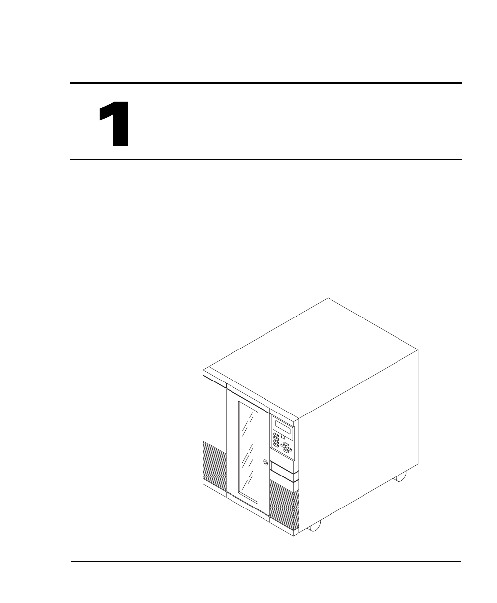
1Welcome
Congratulations on selecti ng the Exabyte 440 or Exabyte 480
Library (EXB-440 or EXB-480). You r new library provides
automated data storage, archiving, backup, and retrieval for
mid-range and high-end workstations, servers, and
networks.
Installation and Operation
1
Page 16

Chapter 1
The library’s robotic cartridge handling mechanism (CHM)
responds to commands from the host application to move
data cartr idg es between tape drives and s torag e sl ots, whi le
the tape drives read and write data. You can insert and
remove cartridges through the entry/exit port wi thout
opening the library door.
Abou t the Exabyte 440 and Exabyte 480
The following illustrations and descriptions summarize the
important library features. For library specifications, refer to
the Exabyte 440 and Exabyte 480 8mm Libraries Product
Specification.
The Exabyte 440 contains 40 data cartridge slots, while the
Exabyte 480 contains 80 data cartridge slots. Both libraries can
contain up to four Exabyte Mammoth tape drives or four
Eliant 820 tape drives.
The library is av ailable in narrow or wide, single-ended,
low-voltage differential (L VD), or high-voltage differ ential
(HVD) SCSI configurations. The narrow SCSI lib r a r y
contains either Mammoth or Eliant 820 tape drives and
operates on up to four SCSI buses. The wide SCSI library
contains Mammoth tape drives only and operates on up to
five SCSI buses.
2
Exabyte 440 and Exabyte 480
Page 17
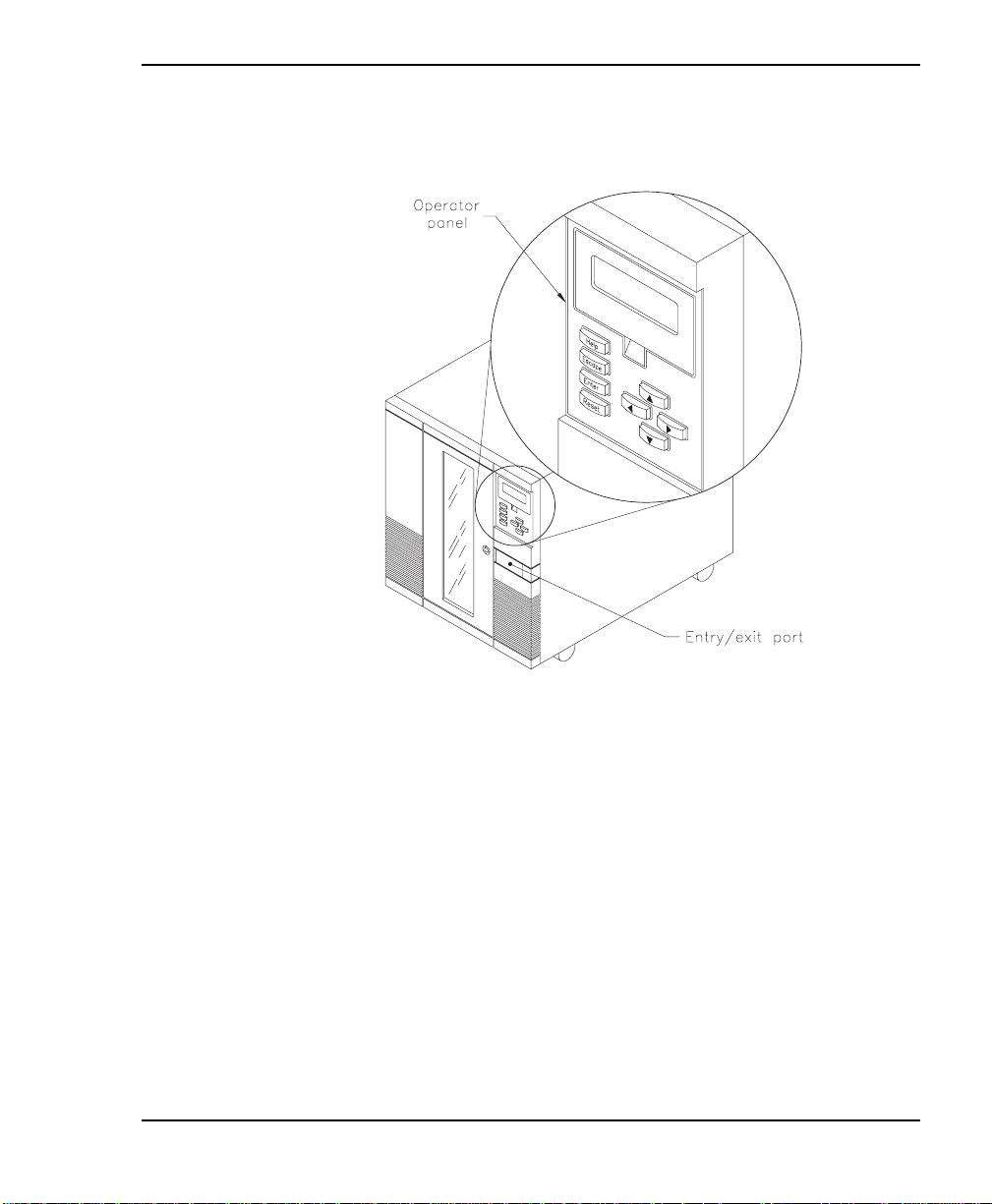
Front panel components
Welcome
Operator panel
The operator panel includes a four-line liquid crystal display
(LCD) and a keypad. Use the operator panel to access menu
options used to configure the librar y and monitor operations.
If necessary, you can tilt the LCD for easier viewing.
Entry/ exit port
The entry /exit port allows you to insert or remove individual
cartridges from the library without opening the door.
Installation and Operation
3
Page 18
Chapter 1
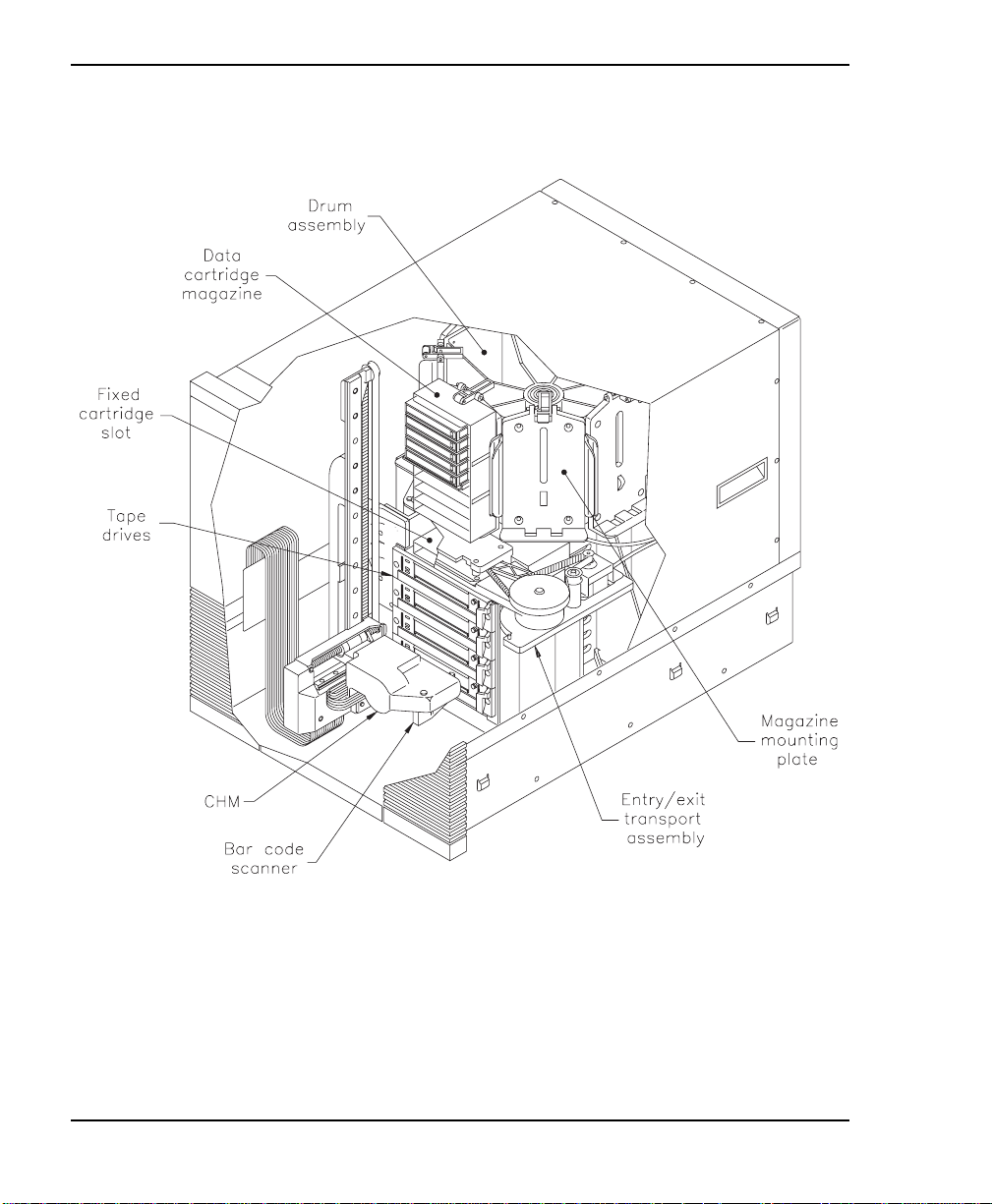
Internal components
Drum assembly
The drum assembly holds the data cartr idge ma gazines and
rotates 180 degrees in either direction to position the
magazines in front of the CHM.
4
Exabyte 440 and Exabyte 480
Page 19

Welcome
Data cart ridge magazines
Data ca rtridge ma gazines ar e t he remo vable car rier s f o r the
data cartridges. The magazines snap onto mounting plates
on the library’s rotating drum assembly and allo w easy
removal an d replacement of cartridges. Eac h magazin e has
individual cartridge slots for ten 8mm cartridges. The
Exabyte 440 cont ains up to four data cartridge magazines;
the Exabyte 480 contains up to eight.
Fixed cartridge s lot
The fixed cartridge slot, located directly above the tape
drives, allows you to store an 8mm c leaning cartrid g e or an
additional 8mm data cartridge.
Tape drives
The library can accommod ate up to four of the following
8mm tape drives:
Mammoth with a wide SCSI configuration
Mammoth with a narrow SCSI c onfiguratio n
Eliant 820 with a narrow SCSI configuration
➤ Important Y ou cannot combine Exabyte
Installation and Operation
Mammoth ta pe dri ves with a ny other type of ta pe
drive in the same library.
5
Page 20
Chapter 1
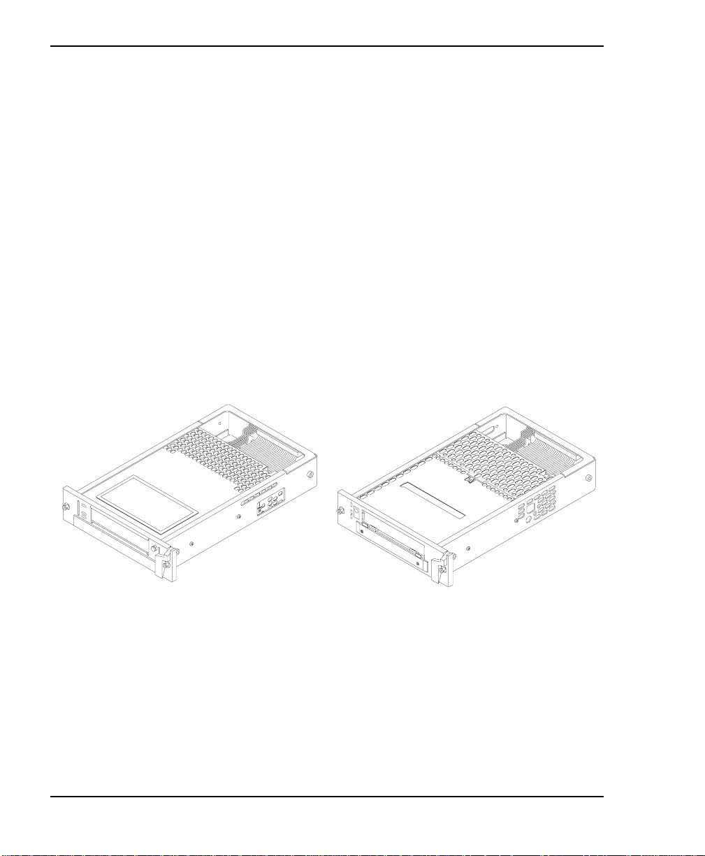
Drive carrier When you purchase the library, each tape
drive in the library is fitted in side a d rive carrier. The drive
carrier allows you to slide the drive in and out of the library
if the tape drive needs repair or if you are adding new tape
drives.
Because the tape drives have different faceplates, there are
different drive carr iers for Mammoth tape drives and
Eliant 820 tape drives, as shown below. Because of the
different SCSI c onnectors, there is a third drive carrier for
Mammoth wide SCSI tape drives (not shown).
Note: You must purchase the tape drive pre-installed in
the drive carrier.
Mammoth drive carrier Eliant 820 drive carrier
6
Exabyte 440 and Exabyte 480
Page 21

Welcome
Drive blank Drive blanks are “empty” drive carriers with
solid faceplates. If you plan to operate the library with fewer
than four tape drives, you must install drive blanks in the
emp ty drive positions. The drive blanks ensure correct
airflow through the library for cooling, compliance with EMI
regu lations, and in some configurations, correct SCSI
conn e ct ion .
There are two types of drive blanks to match the different
SCSI configurations: wide SCSI and narrow SCSI.
Cartridge handling mechanism (CHM)
The cartridge handling mechanism (CHM) moves cartridges
between cartridge slots, tape drives, and the entry/exit port.
Bar code scanner
The high-speed bar code scanner, mounted on the CHM,
reads bar code labels affixed to the cartridges to track
individual cartridges. Cartridge label information becomes
part of the library’s cartridge inventory stored in nonvolatile
RA M.
Entry/ exit tra nsport assembly
The entry/exit transport assembly moves the transport arm
to and from the entry/exit port to pick up cartridges.
Installation and Operation
7
Page 22
Chapter 1
Serial ports
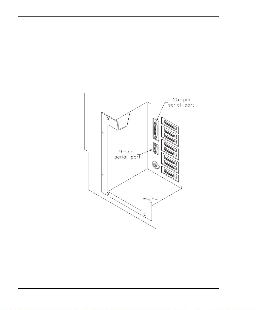
Two serial ports (25-pin and 9-pin) at the back of the library
allow you to communicate with the tape drives and the
library across a serial cable connected to an external
computer. By running a special diagnostic program, you can
perform diagnostics, upgrade firmware, and test CHM
motion.
8
Exabyte 440 and Exabyte 480
Page 23
Welcome
SCSI connectors
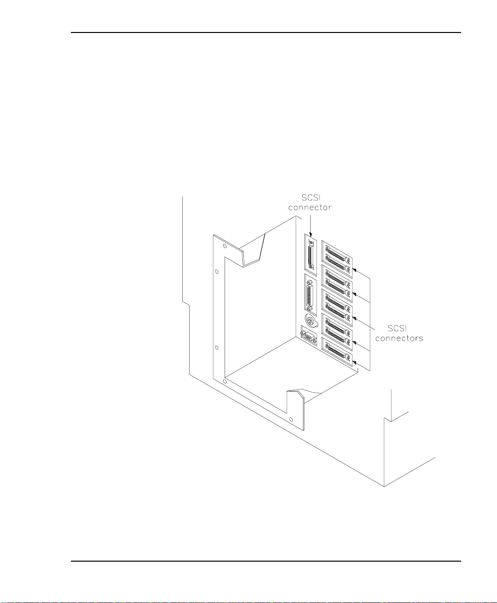
The li brary has eit her eight or t en SCSI connector s, acc essib le
through the cabling bay on the back. Narrow SCSI libraries
have eight connectors and can be connected to up to four
SCSI buses (the tape drive in the uppermost slot and the
library are on the same bus). Wide SCSI libraries have ten
connectors and can be attached to up to five SCSI buses (all
four tape drives and the library can be on separate buses).
Installation and Operation
9
Page 24
Chapter 1
Cont acting Exabyte
To obtain technical support
Exabyte Technical Support 1-800-445-7736
e-mail [email protected]
World Wide Web http://w w w .exabyte.com
To order supplies and accessories
Exabyte Express 1-800-EXATAPE
To ret urn equipment for service
1-303-417-7792
1-303-417-7160 (fax)
(1-800-392-8273)
1-972-481-4221
1-972-406-9081 (fax)
10
Exabyte Service 1-800-EXATAPE
(1-800-392-8273)
Scotland: + 44-1324-564564
e-mail [email protected]
Note: If it is more convenient to your location, contact
Exabyte Technical Support in Europe at the
fo llowi ng nu mbers:
Phone: + 31-30-254-8890
Fax: + 31-30-258-1582
BBS: + 31-30-258-1617
Exabyte 440 and Exabyte 480
Page 25
2Hardware Installation
This chapter describes how to install and set up the library
hardware.
Preparing for installation
Before insta lling the library, complete the following preliminary
steps.
Step Description
✔
1 Unpack the library.
2 Obtain accessories and equipment.
3 Prepare the host computer.
Step 1 – Unpack the library
Complete the unpacking steps printed on the box. Save all original
pack ing materials in case you ne ed to ship or move the library
late r.
Installation and Operation
4 Prepare the library for installation.
11
Page 26

Chapter 2
Step 2 – Obtain accessories and equipment
Make certain you have all the accessories and equipment for
library operation, as indicated in the table below. Many of these
items are included in the library accessories box (a separate box at
the top of the carton).
Required accessories and equipment
Power cord Included with the library.
(Page 147 provides power cord
spec ific ations for other voltage s
and international use.)
Two keys for the front door Included with the library.
Jumpers for connecting the
libra ry and ta pe driv es to a singl e
SCSI bus.
Twelve s cre ws a nd ten c lip nuts
(see page 17 for specific sizes)
Two slide rails
SCSI cables If these items are not included
SCSI terminator (s) (require d if
the library or one of the tape
drives is the last device on the
bus)
Data cartridges and cleaning
cartridges
Included with the library (three
for narrow SC SI libra ries a nd four
for wide SCSI libraries).
Included with rack-mount
libraries.
with the l ibr a ry, con tac t Exabyte
to purchas e them. I f you want to
use your own, see page 148 for
specifications. Visit the Exabyte
web site ( www.exa byte.com) for
a list of approved vendors.
If cartridges are not included with
the library, contact Exabyte to
purchase them. If you want to
use your own, refer to page71
for appropriate data cartridges
and to page85 for appropriate
cleaning cartridges.
12
Exabyte 440 and Exabyte 480
Page 27

Hardware Installation
➤ Important Your l ibrary has been shipped to
you with the ta pe drives pre- ins ta l le d. For librarie s
that will operate with fewer than four tape drives,
drive blanks have been installed in the unused
carrier slots. For more information, see “Using
drive blanks” on page140.
Step 3 – Prepare the host comput er
Make sure your SCSI host bus adapter card or cards installed in
the host computer and its application software are compatible
with your library and the tape drives you are using. You can
obtain software compatibility information for Exabyte products
from Exabyte’s web site (www.exabyte.com).
You can install the software application on the host computer
before or after library installation. However , if you install the
software first, you may need to reconfigure it for use with the
library.
Installation and Operation
13
Page 28

Chapter 2
Step 4 – Prepare the library for installation
Prepare the library as follows:
Ensure that the wor k area is free from condit ions that could
caus e elect rosta tic d isc harge ( ESD). Disc harge s tati c elect ric ity
from your body by touching a known grounded surface, such
as your computer’s metal chassis.
Locate an appropriate area for the library. The library must
have a level surface nea r a readily accessible outlet. In
addition, there must be approximately 6 inches (15 cm) of
open area be hind the library for adequate air flow.
If you have a rack-mount library, make sure that your rack has
extension support legs a nd that you have at least four people
or two people and a small fork lif t to lift the library into the
rack.
14
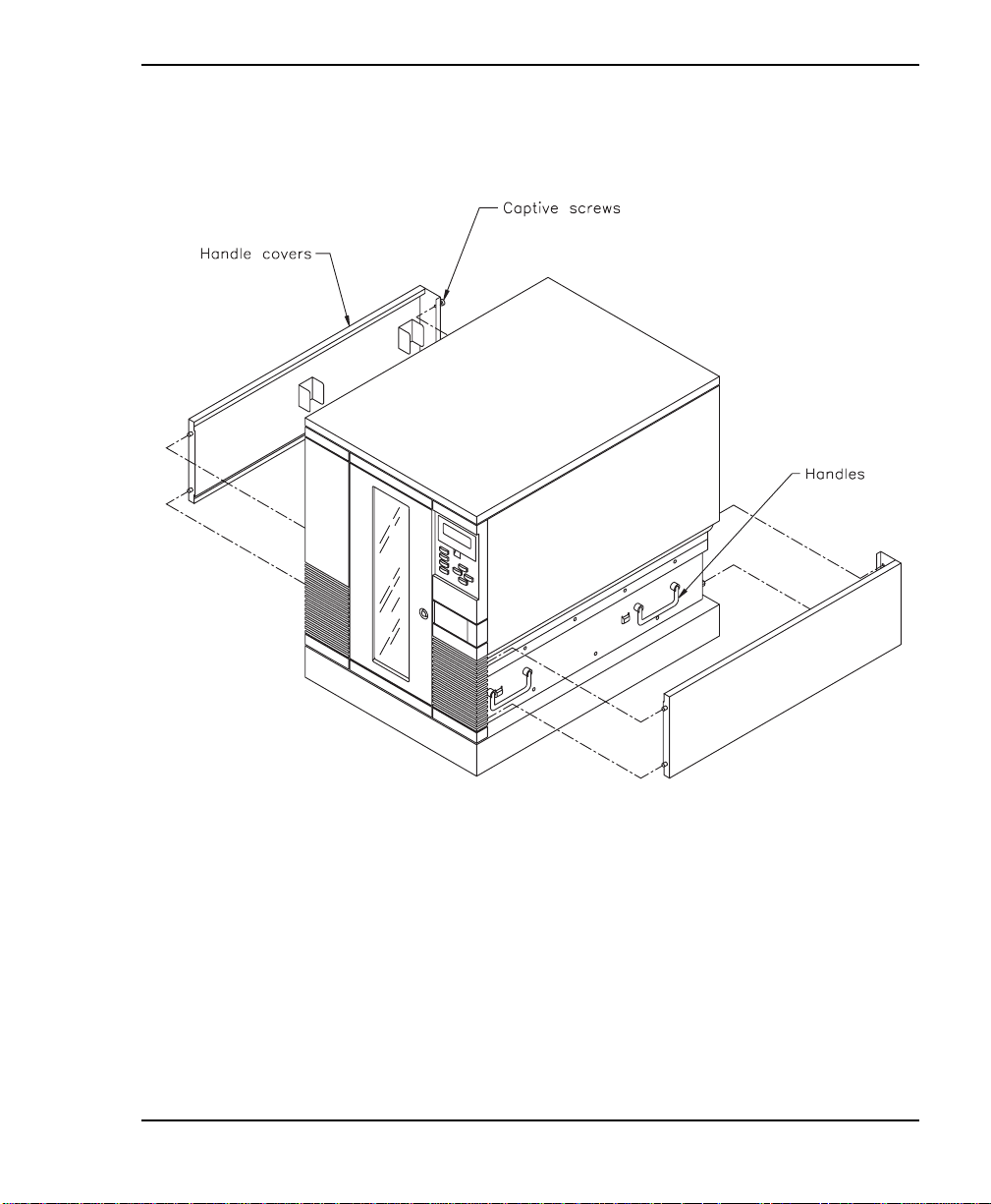
If y ou have a s tanda lone library, access the handles by
removing the side panels as described below.
Usin g a flat-blade screw driver, loosen t he captive screws
(two on each panel) at the rear of the library.
Exabyte 440 and Exabyte 480
Page 29
Hardware Installation
Pull each side panel back and away from the library, as
shown in the following figure.
Installation and Operation
15
Page 30
Chapter 2
Installing the library hardware
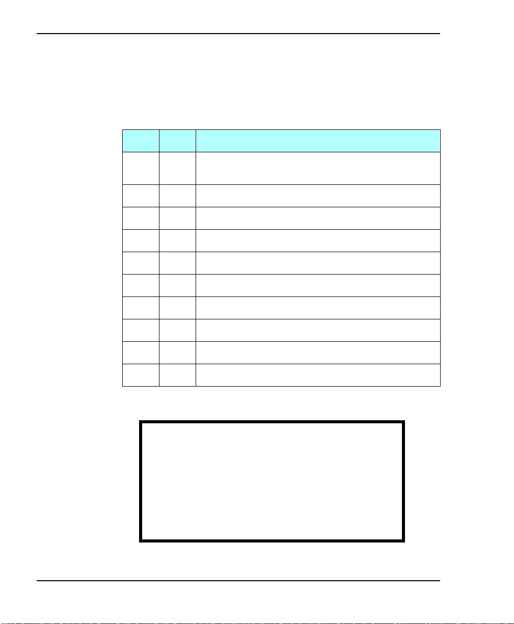
This section provides step-by-step instructions for installing the
library hardware. Use the following ta b le as a checklist.
✔
Step
1
2
3
4
5
6
7
8
9
10
Description
If you have a rac k-mount model, install the library
into a rack.
Unlock and open the door.
Remove the packing foam.
Prepare and install cartridges.
Install the cartridge magazines.
Install a cleaning cartridge.
Close and lock the front door.
Connect the library to the SCSI bus.
Connect the power cord.
Power on the library.
16
:$51,1*
Before performing a ny installation or
maintenance procedures, be sure tha t the
library power switch is in the off position and
that the power cord is disconnecte d from the
library and the outlet.
Exabyte 440 and Exabyte 480
Page 31

Hardware Installation
Step 1 – Install the rack-mount library
If you have a rack-mount library, follow these instructions to
install it into a standard EIA 19-inch rack. If you have a standalone
library, go to “Step 2 – Unlock and open the door” on page 24.
:$51,1*
The rack-mount library weighs
137–179pounds (62–81 kg); the standalone
library weighs 190 – 238 pounds (86 – 110 kg).
You need at least 4 peopl e, or 2 people and a
small fork lift, to lift eith er model.
Make sure you install the library in the lowest
poss ible loc ation in the ra ck and tha t the ra ck is
equipped with extension support legs.
Installation and Operation
Mak e sure you e xte n d the support legs bef ore
insta lling the libra ry in the rack or when sliding
it out of the rack. If you do not have extension
su pport legs, use an additional pe rson to
counterweight the back of the rack or cabinet.
17
Page 32

Chapter 2
For this procedure, you will need the following:
Standard EIA 19-inch rack equipped with extension support
legs
TO RX screwdriver with a T-25 bit
T-15 bit, if you need to extend the rails
Eight 10-32 × pan head screws
12⁄
Two 10-32 × 1.0 pan head screws
Two 8-32 × button head screws
716⁄
Ten clip nuts (provided in the accessory box), necessary if the
rack does not have threaded h oles
Two slide rails (provided in the accessory box)
18
Exabyte 440 and Exabyte 480
Page 33
Hardware Installation
Installing the slide rails into the rack
To install the slide rails into the rack:
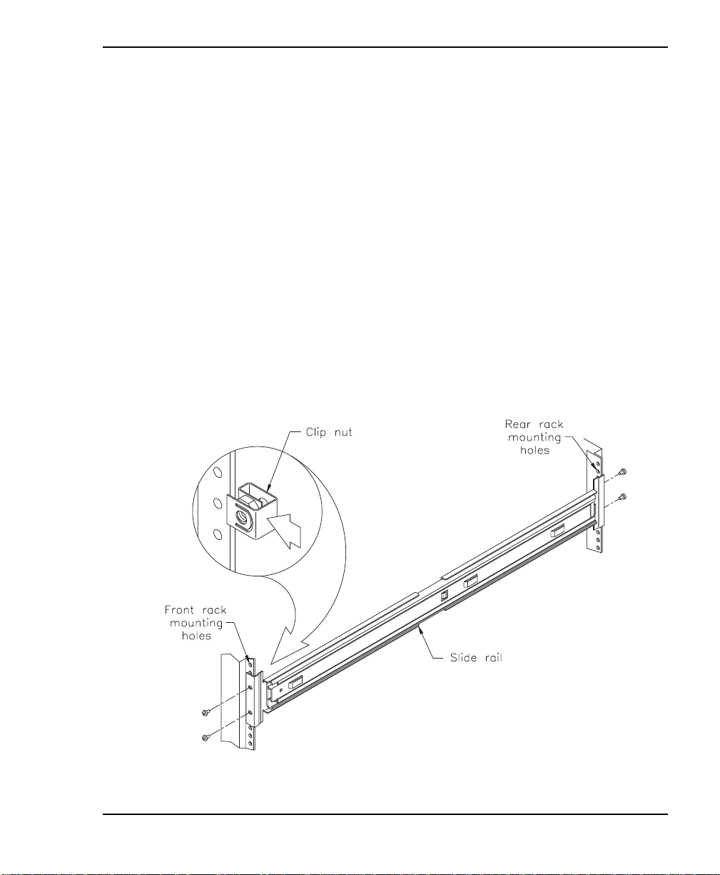
1. Locate the mounting holes on the rack where you want to
install the library. Allow 1 to 2 inches (3 to 4 cm) minimum
clearance below the bottom mounting hole.
Note: If the rack does not have threaded holes, attach eight
of the ten clip nuts over the holes (see the following
figure).
2. Using a T-25 TORX driver and eight (four for each rail)
10-32 × pan head screws, attach, but do not tighten, the
slide rails to the rack (see the following figure).
12⁄
Installation and Operation
19
Page 34
Chapter 2
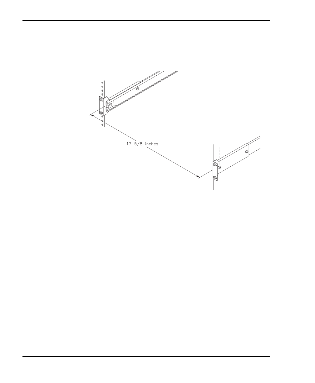
3. Adjust the distance between the mounting brackets on each
side of the cabinet to 17 inches (44.8 cm), as shown in the
58⁄
following figure. Measure both the front and the back.
20
4. Use a T-25 TORX screwdriver to tighten the screws to
12.0 in-lbs (13.8 kg-cm) of torque.
Installing the library into a rack
To in stall the libra ry int o a rack:
1. Extend the exten sion support legs on the rack.
Exabyte 440 and Exabyte 480
Page 35
Hardware Installation
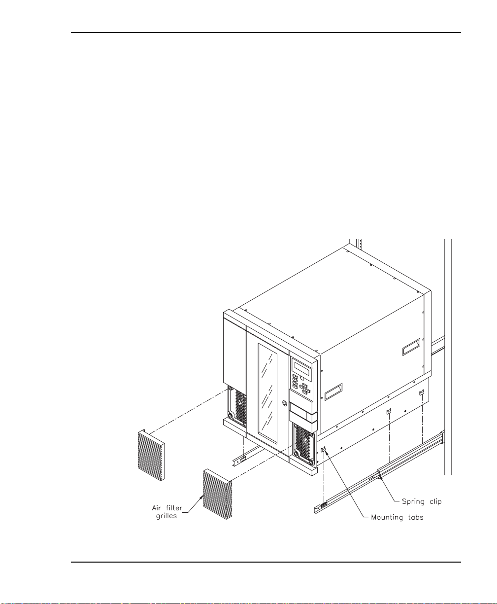
2. Slide the inside ra ils as far o ut of t he r ack as possible (see the
following figure).
3. Remove the air fi lter grilles from the front of the library by
lifting the outside edges and pulling the grilles away from the
library (see the fo llowing figure).
4. Using four people, or two people and a fork lift , lift the lib rary
by the handles and lower it onto the slide rails s o the mounting
tabs on each side of the library fits into the slots in the rails (see
the following figure). Make sure all six mounting tabs are fitted
securely into the slots.
Installation and Operation
21
Page 36
Chapter 2
5. Press the spring clips and slide the library most of the way into
the rack keeping the screw hole in the front of the slide rails
accessible.
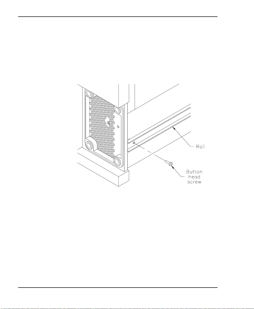
6. Install one 8-32 × button head screw into the screw hole
716⁄
on each rail, as shown in the follo wing figure.
22
Exabyte 440 and Exabyte 480
Page 37
Hardware Installation
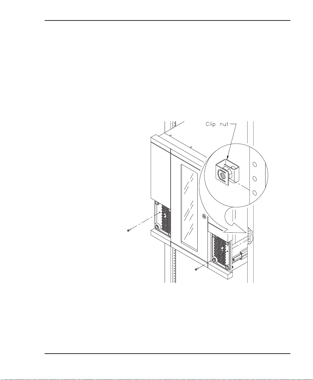
7. If the ho les in the rack are not threaded, install a clip nut o n
each side of the rack in line with the screw hole in the front
panel of the library, as shown in the following figure.
8. Slide the library completely into the rack. Using a T-25 TORX
screwdriver, insert the two 10-32 × 1.0 pan head screws into
the front pa nel, as s hown in the fol lowing figur e. These scr ews
prevent the library from sliding out of the rack.
9. Replace the air filter grilles on each side of the front panel.
Installation and Operation
23
Page 38
Chapter 2
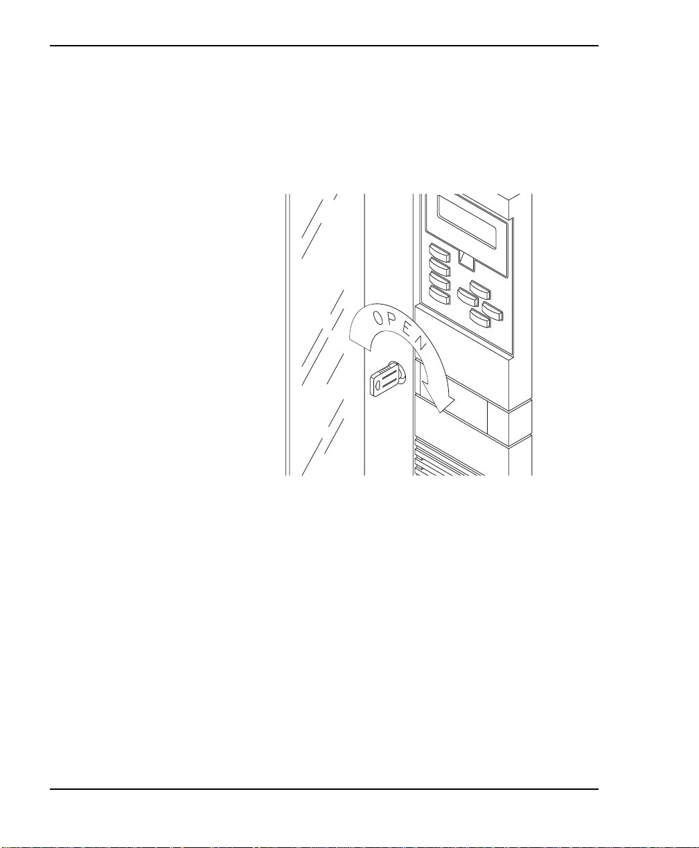
Step 2 – Unlock and open the door
To open the door, insert the key from your accessory ki t i nto the
lock, push in, and turn it one-quarter turn to the right, as shown
in the following figure. Pull the door open.
24
Exabyte 440 and Exabyte 480
Page 39
Hardware Installation
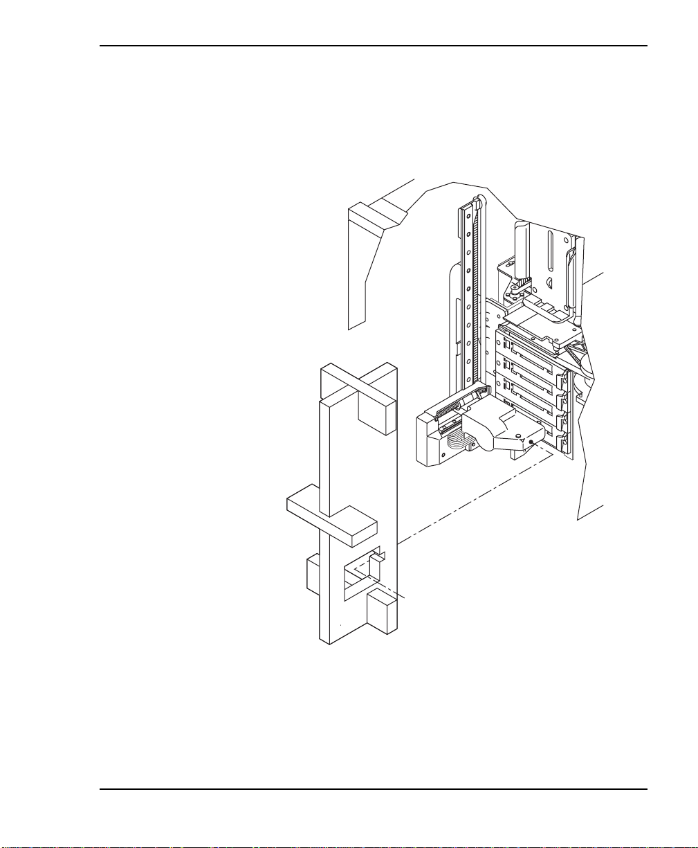
Step 3 – Remove the packing foam
Remove the packing foam from the library as shown in the
following figure.
Installation and Operation
25
Page 40

Chapter 2
Step 4 – Prepare and install cartridges
Two types of Exatape™ 8mm Data Cartridges are available:
advanced metal evaporated (AME) and metal particle (MP).
Exabyte Mammoth tape dri ves write and read A ME tape and read,
but do not write, MP tape. Eliant 820 tape drives write and read
MP tapes, but do not support AME tape.
➤ Important B eca use of media mana gement a nd
application software issues, Exabyte recommends
that you do not mix AME and MP data cartridges
in the same library. If you must mix AME and MP
cartridge s, contact your application software
vendor.
Always us e Exabyte media to achieve the best tape drive
performance. The tape drives are tested to specifications using
Exabyte media at the factory.
26
Exabyte 440 and Exabyte 480
Page 41
Hardware Installation
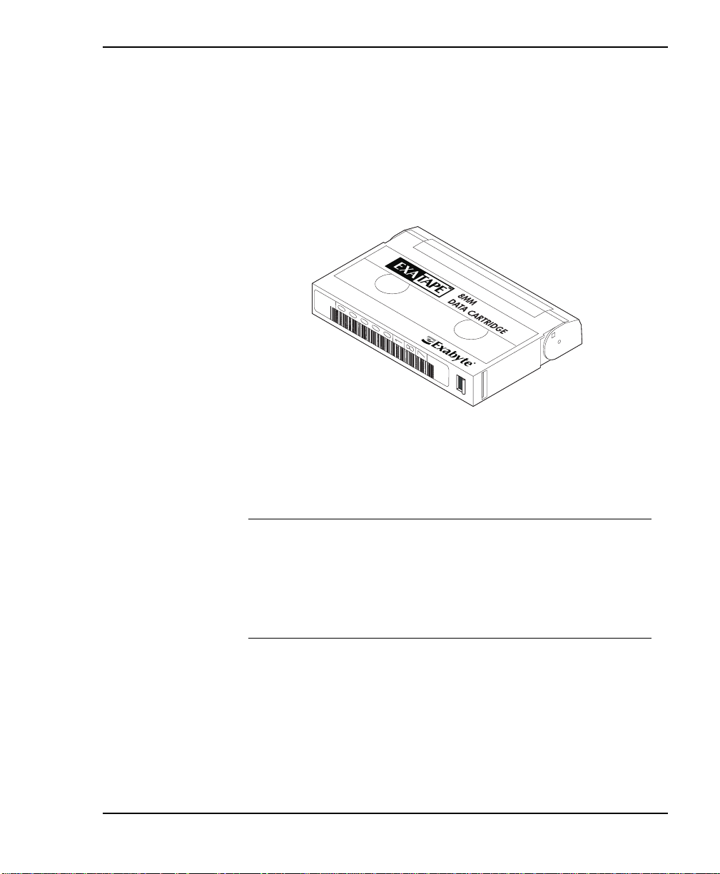
To prepare and install cartridges:
1. Affix a bar code label to each cartridge by positioning the label
as shown in the following figure, using the recessed area on
the cartridge for guidance. Make sure you ori ent the label
correctly.
For information on how to prepare bar code labels, refer to the
Exabyte Bar Code Label Specification for 8mm Cartridges.
➤ Important I f you remove a ba r code la be l from
Installation and Operation
a cartridge without replacing it, make sure you
cle an the la bel a rea thoroughly. B ar code labels can
lea ve adhe s ive on the labe l a rea , which ma y ca use
the cartridge to stick to the gripper.
27
Page 42
Chapter 2
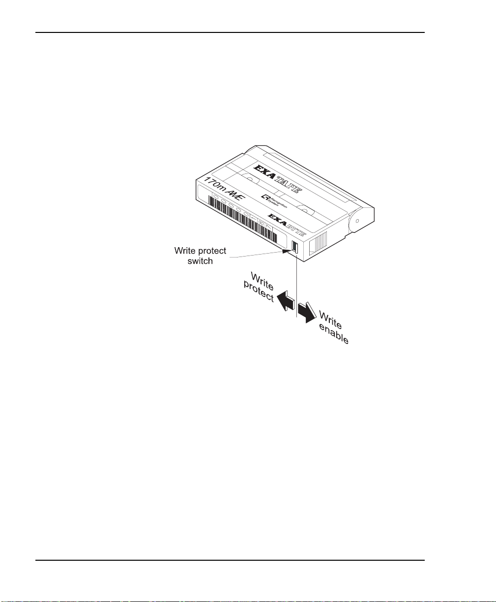
2. Make s ure t he wri te-p rot ect s wi tches on the ca rtr i dges ar e set
appropriately, as shown in the following figure. You can use
a ball-point pen or similar instrument to move the
write-protect switch. If the write-protect switch window is
red, the cartridg e is write-pro tected.
28
Exabyte 440 and Exabyte 480
Page 43
Hardware Installation
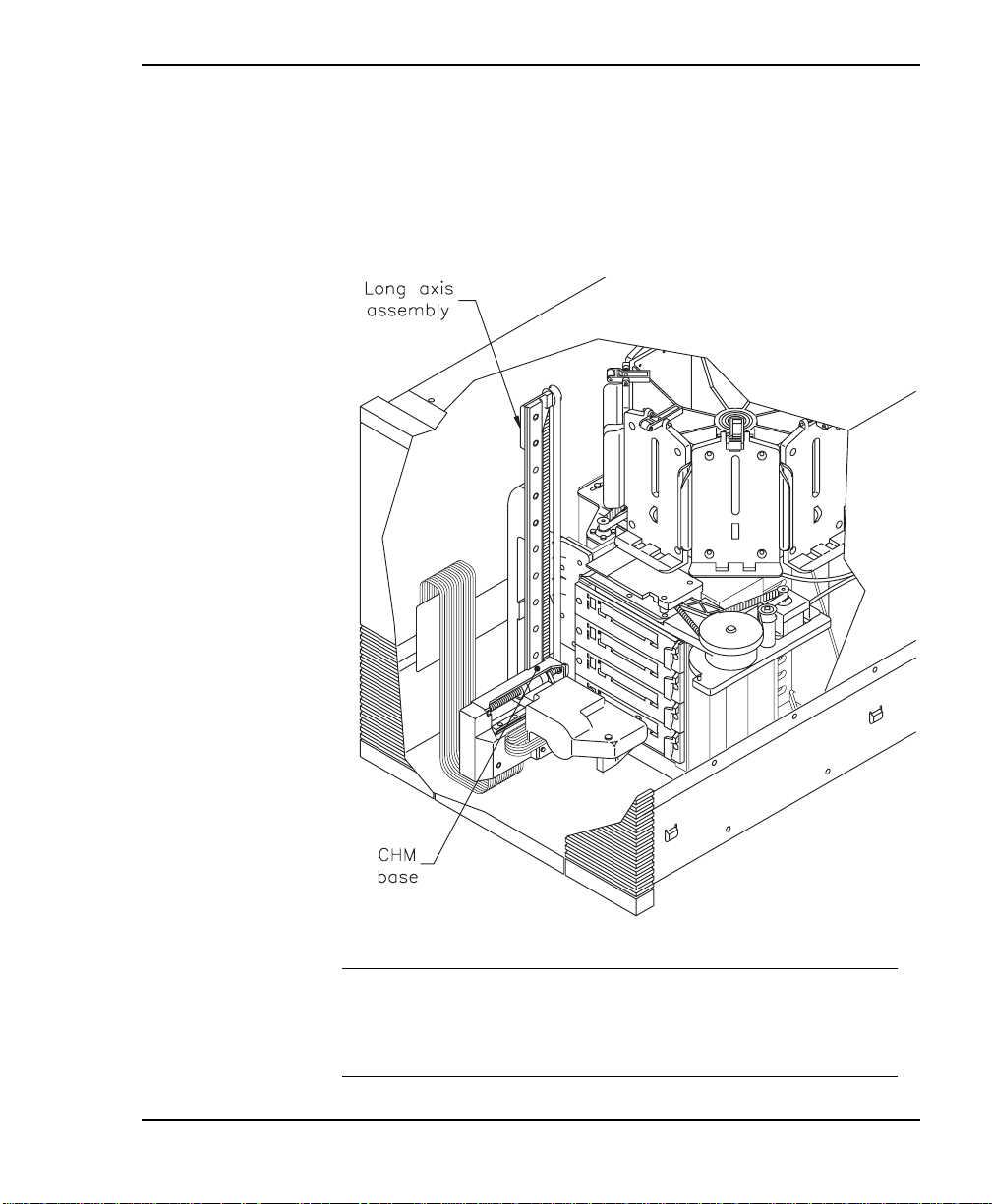
3. If necessary, move the cartridge handling mechanism (CHM)
so it is not blocking the magazine mounting plates on the
drum. To move the CHM, reach in through the door and push
against the base of the CHM, sli di ng i t fi r ml y to the bottom of
the long axis until it stops, as show n in the following figure .
➤ Important Do not touch the lens on the bar
Installation and Operation
code scanne r; smudges on the lens can cause
scanning errors.
29
Page 44

Chapter 2
4. Remove the cartridge magazine by pulling it out first from the
top and then the bottom.
CAUTION
Make sure the CHM and cabling are safely out of
the way before you remove or insta ll the
cartridge magazine.
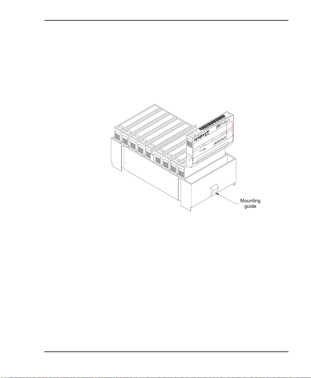
5. Place t he maga zine on i ts f eet wi th the si ngl e mounti ng gui de
toward the right, as shown in the following figure.
6. Position each cartridge s o that the bar code label i s on top and
the write-protect switch is toward the front, as shown in the
following figure.
30
Exabyte 440 and Exabyte 480
Page 45
Hardware Installation
7. Insert the cartridge into the magazine slot.
Note: Very little force is needed to install a da ta car tri dge. If
it does not snap into place easily or if it protrudes
further than the magazine’s center rib, check the
orientation of the cartridge.
Installation and Operation
31
Page 46

Chapter 2
Step 5 – Install the cartridge magazines
➤ Important Use only magazines designed for
E xabyte 440 and Exabyte 480 libraries. Do not use
magazines designed for full-high Exabyte 8mm
libraries.
Note: The Exabyte 440’s four magazine mounting plates are
installed on every other mounting plate position on the
drum, with the mounting plate identifiers 0, 1, 2, and 3.
CAUTION
Make sure the CHM and its cabling are safely
out of the way be fore you re move or insta l l the
cartridge magazines.
32
To install a cartridge magazine:
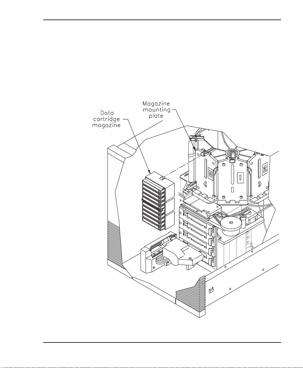
1. If necessary, manually rotate the drum to access the mounting
plate where you want to install the magazine.
2. On the magazine mounting plate, locate the roller on the top
of the plate.
Exabyte 440 and Exabyte 480
Page 47
Hardware Installation
3. Make sure the cover is removed from the magazine and
positio n the magazine so that the magazine is al igned with the
roller on the mounting place, as shown in the following figure.
4. Insert the bottom end of the magazine first, then snap the
magazine in to place by pressing against the top.
Installation and Operation
33
Page 48

Chapter 2
Step 6 – Install a cleaning cartridge
The following p rocedure desc ribes how to manually install a
cleaning cartridge in the fixed cartridge slot. To replace this
cartridge after the library has been in operation, use the Remove
Cartridge and Insert Cartridge options on the Maintenance Menu
and the entry/exit port, as described on page 73.
➤ Important If you a re us i ng Exa byte Mammoth
tape d rives, use an Exabyte Mammoth 8mm
Cleaning Cartridge (or a cleaning cartridge
approved by Exabyte for use with Mammoth).
If you are using the Elian t 820 tap e drives, use an
Exabyte Premium 8mm Cleaning Cartridge (or a
clea ning cartridge approved by Exabyte for use
with your tape drive).
34
The Mammoth tape drive ejects all other 8mm
cleaning cartridges, and the Eliant 820 ejects
Mammoth 8mm Cleaning Cartridges.
CAUTION
Use Exabyte or Exabyte-approved cleaning
cartridges only. Using cloth swabs, cotton
swabs , c le aning agents , or cle aning cartridge s
not approved for your tape drive by Exabyte
may void the tape drive warranty.
Exabyte 440 and Exabyte 480
Page 49
Hardware Installation
➤ Important I f you wan t to clea n the drives usin g
the C lea n Drives Menu on the LC D, you must install
a cleaning cartridge in the fixe d c artridge slot.
To install a cleaning cartridge in the fixed cartridge slot:
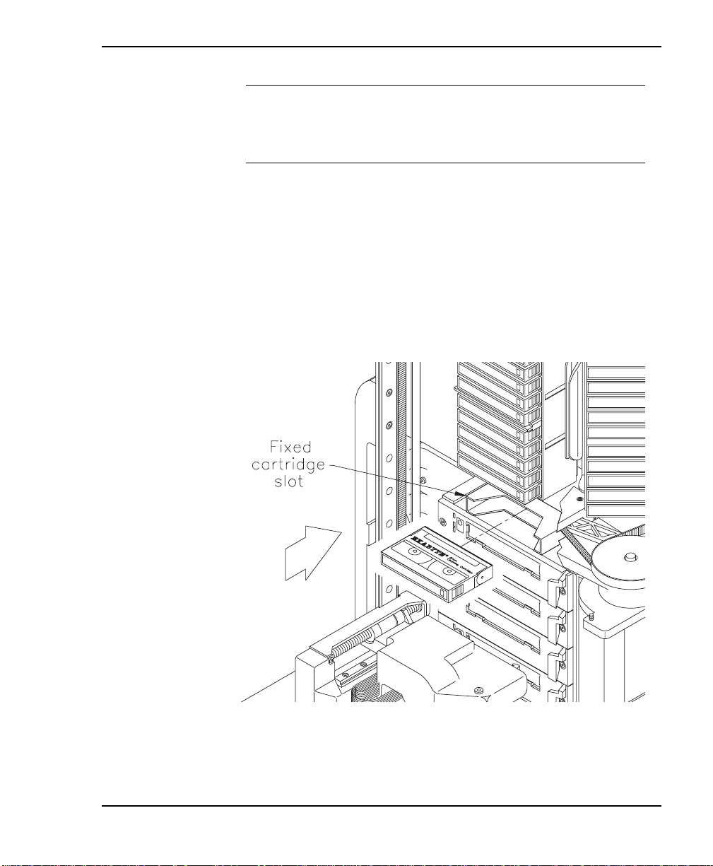
1. Position the cartridge so that the window showing the tape
reels is to the top (see the following figure).
2. Insert the cartridge into the fixed cartridge slot until it snaps
into place.
Installation and Operation
35
Page 50

Chapter 2
Step 7 – Close and lock the front door
Close the library door and turn the key one-quarter turn to the
left. Remove the key and keep it in a safe place.
Step 8 – Connect the library to the SCSI bus
This section contains general guidelines for connecting the library
to the SCSI bus. The SCSI connectors for the library and tape
drives are accessible through the cabling bay at the back of the
library.
➤ Important If you have an Exabyte 440 or
Exabyte 480 with Eliant 820 tape drives and the
library is not the last device on the SCS I bus, you
may need to ins tall ferrite cla mps on a SCSI c able
to mainta i n c omplia nce with the CISPR 22 Class B
sta nda rd. I f nec e ss a ry, fe rrite c la mps a re provided
with the libra ry; se e the ins tructions pack age d with
the clamps for more information.
36
Before you begin
1. Make certain the host computer and any peripheral devices
are powered off.
CAUTION
To avoid damaging the tape drives, make sure
the tape drives and library are powered off when
you connect the library to the SCSI bus.
Exabyte 440 and Exabyte 480
Page 51

Hardware Installation
2. If y ou are un familiar with c onnecting devices on a SCSI bus,
first read Appendix B.
3. Dete rmi ne the S CSI bus conf igu ra tio n (tha t is , how man y SC SI
buses you will connect to the library and which bus you will
connect to which device).
4. Be awa re t hat yo u c an c onnec t s i ng l e-end ed and l ow -v o lt ag e
differential (LVD) SCSI devices to the same SCSI bus. Mixing
the two types of devices results in all devices on the bus
operating as single-ended devices.
CAUTION
Do not connect an LVD library to an HVD SCSI
bus , or you ma y da ma ge the de vic e s a tta c he d to
the bus.
Installation and Operation
37
Page 52
Chapter 2
Connecting the narrow library to the SCSI bus
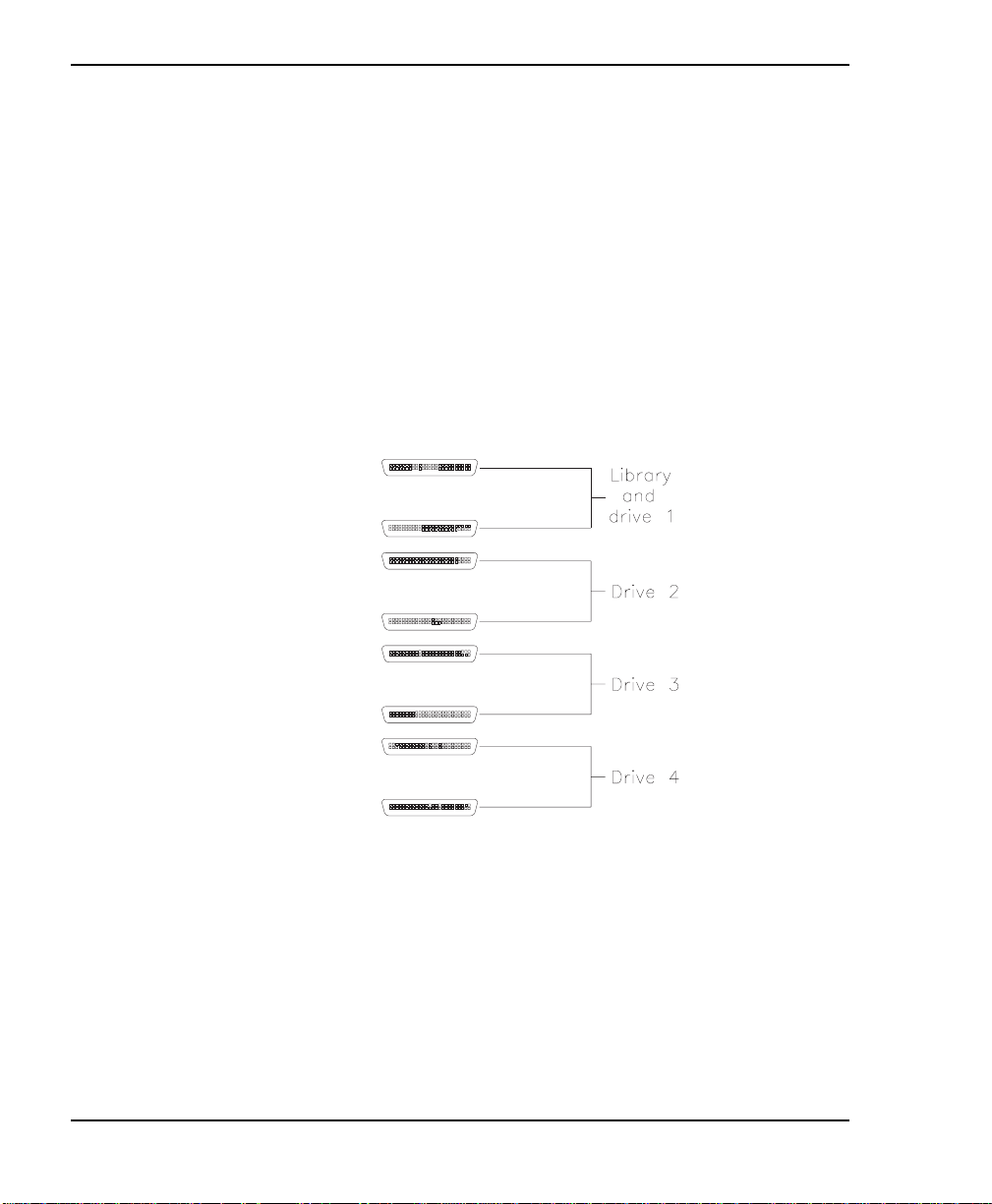
Narrow SCSI libraries have eight connectors and can operate on
up to four SCS I buses. The library an d Drive 1 share connectors
and must operate on the same SCSI bus. Drives 2 through 4 can
operate on individual buses.
To connect the narrow library to the SCSI bus:
1. Connect the library to the SCSI bus, using the connector
assignments shown in the following figure.
38
2. Install SCSI cables as required to connect the library devices
to the other devices on the SCSI bus.
Exabyte 440 and Exabyte 480
Page 53

Hardware Installation
3. If more than one device in the library is on the same bus, place
a jumper between the appropriate connectors. (For narrow
libr aries, note that you do not need to install a jumper between
the library and the uppermost tape drive si nce they share the
same connectors.)
4. For each device that terminates the bus (either the librar y or
one of the tape drives), install a terminator on one of the
connectors for that device. See the following section for an
example of a narrow SCSI library connected to two bu ses.
Installation and Operation
39
Page 54
Chapter 2
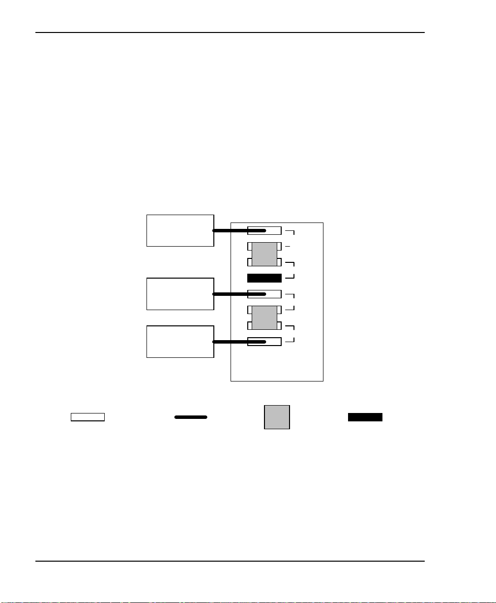
Example: Narrow library on two SCSI buses
On SCSI Bus A, a cable connects the host to the library and
Drive 1, and a jumper connects the library and Drive 1 to Drive
2. Bus A is termi nated with an external terminator i nstalled on
the lower connector for Drive 2.
On SCSI Bus B, a cable connects a second host to Drive 3, and
a jumper connects Drive 3 to Drive 4. A cable connects Drive 4
to the other devices on Bus B.
Bus A
Bus B
SCSI
connector
Host for
Bus A
Host for
Bus B
other devices
on Bus B
SCSI
cable
Library and
Drive 1
Drive 2
Drive 3
Drive 4
SCSI
jumper
Terminator
40
Exabyte 440 and Exabyte 480
Page 55
Hardware Installation
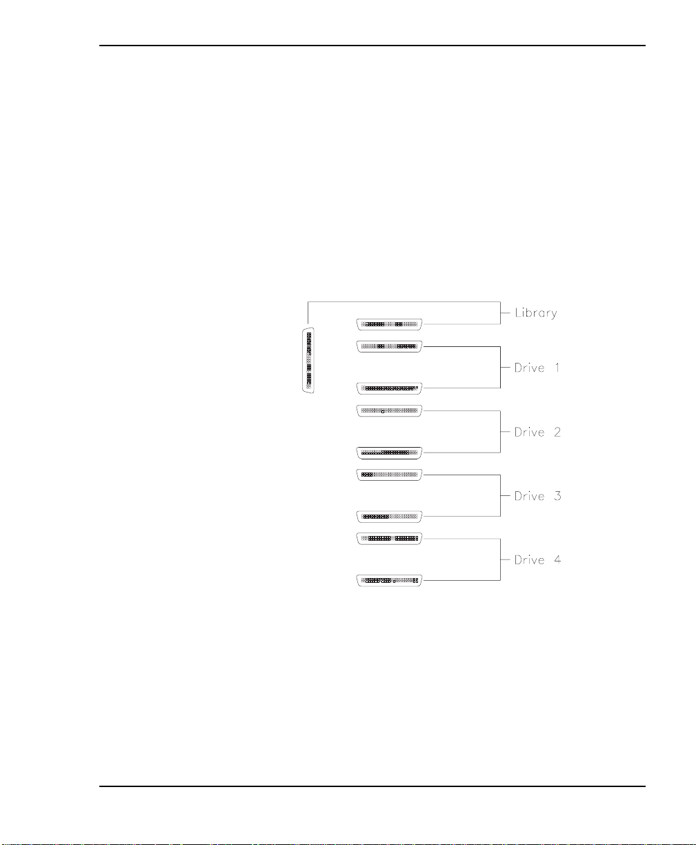
Connecting the wide SCSI library to the SCSI bus
Wide SCSI libraries have ten conne ctors and can be attached to
up to five SCSI buses (all four tape drives and the library can be
on separate buses).
To connect the wide library to the SCSI bus:
1. Connect the library to the SCSI bus, using the connector
assignments shown in the following figure.
2. Install SCSI cables as required to connect the library devices
to the other devices on the SCSI bus.
Installation and Operation
41
Page 56
Chapter 2
3. If more than one device in the library is on the same bus, place
a jumper between the appropriate connectors.
4. For each device that terminates the bus (either the librar y or
one of the tape drives), install a terminator on one of the
connectors for that device. See the following section for an
example of a wide SCSI library connected to t wo buses.
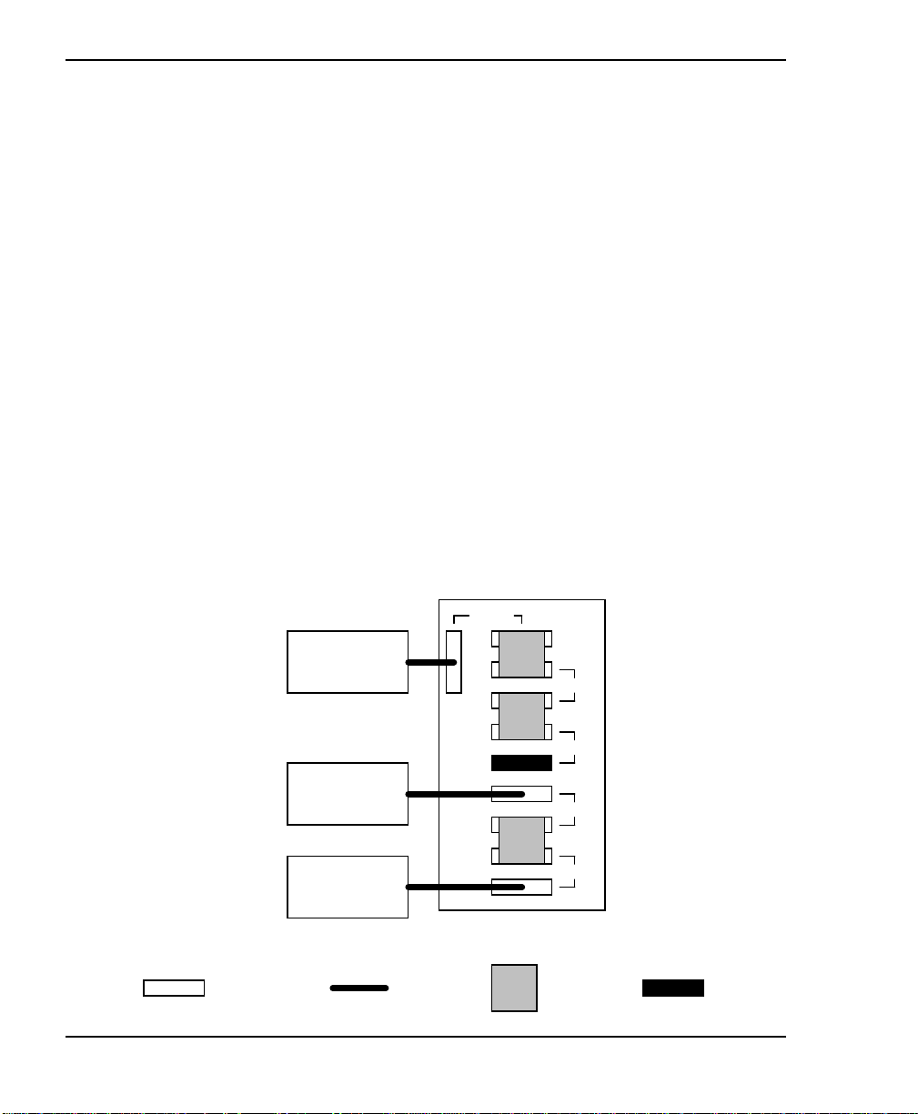
Example: Wide library on two SCSI buses
On SCSI Bus A, a cable connects the host to the library, and
jumpers connect the librar y to Drive 1, and Dri ve 1 to Drive 2.
Bus A is terminated with an external terminator installed on
the lower connector for Drive 2.
On SCSI Bus B, a cable connects a second host to Drive 3, and
a jumper connects Drive 3 to Drive 4. A cable connects Drive
4 to the other devices on Bus B.
42
Bus A
Bus B
SCSI
connector
Host for
Bus A
Host for
Bus B
other devices
on Bus B
SCSI
cable
Library
Drive 1
Drive 2
Drive 3
Drive 4
SCSI
jumper
Terminator
Exabyte 440 and Exabyte 480
Page 57

Hardware Installation
Step 9 – Connect the power cord
➤ Important The power cord shipped with the
library is a 120 VAC three-conductor power cord
for use in the United States or Canada. I f you are
pla nning to use a nother input volta ge or if you plan
to use the library outs ide of the U. S. or C a nada , you
must su pply your own power cord. For more
information, refer to Appendix A.
1. Make sure that the power switch on the back of the libr ary i s
off (the 0 is pressed
2. Connect the female end of the power cord to the power
connector on the back of the library.
).
3. Plug the male end of the power cord into the powe r source.
Note: The library has autoranging voltage selection, so you
Step 10 – Power on the library
1. Make sure the library’s door is clo sed and locked.
2. Power on the host computer.
Note: If your host requires t hat attached peripheral d evices
3. Push the power switch on the back of the library to the on (I)
position.
Installation and Operation
do not need to change the voltage setting.
be powered on before the host, power on the library
before powering on the host.
43
Page 58

Chapter 2
4. Wait while the library performs its power-on self-test. During
this time, the following activities occur:
The cooling fan begins to rotate.
Th e LCD illumin ates and displays t he M ain Screen.
The tape drives perform their power-on self-tests.
The library performs its power-on self-test.
If problems occur...
If the l ibra ry does not power on
as described
If an error c ode i s dis pla ye d on
the LCD
If you cannot solve the
problem yourself
Check the following:
Is the power switch on? (I s the
I pressed?)
Is the power cord inserted
correct ly?
Is the library door closed and
locke d?
Is the SCSI bus terminated?
Is the host computer system
turned on?
Is the SCSI cable connected to
the library and host computer?
See Appendix C for a list of error
codes and corrective actions.
Contact your service provider or
Exabyte Technical Support.
44
Exabyte 440 and Exabyte 480
Page 59

3Configuration
A fter installing the library hardware, you need to set or check the
library’s configuration options. This chapt er describe s:
Using the operator panel for setting configura tion options
Displaying the configuration menu
Setting the SCSI IDs (required)
Setting other configuration options, if necessary
Setting robot control modes
Installation and Operation
45
Page 60
Chapter 3
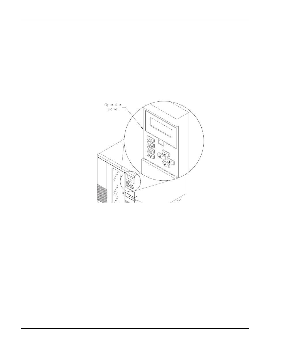
Using the operator panel
The library includes a four-line LCD and keypad, called the
operator panel, that allows you to control l ibr ary operations. U sing
the operator panel (shown in the following figure), you can set
library options, check operating statistics, and diagnose errors. If
desired, you c an tilt the LCD for easier viewing.
46
Exabyte 440 and Exabyte 480
Page 61
Configuration
Operator keys
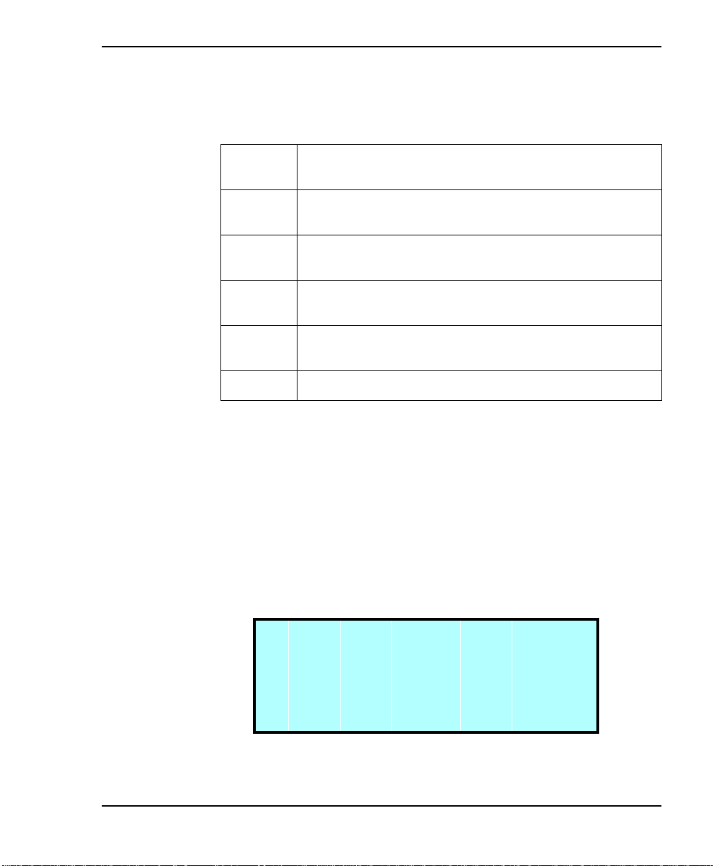
The keys on the operator panel perform the following functions:
>@>@
>@>@
>(QWHU@
>(VFDSH@
>5HVHW@
>+HOS@
Scrolls the screen arrow (→) up or down. The screen
arrow points to the current selection.
In some screens, moves the screen arrow left or right.
On some menu selections, toggles an option on or off.
Selects the item next to the screen arrow or accepts a
change.
R eturns to the previous menu or screen, or cancels an
operation without saving ch anges.
Dis pla ys the R es et s cre en, which a llows you to r ese t the
library and the tape drives.
Displays the Help screen. To exit Help, press >(VFDSH@.
Main Screen
The Main Screen appears when you apply power to the library.
The first and second li nes on the Main Screen display the product
name, version, and the current time. The third and fourth lines
display status information about the library and tape drives; and
if a hardware error occurs these lines display information about
the erro r. A n ex am ple of the M ai n Scr een wi th a s ta tus mess a ge i s
shown below.
V E R
S t a t u s : M o v e 1 - D
P i c k i n g F r o m S l o t 1
Note: The exact w ordi ng of t he Main Sc reen may b e dif ferent on
Installation and Operation
E x a b y t e E X B - 4 4 0
n.n n.n n h h:m m : s s
your screen.
47
Page 62

Chapter 3
Error codes
If a library hardware error occurs, an error code appears on the
third and fourth lines of the Main Screen. The third line provides
the error’s n umerical cod e; the fou rth line provides a brie f
explanation of the error. You must correct the error before
operation can continue. (Refer to Appendix C for a list of error
codes and corrective actions.)
E x a b y t e E X B - 4 4 0
V E R
S t a t u s : E r r o r 1 1
S O U R C E E M P T Y
n.n n.n n h h:m m:s s
Main Menu
Use the Main Menu (shown below) to access LCD options and
functions. To access the Main Menu, press
Screen.
M a i n S c r e e n
→
E x t e n d / R e t r a c t E / E
I n t e r f a c e M e n u
C o n f i g u r a t i o n M e n u
>(VFDSH@
from the Main
↓
48
Exabyte 440 and Exabyte 480
Page 63
Configuration
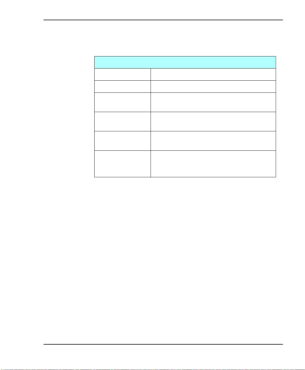
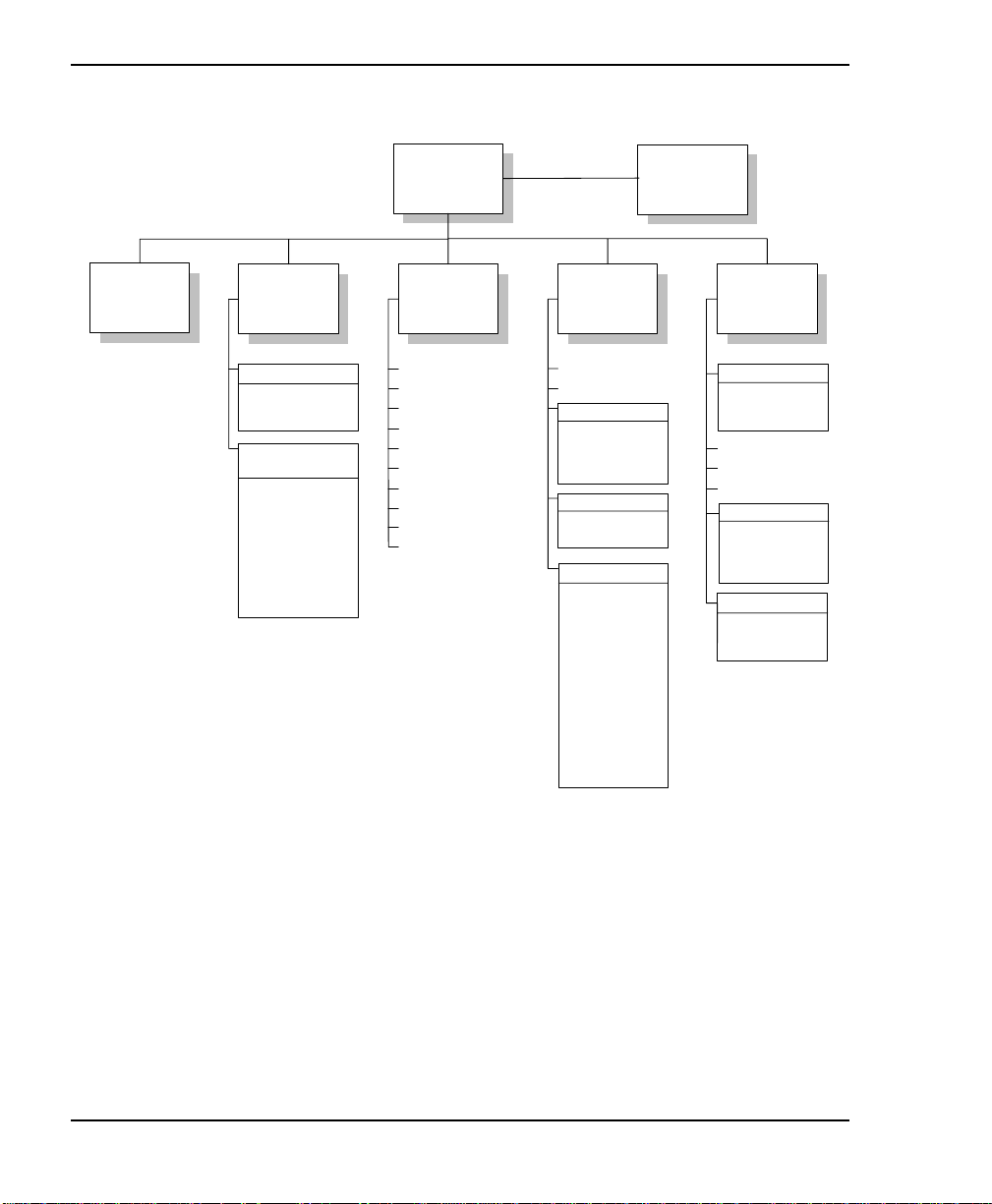
The selections on the Main Menu are describ ed in the following
table. The menu structure is shown on the next page.
Main Menu Selections
Main Screen Returns to the Main Screen.
Extend/Retract E/E Allows you to control the entry/exit port
Interface Menu Allows you to specify how CHM motion is
controlled and to configure the serial ports.
Configuration
Menu
Maintenance
Menu
Library Info Menu Provides tape drive status information and
Allows you to set SCS I IDs, security, and
other configuration options.
Allows you to clean the tape drive and
perform diagnostics.
diagnostic information for service
technicians.
.
Installation and Operation
49
Page 64
Chapter 3
Extend/
Retract E/E
Interface
Menu
Control Mode Menu
LCD Interface
SCSI Interface
25/9-Pin Serial Port*
Config 25/9-Pin
Menu*
Connect Drive 1
Connect Drive 2
Connect Drive 3
Connect Drive 4
Diag Console
Baud Rate: 1200
Baud Rate: 2400
Baud Rate: 4800
Baud Rate: 9600
Baud Rate: 19200
* Your LCD may show
two entries:
Config 25-Pin Port and
Config 9-Pin Port
Main Menu
Configuration
Menu
Set SCSI IDs
SCSI Parity
Adjust Contrast
Back Light
Set Date
Set Time
Set Security
Set Serial Number
Set Max Addr Elem
Use Mammoth
Maintenance
Menu
Insert Cartridge
Remove Cartridge
Clean Drives Menu
Clean Drive 1
Clean Drive 2
Clean Drive 3
Clean Drive 4
Demo Menu
Slot Demo
Drive Demo
Diagnostics Menu
Self Test
Position to Elem
Park
Move Cartridge
Scan
Scan w/Range
Home Gripper
Home CHM
Cycle Pick/Place
Cycle Gripper
Cycle S Axis
Cycle L Axis
Cycle Solenoid
Cycle Drum
Cycle E/E
Main Screen
Statistics
System Sensors
Command History
Inventory Menu
Label Information
Occupied Info
Position Info
Library Info
Menu
SCSI Menu
SCSI Mode Params
SCSI Reservations
SCSI Sense Data
Drive Info Menu
Drive 1 Status
Drive 2 Status
Drive 3 Status
Drive 4 Status
50
Exabyte 440 and Exabyte 480
Page 65

Displaying the Configuration Menu
Use the Configuration Menu to view and change the
configuration options for your library. To display the
Configuration Menu:
1. Access the Main Menu by pressing >(VFDSH@on the keypad. The
Main Menu appears:
M a i n S c r e e n
→
E x t e n d / R e t r a c t E / E
I n t e r f a c e M e n u
Configuration
C o n f i g u r a t i o n M e n u
2. Press
until the screen arrow points to the Configuration
>@
Menu. T hen press
S e t S C S I I D s
→
S C S I P a r i t y O N
A d j u s t C o n t r a s t
B a c k L i g h t O N
. The Configuration Menu appears:
>(QWHU@
↓
↓
Installation and Operation
51
Page 66

Chapter 3
Setting the SCSI IDs
Default SCSI IDs are assigned at the factory for the library and
each tape drive. Drive blanks are assigned B (for blank). This
section describes how to view the default settings and change
them if necessary.
➤ Important The lib ra ry and tape drives must
each have a unique SCSI ID within each SCSI bus.
Because you may have multiple SCSI buses, the
library does not check for duplicate SCSI IDs. It is
your responsibility to make sure you do not assign
duplicate SCSI IDs withi n a SCSI bus.
To view or change SCSI IDs:
52
1. From the Configuration Menu, select Set SCSI IDs. The
following screen appears:
S C S I D 4 D 3 D 2 D 1 L I B
I D s : 0 5 0 4 0 3 0 2 0 1
↑
↓ →
Note: The SCSI IDs s how n ar e ex am pl es o nly ; yo ur s et ti ng s
may differ. If one of the drive carrier slots contains a
drive bl ank, the lib rar y di s pla ys a B (for blank) instead
of a SCSI ID.
2. To set the SCSI ID for the bottom tape drive (D4) , pres s
until the screen displays the desired SCSI ID.
>@
Exabyte 440 and Exabyte 480
>@
or
Page 67

Configuration
3. Press >@ to move the screen arrows to D3, as shown. Press >@
or >@ until the screen displays the SCSI ID you want.
S C S I D 4 D 3 D 2 D 1 L I B
I D s : 0 5 0 4 0 3 0 2 0 1
↑
← ↓ →
Note: If any drive carrier slot contains a drive blank, the
cursor will skip over the SCSI ID field for that slot.
4. Continue this process until you have set the SCSI IDs for all
tape drives and the library.
5. When the SCSI IDs for all tape drives and the library are
correct, press
to accept your choices.
>(QWHU@
6. If you have changed one or more of the tape drive IDs, the
following screen appears:
P r e s s E N T E R t o r e s e t
7. Press
and returns to the Configurati on Menu.
Installation and Operation
t h e d r i v e ( s ) o r E S C
t o c a n c e l t h e S C S I
I D c h a n g e s .
. The library resets the tape drives wi th changed IDs
>(QWHU@
53
Page 68

Chapter 3
Setting the rem aining configuration options
The Configuration Menu contains other configuration options
described in the following sections. If desired, you can check these
settings and change them.
SCSI Parity
The SCSI Parity option allows you to enable parity checking for
the library ( if the SCSI adapter card connected to the librar y
supports it ). When this option is enabled, the library check s all
data coming acros s the SCSI bus for parity . The setting you specify
remains in effect across power cycles.
Note: Parity checking can also be enabled and disabled by the
application software using a S CSI MO DE SELECT
command. The method last used to set parity checking
(LCD or SCSI command) has precedence.
54
Parity checking for tape drives is set separately. See the
tape drive’s SCSI referen ce for more information.
To change SCSI parity:
1. From the Config uratio n Menu , scroll u ntil the screen a rrow
points to SCSI Parity.
2. Press and 0 to toggle parity checking on and off.
3. Press
>(VFDSH@
to return to the Main Menu.
Exabyte 440 and Exabyte 480
Page 69

Configuration
Adjust Contrast
The A djust Contrast option controls the brightness of the lettering
on your LCD. To adjust the contrast:
1. From the Configuration Me nu, select Adjust Contrast. The
following screen appears:
L C D C o n t r a s t
L o w H i g h
←
M i n . . . . . . . | . . . . . . M a x
→
2. Press 0 and to change the contrast, then press
Back Light
The Back Light option turns the LCD background on or off. To
change the back light:
1. From the Config uratio n Menu , scroll u ntil the screen a rrow
points to Back Light.
2. Press and 0 to toggle back lighting on and off.
3. Press
>(VFDSH@
to return to the Main Menu.
>(QWHU@
.
Installation and Operation
55
Page 70

Chapter 3
Set Date
The Set Date option allows you to set the date for the librar y. The
date a ppear s on t he Comma nd Hi st ory sc reen (s ee page 106) and
on diagnostic listings (see Exabyte 440 and Exabyte 480 8mm Libraries
Maintenance). To set the date:
1. From the Configuration Menu, select Set Date. The following
screen appears:
S e t M o n t h D a y Y e a r
D a t e : J a n 0 3 1 9 9 9
↑ →
2. Press 4 and 6 to cycle through the selections under Month,
Day, and Year. Use and 0 to move between the columns.
56
3. Press
to save your changes and exi t the Set Date screen.
>(QWHU@
Exabyte 440 and Exabyte 480
Page 71

Configuration
Set Time
The Set Time option allows you to set the time that is shown on
the library’s Main Screen and Command History screen (see
page 106). To set the time:
1. From the Configuration Menu, select Set Time. The following
screen appears:
S e t H H : M M : S S
T i m e : 2 0 : 2 2 : 0 9
↑ →
↓
2. Use 4 and 6 to toggle through the selections under HH
(ho urs), MM (minutes), and SS (seconds). Use and 0 to
toggle bet ween the columns.
3. Press
Installation and Operation
to save your changes and exit the Set Time screen.
>(QWHU@
57
Page 72

Chapter 3
Set Security
The Security option allows you to prevent unauthorized
personnel from disrupti ng the operation of the libr ary. When you
enable security, the following activities are prevented:
Changing SCSI IDs
Changing SCSI parity checking
Changing the control mode
Setting the library serial number
Changing the installed tape drive model
Using the LCD Diagnostics Menu and Demo Menu
Using the Clean Drives Menu
Opening the front door
Communicating with a tape drive acro ss a serial port
Extending the entry/exit port
If you attempt to perform any of these operations when security
is enabled, the library displays a message that states security is
active. The message also states whether security was enabled from
the operator panel or by the application through a SCSI
command.
58
Methods for enabling and disabling security
Security can be enabled and disabled in either of two ways:
You can set the security option from the LCD on the operator
panel using the Configuration Menu, as described in this
section.
The application software can issue a SCSI MODE SELECT
command to turn security on and off (see your software
documentation or the EXB-440 and EXB-480 8mm Libraries
SCSI Reference).
Exabyte 440 and Exabyte 480
Page 73

Configuration
Note: SCSI MODE SELECT security prevents the same activities
as LCD security, except for opening the front door.
The method used to enable security (LCD or SCSI) must also be
used to disable security. That is, if you enable security from the
operator panel, you must disable it from the operator panel. If
security is enabled by the application (SCSI), it must be disabled
by the application.
Note: To determine if security has been set by your application,
look at the SCSI Mode Parameters screen (see page 96).
Security remains in effect across library resets.
Enabling security from the operator panel
1. From the Configuration Menu, select Set Security On. The
library displays the following screen:
S e t S e c u r i t y O n :
E n t e r P a s s w o r d 0 0 0
P r e s s E n t e r
Note: If the menu displays Set Security Off, the security
Installation and Operation
T h e n ↑
→
option has already been enabled.
59
Page 74

Chapter 3
2. Select a three-digit password. Press >@ and >@ to move from
column to column and >@ and >@ to change the numbers. (The
default password is 000.) When you are finished, press >(QWHU@.
The library displays the following screen:
T h e n e w p a s s w o r d i s
n n n
a c c e p t t h i s p a s s w o r d
o r E S C t o c a n c e l
. P r e s s E N T E R t o
3. To confirm the new password, press >(QWHU@. Or, to exit w ithout
saving the password, press >(VFDSH@.
➤ Important You must use the same password
to turn security off.
Disabling security from the operator panel
1. From the Configurati on Menu, select Set Security Off and
press
S e t S e c u r i t y O f f :
E n t e r P a s s w o r d 0 0 0
. The library displays the following screen:
>(QWHU@
60
T h e n
P r e s s E n t e r
↑
→
Exabyte 440 and Exabyte 480
Page 75

Configuration
Note: If the menu display s Set Security On, the LCD securi ty
function is dis abled. However, security may have been
enabled by your application using a SCSI command.
If so, it must be disabled by your application (see your
softwa re do c u m ent a t ion or the EXB-440 and EXB-480
8mm Libraries SCSI Reference).
2. To enter th e three-digit password, press >@ and >@ to move
from column to column and >@ and >@ to change the numbers.
When you are fi ni shed, press >( QW HU @ .
If you forget the password Try entering the default
password (000). If the default password has been changed and
you do not know what it is, call your service provider.
Set Serial Number
The serial number is entered into the library firmware at the
factory. If you want to check that number, look at the serial
number label on the back of the library or use the Set Serial
Number option. The serial number displayed on this screen
appears on diagnostic listings.
Note: If the serial number has never been en tered , the number
Installation and Operation
stored in memory is 99999999.
61
Page 76

Chapter 3
To check the se rial number:
1. From the C o nfigu r a ti o n M enu , sel ec t Set Ser ial N u mber. T he
following screen appears:
S e t S e r i a l
N u m b e r : 9 9 9 9 9 9 9 9
↓
→
2. If necess ar y , enter the s eri a l numb er b y p r essing 4 and 6 to
change each digit. Press and 0 to move from column to
column.
3. After setting the serial number, press
>(QWHU@
screen appears:
T h e s e r i a l n u m b e r i s
n n n n n n n n
E N T E R t o a c c e p t o r
E S C t o c a n c e l .
4. Press
to save your changes or press
>(QWHU@
. P r e s s
changes.
. The following
>(VFDSH@
to cancel
62
Exabyte 440 and Exabyte 480
Page 77

Configuration
Set Max Addr Elem
The Maximum Addressable Element option allows you to
decrease the number of cartridge storage slots your library reports
to the software. This means the library can use and repo rt fewer
slots than are physically present. This option is useful with
software applications that offer scalable licenses based on the
number of cartridges.
➤ Important If your s of tware doe s not monitor
the number of s lots you a re u sing, you do not need
to set this option. Refer to your software
documentation for more information.
When you s et the Maxi mum A ddr essa ble El ement opti on, you ar e
speci f yi ng t he hig hest el ement numb er tha t ca n st or e a c ar tr i dge.
For example, if the software license you purchased supports 16
cartridges, you need to set the option to 15. This tells the library
to place cartridges in slot 0 through slot 15, resulting in 16 storage
locations.
The default value for the Maximum Addressable Element is the
highes t car tri dge sl ot tha t can s tore a cartr idg e. For exa mple, in an
Exabyte 440 library, the default number would be 40 because the
cartridge slots start at slot 0 and go to slot 40, making slot 40 the
highes t s l ot num ber tha t ca n st or e a c ar tr id ge. The el ement i ndex
figures in A ppendix D show how the cartridge slots are numbered
in your library .
Installation and Operation
63
Page 78
Chapter 3
To set the Maximum Addressable Element option:
1. Make sure the library door is clo sed and locked.
CAUTION
B e s u re to c l ose and lock th e libr ary door before
setting the Maximum Addressable Elements
option. I f you se t this option with the libra ry door
open , the l ibrary ma y time out and you may los e
da ta .
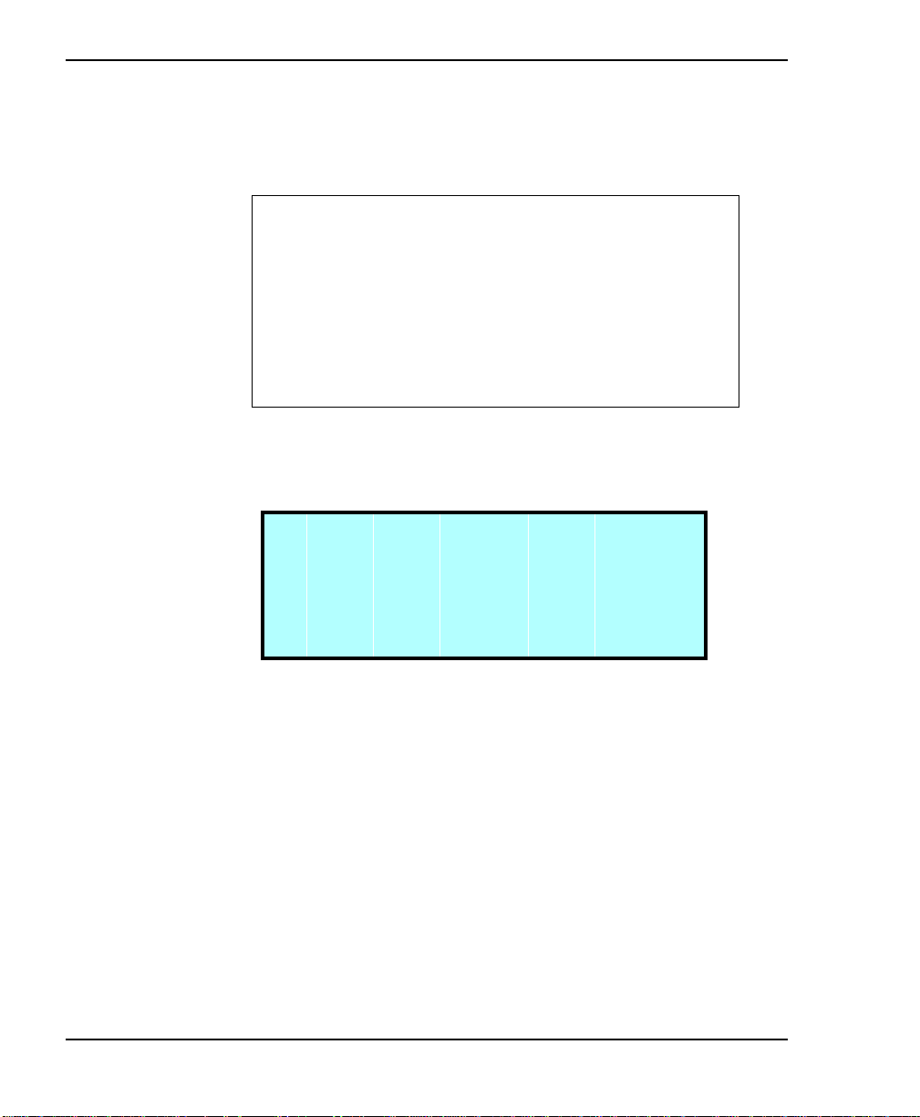
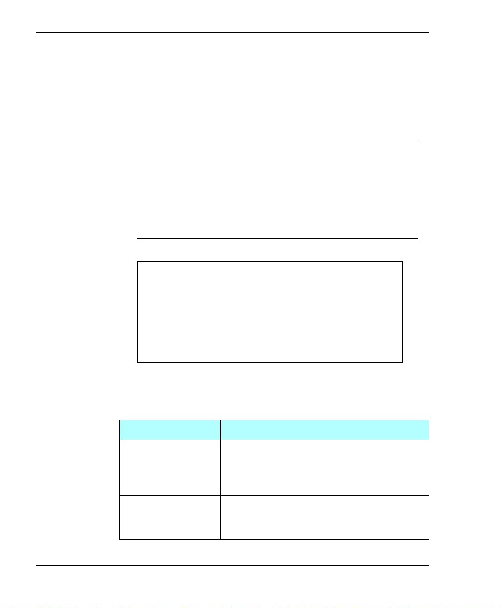
2. From the Configuration Menu select Set Max Addr Elem and
press
S e t M a x A d d r
. The following screen appears:
>(QWHU@
64
E l e m e n t : 0 0 0 0 0 0
↑
In the example above, xx is the current setting for the
Maximum Addressable Element option.
3. Use the
digit you wa nt to change. Then use the
>@
and
keys to move the screen arrow under the
>@
or
>@
>@
the selected digit.
Exabyte 440 and Exabyte 480
x x
→
keys to change
Page 79

Configuration
Note: If you set this option to a number higher than the
number of cartridge slots physically present, the
library automatically sets the Maximum Addressable
Element to the highest slot number that can store a
cartridge. For example, if you have an Exabyte 440
libra ry and you set the Maximum Addres sable
Element option to 60, the library changes the setting
to 40 because slot 40 is the highest slot number that can
store a cartridge.
4. Press >(QWHU@. The library prompts you for confirmation. If the
number is co rrect, press >(QWHU@.
Installation and Operation
65
Page 80

Chapter 3
Use Mammoth
The Us e Mam moth opt ion co nfig ures the li bra ry t o comm unic ate
proper ly w ith the ins tall ed tape driv e. When Us e Mammo th is on,
the li brary configu res to com municat e with an Ex abyte Ma mmoth
tape drive. When Use Mammoth is off, the library configures to
communicate with a non-Mammoth tape drive.
➤ Important I f you want to upgra de to Ma mmoth
tape drives, you must obtain an upgrade kit from
Exabyte.
To view the tap e drive model:
1. From the Configuration Menu, select Use Mammoth.
66
S e t T i m e
S e t S e c u r i t y O N
S e t S e r i a l N u m b e r
U s e M a m m o t h O F F
→
2. Press and 0 to toggle Use Mammoth on and off.
3. Press
>(VFDSH@
to return to the Main Menu.
↑
➤ Important If you are using Eliant 820 or
Exabyte 8505XL tape drives, make sure the Use
Mammoth option is OFF. If Use Mammo th is ON,
you may not be able to read or write data.
Exabyte 440 and Exabyte 480
Page 81

Setting robot control modes
To determine which interface will control CHM motion, you can
set the library to one of the following control modes:
SCSI Interface
LCD Interface
25-Pin or 9-Pin (narrow libraries)
25/9-Pin (wide libraries)
These control modes allow you to operate the library with the
application software (SCSI Interface) or perform diagnostic
functions on the library (LCD Interface, 25-Pin, 9-Pin, 25/9-Pin).
Refer to the following section for control mode descriptions. Refer
to page 69 for instructions about changing the control mode.
Note: Control mode settings remain through power cycles.
Configuration
SCSI Interface mode
In SCSI Interface mode, your application software controls the
motion of the CHM by issuing SCSI commands across the SCSI
bus attached to the library .
Note: The applica tion software can issue comman ds to the
For detailed inform ation about the SCSI commands supported by
the Exabyte 440 and Exabyte 480, refer to the EXB-440 and EXB-480
8mm Libraries SCSI Reference.
Installation and Operation
library regardless of the control mode. However, the
library must be in SCSI Interface mode for the software to
control the motion of the CHM.
67
Page 82

Chapter 3
LCD Interface mode
When the library is operating in LCD In terface mode, yo u can
control the motions of the CHM from the operator panel.
Note: You can use many operator panel features without
changing to LCD Interface mode. LCD Interface mode is
required only when you want to control the motions of
the CHM from the operator panel.
9-Pin and 25-Pi n Port mo des or
25/9 Pin mode
When the library is operating in a serial port mode (9-Pin or 25-Pin
Port mode for narrow libraries; 25/9 Pin Port mode for wide
libraries), you can control the motions of the CHM from a remote
console program connected to the library’s 9-pin or 25-pin port.
68
Note: Use the 9-Pin, 25-Pin, or 25/9 Pin mode to control CHM
motion only. You do not need to change the control mode
to access a tape drive’s serial p ort.
Exabyte 440 and Exabyte 480
Page 83

Configuration
Changing the control mode
1. Make sure the library is in the ready state (for example, no
hardware errors, the door is closed, and so on).
2. If security has been enabled, disable it. See page 60.
3. From the Main Menu, select Interface Menu.
4. From the Interface Menu, select Control Mode Menu.
5. Select the desired control mode. The current control mode is
indicated with an asterisk (*).
➤ Important Whe n the l ibra ry is in LCD I nte rface
mode or in one of the serial port modes, the
software application canno t control the CHM .
6. When the library displays a confirmation message that it has
chan ged the control mode, press
Interface Menu, and
Installation and Operation
>(VFDSH@
>(VFDSH@
again to return to the Main Menu.
to return to the
69
Page 84

Chapter 3
Checking the setup
After installing the hardware and software, check the setup by
performing some exercises on the library. (While these exercises
are not required, it is a good idea to verify that your software and
hardware are communicating properly before you begin
operations.)
Use the options on the Diagnostic Menu to exercise the
hardware. This determines whether the library hardware
components are operating properly. See Chapter 7 for
instructions.
Instruct the application software to load some cartridges into
each tape drive. This determines wheth er the software and
library are communicating pr ope rly.
Back up several megabytes of data to each tape drive and
perform a comparison check on the backed up data. This
determines whether the software and tape drives are
communicating properly.
70
If problems occur...
If the library and tape drives are
not operating as expecte d
If there i s an e rror code dis playe d
on the LCD
If you cannot solve the problem
yourself
See Chapter 8 for
troubleshooting information.
See Appe ndix C for a lis t of error
codes and corrective actions.
C onta ct your se rvic e provi der or
Exabyte.
Exabyte 440 and Exabyte 480
Page 85

4Library Operation
Once the library and application software are installed and
configured, you can automatically perform backup and restore
operations using the software. You should not need to intervene
in the cartridge processing during normal library operations.
This chapter describes library operations that you m a y
occasionally need to perform:
Selecting and replacing data cart ridges
Resetting the library
Selecting and replacing data cartridges
This section describes how to:
Select the appropriate data cartridges for your tape drive
Replace a single cartridge
Replace the cartridge magazines
Store data cartridges when not in the library
Installation and Operation
71
Page 86
Chapter 4
Selecting data cartridges
Always us e Exabyte media to achieve the best tape drive
performance. Tape drives are tested to specifications using
Exabyte media at the factory.
➤ Important B eca use of media mana gement a nd
application software issues, Exabyte recommends
that you do not mix AME and MP data cartridges
in the same library. If you must mix AME and MP
cartridge s, contact your application software
vendor.
CAUTION
Never use video-grade tape for data storage.
Video-grade tape can be less accurate than
data-grade tape and is more abrasive to tape
drive recording heads.
72
The following table lists the data cartridges to use with the type
of tape drive installed in your library.
Tape drive model Compatible data cartridges
Exabyte Mammoth Exatape Advanced Metal Evaporated (AME)
Data Ca rtridges, in lengths of 22m and 170m.
Exabyte Mammoth can read, but not write,
MP data cartridges.
Eliant 820 Exatape 8mm Metal Particle (MP) Data
Ca rtridges, in lengths of 15m, 54m, 112m, or
160m XL.
Exabyte 440 and Exabyte 480
Page 87

Library Operation
Replacing a sing le cartridge
A s describ ed in this section, you can use several diff erent methods
to replace single cartridges without opening the library door.
Use the Extend/Retract E/E option to insert or remove
cartridges through the en try/exit port.
Use the Remove Cartridge option to remove the cartridge.
Use the Insert Cartridge option to replace the cartridge.
➤ Important Do not open the library door to
repla c e i ndividua l ca rtridge s . O pe ning a nd clos ing
the library door causes the library to u pdate the
ca rtridge inve ntory, whic h tak es a pproximate ly 2½
to 5 minutes.
Using the Extend/Retract E/E option
1. Make sure that security is disabl ed (see page 60).
2. From the Main Menu, select Extend/Retract E/E. The library
extends or retracts the entry/exit port transport arm,
depending on its current position.
3. Insert the cartridge into the entry/exit por t and press
remove a cartridge by pressing down on the entry/exit port
PUSH tab, as shown in the following figures.
Installation and Operation
>(QWHU@
; or,
73
Page 88
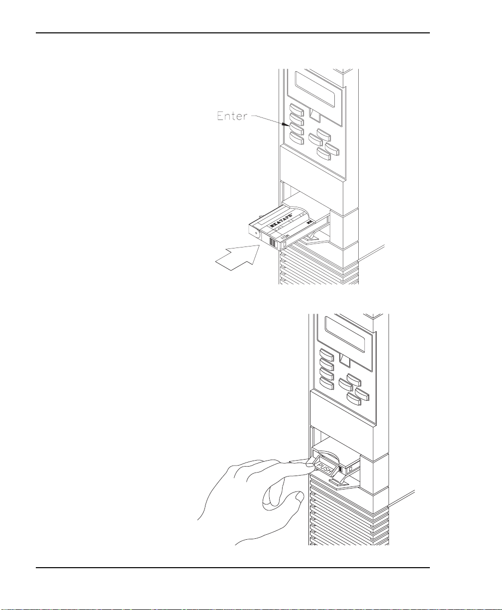
Chapter 4
pg 68 figure link
74
Exabyte 440 and Exabyte 480
Page 89

Library Operation
Using the Remove Cartridge option
1. Make sure security is disa b led (see page 60).
2. Change to LCD Inte rface con trol mode (see page 67).
3. From the Main Menu, select Maintenance Menu.
4. From the Maintenance Menu, select Remove Cartridge. The
following screen appears:
S e t S o u r c e 0
5. Press
the slot or tape drive where the cartridge is located). For more
information abo ut element index es, see Appendix D.
6. Press
transport arm, and the transport arm extends to the entry/exit
port. The library displays a screen similar to the following (the
source index may be different):
R e m o v e 0→E / E
7. Press down on the entry/exit port PUSH tab and remove the
cartridge (see the second figure on page 74).
Installation and Operation
or
>@
>(QWHU@
to set the source element index (the index of
>@
. The CHM moves the cartridge to the entry/exit
P r e s s E N T E R t o
R e t r a c t E / E
75
Page 90
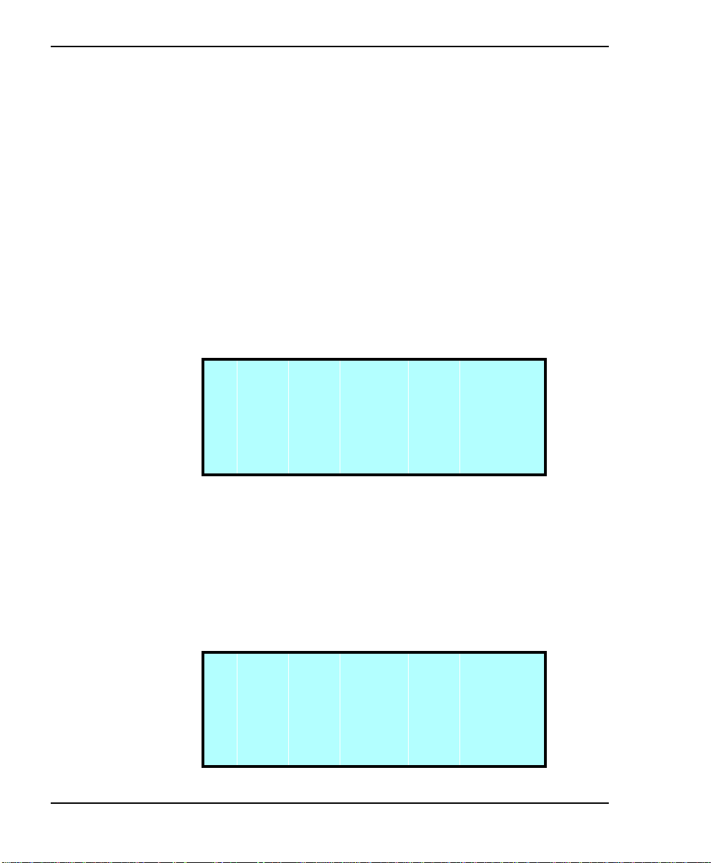
Chapter 4
8. Press >(QWHU@to retrac t the entry/exit transport arm.
9. Press >(VFDSH@ to return to the Maintenance Menu.
Using the Insert Cartridge option
1. Make sure security is disa b led (see page 60).
2. Change to LCD Inte rface con trol mode (see page 67).
3. From the Main Menu, select Maintenance Menu.
4. From the Maintenance Menu, select Insert Cartridge. The
library displays the following screen:
S e t D e s t i n a t i o n 0
I n c r e a s e
↑
D e c r e a s e
↓
76
5. Press
>@
or
to set the destination element index (the index
>@
of the slot or d r ive i n w hi c h yo u wa nt to pl a c e t he ca r t r idge).
For more information about element indexes, see
Appendix D.
6. Press
. If the location is a ta pe dr ive, the library displa y s
>(QWHU@
the following prompt:
S h o u l d t h e c a r t r i d g e
b e l o a d e d i n t o
t h e d r i v e ? N O
Exabyte 440 and Exabyte 480
→
Page 91

Library Operation
7. If you want to load the cartr i dge i nto the tape driv e, press >@
to select YES and press >(QWHU@. The library displays the
following prompt:
S h o u l d t h e
c a r t r i d g e b e
s c a n n e d ? Y E S
←
8. If you do not want to scan the bar code label on the cartridge,
press >@ to select NO and press >(QWHU@. The library displays a
screen similar to the following (the destination index may be
different):
I N S E R T E / E→8 3
P r e s s E N T E R t o
R e t r a c t E / E
9. Insert the cartridge in the entry/exit port with the cartridge
door flap to the left and press
(see the second figure on
>(QWHU@
page 74).
10. Press
>(VFDSH@
to return to the Maintenance Menu.
Installation and Operation
77
Page 92

Chapter 4
St oring data cartridges
To maxi mize the shelf life of your data cartri dges and ensure data
integrity, follow the guidelines below when storing cartridges.
Store cartridges in a suitable environment. Follow the
specifications for storage temperature and other
environmental requirements, as described on the cartridge
packaging. Do not al low the temperature and humidity in the
storage environment to fluctuate.
Keep the storage area as free of airborne particulates as
possible. To elimi nate obvious s ources of parti cul ates, do not
permit anyone to smoke, eat, or drink near the storage area,
and do not store cartridges near a copier or pr inter that may
emit toner and paper dust.
Store cartridges as soon as possible after you remove them
from the library. Immediate storage helps avoid many of the
conditions that can damage tapes, such as temperature and
humidity fluctu ation, particulate contamination, and
excessive handling.
78
Store cartridges with the write-protect switch in the
protected position (the red switch is fully visible).
If possible, store data cartridges in a cartridge magazine. In
the cartridge magaz ine, cartrid ges are protected from airborne
contaminants by a clear plastic cover. With the cover in place,
the magazines can be stacked on top of each other to make the
most efficient use of storage space.
Exabyte 440 and Exabyte 480
Page 93
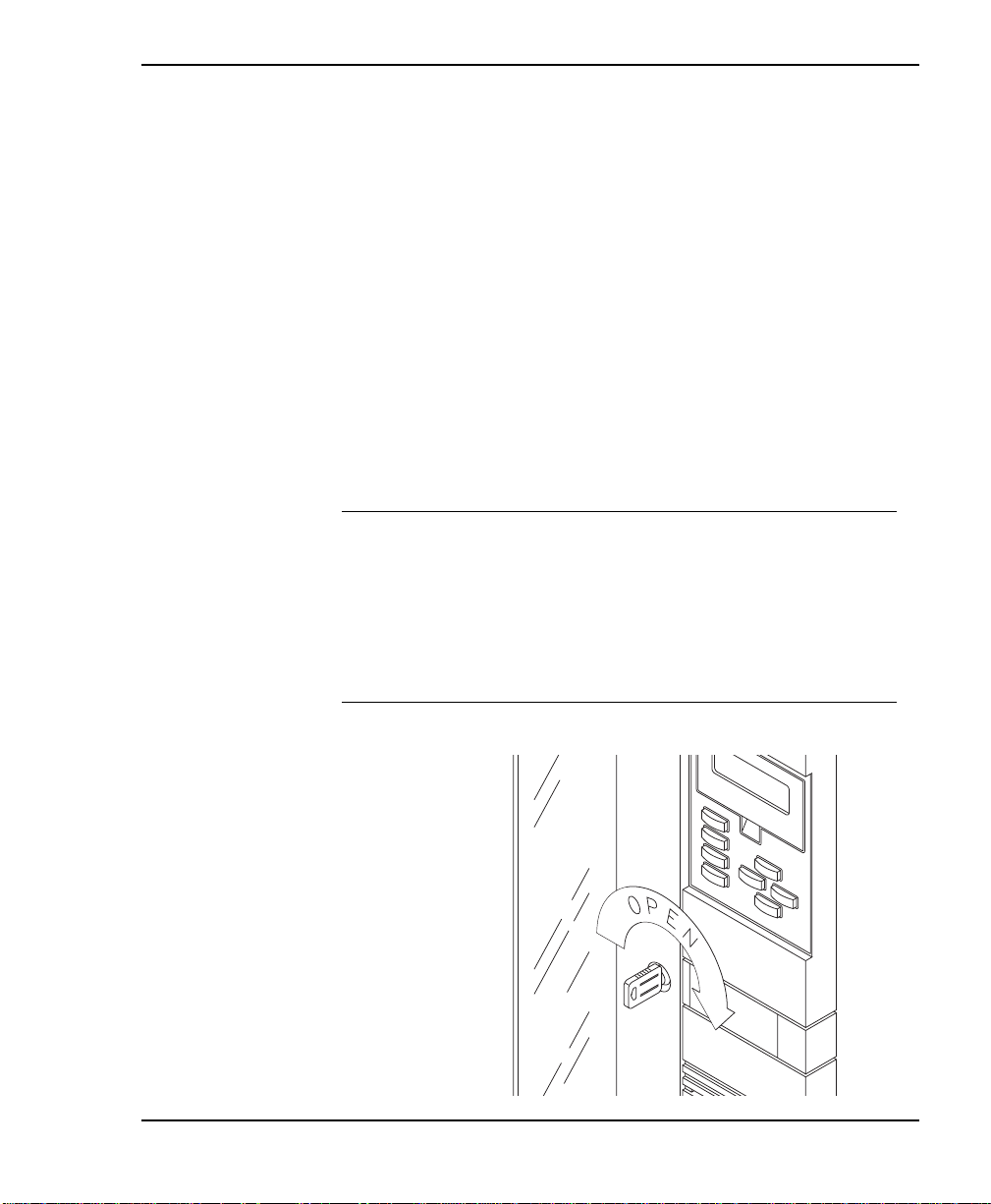
Replacing the cartridge magazines
To open the door and replace a data cartridge magazine:
1. Insert the key in the lock, pus h in, and turn it one quarter turn
to the right, as shown in the following figure. When you
unlock the door:
Th e library completes its current operation, moves the
CHM to the home position at the bottom of the long axis,
rotates the drum assembl y to the home position, and turns
off curre nt to all mo tors.
Th e in terlock me chanism releases.
➤ Important D o not open the libra ry door unle ss
you need to remove and replace cartridge
maga zines or perform a mai nte na nce operation. I t
ta k es 2½ to 5 minutes for the li brary to upda te the
cartridge inventory after the door is opened and
closed.
Library Operation
Installation and Operation
79
Page 94

Chapter 4
2. When the door’s interlock mechanism releas es, open the door.
CAUTION
Do not force the door open. The door’s
interlock mechanism may be prevented from
rele as ing by L CD se cu rity or by the a pplic a tion
software.
3. Make sure the CHM and its cabling are safely out of the way
of the magazines. If necessary, mo ve the CHM to the bottom
of the lo ng axis by pushing firmly against its base.
4. If necessary, manuall y rotat e the drum assembl y to acces s the
cartridge magazine you want to remove.
5. Grasp the cartridge magazine on either side, pull it out first
from the top, then the bottom.
80
Exabyte 440 and Exabyte 480
Page 95
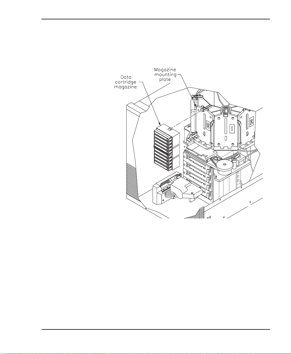
Library Operation
6. If desired, replace the magazine by positioning it over the
mounting plate with the single mounting guide toward the
top.
7. Insert the bottom of the magazine first, then snap the
magazine in to place by pressing against the top.
8. Close the door and lock it by tur ning the key a quarter turn to
the left. After the door is closed:
Installation and Operation
The library performs its power-on self-test.
The library returns Unit Attention status to the host.
The software may update its own cartr idg e inventory.
81
Page 96

Chapter 4
Resetting the library
If the libra ry has encountered an error and is still not operating
after you have tried the corrective action for the error, you may
need to reset the library. A reset causes the library and the tape
drives to perform their power-on self tests. Unless configured
otherw ise, ta pe drives will rewind the tape after a reset, but will
not eject the data cartridge.
Note: If the library is performing a cartridge move operation
when it is reset, it completes the move operation before it
performs the power-on self-test.
B ef ore re s e tting the l ibra ry, mak e s ure the library
or tape drives are not communicating across the
SCSI bus. Resetting the li brary and tape drives
may disrupt communications on th e SCSI bus.
CAUTION
82
To reset the library, you can use one of the following methods:
Press
confirmation screen (or press
Perform a power-on reset by powering the library off, then
back on.
Perform a remote hardware reset by plugging a cable into the
remote reset port on the back of the library and press a reset
button on the cable. (See Appendix A for more information.)
Note: The lib r ar y , t ap e dr i v es , or the enti r e SC S I b us c a n al s o b e
automatically reset by the host.
When the librar y is res et, both the libr ary and tape drives perf orm
power-on self-tests. Then the Main Screen appears on the LCD.
on the operator panel, then press
>5HVHW@
>(VFDSH@
Exabyte 440 and Exabyte 480
to cancel).
>(QWHU@
at the
Page 97

5Tape Drive Operation
The application software automatically controls the tape drives to
perform backup and restore operations. You do not need to
inter ve ne i n the ca r tr i dg e p r oc ess ing; howev er , yo u m a y need to
perform the following tasks:
Monitoring the tape drive LEDs
Cleaning the tape drives
Displaying infor mation about ta pe drives
Ejecting a cartridge manually
Note: You cannot control the tape drives from the operator
panel. However, you can perform diagnostic s on the tape
drives across the 9-pin or 25-pin serial port. (See Chapter 7
for information about diagnostics.)
Installation and Operation
83
Page 98
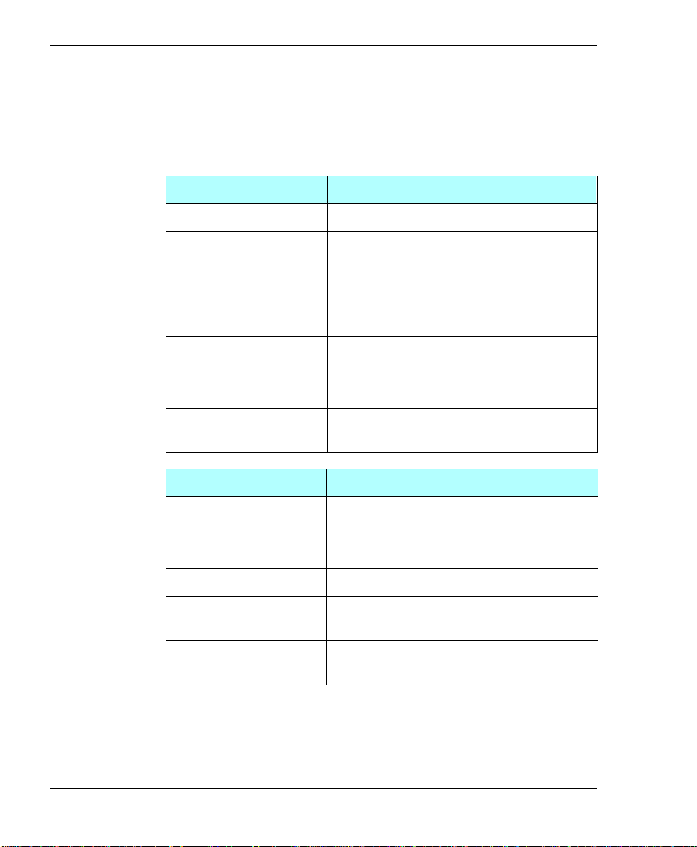
Chapter 5
Monitoring the t ape drive LEDs
The following tables show the tape drive LED states and the
conditions they indicate.
Eliant 820 LED state Condition
All LEDs on Power-on self-test.
Top and bottom LEDs
flashing (middle LED
may be flashing)
Top LED flashing
(bottom LED off)
Middle LED flashing SCSI bus activity.
Bottom LED on A tape is loaded, and the tape drive is
Bottom LED flashing
(top LED off)
Mammoth LED state Condition
All LEDs on The tape drive was reset or it is
Top LED on Cleaning required.
Top LED flashing Hardware error.
Middle LED on A tape is loaded, and the tape drive is
Cleaning required.
Hardware error.
ready to perform tape motion activities.
Tape motion. A fast flash indicates
high-speed tape motion.
performing its power-on self-test.
ready to perform tape motion a ctivities.
84
Bottom LED flashing Ta pe motion. A fast flash indicates
high-speed tape motion.
Note: You may observe other LED activity (random flashing,
steady on, and so on). For a detailed description, refer to
the product specification for your library.
Exabyte 440 and Exabyte 480
Page 99

Cleaning the tape drives
You should clean a tape drive whenever the library displays
“Drive needs cleaning” on the Main Screen of the LCD or
whenever your application software notifies you. (Not all
software applica tions display cleaning requir ements.) Regular
cleaning helps ensure that the tape drives function reliably.
Note: Some a ppli cati ons moni tor t he tape dr ives ’ cl eaning ne eds
and automatical ly insert the cleaning cartridg e in the drive
whenever i t needs c leaning . If thi s is the case , you can s kip
the cleaning in structions in this section.
Selecting cleaning c artridges
If you are using Exabyte Mammoth tape drives, use an Exabyte
Mammoth Clean ing Cartridge or a c leaning cartridge approved
by Exabyte for use with Mammoth.
Tape Drive Operation
If you are using Eliant 820 tape drives, use an Exabyte Premiu m
8mm Cleaning Cartridge, or a cleaning cartridge approved by
Exabyte for use with the Eliant 820 tape drive.
To order cleaning cartridges, contact Exabyte (see pag e 10).
Installation and Operation
CAUTION
Use only cleaning cartridges approved by
E xabyte for your tape drive . Us ing cloth s wabs ,
cotton swabs, cleaning agents, or cleaning
cartridges not approved by Exabyte may void
the tape drive warranty.
85
Page 100

Chapter 5
Cleanin g the tape drives from the operator panel
To clean the tape drives from the operator panel:
1. Determi ne which d riv e needs c leani ng by l ook ing at the dri ve
LEDs. For Ma mmoth tape drives, the top LED turns on when
cleaning is required. For Eliant 820 tape drives, the top and
bottom LEDs flash rapidly. (Depending on SCSI bus activity,
the middle LED may also be flashing.)
Note: When you insert an AM E ca rtridge into an Exab yt e
Mammoth tape drive after reading MP tape, the top
LED illuminates and the cartridge is ejected. Before
you can use the AME cartridge, you must clean the
tape drive.
2. Make sure you have a cleaning cartridge i n the fixed car tridge
slot. If the fix ed cartridg e slot contains a data car tridge instead
of a cleaning cartridge, the tape drive will not be cleaned and
you will have to manually eject the da ta cartridge from the
tape drive (see page 92).
86
If ther e i s no cl ea ni ng c a rt ri d g e i n the f i x ed ca r tr i d ge s l ot, u s e
the Insert Cartridge option on the Maintenance Menu to insert
a cleaning cartridge into the library’s fixed cartridge slot (see
page 76).
3. If secu rity has been enable, disable it (see page 60).
4. Change to LCD Inte rface con trol mode (see page 67).
5. From the Main Menu, select Maintenance Menu. Then select
the Clean Drives Menu.
Exabyte 440 and Exabyte 480
 Loading...