

Page 1
User’s Manual
Version 1.00 - February 2011
Fill and Key Playout Server
Page 2

Page 3

GX ser ver – Version 1.0 – User’s Manual
EVS Br oadcast Equipment – February 2011
Issue 1.0.C
I
COPYRIGHT
EVS Broadc ast Equipment – Copyright © 2011. All rights reserved.
DISCLAIMER
The information in this manual is furnished for informational use only and subject
to change without notice. While every effort has been made to ensure that the
information contained in this user manual is accurate, up-to-date and reliable,
EVS Broadcast Equipment cannot be held responsible for inaccuracies or errors
that may appear in this publication.
IMPROVEMENT REQUESTS
Your comments will help us improve the quality of the user documentation. Do not
hesitate to send improvement requests, or report any error or inaccuracy on this
user manual by e-mail to
doc@evs.tv.
REGIONAL CONTACTS
The address and phone number of the EVS headquarters can be found by clicking
the icon in the user interface.
You will find the full list of addresses and phone numbers of local offices on the
EVS website on the following pag e:
http://www.evs.tv/contacts
USER MANUALS ON EVS WEBSITE
The latest version of the user manual, if any, and other user manuals on EVS
products can be found on the EVS download center, on the following webpage:
http://www.evs.tv/downloadcenter
Page 4

Issue 1.0.C
GX ser ver – Version 1.0 – User’s Manual
EVS Br oadcast Equipment – February 2011
II
Page 5

GX ser ver – Version 1.0 – User’s Manual
EVS Br oadcast Equipment – February 2011
Issue 1.0.C
III
Table of Contents
TABLE OF CONTENTS ................................................................................................. III
1. INTRODUCTION ..................................................................................................... 1
1.1 GX SERVER PRESENTATION ............................................................................................... 1
1.1.1 General Descript ion....................................................................................................... 1
1.1.2 General Architect ure and W ork f low ................................................................................ 1
2. GX SERVER OVERVIEW ....................................................................................... 3
2.1 CHAPTER OVER VI EW ........................................................................................................... 3
2.2 HARDWARE COMPONENTS ................................................................................................. 4
2.2.1 Hardware Specif ic at ions ................................................................................................ 4
2.2.2 Chassis ......................................................................................................................... 4
2.2.3 Front Panel ................................................................................................................... 6
2.2.4 Rear Panel .................................................................................................................... 6
2.2.5 Safety, Complianc e, and Operat ing C ondit ions ............................................................... 7
2.3 SERVER MAI N SPEC I FIC ATIONS .......................................................................................... 9
2.3.1 Input Files ..................................................................................................................... 9
2.3.2 GX Clips ....................................................................................................................... 9
2.3.3 Supported Video Standards ........................................................................................... 9
2.3.4 Controller .................................................................................................................... 10
2.4 CLIENT CONTRO L PC ......................................................................................................... 10
3. GX SERVER SETUP .............................................................................................11
3.1 CHAPTER OVER VI EW ......................................................................................................... 11
3.2 CABLING .............................................................................................................................. 11
3.3 INSTALLATION .................................................................................................................... 13
3.3.1 GX Server Inst allat ion and Ghos t R estore .................................................................... 13
3.3.2 Switching on v ers us Starting t he Serv er ....................................................................... 13
4. GX WEB INTERFACE ...........................................................................................14
4.1 CHAPTER OVER VI EW ......................................................................................................... 14
4.2 SERVER CONFIGURATION AND ST AR T ............................................................................. 15
4.2.1 Access ing t he GX Server f rom a Rem ot e PC ............................................................... 15
4.2.2 Server Control W indow ................................................................................................ 16
4.2.3 Server Settings ........................................................................................................... 16
4.2.4 Server Status I nf orm ation ............................................................................................ 18
4.2.5 Starting the GX ser v er ................................................................................................. 19
4.3 OVERVIEW ON MAIN WINDOW ........................................................................................... 20
4.3.1 Introduction ................................................................................................................. 20
4.3.2 Import Area ................................................................................................................. 21
4.3.3 Manage Area .............................................................................................................. 22
4.3.4 Server Control But t on .................................................................................................. 23
4.3.5 Rules for R ow Select ion .............................................................................................. 24
Page 6

Issue 1.0.C
GX ser ver – Version 1.0 – User’s Manual
EVS Br oadcast Equipment – February 2011
IV
5. OPERATION ..........................................................................................................25
5.1 CHAPTER OVER VI EW ......................................................................................................... 25
5.2 MANAGING DRIVES AND FOLDERS ................................................................................... 27
5.2.1 Drive Tree St ruc t ure .................................................................................................... 27
5.2.2 Drive Display ............................................................................................................... 27
5.2.3 How to Display Folder Structure and Source F iles ........................................................ 27
5.2.4 How to Connect and Disconnect a Network Drive ......................................................... 28
5.3 SELE CTING AND IMPO RTING SOURCE FIL E S ................................................................... 29
5.3.1 Source File List ........................................................................................................... 29
5.3.2 Fields in the Sourc e F ile List ........................................................................................ 29
5.3.3 How to Import Files on t he GX Serv er .......................................................................... 30
5.3.4 Import Results ............................................................................................................. 32
5.3.5 Display of Import ed Elem ent s on the Us er Interf ac e ..................................................... 32
5.3.6 Raw Materia l s Ta b ...................................................................................................... 33
5.3.7 Fields in the R aw Mat erials Tab ................................................................................... 34
5.3.8 Deleting a File from the Raw Materials Drive ................................................................ 35
5.4 MANAGING GX CLIPS ......................................................................................................... 37
5.4.1 GX Clips Tab .............................................................................................................. 37
5.4.2 Fields in the GX C lips Tab ........................................................................................... 37
5.4.3 Switching GX C lips Online or Of f line ............................................................................ 39
5.4.4 Deleting GX Clips ........................................................................................................ 41
5.5 PREPARIN G GX C LI PS F OR PLAYOU T ............................................................................... 42
5.5.1 Edit GX Clip Window ................................................................................................... 42
5.5.2 Editing GX Clips Param et ers ....................................................................................... 44
5.5.3 General Principles About T C F ields on the GX Serv er .................................................. 47
5.5.4 General Settings in t he Edit GX Cl ips W indow .............................................................. 47
5.5.5 Video Settings in t he Edit GX C lips Window ................................................................. 49
5.5.6 Audio Settings in t he Edit GX C lips Window ................................................................. 51
5.5.7 Clip Preview in t he Edit GX Clip Window ...................................................................... 54
5.5.8 Command Buttons in the Edit GX Clip Window............................................................. 56
5.5.9 GX Clip Duration and T im ec odes ................................................................................. 57
GLOSSARY ....................................................................................................................59
Page 7
GX ser ver – Version 1.0 – User’s Manual
EVS Br oadcast Equipment – February 2011
Issue 1.0.C
1
1. Introduction
1.1 GX SERVER PRESENTATION
1.1.1 GENERAL DESCRIPTION
The GX server is a 1U H D/SD f ill and key playout s erver.
The source graphic and audio files can be imported from the built-in DVD drive,
via the USB or eSata ports on the GX server, or via an Ethernet connection to a
PC. They will be imported in their orig inal format, then transcoded into GX clips on
the GX s erver.
The GX clips can be published to an external control device through a standard
protocol like VDCP, and be played back under the control of these protocols on 2
SDI outputs (key and fill).
The GX server allows the synchronized playout of uncompressed fill and key GX
files, and embedded audio. The server is able to handle separate video nested
loops, with user-defined loop points.
1.1.2 GENERAL ARCHITECTURE AND WORKFLOW
SCHEMA
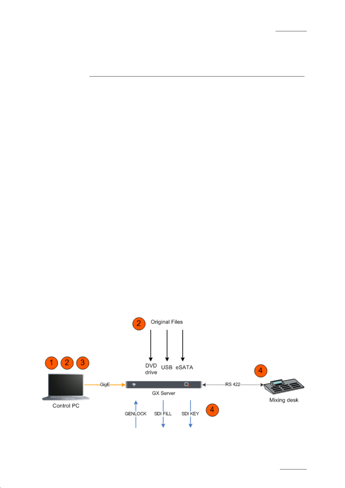
The following schema provides an overview on the system architecture and
general workflow for t he import of original files, the creat ion and the playout of G X
clips on the GX server. The schema is described below.
Page 8
Issue 1.0.C
GX ser ver – Version 1.0 – User’s Manual
EVS Br oadcast Equipment – February 2011
2
transcode operations are not
DESCRIPTION
When the GX server is switched on, the users can control the GX server from a
remote PC via a web-based application using a loc al network connection.
1. Users c onfigure the server param et ers from the web interface on t he client PC.
2. Users import the original files (fill and key, audio) to the Raw Materials drive
(internal HDD drive) using one of the following methods:
o Web interface on the client PC
o DVD drive on the GX server
o USB or eSATA connectors on the GX server
3. Users associate the original files, define synchronization parameters, and
upload them (switch them online) as GX clips onto the GX Clips drive (Solid
St at e Dis k dr ive) .
The files are then ready for playout.
4. When users start the GX server from the web interface, the GX clips that
correspond to the requested video standard are published to the switcher.
The operator can then select the requested GX clips and play them out using
the switcher. The switcher and the G X server communicat e via a RS 422 link ,
by means of a control protocol like VDCP.
Important
The use of the web interface and the
possible while the GX server is started.
Page 9

GX ser ver – Version 1.0 – User’s Manual
EVS Br oadcast Equipment – February 2011
Issue 1.0.C
3
2. GX server Overview
2.1 CHAPTER O VERVIEW
What about … ? Section Page
Hardware Specifications 2.2.1 Page 4
Chassis 2.2.2 Page 4
Front Panel
Rear Panel 2.2.4 Page 6
Safety, Compliance, and Operating Conditions 2.2.5 Page 7
Input Video Sequences - Page 9
Input Audio Sequences - Page 9
GX Cli ps 2.3.2 Page 9
Supported Video Standards 2.3.3 Page 9
Controller 2.3.4 Page 10
2.2.3 Page 6
Page 10
Issue 1.0.C
GX ser ver – Version 1.0 – User’s Manual
4
2.2 HARDWARE COMPONENTS
2.2.1 HARDWARE SPECIFICATIONS
The following table gives an overview on the hardware specifications of the GX
server:
Component Specification
CPU Core i7
RAM 3 GB
EVS Br oadcast Equipment – February 2011
Hard disk drive
(Raw Mat er ials
drive)
Solid-state drive
(GX Clips dr ive)
Playout board PCX3
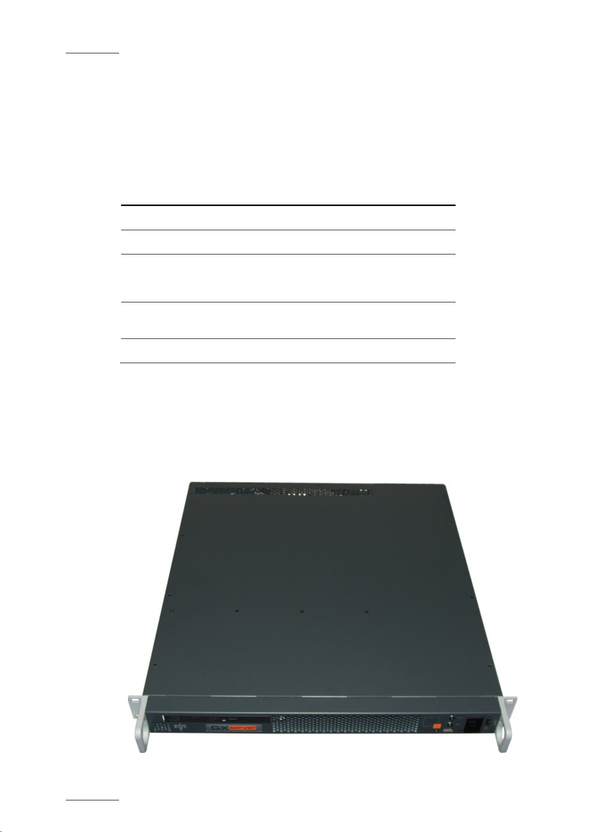
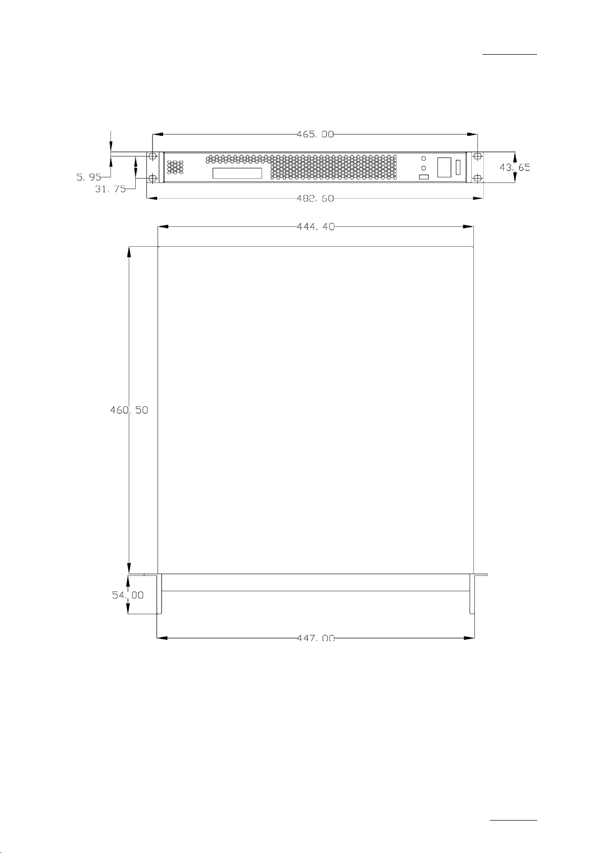
2.2.2 CHASSIS
The following picture shows the 1U GX server. The schemas below provide full
information on dimensions.
400GB SATA
2 x 128GB SSD
Page 11
GX ser ver – Version 1.0 – User’s Manual
EVS Br oadcast Equipment – February 2011
Issue 1.0.C
5
Page 12
Issue 1.0.C
GX ser ver – Version 1.0 – User’s Manual
6
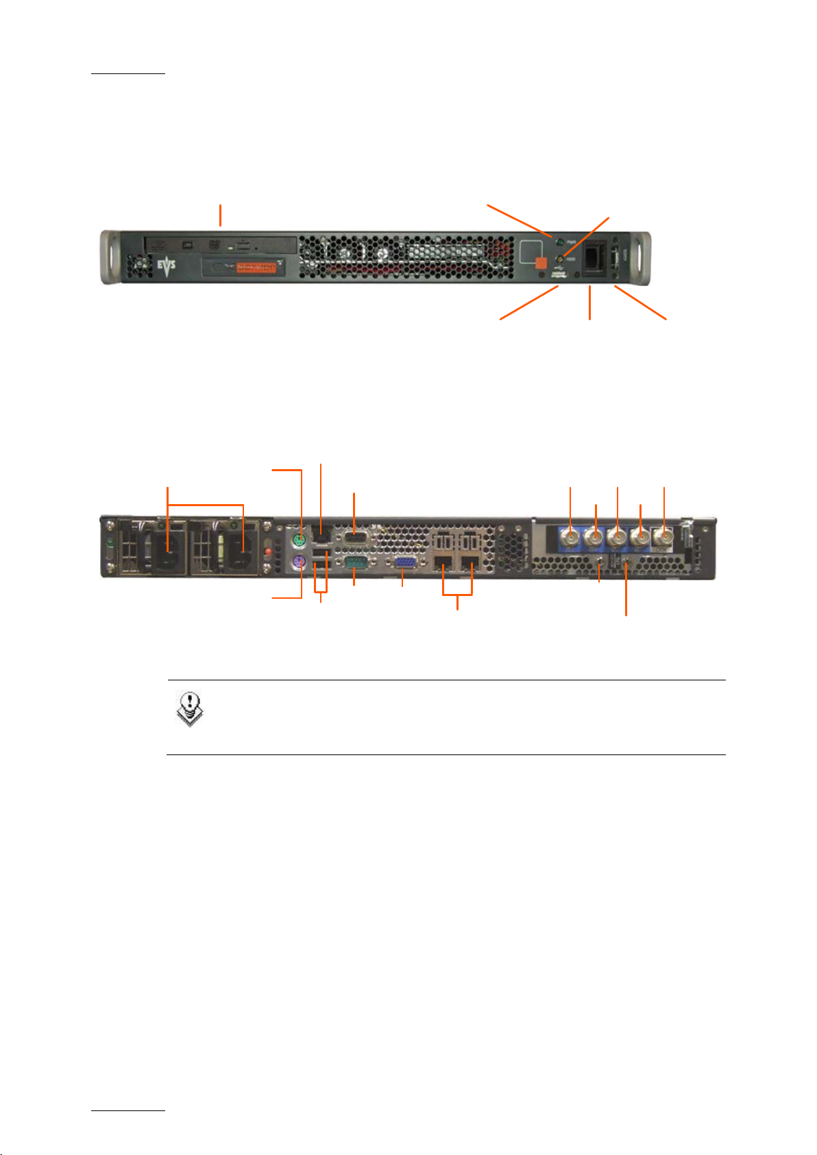
DVD Player
Server activity indicator
(orange HDD light)
Power indicator
(green PWR light)
USB
connector
Power
switch
eSata
connector
Fill
Mouse
connector
USB
Power
Supplies
Keyboard
connector
Key
N/A
N/A
Genlock
N/A
N/A
N/A
RS422
GigE
Ethernet
GigE
Ethernet
VGA
2.2.3 FRONT PANEL
2.2.4 REAR PANEL
EVS Br oadcast Equipment – February 2011
Note
The two connectors labeled IN1 and IN2 (on the right of the Fill and Key
connectors) are not currently used.
Page 13

GX ser ver – Version 1.0 – User’s Manual
EVS Br oadcast Equipment – February 2011
Issue 1.0.C
7
2.2.5 SAFETY, COMPLIANCE, AND OPERATING CONDITIONS
CE MARKING
The CE marking is affixed to indicate compliance with the following directives:
• 89/336//EEC of 3 May 1989 on the approximation of the laws of the Members
States to electromagnetic compatibility.
• 73/23/EEC of 19 February 1973 on the harmonization of the laws of the
Members States relating to electrical equipment designed for use within
certain voltage limits.
• 1999/5/EC of 9 March 1999 on radio equipment and telecommunications
terminal equipment and the mutual recognition of their conformity.
POWER SUPPLY
This equipment is equipped with AUTOSWITCH and hot-swappable power supply.
Connection to supply: Pluggable equipment Type A (EN60950 §1.2.5): Equipment
which is intended for connection to the building power supply wiring via a nonindustrial plug and socket-outlet or a non-industrial appliance coupler or both.
Correct mains polarity must always be observed. Do not use reversible power
plugs with this equipment.
Class of equipment: Class 1 equipment (EN60950 § 1.2.5): electric shock
protection by basic insulation and protective earth.
Rated voltage: 100 to 240Vac (single phase)
Rated frequen cy: 47-63 Hz
Related Current: 6 A (100 to 120 Vac range) 3 A ( 220 to 240 Vac range)
Input connector: CEE22/IEC 320 3-pin male receptacle
Important
The protective earth must be connected to the ground before powering
up the unit.
ENVIRONMENTAL CONDITIONS
Temperature: 0°C to + 50° C (32°F to 104°F) ambient with free air f low
Relative humidity: 0% to 90% (non-condensing)
Cooling requirements: For ced air cooling air flow from front to back
Handling/movement: Designed for fixed use when in operation
Storage and transportation temperature: 0°C to +70°C (32°F to 158°F)
Storage and transportation relative humidity: 0% to 9 0% ( non -condensing)
Page 14
Issue 1.0.C
GX ser ver – Version 1.0 – User’s Manual
EVS Br oadcast Equipment – February 2011
8
HOT-SWAPPABLE POWER SUPPLIES
Both power supplies are hot-swappable.
The second power supply should be connected to mains to allow automatic power
switching to t he second power supply in the event that the first one fails.
GROUNDING
Ensure the disk recorder unit is properly grounded at all times to avoid electrical
shock hazard.
VENTILATION & RACK MOUNTING
Adequat e ventilation is obviously required f or optimum perform ance. As a result of
this consideration, ensure no other equipment is located close to the mainframe.
Important
• Remember that fans are used to air cool the equipment and protect
it from overheating.
• Do not block fans intakes during operations.
Page 15

GX ser ver – Version 1.0 – User’s Manual
EVS Br oadcast Equipment – February 2011
Issue 1.0.C
9
2.3 SERVER MAIN SPECIFICATIONS
2.3.1 INPUT FILES
The original sequences are imported and stored onto the Raw Materials drive
(HDD).
INPUT VIDEO SEQUENCES
The following static files with embedded alpha channels are supported in release
1.0 of t he GX server:
• Combined f ill & key Targa seq uences, i.e. TGA files.
Uncompressed TGA files or RLE compressed TGA files are supported.
• Combined f ill & key Tiff seq uences, i.e. TIFF files.
Uncompressed TIFF files or LZW compressed TIFF files are supported.
The file format s that include several video f rames in a single file are currently not
supported.
INPUT AUDIO SEQUENCES
The supported input audio files are stereo WAV files of 16-bit depth, 48 KHz,
including from 2 to 16 channels.
2.3.2 GX CLIPS
The GX clips are created in the database. The A/V material is stored onto the GX
Clips drives (SSD):
• The internal video files are stored in internal uncompressed formats, in the
requested video standard.
• The internal audio files are in raw 24 bits samples (per channel) format. They
can contain up to 16 embedded audio channels.
2.3.3 SUPPORTED VIDEO STANDARDS
The fill & key GX clips must have been prepared in one of the video standards
described in the table below:
Num
Common
name
GX server
name
Frame rate
Field
rate
Resolution
0
1 SD PAL 625i50 25 fr/s 50 fl/s 720 x 576
SD NTSC
(DF or NDF)
525i60 29.97 fr/s 59.94 fl/s 720 x 480
Page 16

Issue 1.0.C
GX ser ver – Version 1.0 – User’s Manual
EVS Br oadcast Equipment – February 2011
10
Num
2 1080i60
3 1080i50 1080i50 25 fr/s 50 fl/s 1920 x 1080
4 720p60
5 720p50 720p50 50 fr/s 50 fl/s 1280 x 720
Common
name
(DF or ND F)
(DF or NDF)
2.3.4 CONTROLLER
The following communication protocols between the GX server and the switcher
are supported for playout:
• VDCP
GX server
name
1080i60 29.97 fr/s 59.94 fl/s 1920 x 1080
720p60 59.94 fr/s 59.94 fl/s 1280 x 720
Frame rate
Field
rate
Resolution
2.4 CLIENT CONTROL PC
The GX web interface is running on Microsoft Silverlight on the client PC. If the
Silverlight framework is not installed on the client PC, users are requested to
install it when they launch the GX web interface for the first time.
The system requirements for Microsoft Silverlight are the following on Windows or
Mac operating systems:
WINDOWS
• Operating System: Windows 7,Windows Vista; Windows XP Service Pack 2
• Intel® Pentium® III 450MHz or faster processor (or eq uivalent)
• 128MB of RAM
MAC OS
• Operating System: Apple Mac OS X 10.4.8 or above
• Intel Core™ Duo 1.83GHz or faster processor
• 128MB of RAM
Page 17
GX ser ver – Version 1.0 – User’s Manual
EVS Br oadcast Equipment – February 2011
Issue 1.0.C
11
from the GX web interface for the
communication between the GX server and the protocol client to be
3. GX Server Setup
3.1 CHAPTER O VERVIEW
What about … ? Section Page
Cabling 3.2 Page 11
GX Server Installation and Ghost Restore 3.3.1 Page 13
Switching on versus Starting the Server 3.3.2 Page 13
3.2 CABLING
The GX s erver has to be cabled as shown on the sc hema below to allow:
• Users to im port video sequences and aud io files and to create t he GX clips on
the s erver from the client PC.
• Operators to control the playout via the switcher.
Important
The GX server is connected to the protocol clients through the RS422
port. Once the GX clips are ready for playout, the GX server however
needs to be manually started
established.
For more information on starting the GX server, refer to the sections
3.3.2 ‘Switching on versus Starting the Server’, on page 13 and 4.2.5
‘Starting t he GX server’, on page 19.
Page 18
Issue 1.0.C
GX ser ver – Version 1.0 – User’s Manual
EVS Br oadcast Equipment – February 2011
12
video equipment that will
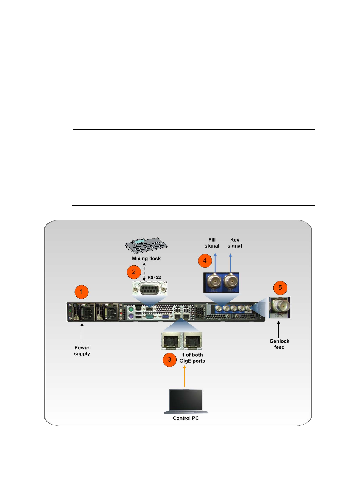
The schema below shows how the GX server needs to be cabled before switching
it on. The table hereafter briefly describes the connections highlighted on the
schema:
# Description
1. Connect the power supply t o mains.
Connect the second power s upply to allow automat ic power switching in case
of failure.
2. Connect t he VDCP client to the RS422 port on the GX server.
3. Connect the GX server to the loc al area net work via one of the GigE ports.
This will allow users to connect remotely to the GX server via the GX web
interface.
4.
Connect the KEY and FILL connectors to the
perform the keying of the GX outputs.
5.
Connect the Genlock feed to the GLK connector to make sure the video
signals from t he GX server are s ynchronized in your setup.
The mouse, keyboard and VGA connectors at the back of the server also allow
users to d irectly connect to t he server, mainly to per form tests and c hecks.
Page 19

GX ser ver – Version 1.0 – User’s Manual
EVS Br oadcast Equipment – February 2011
Issue 1.0.C
13
3.3 INSTALLATION
3.3.1 GX SERVER INS TALLATION AND GHOST RESTORE
The EVS staff will perform the initial installation of the GX server before the
server is d elivered.
When the server is installed, a g host image of the installed GX ser ver is created in
the Restor e folder (R: drive).
If you need to restore the ghost, please contact EVS support.
3.3.2 SWITCHING ON VERSUS STARTING THE SERVER
When the server is properly cabled, you switc h it on using the power switch on the
front panel. Switching on the s erver does not mean starting the server.
Once the server is switched on, you still need to start it to allow external
controllers to connec t to the GX server and to access the GX clips for playout. For
more information, refer to the section 4.2.5 ‘St art ing the GX server’, on page 19.
Before you can start the server, you need t o make sure that:
• The server is proper ly configured for t he external controllers to acc ess the GX
clips.
• The GX clips have been created on the GX server, and are online, ready for
playout.
All these steps are covered in the Installation and Operation sections.
Page 20

Issue 1.0.C
GX ser ver – Version 1.0 – User’s Manual
14
4. GX Web Interface
4.1 CHAPTER O VERVIEW
A dedicated web application, called the ‘GX web application’, makes it possible
create and prepare the GX clips from a remote PC. Then you can upload the GX
clips on the GX server, and eventually start the GX server.
This chapter gives an overview on the user interface of the web application, and
on the general workflow you will follow. It contains the following sections:
What about … ? Section Page
Accessing the GX Server from a Remote PC 4.2.1 Page 15
Server Control Window 4.2.2 Page 16
EVS Br oadcast Equipment – February 2011
Server Settings 4.2.3 Page 16
Server Status Information 4.2.4 Page 18
Starting the G X server 4.2.5 Page 19
Import Area 4.3.2 Page 21
Manage Ar ea 4.3.3 Page 22
Server Control Button 4.3.4 Page 23
Rules for Row Selection 4.3.5 Page 24
Page 21

GX ser ver – Version 1.0 – User’s Manual
EVS Br oadcast Equipment – February 2011
Issue 1.0.C
15
4.2 SERVER CONFIGURATION AND START
4.2.1 ACCESSING THE GX SERVER FROM A REMOTE PC
You can access the GX server by typing the server host name or IP address in a
web browser on a remote PC whose GigE connection is set up to communicate
with the G X server.
When you access the GX web interface, the following main wind ow is displayed:
Page 22
Issue 1.0.C
GX ser ver – Version 1.0 – User’s Manual
16
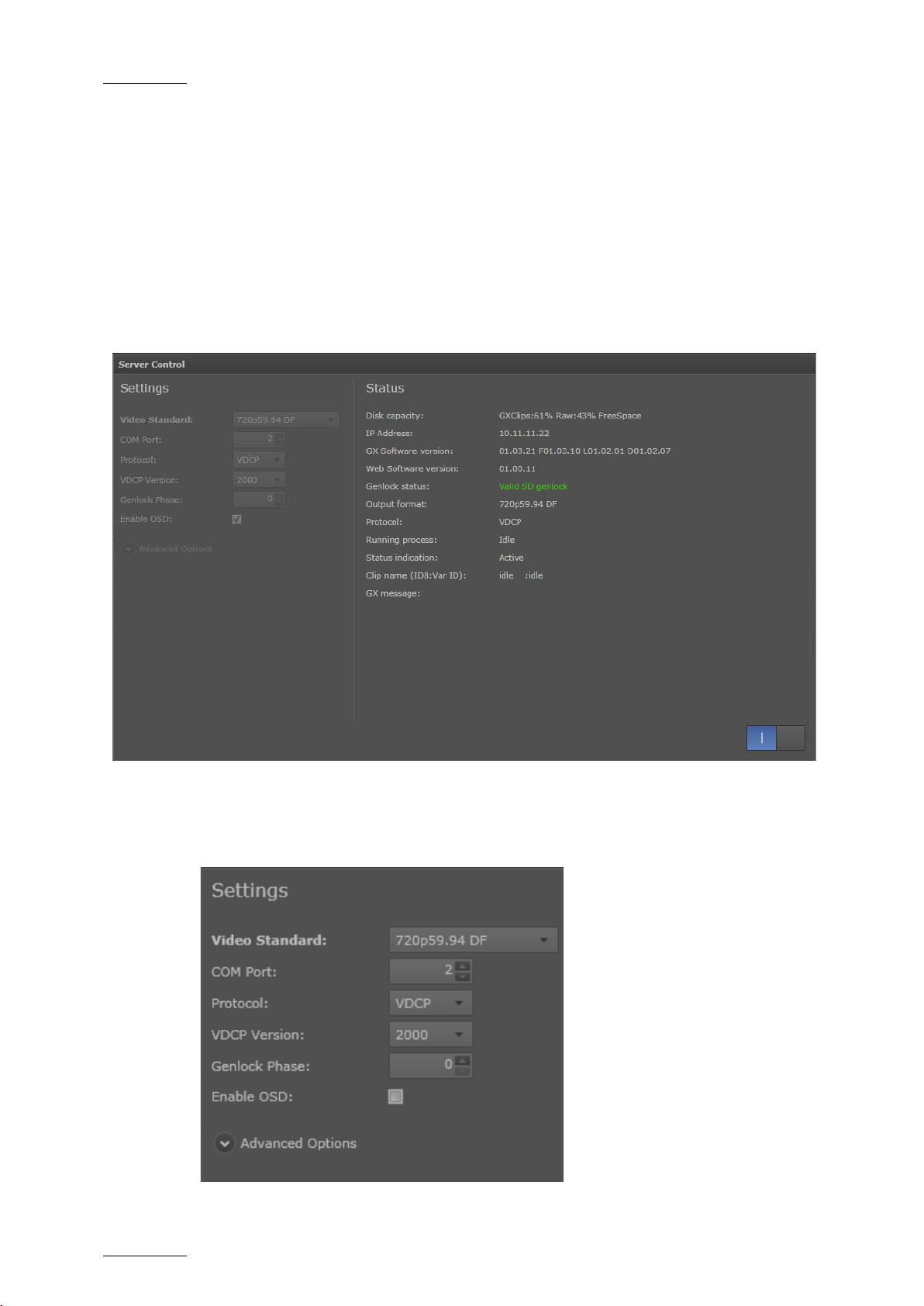
4.2.2 SERVER CONTROL WINDOW
You can configure and start the GX server f rom the Server Control window.
In the top right corner of the main window, the Server Control button gives you
access to the Server Control window where you can d o the f ollowing:
• Start the G X server
• Define the GX server settings
• View GX server status information
EVS Br oadcast Equipment – February 2011
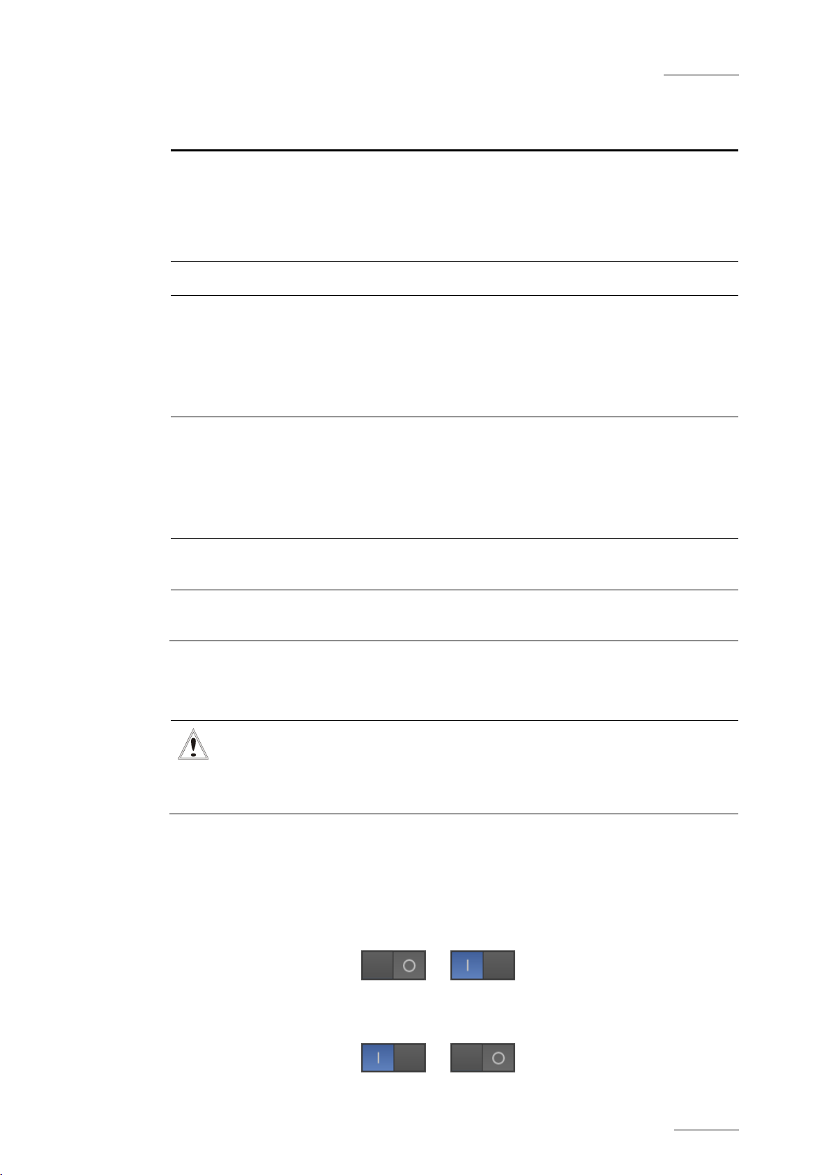
4.2.3 SERVER SETTINGS
Page 23

GX ser ver – Version 1.0 – User’s Manual
EVS Br oadcast Equipment – February 2011
Issue 1.0.C
17
to the protocol
The f ollowing settings for the GX server can be def ined in the S ettings area of the
Server Control window:
Setting Description
Video Standard Video standard the GX server can run in.
The following standards are available:
• SD NTSC DF or SD NTSC NDF
• SD PAL
• 1080i 59.94Hz DF or 1080i 59.94Hz NDF
• 1080i 50Hz
• 720p 59.94Hz DF or 720p 59.94Hz NDF
• 720p 50Hz
Any change in the standard is immediately reflected on the
output and status screen.
When the GX server is started, only GX clips created in the
selected video standard will be visible
clients.
COM Port
Serial port number on the VDCP controller t hrough which the
GX server will communicat e.
Protocol
Protocol the GX server will use to communicate with the
controller.
The VDCP protocol is available on the current GX server
version.
VDCP Version
Version of the VDCP protocol to be used in communications
between the server and the controller.
The versions available are the following: ‘2000’, ‘1998’.
Genlock Phase Phase of t he genlock input on the GX server video board.
Enable OSD
Tick the check box to activate the OSD (status screen) on
the SDI output of the GX server.
Advanced Opt ions
The advance options are hidden by default. They allow users
to specify which information should be included in the logs.
They should only be modified by, or in agreement with the
EVS cust omer support.
Page 24

Issue 1.0.C
GX ser ver – Version 1.0 – User’s Manual
18
4.2.4 SERVER STATUS INFORMATION
The following server st atus information is d isplayed on the right side of the Server
Control window.
EVS Br oadcast Equipment – February 2011
The table below d escribes the s tatus information fields:
Option Description
Disk Capacity
Remaining capacity on both Raw Materials and GX Clips
drives. It is expressed as a percentage of the total drive
capacity.
IP Address
IP address of the network interface card (NIC) that allows
the GX server to communicate over the network.
GX Softw are version Current version of the GX software.
Web Software
Current version of the GX web software
version
Genlock status Type and q uality of genlock.
• The messages on the genlock quality can be the
following:
• Valid:
• Bad (no signal):
Good genlock
No genlock signal detected
• Bad (m ismatch):
Genlock signal det ected, but
not in t he correct form at
If the genlock quality is bad, the genlock information
is displayed in red. Otherw ise, this is in green.
• The type can be ‘tri-level’ or ‘blackburst’.
Page 25
GX ser ver – Version 1.0 – User’s Manual
EVS Br oadcast Equipment – February 2011
Issue 1.0.C
19
are being
The status is ‘Not started’ when the server is not
Option Description
Output format Currently selected video standard.
Protocol Protocol the GX server is currently set to work with
Running process Activity status on the GX server:
Status indication GX server status:
When the GX server is started, only GX clips created in
the selected video standard will be visible to the protocol
clients. The value corresponds to the one selected in the
Vi deo Stan da rd field in the Settings area.
• The status is ‘IMPORTING’ if raw materials are being
imported onto the Raw Materials drive.
• The status is ‘UPLOADING’ if GX clips
uploaded onto the GX Clips drive.
•
running.
• The status is ‘Active’ when the GX server has been
started and is awaiting commands.
Clip name
GX message
Name of the G X clip that has been loaded by the protoc ol
client.
Error, warning or general message reported by the GX
server and displayed on the OSD of the SDI Fill out put.
4.2.5 STARTING THE GX SERVER
Important
Users need to start the GX server manually via the Start Server button
in the web interface when they want GX clips to be made visible to the
protocol clients.
HOW TO START AND STOP THE GX SERVER
The GX server can be started and stopped by clicking the switch icon in the
bottom right corner of the window:
• To start the GX server, click on O.
The icon changes from to
• To stop the GX server, click on I.
The icon changes from to
Page 26
Issue 1.0.C
GX ser ver – Version 1.0 – User’s Manual
20
Import area
Manage area
Access to
Server Control page
PRINCIPLES ABOUT STARTI NG THE SERVER
Once the GX server is switched on, users can connect to and work on the server
via the web interface.
The following principles apply with a GX server:
• The GX server is not automatically started when it is switched on.
• Users need to start the GX server manually via the Start Server button in
the web i nterface when they want to play out the prepared fill and key clips.
• The GX server will only respond to the commands from the control protocol
once the GX server has been started.
• When the GX server is started, it is not possible to import original sequences
and/or create GX clips via the web interface until the server is stopped.
4.3 OVERVIEW ON MAIN WINDOW
EVS Br oadcast Equipment – February 2011
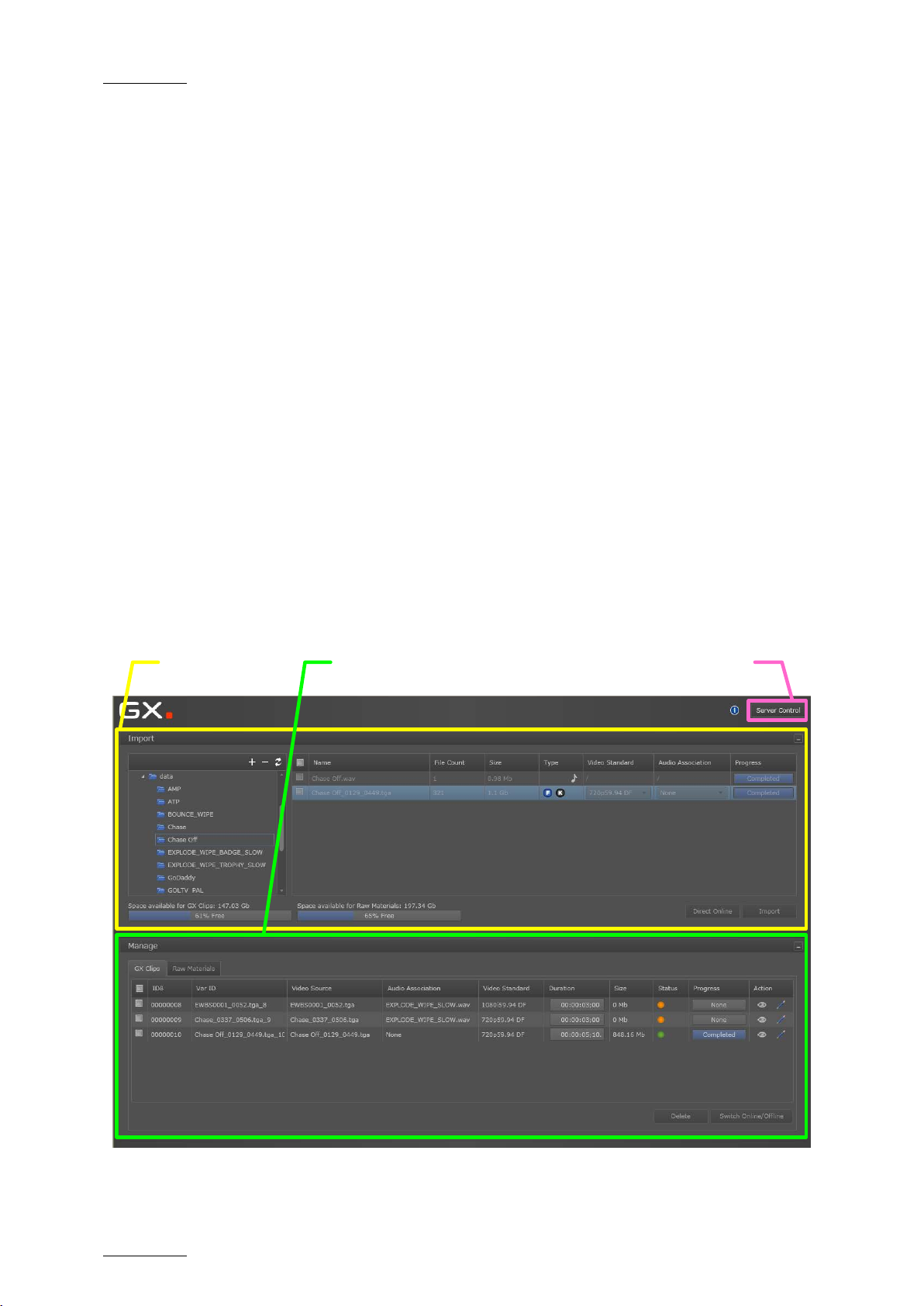
4.3.1 INTRODUCTION
The main window in the user interface contains two main areas shortly described
below:
Page 27

GX ser ver – Version 1.0 – User’s Manual
EVS Br oadcast Equipment – February 2011
Issue 1.0.C
21
1. Drive Tree Structure
2. Source File List
4. Import Buttons
3. Drive Capacity Information
4.3.2 IMPORT AREA
The Import area at the top of the main window allows you to perf orm the following
actions:
• Browsing the drives containing the original sequences and selecting the
sequences to import
• Importing the sequenc es either only to t he Raw Materials drive (HDD drive), or
to the Raw Materials drive and to the GX Clips dr ive (SSD drive)
In this area, you actua lly tag the media and create an entry for it in the GX server
database.
OVERVIEW
The Import ar ea includ es four zones shown in the following schem a and described
in the table below:
# Zone Name Description See al so …
1.
Drive Tree
structure
2. Source File list
3.
Drive Capacity
information
4. Import buttons
Folder structure of the drives availab le on
the GX s erver
List of the source files available in the
selected d rive folder
Information on the space used and
available capacity on the Raw Material and
GX Clips drives
Command buttons for importing the source
files selected in the source file list
Section 5.1
Sections
5.3.1 & 5.3.2
-
Sections
5.3.3 & 5.3.4
Page 28

Issue 1.0.C
GX ser ver – Version 1.0 – User’s Manual
22
2. Raw Material list
4. Command buttons
1. Row selection
3. Action column
4.3.3 MANAGE AREA
The Manage area at the bottom of t he main window allows you to manage:
• the sequences available on the Raw Materials drive f rom the Raw Mat erial tab.
• the G X c lip s from the G X Clips tab.
The GX clips can be offline (only defined in the GX server d atabase) or online
(defined in the database and uploaded ont o t he G X Clips dr ive) .
RAW MATERIAL TAB
The Raw Material tab provides a list of the video sequences and audio files
available on the Raw Materials drive. From there, you can manage the original
files.
EVS Br oadcast Equipment – February 2011
The Raw Material tab includes four zones shown in the following schema and
described in the table below.
# Zone Name Description See also …
1. Row selection
Check box es that allow the selection of
files you want to apply a com mand to.
Section 4.3.5
2.
Raw Material
list
3. Act ion column
4.
Command
buttons
List of all the files (video seq uences and
audio files) available on the Raw Materials
drive.
Command buttons for actions on an
individual file.
Command buttons for actions on the
selected files.
Section 5.3.7
Section 5.3.7
Section 5.3.8
Page 29

GX ser ver – Version 1.0 – User’s Manual
EVS Br oadcast Equipment – February 2011
Issue 1.0.C
23
GX CLIPS TAB
The GX Clips tab provides a list of the GX clips defined in the GX Server database
and also uploaded on the GX Clips drive. From there, you can manage the GX
Clips.
The GX Clips tab includes four zones shown in the following schema and
described in the table below:
# Zone Name Description See al so …
1.
Row
Selection
2. GX Clip s lis t
3. Action column
4.
Command
buttons
Check boxes that allow the selection of files
you want to apply a command to.
Li st of all G X Clips available on the GX Clips
drive, regardless of the server settings
defined.
Buttons to allow the user to edit or preview
the r elated GX clip.
Command buttons for actions on the
selected G X cli ps.
4.3.4 SERVER CONTROL BUTTON
Section 4.3.5
Section 5.4.2
Section 5.5.1
Section 5.4.3
and 5.4.4
In the top right corner of the main window, the Server Control button gives you
access to the Server Control window. You will find detailed information on this
area in the section 4.2.2 'Server Control Window’, on page 16.
.
Page 30

Issue 1.0.C
GX ser ver – Version 1.0 – User’s Manual
24
4.3.5 RULE S FOR ROW SELECTION
The following rules apply for the selection of rows corresponding to source files
(in the Import area), raw materials (in the Raw Materials tab) or GX clips (in the
GX Clips tab):
• To select an individual row, tick the check box in front of the row.
• To select all rows, tick the check box at the upper check box, which d oes not
correspond to any row.
EVS Br oadcast Equipment – February 2011
Page 31

GX ser ver – Version 1.0 – User’s Manual
EVS Br oadcast Equipment – February 2011
Issue 1.0.C
25
5.1 CHAPTER O VERVIEW
This chapter explains how you import the raw material onto the GX server, and
prepare the GX clips for playout. It contains the following sections:
What about … ? Section Page
Drive Tree Structure 5.2.1 Page 27
Drive Display 5.2.2 Page 27
5. Operation
Source File List & Fields in the Source File List
Import Results 5.3.4 Page 30
Display of Imported Elements on the User Interface 5.3.5 Page 32
Raw Mat erials Tab 5.3.6 Page 33
Fields in the Raw Materials Tab 5.3.7 Page 34
GX Clips Tab 5.4.1 Page 37
Fields in the GX Clips Tab 5.4.2 Page 37
Edit GX Clip Window 5.5.1 Page 42
General Principles About TC Fields on the GX Server 5.5.3 Page 47
General Settings in the Edit GX Clips Window 5.5.4 Page 47
Video Settings in the Edit GX Clips Wind ow 5.5.5 Page 49
Audio Settings in the Edit GX Clips Wind ow 5.5.6 Page 51
5.3.1 &
5.3.2
Page 29
Clip Preview in the Edit GX Clip Window 5.5.7 Page 54
Command Buttons in the Edit GX Clip Window 5.5.8 Page 56
GX Clip Duration and Timecodes 5.5.9 Page 57
Page 32

Issue 1.0.C
GX ser ver – Version 1.0 – User’s Manual
EVS Br oadcast Equipment – February 2011
26
How to … ? Section Page
How to Display Folder St ructure and Source Files 5.2.3 Page 27
How to Connect and Disconnect a Network Drive 5.2.4 Page 28
How to Import Files on the GX Server 5.3.3 Page 30
Deleting a File from the Raw Materials Drive 5.3.8 Page 35
Switching GX Clips Online or Offline 5.4.3 Page 39
Deleting GX Clips 5.4.4 Page 41
Editing GX Clips Parameters 5.5.2 Page 44
Page 33

GX ser ver – Version 1.0 – User’s Manual
EVS Br oadcast Equipment – February 2011
Issue 1.0.C
27
5.2 MANAGING DRIVES AND FOLDERS
Before selecting and importing the source files, you need to connect and point to
the drives that contain the source files.
5.2.1 DRIVE TREE STRUCTURE
The dr ives and folders that contain the source files are displayed on the drive tree
structure ( lef t part of t he Import area):
5.2.2 DRIVE DISPLAY
The removable drives connected to the GX server (USB, eSata) and the DVD
drives are automatically displayed in the drive tree structure. The drive letter
assigned and t he drive nam e are displayed.
You need to manually define the local or network drives to display them in the
drive tree st ructure. You also need to disconnec t them manually when you want to
hide them.
The Raw Materials drive, which contains the imported files, is automatically
displayed in t he drive tree structure.
5.2.3 HOW TO DISPLAY FOLDER STRUCTURE AND SOURCE FILES
To view or hide the folder structure below a given driver/folder, click the arrow in
front of this driver/folder:
To view the source files available in a given drive or folder, click the drive or
folder name:
Page 34

Issue 1.0.C
GX ser ver – Version 1.0 – User’s Manual
EVS Br oadcast Equipment – February 2011
28
The supported source files (TGA, TIFF, WAV files) included in the folder selected
will be displayed on the right hand box in the Import area.
5.2.4 HOW TO CO NNECT AND DISCONNECT A NETWORK DRIVE
To m ap a n etwo rk d ri ve ont o t he G X server, proceed as f ollows:
1. Click the + symbol at the top of the drive tree structure.
The Map a shared drive window opens.
2. Type the full path to the folder to be mapped in t he Network Path field, using
the following pattern: \\[ComputerName]\[FolderName].
3. Select a drive letter to be associated to this mapped drive.
4. Type an existing Windows user name t o access the g iven machine in the User
field, us ing one of the following patterns:
o [Domain]\[Username] or username@domain when the target
computer and username are part of a domain.
o [ComputerName]\[Username] or username@compurtername
when username is a local user account on the target computer.
5. Type the Windows pas sword corresponding t o this user name in the Password
field.
6. Click OK.
The network drive is mapped to a drive letter, and is now available in the drive
tree str ucture.
To disconnect the network drive, select it, click the – symbol at the top of the
drive tree structure and confirm the disconnection.
Page 35

GX ser ver – Version 1.0 – User’s Manual
EVS Br oadcast Equipment – February 2011
Issue 1.0.C
29
5.3 SELECTING AND IMPORT ING SOURCE FILES
Once the drives containing the source files are available in the drive tree
structure, you can easily select the requested sources files and import them.
Once imported the source files are stored onto the archive disk, so that they will
still remain available for future use.
5.3.1 SOURCE FILE LIST
The source files available in the folder selected in the drive tree structure are
displayed in the source file list, on the right hand of the Import area:
This list allows you to select the files that you will import using the Direct Online
or the Import button. For more information on importing files, refer to the section
5.3.3 ‘How to Import Files on the GX Server’, on page 30.
When a source file has already been imported onto the GX server, the
corresponding row is dimmed in the Source File list .
5.3.2 FIELDS IN THE SOURCE FILE LIST
The list of sourc e files provid es the following information. The field values are not
editable, unless otherwise is stated in the table.
Field Name Description Values
Name
File Count
Name of the audio file or
the graphic file sequence.
Number of files in the file
sequence.
A graphic file sequence follows the
pattern: [name][first file
number]…[last file
number].[extension]
An audio file follows the usual
pattern: [name].[extension]
The value will be ‘1’ for aud io files.
Size
Type Type of t he file.
Size the file or file
sequence takes up on the
drive.
The value is expressed in Mb or GB.
The values can currently be ‘Audio’
, or ‘Fill & Key’ .
Page 36

Issue 1.0.C
GX ser ver – Version 1.0 – User’s Manual
EVS Br oadcast Equipment – February 2011
30
has already copied during the
‘Completed’ once the import
if there was an error
import option, you can also upload the files
Field Name Description Values
Video
Standard
Audio
Association
Progress
Video standard used in the
graphic file sequence. Not
applicable to audio files.
When a video standard can
have two different field
rates, you can select
another field rate than the
default one.
Select from the list the
audio f ile you want to
associate to t he graphic file
sequence.
Progress bar to show the
progress of the copy to t he
Raw Mat erials drive
The value for video sequences can
be one of these:
• SD PAL
• SD NTSC DF or N DF
• 1080i 50Hz
• 1080i 59.94Hz DF or N DF
• 720p 50Hz
• 720p 59.94Hz DF or NDF
The audio files available in the dropdown field ar e:
• Audio files already copied to the
Raw Mat erials drive
• Audio files selected to be copied
to the Raw Materials drive
The pr ogress bar displays:
• The percentage of the file that
5.3.3 H
OW TO IMPORT FILES ON THE GX SERVER
During the import process, the selected files are imported to the Raw Materials
drive of the GX s erver.
Note
Using the Direct Online
directly to the GX Clips drive with predefined playout settings. In this
case, they would directly be ready for playout.
import process
•
process is finished.
• ‘None’ when the f ile has not been
imported last.
• ‘Error’
during the import. The tooltip
provides information on the given
error.
Page 37

GX ser ver – Version 1.0 – User’s Manual
EVS Br oadcast Equipment – February 2011
Issue 1.0.C
31
To import files onto the GX server, proceed as follows:
1. In the drive tree structure, select the drive and folder that contains the
source files to import.
The source files are displayed in the source file list.
2. Select the files to import in one of t he f ollowing ways:
• To s elec t all displayed files, tick the top check box in the lis t.
• To s elec t individual files, tick t he check box in front of each file you want
to import
3. If you want t o associate an audio file t o a video file, click the d own arrow in
the A udio Association column in the row corr esponding to the video file, and
select the requested audio file.
The audio file you want to associate must have been imported or selected
for import to appear in the list of available audio files.
4. Import the selected files in one of the following ways:
During t he impor t process, a progress bar displays in real time t he progress of the
copy process to the Raw Materials drive.
• Click the Import button to import the file(s) solely to the Raw Materials
drive.
• Click the Direct Online button to import the file(s) to the Raw Materials
drive and to the GX Clips drive (with predefined settings detailed in the
section ‘Import Results’).
Page 38

Issue 1.0.C
GX ser ver – Version 1.0 – User’s Manual
32
of a source file does not succeed, an error message is
displayed in the Progress column. The error message tooltip provides
Note
If the import
informat ion on the error.
5.3.4 IMPORT RESULTS
NORMAL IMPORT
In case of normal import, the files are only imported to the Raw Materials drive,
not to the G X Clips dr ive.
You then need to prepare the GX clip before uploading it to the GX Clips drive.
For more information refer to the section 5.4 ‘Managing GX Clips’, on page 37.
DIRECT ONLINE IMPORT
EVS Br oadcast Equipment – February 2011
In case of a direct online import, the files are directly created as GX files with
predefined settings and uploaded to the GX Clips drive.
The following predefined settings are applied in this import method:
• The first f rame in the video sequence will be used as the IN point.
• The last f rame in the video sequence will be used as the OUT point.
• There will be no audio delays applied t o the sequences.
• There will be no loop va lues : the clip will be s et to play once.
• Where audio associations are required, they must be set on each individual
clip.
5.3.5 DISPLAY OF IMPORTED ELEMENTS ON THE USER INTERFACE
RAW MATERIALS TAB
Both import methods have the following impact on the Raw Materials tab:
• A new row is added on the Raw M aterials tab for each newly imported video or
audio element.
For more d etails, see also the section 5.3.6 ‘Raw Materials Tab’, on page 33.
• The progress bar in a row displays the status ‘Completed’ after the element
has been successfully imported.
This status is reset to ‘None’ for f iles that were not im ported last .
Page 39

GX ser ver – Version 1.0 – User’s Manual
EVS Br oadcast Equipment – February 2011
Issue 1.0.C
33
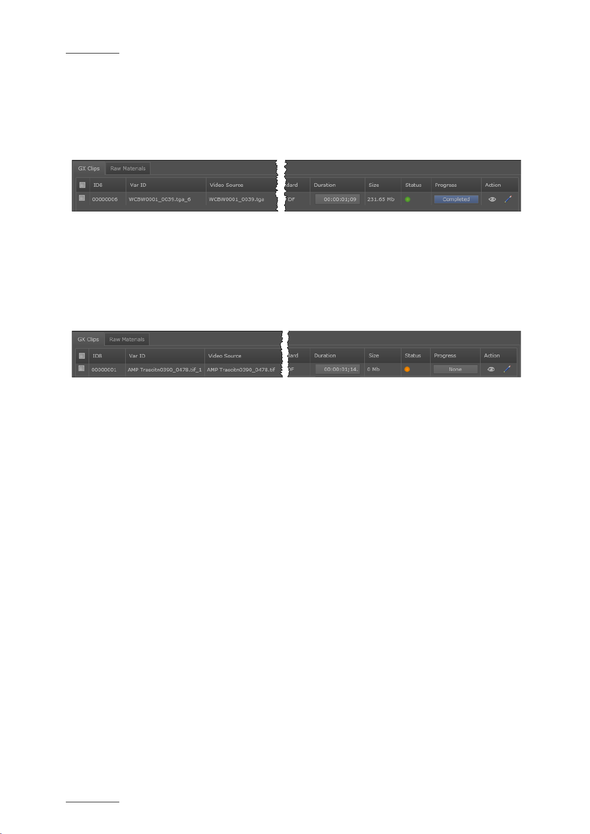
GX CLIPS TAB
For each imported graphic file sequence, whatever the import method, a new row
corresponding to a new GX clip is added on the GX Clips tab.
During the import, the status of the GX clip is grey. This means the clip is being
imported.
After a normal import, the status of the GX clip is orange. This means the clip
has been defined in the GX server database, but has not yet been uploaded onto
the GX Clips drive.
After a Direct Online import, the status of the GX clip is g reen. This means the
clip has been defined in the GX server database, and uploaded onto the GX Clips
dr ive. It is read y for playout.
5.3.6 RAW MATERIALS TAB
The Raw Materials tab shows the audio and video material available on the Raw
material d rive. The Raw Materials drive should be seen as an archive drive where
all the source files are stored and d irectly avai la ble for (re)use.
A new row is added on the Raw Materials tab for each audio or video element
imported to the Raw material drive. If an audio file is associated with several Fill
& Key files, the audio file will be imported once, and will appear once in the Raw
Materials tab.
Page 40

Issue 1.0.C
GX ser ver – Version 1.0 – User’s Manual
34
material was imported to the Raw
has already copied during the
‘Completed’ once the import
tooltip provides information on
5.3.7 FIELDS IN THE RAW MATERIALS TAB
The R aw Materials tab provides t he following information on t he material available
on the Raw Materials drive. T he f ield values are not editable.
Field Name Description Values
EVS Br oadcast Equipment – February 2011
Name
File Count
Type Type of t he file.
Video
Standard
Name of the audio file or the
graphic file sequence.
Number of files in the file
sequence.
Video standard used in the
graphic file sequence. Not
applicable to audio files.
When a video standard can
have two different field
rates, you can select
another field rate than the
default one.
A graphic file sequence follows the
pattern: [name][first file
number]…[last file
number].[extension]
An audio file follows the usual
pattern: [name].[extension]
The value will be ‘1’ for aud io files.
The values can currently be ‘Audio’
, or ‘Fill & Key’ .
The value for video sequences can
be one of these:
• SD PAL
• SD NTSC DF or N DF
• 1080i 50Hz
• 1080i 59.94Hz DF or NDF
• 720p 50Hz
Size
Import
Date
Progress
Size the audio or video file
on the Raw Materials drive.
Date (d efined on the GX
server) where the audio or
video file was imported
Progress bar to show the
progress of the copy to t he
Raw Mat erials drive
• 720p 59.94Hz DF or NDF
The value is expressed in Mb or GB.
The import d ate is the date when the
Materials drive.
The progress bar displays:
• The percentage of the file that
import process
•
process is finished.
• ‘None’ when the f ile has not been
imported last.
• ‘Error’ when there has been an
error in the import process. The
the given error.
Page 41

GX ser ver – Version 1.0 – User’s Manual
EVS Br oadcast Equipment – February 2011
Issue 1.0.C
35
Field Name Description Values
Action
Displays icons corresponding to possible actions on the raw
material:
• : preview the raw material
5.3.8 DELETING A FILE FROM THE RAW MATERIALS DRIVE
Important
PROCEDURE
To delete one or more files from the Raw Materials drive, proceed as follows :
1. Click the Raw Materials tab in the Manage area of the main window.
2. Select the files to delete in one of the following ways:
You should always delete the files stored on the Raw Materials drive
from the GX web interface, never from Windows Explorer.
The files stored on t he Raw Mater ials drive are displayed.
• To s elec t all displayed files, tick the top check box in the lis t.
• To s elec t individual files, tick t he check box in front of each file you want
to delete
3.
Click Delete.
A message similar to the following one is displayed to request precisely
what you want to delete:
Page 42

Issue 1.0.C
GX ser ver – Version 1.0 – User’s Manual
EVS Br oadcast Equipment – February 2011
36
4.
Select what you want to delete in one of the following ways:
• Click Both t o delete both the source file on the Raw Materials drive, the
GX clips ent ry in the d atabase, and the r elated GX clip.
• Click Raw Material to delete only the source file on the Raw Materials
drive. For more information on this action, refer to the ‘Results’ section,
on page 36.
5.
If you want to apply the same Delete action to the other selected files, tick
the check box Apply to X selected i tems.
RESULTS
Deleting Video Raw Material Only
Deleting only the video raw material corresponding to an online GX clip will
however impact the GX clip in the following way:
• If the GX clip is offline, it is automatically deleted.
• If the GX clip is online, it remains available as long as it is online but will be
deleted as soon as it will b e taken offline.
De leti ng A ud io R aw M ate ria l On ly
Deleting only the audio raw material included in one or more GX clips will impact
the GX c lip(s) in the following way:
• If the GX clip is offline, the audio association is automatically removed from
the GX c lip.
• If the GX clip is online, t he audio element will be removed from the GX clip as
soon as the associated GX clip will be taken offline.
Page 43

GX ser ver – Version 1.0 – User’s Manual
EVS Br oadcast Equipment – February 2011
Issue 1.0.C
37
character ID presented
Variable length ID (up to
32 characters) presented
5.4 MANAGING GX CLIPS
5.4.1 GX CLIPS TAB
The GX Clips tab shows the GX clips defined in the GX server database,
information on the GX clips and on their upload status on the GX Clips drive.
For each new graphic file sequence imported to the Raw Materials drive, a new
entry f or a GX clip is created in the GX server dat abase.
As a consequence, a new row is added on the GX Clips tab for this video source,
to allow users to associate an audio file to the video and define playout
parameters for the GX clip.
5.4.2 FIELDS IN THE GX CLIPS TAB
The GX Clips tab provides the following information on the material available on
the GX Clips drive. The field values ar e not ed itable.
You can edit the GX clip parameters in the Edit GX Clips window. For more
informat ion, r efer to the section 5.5.2 ‘Ed iting GX Clips Parameters’, on page 44.
Field Name Description Values
Id8
IdVar
8to a VDCP client when it
obtains a list of GX clips.
to protocol clients that are
able to view long er IDs.
It is generated by incrementing by 1
the Id8 of the last file i mp or t ed t o t h e
Raw Mat erials drive.
It is g enerated based on t he following
pattern: [original file
name][fir st file
number]_[ final file
number].[file
extension]_[ID].
Video
Source
Name of the video raw
material used in the GX
clip
It follows the pattern below:
[name][f irst file
number]…[ final file
number].[extension]
Page 44

Issue 1.0.C
GX ser ver – Version 1.0 – User’s Manual
EVS Br oadcast Equipment – February 2011
38
Field Name Description Values
Audio
Association
Video
Standard
Duration
Name of the associated
audio raw material
Video standard used in the
GX c lip .
Shows the protocol
duration of t he GX clip,
this means t he duration of
the GX clip as it will be
displayed to the protocol
clients.
If no audio file is associated, ‘None’ is
displayed.
If an audio file is associated, the
audio file name is displayed.
The value for video sequences can be
one of t hese:
• SD PAL
• SD NTSC DF or N DF
• 1080i 50Hz
• 1080i 59.94Hz DF or NDF
• 720p 50Hz
• 720p 59.94Hz DF or NDF
The duration is expressed in
HH:MM:SS;ff.
Size
Status
The duration will depend
on the following elem ents:
• IN point
• OUT points
• Number of loops
• Loop d uration
Size the G X clip on the G X
Clips drive.
Gives the status of the GX
clip on the server.
The value is expressed in Mb or GB.
When the GX clip is not upload ed onto
the GX Clips drive, the value is 0 Mb.
Four st at uses are possible:
: T he G X cli ps are queued to be put
online in a Direct Online process.
: The GX clip is offline. This means
it is defined in the GX server
databas e, but not yet uploaded on the
GX Clips d rive.
: The GX clip is online. This means
it is defined in the GX server database
and uploaded on the GX Clips d rive.
: T he original files used in the GX
clip are being imported to the Raw
Material drive.
Page 45

GX ser ver – Version 1.0 – User’s Manual
EVS Br oadcast Equipment – February 2011
Issue 1.0.C
39
already copied during the upload
‘Completed’ once the upload is
: preview the GX clip taking into account all defined
settings. The elements in the preview are equivalent to the
Field Name Description Values
Progress
Progress bar to show the
progress of the upload to
the GX Clips drive
The progress bar displays:
• Which percentage of the file has
process
•
finished.
• ‘None’ when the file has not been
uploaded last.
Action Displays icons corresponding to possible actions on the G X clips :
•
preview in the Edit GX Clip window.
• : opens the Edit GX Clip window to edit the GX clip
5.4.3 SWITCHING GX CLIPS ONLINE OR OFFLINE
PRINCIPLES
Offline GX clips are defined in the GX server database but not yet uploaded on
the GX Clips drive. When GX clips are offline, they are fully editable and can be
edited in the Edit GX Clips window (S ee also sect ion 5.5).
When the clips are ready for playout, you need to upload them to the GX Clips
drive: this is the process of putting the GX clips online. Only the GX clips
imported using the Direct Import option are automatically put online.
Important
Online GX clips only will be visible to the protocol clients when the GX
server will be started.
PROCEDURE
To put a GX clip online or t o ta ke it offline, proceed as f ollows:
1. In the GX Clips tab, select the GX clips to be put online/ offline
2. Press the Switch online/offline button.
During an upload, the progress bar shows how much of the GX Clip has been
copied t o the GX Clips drive.
Note
Switching offline a GX clip whose corresponding raw material has been
deleted will automatically delete the GX clip.
Page 46
Issue 1.0.C
GX ser ver – Version 1.0 – User’s Manual
EVS Br oadcast Equipment – February 2011
40
CONSEQUENCES
When a GX clip is put online, the row corresponding to this GX clip on the GX
Clips tab will appear as follows:
• After the upload, the Progress bar displays the ‘Completed’ status.
• The size of the GX clip on t he GX Clips drive will be d isplayed.
• The stat us of the GX clip c hanges from orange t o green.
When a GX c lip is offline or is tak en offlin e, the row correspond ing to this GX c lip
on the GX Clips tab will appear as follows:
• After the upload, the Progress bar displays the ‘None’ status.
• The size of the GX clip on t he GX Clips drive is back t o 0Mb.
• The status of the GX clip changes from green to orange.
Page 47

GX ser ver – Version 1.0 – User’s Manual
EVS Br oadcast Equipment – February 2011
Issue 1.0.C
41
5.4.4 DELETING GX CLIPS
Important
You should always delete the files stored on the GX Clips tab from the
GX web interface, never from Windows Explorer.
Deleting GX clips from Windows Explorer will result in stranded records
in the d atabase, and problems with GX server operation.
DEFINITION
Deleting a GX clip means:
• Deleting the GX clip from the GX Clips drive, as well as its reference from the
database
AND
• Deleting the corresponding raw material from the Raw material drive (if it still
exists).
PROCEDURE
To delete one or more GX clips from the GX Clips drive, its reference from the
database and the corresponding raw material from the Raw Materials drive,
proceed as follows:
1. Click the GX Clips tab in the Manage area of the main window.
All GX clips defined in the G X server d atabase are d isplayed in the tab.
2. Select the GX Clips to delete in one of t he following ways:
• To s elec t all displayed GX clips, click the top check box in the lis t.
• To s elec t individual GX clips, c lick the check box in front of each f ile you
want to d elete
3. Click Delete.
RESULTS
Whatever the GX clip status (online or offline), the GX clip will be removed from
the GX Clip drive and from the Raw Material drive. Its reference will be removed
from t he database.
If the GX clip contains an aud io element, the audio raw material is only deleted if
it is not associated with another GX clip.
Page 48

Issue 1.0.C
GX ser ver – Version 1.0 – User’s Manual
EVS Br oadcast Equipment – February 2011
42
5.5 PREPARING GX CLIPS FOR PL AYOUT
5.5.1 EDIT GX CLIP WINDOW
INTRODUCTIO N TO THE EDIT GX CLIP WINDOW
In the Edit GX Clip window, you can perform the following actions:
• Preview the fill, key or fill & key tracks of a GX c lip
• Monitor t he audio track of a G X c lip
• Specify the various settings for playing out the GX clip
Note
You can only edit the GX clip playout settings as long as the GX clip is
offline (not uploaded yet on the GX Clip d rive).
The preview and audio monitoring remain available whatever the clip
status.
ACCESSIN G T HE EDIT GX CLIP WINDOW
You access the Edit GX Clip window by clicking the pen icon , which is
highlighted in yellow in the screenshot below. The pen icon is located on the GX
Clips tab of t he M anag e area of the GX web interface.
Page 49

GX ser ver – Version 1.0 – User’s Manual
EVS Br oadcast Equipment – February 2011
Issue 1.0.C
43
1. General fields
6. Command
buttons
3. Video
settings
2. Audio
settings
4. Video display
5. Preview
progress bar
OVERVIEW OF THE EDIT GX CLIP WINDOW
# Zone Name Description See also …
1. G eneral field s General infor mation on the GX clip Section 5.5.4
2. V id eo se tti ngs Video settings for the GX clip playout Section 5.5.5
3. A ud io se tti ngs Audio settings for the GX clip playout Section 5.5.6
4. V ideo preview
5.
Preview
progress bars
Display and commands to preview the video
fi ll, key o r fi ll & ke y tracks of the G X clip
Bar to show the progress of the video or
audio preview being played
Section 5.5.7
& 5.5.8
-
Page 50

Issue 1.0.C
GX ser ver – Version 1.0 – User’s Manual
EVS Br oadcast Equipment – February 2011
44
You can edit GX clip parameters as long as the status of the
# Zone Name Description See also …
6.
Command
buttons
Command buttons to validate or cancel the
video or audio settings, or even save them
as a profile
5.5.2 EDITING GX CLIPS PARAMETERS
WHERE?
The GX clips’ parameters can be modified from the Edit GX Clip window. You can
access t his window by clicking the pen icon in the row that c orresponds t o the
clip you want to edit in the G X Clips t ab.
Important
corresponding G X clip is offline (the clip on ly exists in t he database, but
has not yet been uploaded on the GX Clip drive).
Section 5.5.8
The values you have edited in the Edit GX Clip window are only
validated as you press OK to leave the wind ow.
HOW TO EDIT A TIMECODE FIELD?
You need t o take the following rules into acc ount when you edit a timecode field.
How to Edit the Whole Timecode Field
To enter a value f or the whole timecode, proceed as follows:
1. Click once the requested timecode field.
The whole timecode is selected.
2. Type all digits of the requested timecode value, without separators, from the
hours t o the frames.
3. Press ENTER to validate the change, or ESC to cancel it.
The defined timecode is displayed with t he separators:
If the timecode you have typed is not valid, the original valu e is kept.
Page 51
GX ser ver – Version 1.0 – User’s Manual
EVS Br oadcast Equipment – February 2011
Issue 1.0.C
45
field in the
During playout, when the clip reaches its OUT
back to the IN point as many
How to Edit Two Digits of a Timecode Field
To enter a value f or only t wo digits of a tim ecode field, proceed as follows:
1. Double-click the two digits in the timecode field you want to modify.
Only the selected digits in the timec ode are highlighted.
2. Type the digit from left to right.
If you type more than two d igits, you will jump to t he next two digits on the
right.
3. Press ENTER to validate the change, or ESC t o canc el it .
The updated timecode is dis played.
If the timecode you have typed is not valid, the original valu e is kept.
POSSIBLE EDITING ACTIONS?
In order to … Do the following …
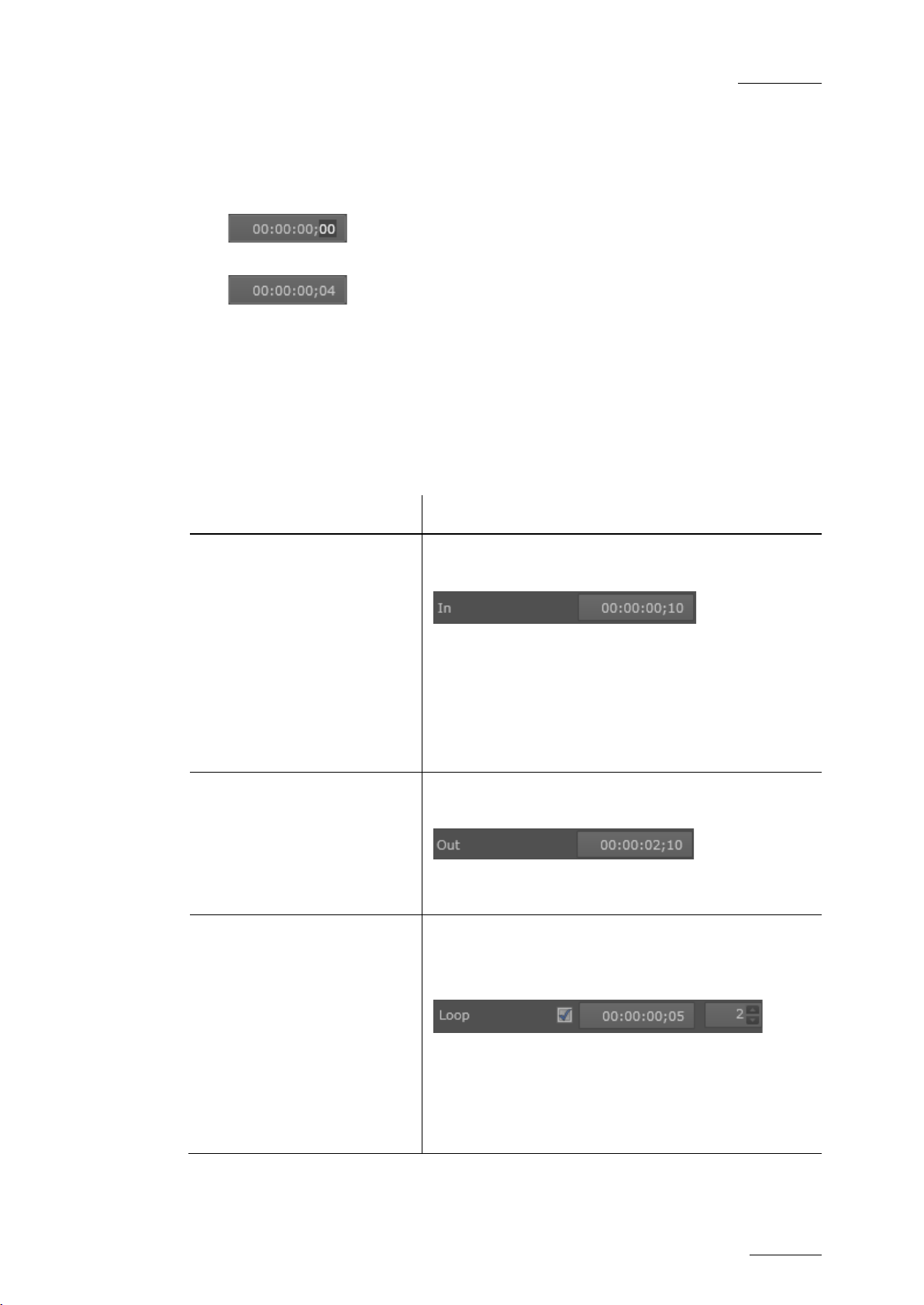
Modify the IN point of a G X
clip (for both video and
audio trac ks)
Enter the requested TC in the IN
General section, and press ENTER.
By default, the IN point of t he GX clip is the first
frame of the imported video sequence, and
corresponds t o the timecode 00: 00:00:00.
The IN point can never be after the OUT point or
the loop point.
Modify the OUT point of the
video or audio in the GX clip
Define a loop on the whole
GX c lip (fr om TC IN to video
TC OUT)
See also the section ‘In Field’, on page 48.
Enter the requested TC in the OUT field of the
Video or Audio section, and press ENTER.
See also the section ‘(Video) Out Field’, on page
49 and ‘(Audio) OUT Field’, on pag e 51.
Tick the check box after the Loop field and type
the number of loops for the GX clip.
The loop point corresponds to the TC IN by def ault .
point, it will loop
times you have defined.
See also the section ‘(V ideo) Loop Fields’, on pag e
50.
Page 52

Issue 1.0.C
GX ser ver – Version 1.0 – User’s Manual
EVS Br oadcast Equipment – February 2011
46
In o rd er to … Do the following …
Define a loop on a portion of
the video track of the GX
clip
Associat e an audio track to
th e vid eo t rac k of the G X
clip
Tick the check box after the Loop field, t ype the
timecode of the loop point and type t he number of
loops for the GX clip.
During playout, when the clip reaches its OUT
point, it will lo op back to the loop point as many
times you have defined.
The loop point has to be defined between the IN
and OUT points.
See also the section ‘(Video) Loop Fields’, on page
50.
Click the d rop-down list box and select an audio
track from the list. The list displays a ll aud io tracks
saved on t he Raw Materials drive.
Define a d elay ( in msec.) in
the audio playout
Define a background color
for G X cli p preview
In the Delay box, type or select the number of
milliseconds’ delay you want to apply to the audio
track. The delay can be positive or neg ative.
See also the section ‘(Audio) Delay Field’, on page
52.
Move the mouse pointer to the video display and
click the icon in the upper rig ht corner t o display
the RGB s cales:
Then m ove the sliders for the red (R), green (G)
and blue (B) scales to define the requested
background color:
The color on the video display is automatically
adapted to the RGB settings defined.
Page 53
GX ser ver – Version 1.0 – User’s Manual
EVS Br oadcast Equipment – February 2011
Issue 1.0.C
47
5.5.3 GENERAL PRINCIPLES ABOUT TC FIELDS ON THE GX SERVER
The following general principles are applicable to the various IN, OUT, TC fields
and other fields displayed in the Edit GX Clip window and the GX Clips t ab:
• The IN and OUT points, and other TC-related fields defined as general, video
and audio settings for the GX clip refer to the timecodes defined on the raw
materials. In other words, the reference timecode is always TC 00:00:00:00 of
the raw material.
• The start timecode of the GX clip as it is played out and displayed to the
external controllers is always 00:00:00:00.
• All frames of a GX clip are played out. In other words, a GX clip that lasts 2
seconds will be played f rom TC 00:00:00:00 to TC 00: 00: 01:24 (for 50Hz clips)
or TC 00:00:01:29 (for drop-frame 60Hz clips) if the corresponding raw
material is played out from start to end.
• The GX clip length corresponds to the length of the longest raw material
(either audio or video), including possible loops.
5.5.4 G
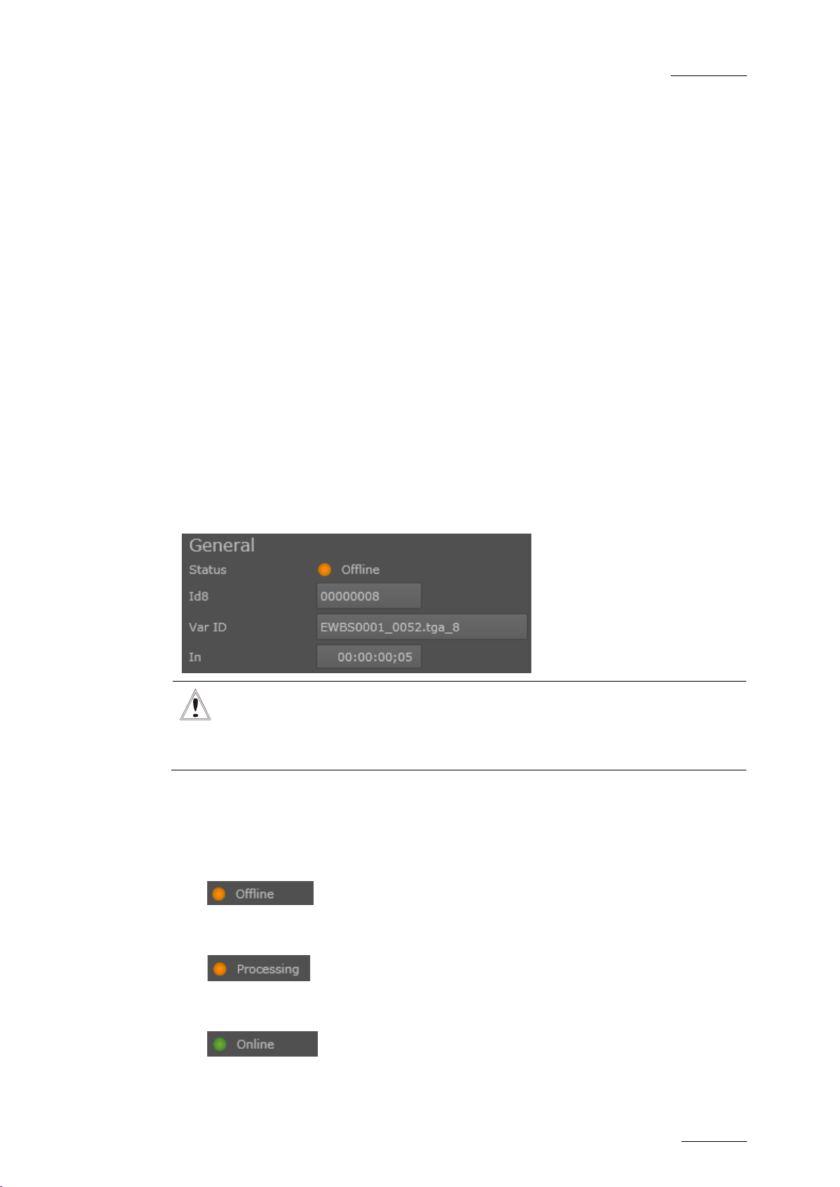
STATUS FIELD
The Status field gives the status of the GX clip on the server. The possible
statuses in the Edit GX Clip window are:
•
ENERAL SETTINGS IN THE EDIT GX CLIPS WINDOW
Important
When you modify a field value in the
need to press ENTER t o validat e the change.
The GX clip is defined in the database, but is not uploaded on the GX Clips
drive.
Edit GX Clip window, you always
•
•
The GX c lip is d efined in the database, and is being uploaded on the GX Clips
drive to be ready for play back.
The GX clip is defined in the d atabase, and upload ed on t he GX Clips drive.
Page 54

Issue 1.0.C
GX ser ver – Version 1.0 – User’s Manual
EVS Br oadcast Equipment – February 2011
48
ID8 FIELD
The Id8 field provides the 8-character ID presented to a VDCP client when it
obtains a list of GX clips.
It is generated by incrementing by 1 the Id8 of the last file imported to the Raw
Materials drive.
IDVAR
The IdVar field provides the variable length ID (up to 32 characters) presented to protocol clients t hat are able to view longer IDs.
It is generated based on the following pattern: [original file
name][first file number]_[final file number].[file
extension]_[ID].
IN FIELD
The IN field gives the timecode, on the raw m aterials, at which t he GX clip should
start. This is applied to both the video and audio tracks.
The reference timecode (00:00:00:00) corresponds to the beginning of the
corresponding video and audio raw materials.
Example
If the IN field value is 00:00:00:10, this means both video and audio tracks of the
GX clip will start playing 10 frames after the start of the raw material.
Page 55

GX ser ver – Version 1.0 – User’s Manual
EVS Br oadcast Equipment – February 2011
Issue 1.0.C
49
GX Clip Video OUT
00:00:01:09
Video Raw Material
00:00:00:00
00:00:00:05
00:00:00:10
00:00:00:15
00:00:00:20
00:00:01:00 00:00:02:00 00:00:03:00
GX Clip IN
00:00:00:00
GX Clip OUT
00:00:02:14
Audio Raw Material
GX Clip
GX Clip Playout
00:00:01:20
OUT FIELD
(Video)
5.5.5 VIDEO SETTINGS IN TH E EDIT GX CLIPS WINDOW
Note about the examples
The frame rate used in the examples below is 50i (25 f/ sec).
The schemas in the examples show the field values as defined on the
raw materials, and the corresponding TC values of the GX clip that will
be displayed to external controllers.
(VIDEO) OUT FIELD
The video OUT field gives the timecode, on the video raw material, at which the
GX clip should end.
The reference timecode (00:00:00:00) corresponds to the beginning of the video
raw material.
Example
In this example, the video raw material used for the GX clip is 2 seconds. The IN
field is 00:00:00:10. The video OUT point defined for the GX clip is on TC
00:00:01:20 of the corresponding raw material.
This means the video track of the GX clip will be played out from TC 00:00:00:10
up to TC 00:00:01:20 of the video raw material.
Page 56

Issue 1.0.C
GX ser ver – Version 1.0 – User’s Manual
EVS Br oadcast Equipment – February 2011
50
(VIDEO) RAW DURATION FIELD
The video Raw Duration field gives the total duration of the video raw material
used in t he GX clip. This field is not ed itable.
This d uration does not take into account t he following elements:
• the start timecode for the GX clip, d efi ned in the IN field
• the end timecode for the video track of the GX clip, defined with the Video
OUT point
• the loops defined (number of loops and loop length).
(VIDEO) LOOP FIELDS
Loop Check Box
The Loop check box needs to be ticked when the video track or part of it should
be played out in loop.
When you t ick the check box, t wo additional f ields are displayed:
• The timecode at which the loop starts ( Loop Point).
• The num ber of times the loop is performed (Loop Recurrence).
Loop Point Field
The Loop Point field allows users to specify the timecode in the video raw
material at which the loop will start. The loop will always be performed from that
point to the Video OUT field.
The GX server will perform a nested loop if the loop point is set to anything other
than the IN frame.
Loop Recurrence Field
The Loop Recurrence field allows users t o specify how many times the loop of the
will be performed during playout.
When a loop recurrence is defined, the total duration of the GX clip specified
below the video display is automatically adapted.
Note
You will find an example on loops in the section 5.5.9 ‘GX Clip Duration
and Tim ecodes’, on pag e 57.
Page 57

GX ser ver – Version 1.0 – User’s Manual
EVS Br oadcast Equipment – February 2011
Issue 1.0.C
51
5.5.6 AUDIO SETTINGS IN TH E EDIT GX CLIPS WINDOW
Note about the examples
The frame rate used in the examples below is 50i (25 f/ sec).
The schemas in the examples show the field values as defined on the
raw materials, and the corresponding TC values of the GX clip that will
be displayed to external controllers.
(AUDIO) ASSOCIATION FIELD
The audio Association field allows you to select the audio file to associate to the
video raw m aterial.
The audio files available in the drop-d own field are:
• Audio files already copied to the Raw Materials drive
• Audio files selected to be copied to t he Raw Materials drive
(A
UDIO) OUT FIELD
The audio OUT field gives the timecode, on the audio raw material, at which the
GX clip should end.
The reference timecode (00:00:00:00) corresponds to the beginning of the audio
raw material.
Example
In this example, the audio raw material used for the GX clip is 3 seconds. The IN
field is 00:00:00:10. The audio OUT point defined for the GX clip is on TC
00:00:02:10 of the corresponding raw material.
This means the audio track of the GX clip will be played out from TC 00:00:00:10
up to TC 00:00:02:09 of the audio r aw material.
In the example, the audio track defines the length of the GX clip since it is the
longest trac k.
Page 58
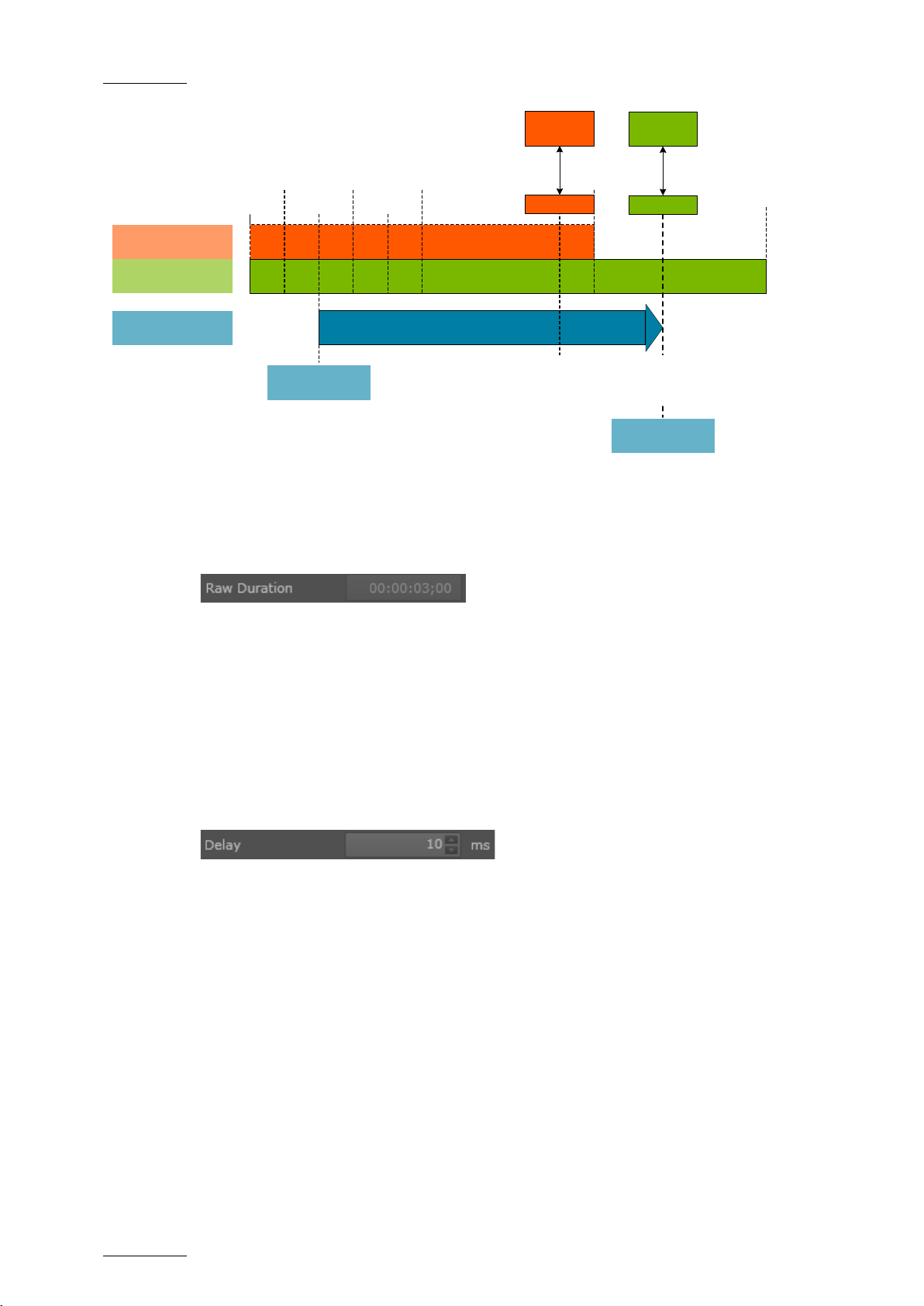
Issue 1.0.C
GX ser ver – Version 1.0 – User’s Manual
EVS Br oadcast Equipment – February 2011
52
Video Raw Material
00:00:00:00
00:00:00:05
00:00:00:10
00:00:00:15
00:00:00:20
00:00:01:00 00:00:02:00 00:00:03:00
GX Clip IN
00:00:00:00
GX Clip OUT
00:00:01:24
Audio Raw Material
GX Clip GX Clip Playout
00:00:01:20
OUT FIELD
(Video)
00:00:02:10
OUT FIELD
(Audio)
GX Clip
Audio OUT
00:00:01:24
GX Clip
Video OUT
00:00:01:09
(AUDIO) RAW DURATION FIELD
The audio Raw Duration field gives the total duration of the audio raw material
used in t he GX clip. This field is not ed itable.
This d uration field does not take into account t he following elements:
• the start timecode for the GX clip, defined in the IN field
• the end timecode for the audio track of the GX clip, defined with the audio
OUT point
(AUDIO) DELAY FIELD
The audio Delay field gives the delay in the playout, in ms, applied to the audio
track. The delay can be positive or negative. Examples are provided for positive
and negative delays.
Posi tive De lay
If the delay is positive (this means the audio track starts after the video track),
silence matching the delay duration will be inserted before the start of the audio
track.
Example
In the following example, a positive delay of 10 milliseconds has been defined.
Silence will be added from the GX Clip IN point for the length of the delay. The
audio track will then be played normally until the audio tr ack OUT point.
Page 59

GX ser ver – Version 1.0 – User’s Manual
EVS Br oadcast Equipment – February 2011
Issue 1.0.C
53
Video Raw Material
00:00:01:00
GX Clip IN
00:00:00:00
GX Clip OUT
00:00:01:24
Audio Raw Material
GX Clip
Video Track
00:00:02:00
Audio Track
SILENCE
00:00:00:00
Possible IN and OUT points defined on the audio track are taken into
Video Raw Material
GX Clip IN
00:00:00:00
GX Clip OUT
00:00:01:24
Audio Raw Material
GX Clip
Video Track
00:00:02:00
Audio Track
AUDIO TRIMMED
00:00:01:00
00:00:00:00
Note
account.
Negative Delay
If the delay is negative (this means the audio track starts before the video track),
the start of the audio will be t rimmed.
Example
In the following example, a negative delay of 10 milliseconds has been d efined. In
other words, the first 10 milliseconds of the audio track are trimmed and the rest
of the audio track will then be played normally from the IN point until the audio
track OUT point.
Page 60

Issue 1.0.C
GX ser ver – Version 1.0 – User’s Manual
54
5.5.7 CLIP PREVIEW IN THE EDIT GX CLIP WINDOW
VIDEO DISPLAY
The video display makes it possible to preview the fill element, key element or
combined fill & key elements, depending on the radio button you select below the
video display.
The pr eview will fill the preview screen for 16x 9 clips.
The preview of 4:3 clips will display black stripes on the left and right of the video.
EVS Br oadcast Equipment – February 2011
PREVIEW CONTROL COMMANDS
The following fields and play commands are availa ble belo w the video display:
# Field/Button Description
1. Progress/Scrub bar
The bar below the video display serves two
purposes:
• The bar (progress bar) is gradually filled with a
blue background that shows how much of the clip
has been loaded ready for playback:
Page 61

GX ser ver – Version 1.0 – User’s Manual
EVS Br oadcast Equipment – February 2011
Issue 1.0.C
55
. Dragging the
bullet, you can also scrub along the clip to
# Field/Button Description
• As you preview the G X clip, the marker s hows the
current position in the GX clip
preview it.
2. Current TC
3. Total Duration
4.
Go to IN
Shows the timecode of the current position in the GX
clip preview.
The GX c lip always starts at 00:00:00:00.
Shows the protocol duration of the GX clip, this
means the duration of the GX clip as it will be
displayed to the protocol clients.
The duration will depend on the following elements:
• IN point
• OU T points
• Number of loops
• Loop d uration
For more information, refer to the section 5.5.9 ‘GX
Clip Duration and Timecodes’, on page 57.
Recues to the IN point of the GX clip.
If the IN point is higher than 00:00:00:00, it is not
possible to preview before then IN point unless the
user changes the IN point.
5.
Previous F rame
6.
Play/Pause
7.
Next Frame
8.
Go to OUT
9.
Video Track
Selection
Goes to the previous frame relative to the current
position.
Plays from or pauses at the current position. This is
a Play/Pause toggle button.
If you press this button at the end of the clip, the clip
will recue.
Goes to t he next frame relative to the curr ent
position.
Goes to t he OUT point of the GX clip.
Radio buttons that allow selecting which video
element you want to preview (fill, key or fill & key):
Page 62
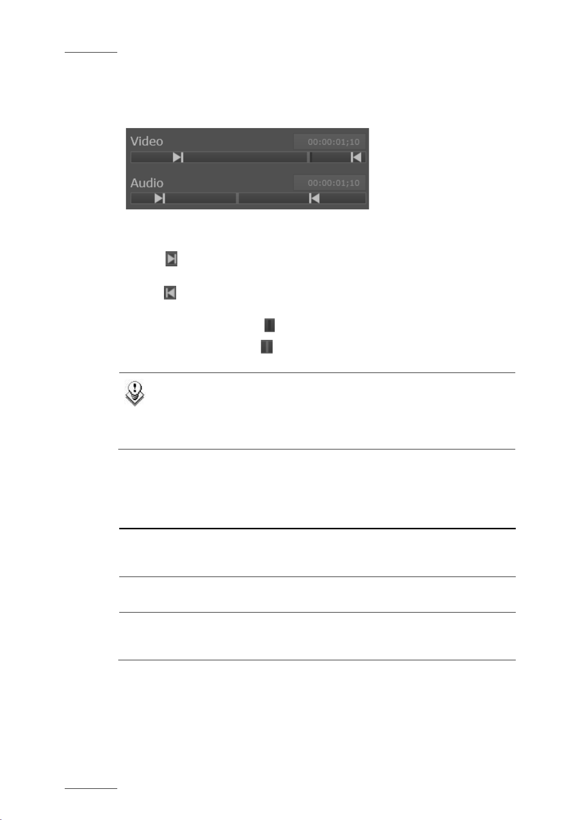
Issue 1.0.C
GX ser ver – Version 1.0 – User’s Manual
EVS Br oadcast Equipment – February 2011
56
will move between the IN and OUT
VIDEO AND AUDIO BARS
The video and audio bars represent the playbac k position in the corresponding raw
material.
The bars and the displayed elements have the following meaning:
• The bar s represent the raw material.
• The sign represents the IN point. It will be positioned relative to the IN
field value in the raw material.
• The sig n represents the OUT point. It will be positioned r elat ed to the OUT
field values (separate fields for audio and video) in the raw m aterial.
• The black vertical marker represents the loop point.
• The gr ey vertical marker represents the current posit ion in t he raw material
during playback.
Note
If the GX clip contains a nested loop (the loop point does not start on the
TC IN point), the playback marker
points for the first pass. Then, for each nested loop, the marker will just
move through the area between the loop point and the O UT point .
5.5.8 COMMAND BUTTONS IN THE EDIT GX CLIP WINDOW
Button Description
Create New
OK
Cancel
Allows users to s ave the clip currently being edited as
a new clip, when a new Id Var and Id8 have been
defined.
Saves and validat es the g eneral, video and audio
settings def ined.
Discards all modifications performed on general, video
and audio settings, and returns back to the settings
defined when the user opened the window.
Page 63
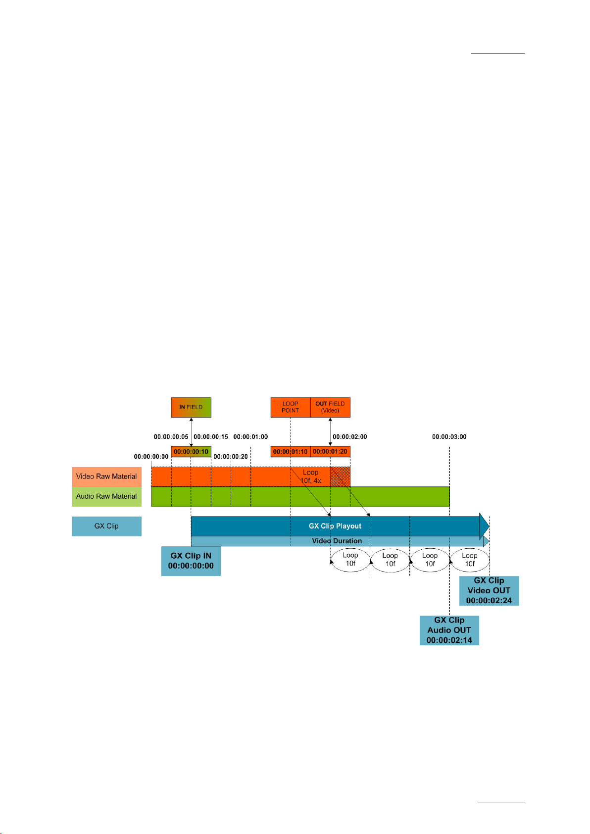
GX ser ver – Version 1.0 – User’s Manual
EVS Br oadcast Equipment – February 2011
Issue 1.0.C
57
5.5.9 GX CLIP DURATION AND TIMECODES
PURPOSE
Based on an example, this section explains how:
• The protocol duration is calculated
• The timecodes of the GX clip are displayed, compared to the timecode of the
raw materials.
EXAMPLE
In the example, the follow ing settings have been defined:
• The video raw material is 2 s eco nds. T he audio raw material is 3 seconds
• The GX clip starts at TC 00:00:00:10 of the video and audio raw material (IN
field = 00:00:00:10).
• The GX clip stops at TC 00:00:01:20 of the corresponding video raw material
(OUT field = 00:00:01:20).
• A loop is defined on the video track from the loop point 00:00:01:10 to the
video OUT point of the GX clip. The loop should be played 4 times.
Page 64

Issue 1.0.C
GX ser ver – Version 1.0 – User’s Manual
EVS Br oadcast Equipment – February 2011
58
Last Frame of Video and Audio Tracks
The last frame of the video track c an be calculated as follows:
00:00:01:20 + 00:00:00:10*4 (4 loops) – 1f = 00:00:03:04.
As an IN f ield is defined at 00:00:00:10, t he last frame of t he video track of the GX
Clip is 00:00:03:04 – 00:00:00: 10 = 00:00:02:24.
The last frame of the audio t rack of the GX clip is 00:00:03:00 – 00:00:00:10 -1f =
00:00:02:14.
Durat ion of the Video and Audio Tracks
The dur ation of the vi d eo t ra ck in the G X clip can be c alculated as follows:
(OUT-IN+1)+#loops*(OUT-Loop+1) =
(00:00:01:20-00:00:00:10+1)+4*(00:00:01:20-00:00:01:10+1) =
00:00:01:11+(00:00:00:11)*4 = 00:00:01:11+00:00:01:19
00:00:03:05
Duration of the GX Clip
The GX c lip lengt h always has t he lengt h of the longest track:
• Without the 4 video loops, the GX clip would last 3 seconds since the audio
track would be longer than the video track.
• As 4 video loops have been defined, the video track is longer than the audio
track.
In this case, the duration of the video track, that is 00:00:03:05, is the longest
one, henc e gives the length of the GX clip.
Page 65

GX ser ver – Version 1.0 – User’s Manual
EVS Br oadcast Equipment – February 2011
Issue 1.0.C
59
Timecode used with NTCS formats having a frame rate of
fps. As timecode can only be represented by whole
Term Definition
24 bit f ile F ile that contains either the key or the fill i mag es .
32 bit f ile F ile that contains both the key and the f ill images.
DF (drop-frame)
Fill clip Clip containing the color portion of the video material
Glossary
29.97
numbers, timecode numbers are periodically skipped in dropframe timecode (no video frames dropped) so that a video
frame is always associated with a timecode.
GX Clips drive
GX c lip
Solid State Drive (SSD), on the GX server, on which the GX
clips are stored and played out.
Fill and key clips (with or without embedded audio), that has
been uploaded to the GX Clips dr ive, and is ready for playout.
• An offline GX clip is a GX clip only defined in the GX server
database.
• An online GX clip is a GX clip defined in the GX server
databas e and uploaded on the GX Clips drive.
Import
Ke y cli p Clip containing the matter used to display transparency.
NDF ( non drop-
frame)
Raw material
drive
Removable
drive
Process of copying t he material from t he removable drive to the
Raw Mat erials drive.
Timecode where every frame of the video has a corresponding
timecode number.
HDD drive, on the GX server, on which the original footage is
stored.
Drive from which the media is being imported, connected
directly to the GX server via a USB or eSATA connector.
Sequence Files before t hey are uploaded t o the GX Clips drive
Upload
Process of copying t he material from t he Raw Materials drive to
the GX Clips drive.
Page 66

EVS Broadcast Equipment
Liège Science Park
16, rue Bois St Jean
B-4102 Ougrée
Belgium
Corporate
Headquarters
+32 4 361 7000
To learn more about EVS go to www.evs.tv
North & Latin America
Headquarters
+1 973 575 7811
Asia & Pacific
Headquarters
+852 2914 2501
Other regional offices
available on
www.evs.tv/contact
 Loading...