


10cc
GAS/PETROL
Evolution® Gas Engines

EN
NOTICE
All instructions, warranties and other collateral documents are subject to change at the sole discretion of Horizon Hobby, Inc. For up-to-date product literature, visit horizonhobby.com and click on the support tab for this product.
Meaning of Special Language
The following terms are used throughout the product literature to indicate various levels of potential harm when operating this product:
NOTICE: Procedures, which if not properly followed, create a possibility of physical property damage AND a little or no possibility of injury.
CAUTION: Procedures, which if not properly followed, create the probability of physical property damage AND a possibility of serious injury.
WARNING: Procedures, which if not properly followed, create the probability of property damage, collateral damage, serious injury or death OR create a high probability of superficial injury.
WARNING: Read the ENTIRE instruction manual to become familiar with the features of the product before operating. Failure to operate the product correctly can result in damage to the product, personal property and cause serious injury.
This is a sophisticated hobby product and NOT a toy. It must be operated with caution and common sense and requires some basic mechanical ability. Failure to operate this Product in a safe and responsible manner could result in injury or damage to the product or other property. This product is not intended for use by children without direct adult supervision. Do not attempt disassembly, use with incompatible components or augment product in any way without the approval of Horizon Hobby, Inc. This manual contains instructions for safety, operation and maintenance. It is essential to read and follow all the instructions and warnings in the manual, prior to assembly, setup or use, in order to operate correctly and avoid damage or serious injury.
CAUTION: This product can become extremely hot when in use, which could lead to burns.
Age Recommendation: Not for children under 14 years. This is not a toy.
Safety Warnings
Model engines produce a substantial amount of power, which can create unsafe situations if not used correctly. Always use common sense and observe all safety precautions when operating, handling or performing any procedure involving your engine. Failure to follow safety precautions could result in serious injury and property damage.
•Always ensure spectators, especially children, are at least 30 feet away when running the engine.
•Always ensure that the propeller is securely attached to the engine shaft and all retaining fasteners are tightened properly before EACH flight. Use of blue threadlock to tighten nuts is advisable.
•Always keep small parts out of the reach of children as they can be choking hazards.
•Always secure the airplane before powering the engine.
•Always keep your face and body away from the path of the propeller blades when starting or running your engine.
•Always stand behind the propeller when making carburetor adjustments.
•Always wear safety glasses or goggles when starting and running your engine.
2

EN
•Always keep your fuel in a safe place away from sparks, heat or anything that can ignite.
•Always ensure the aircraft is secure and will not move once the engine is started.
•Always rebind your transmitter to your receiver(s) after setup and before first flight.
•Always ensure the throttle failsafe is set to low throttle in your transmitter.
•Always perform a range check prior to flight.
•Always cut off the fuel supply (pinch or disconnect the fuel line to the carburetor) or use the throttle linkage to shut off the air in order to stop the engine.
•Never use hands, fingers, or any other body part to stop the propeller.
•Never throw any object into a propeller to stop it.
•Never run the engine in the vicinity of loose small objects, such as gravel or sand, to avoid the propeller uncontrollably throwing such materials.
•Never wear loose clothing or a loose neckstrap when operating your model engine as these items could become entangled in the propeller.
•Never have loose objects such as screwdrivers, pencils, etc. in your pockets when operating your model engine. These could fall into the propeller.
•Never allow fuel to come into contact with eyes or mouth. Gasoline and other fuels used in model engines are poisonous.
•Always ensure gasoline and fuel are stored in a clearly marked container away from the reach of children.
Precautionary Guidelines
•Always mount the engine securely on a bench mount or high-quality engine mount.
•Always use the correct size and pitch of propeller for your engine. Refer to the Propeller Chart in this manual.
•Always confirm proper balance of your propeller prior to installation of the engine. Failure to do so could result in damage to the engine and/or airframe.
•Always utilize an electric starter to start your engine.
•Always discard any propeller that is nicked, scratched, cracked or damaged in any way.
•Always run your model engine in a well-ventilated area. Model engines can produce possibly harmful carbon monoxide fumes.
•Always store your fuel safely in a sealed, water-resistant container.
•Always store fuel in a cool, dry location. Do not allow fuel containers to come in direct contact with concrete, as the fuel may absorb moisture.
•Always responsibly discard fuel if there is condensation and/or water inside the fuel container.
•Never return unused fuel from the fuel tank back into the fuel container.
•Never attempt to repair or modify a propeller beyond its intended use.
•Never handle model engines, mufflers and/or tuned pipes until they have had time to cool.
They can become extremely hot when in use.
3

EN
Introduction
Congratulations on your forethought and decision to purchase the Evolution® brand’s first small block gas engine in our new series. All of the Evolution brand gas engines are designed from the start to provide you with excellent performance at a fraction of your previous operating costs. We have painstakingly designed and tested each engine to insure a hassle free experience without giving away anything in expected performance or durability. This manual, when read and followed will guide you through the simple steps to your success. Welcome to the Evolution family.
Small Block Gas Engine Design
Starting with our already proven 60NX glow engine, enjoyed by thousands around the world, we endeavored to take that excitement and experience into the realm of gasoline fuel to provide you with a complete package; great performance and low cost of operation.
Step 1 Start with a great engine. The 60NX was first announced and sold in July 2009 and has since provided thousands of users excellent performance.
Step 2 Design a new carburetor system that will be reliable and provide for hassle free use by the owners. This new carburetor, with already proven technology, was modified to fit in the available space in front of the cylinder and the unique needs of a gasoline fueled engine. Built on to the front of the carburetor, is a crankcase-pressure driven regultar system. This system takes fuel a muffler pressurized tank and meters it properly in all attitudes of flight. A new cat’s eye style fuel metering system was added to allow for more contrallability to the low and mid-range throttle positions.
Step 3 Design the proper muffler system to handle the extra heat and expansion of the burnt gas mixture when compared to a glow system. These changes included adding volume to the muffler, including a much larger muffler through-bolt to handle the heat and stress, and enlarging the outlet of the muffler to minimize backpressure while still providing noise reduction.
Step 4 Design operating accessories that enhance the user experience. During our extensive 2-1/2 year testing program we discovered a lot of new techniques and obstacles that are unique to gasoline fueled small block engines.
•Because the amount of fuel consumed is one third that of a comparable sized glow engine the construction and reliability of the fuel delivery system to the carburetor becomes three times as critical. Microscopic pieces of dirt that used to safely pass through the larger fuel passages of a glow carburetor will wreak havoc on a gasoline system. By using a quality inline filter like our Inline Filter
(EVOA105) we can take care of the dirt problem. One of these is included with your engine.
•The same holds true for air bubbles from the tank or any small leak in the fuel tubing; what would pass harmlessly through a glow carburetor simply is not tolerated in a gasoline system because the air bubbles are effectively three times the size they used to be. We have developed and sourced an excellent felt filter clunk that when used in the tank stops all the air bubbles from moving into the fuel delivery tubes. This felt clunk is critical to successful and reliable operation. One of these is included with your engine.
•We found that high muffler temperatures would destroy normal Tygon® tubing (the go-to choice for gasoline engines) within minutes. We found that Neoprene tubing would withstand the temperatures but it tended to degrade quickly in use so we sourced the proper sized Viton® tubing (Gasoline Fuel Tubing EVOA104) which withstands not only the high temperatures but its durability is much greater than that of either Tygon or Neoprene. The added bonus is that it fits and holds well to the fuel fittings without any need for additional wire or tie-wrap keepers. We have included a supply of this tubing with your engine.
4

EN
Included Content
ENGINE
•Muffler (EVO10601)
•Muffler Screws & Gasket (EVO100E46A)
•Spark Plug (EVOG10350)
•Evolution/Spektrum™ Telemetry RPM adapter cable (EVOA107)
•Med Gas Fuel Tubing (EVOA104)
•In-Line Fuel Filter (EVOA105)
•In-tank Felt Filter/Clunk (EVOA106)
Fuel Nipple
High-Speed
Needle
OPTIONAL ITEMS
•Tachometer (HAN156)
•Propeller 10 x 6 (EVO10060) for break-in; 12 x 6 (EVO12060) for normal flight
•EVOM1 High Performance Tuned Muffler: EVO46-60

 Spark Plug
Muffler Nipple
 Muffler
Muffler |
Spark Plug |
|
Needle Limit Collar
Low-Speed Needle
Throttle Arm |
Installing the Engine
1.Secure the engine mount on the airplane firewall. Tighten the engine mount screws in the firewall.
2.Install the engine on the engine mount according to the airplane manufacturer’s instructions.
WARNING: Tighten all engine mounting screws before each flight. If you do not tighten the engine mounting screws, the screws may vibrate loose and cause the engine to separate from the fuselage.
5

EN
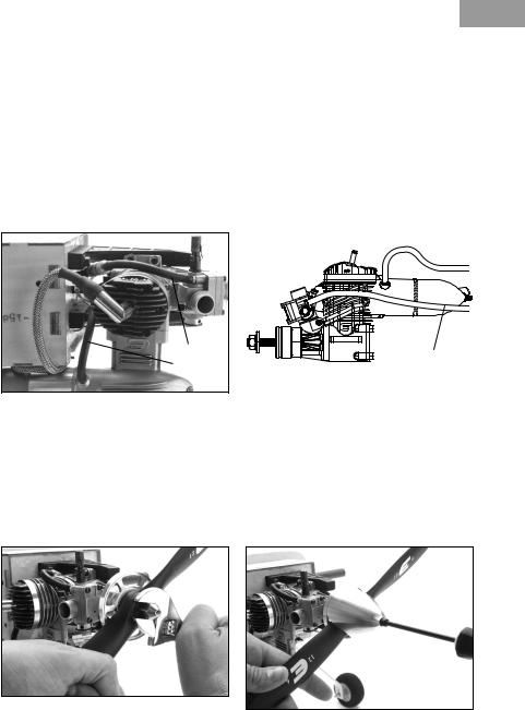
Installing the Muffler
The muffler mounting accessory package includes mounting screws (2), lock washers (2), muffler gaskets (2) and L- wrenches (2).
Connecting the Throttle Linkage
1.Put a lock washer on each of the muffler screws. Push the muffler screws through the cylinder head.
2.Place the muffler gasket over the engine mounting screws.
3.Align the muffler gasket with the exhaust opening and the muffler mounting screws.
4.Tighten the muffler screws.
Important: Tighten the muffler screws after five tanks of fuel. The muffler screws may loosen from heat and vibration.
It is important that you tighten the muffler through-bolt after each of the first three, full tank engine runs. The heat will cause ex-
pansion of the through-bolt and muffler body parts. After the third tightening, no further muffler loosening should occur.
To tighten the muffler through-bolt:
1.Loosen the muffler lock nut.
2.Tighten the muffler through-bolt screw.
3.Tighten the muffler lock nut.
1.Use a secure method to attach the throttle linkage to the throttle arm on the carburetor.
2.Power on the transmitter and receiver.
3.Move the throttle stick to the middle stick position.
4.Adjust the throttle arm so the arm is 90 degrees to the throttle pushrod.
5.Center the throttle servo. Install a servo arm with a hole 11mm (7/16 in) from the center of the arm.
6.Use a clevis to attach the throttle linkage to the servo arm.
6
11mm
1.5mm
Adjusting the Throttle Opening
1.Lower the throttle and center the throttle trim.
2.Adjust the length of the throttle linkage until the throttle is open 1mm.
3.Move the throttle stick up to confirm the throttle opens. If the throttle does not open, reverse the throttle channel in your transmitter.
EN
4.Move the throttle stick and throttle trim down to confirm the throttle closes.
5.If you reversed the throttle channel in your transmitter and you are using a 2.4GHz radio system, you must re-bind your radio system to set the correct failsafe position.
Attaching the Fuel Lines
Fuel Line
Vent Line
1.Connect medium diameter Viton® fuel line to the carburetor and the fuel tank supply line.
2.Connect medium diameter Viton fuel line to the muffler pressure nipple and the fuel tank vent line.
Vent Line
Fuel Line
RECOMMENDED PROPELLERS
10 x 6–13 x 8 (12x6 has tested to be the best performer with this engine although the performance is very good throughout the recommended range)
Attaching the Propeller and Spinner
1.Remove the prop nut and prop washer from the crankshaft.
2.Install the spinner backplate, followed by the propeller, prop washer and prop nut.
3.Cover the propeller with a cloth and use an adjustable wrench to tighten the prop nut.
4.Install the spinner cone. Make sure the spinner cone is not touching the propeller. Trim the propeller opening if necessary.
5.Tighten the spinner screw(s) to secure the spinner cone.
7

EN
Connecting the Electronic Ignition
The Evolution Electronic Ignition Assembly is designed and engineered specifically for the small block engine series. It is smaller and lighter so it fits into tighter spaces of the airplanes the engines are designed to power. The battery voltage required is between 4.8v (4-cell Ni-MH pack) and 8.4V (2S Li-Po battery) and no voltage regulators are needed with any of these batteries. We recommend a 2S Li-Fe battery (such as the Team Orion® Avionics Li-Fe Receiver Pack 1300mAh 6.6V (ORI60503)) and we have done extensive testing with these packs. The maximum amp draw at full throttle is 450mAh, and our more typical average has been between 250–300mAh.
The assembly consists of:
•Ignition module with battery connector, ignition sensor connector, tachometer readout connector and spark plug connector.
•Ignition sensor (already attached to your engine)
•Sensor magnet (already installed in the prop drive hub of your engine)
Mounting Your Electronic Ignition
•You can mount the unit in any orientation and place that is convenient for your installation. The module is sized to conveniently fit into the tank compartment of most 46–50 sized airplanes alongside or underneath the recommended 6–8 oz fuel tanks. You can also mount it to the firewall or under the engine firewall extension if your airplane is so equipped. Keep in mind that it should be mounted away from the heat of the muffler.
•Secure the ignition module to your chosen location with foam padding to provide vibration isolation. We typically mount it conveniently with tie wraps after wrapping the ignition in lightweight 1/4-inch foam rubber.
•You may need to route both the spark plug connector wire and the ignition sensor wire through the firewall so be sure to plan ahead and provide adequate sized holes that will allow you to pull either the ignition sensor connector or the spark plug cap connector through the holes for later ignition removal.
•Mount a good quality radio receiver type switch between the ignition unit and the battery. Mount this switch in a convenient place on the outer fuselage close to the front of the airplane to make it easy to turn the ignition on and off. Being able to easily shut off the ignition is an important safety consideration.
•Connect the ignition sensor wire to the ignition module. The sensor wire will only fit into one of the connectors so you cannot connect it wrong.
•Connect the ON/OFF switch to the battery connector lead of the ignition module. This connector is the red connector.
•If desired you can connect either the separately available tachometer readout or the included Evolution/Spektrum Telemetry
Adapter Cable (EVOA107) to the tachometer readout connector. Plug the other end of the adapter cable into your telemetry module’s rpm input port.
•Connect the spark plug connector to the spark plug. This adapter has a push on and rotate clockwise 1/8 turn locking mechanism to insure a solid connection.
Make sure you charge your ignition battery and are now ready to operate your electronic ignition with the engine.
8

Fuel
This engine requires a mix of 20:1 gas to oil lubricant ratio to operate and last a long time. The bronze bearing at the bottom end of the conrod depends upon this lube ratio to operate properly. Do not go higher than a 20:1 gas/oil ratio or the warranty on your engine will be voided.
To properly mix the fuel add 6.75 oz of good quality 2-stroke oil to one gallon (or 53 mL of oil to one liter) of 87–93 octane fuel.
EN
(EVOX1001Q Evolution 2-stroke oil is recommended) We prefer to add the oil first to our fuel container and to add the gasoline second. This helps to insure a good mixture of the oil with the fuel at the outset.
We have tested our own Evolution 2-stroke oil,
Valvoline, Shell, RedLine and Husqvarna oils.
Other quality 2-stroke oils should work as well. Do not use Amsoil synthetic oil in any form.
Fuel Delivery System
It is very important to properly construct your fuel supply system to the engine to avoid operating problems with our engine. Our experience has shown that many seem-
ingly engine related operating problems are in fact fuel delivery problems, not engine related problems.
Fuel Filtering - Because of the incredibly small amount of fuel that is being used by this engine, filtration of the fuel is mandatory in three different spots in the system:
1.Between the fuel jug and the tank
2.Within the fuel tank itself (with a filtered clunk EVOA106)
3.Between the fuel tank and carburetor (with an in-line fuel filter EVOA105.
Both of these filters (2 and 3) are included in the engine package.
Tank Location - Because muffler pressure is used to provide the pressurization to the fuel regulating and metering carburetor, the tank still needs to be mounted in line with
the carburetor, and as close to the rear of the engine as possible. Care taken in mounting the tank as described will provide trouble free operations in all flight attitudes.
Tank Choice and Construction – Choose a tank between 6–8 oz (170–240 mL). These tanks will yield 17 minutes (for the smaller tank) to 24 minutes (for the larger tank) of full throttle flying time.
The clunk will not move around well if the tank is smaller than 6 oz (170mL). Any tank larger than 8 oz (240mL) will result in carrying extra weight to no benefit (unless you like to fly for a long time).
•Ensure you use a tank stopper made for use with gasoline and/or smoke oil.
•We suggest a three-line tank system; one for the line to the carburetor with the clunk attached internally, one for the muffler pressure to the tank, and one dedicated to fueling/defueling the tank. We try to avoid the T-fittings and other inline valves because they can be a possible source of air/fuel leaks.
•Ensure you use the provided Viton tubing in all the plumbing of the tank, externally and internally.
•Ensure you use the included felt filter clunk inside the fuel tank.
•Ensure you use the included inline filter between the tank and the carburetor.
•Ensure there is a good seal system for the dedicated fueling/defueling line. We highly recommend the HAN116 Fuel Filler
Assembly for its sleek look and ease of use when installed on your airplane.
9

EN
Engine Break-in
Your new engine needs to be broken-in to ensure a long life of all the components. The piston and liner construction piston and liner construction is true ABC (Aluminum piston, Brass Chromed liner), which requires a specific break-in procedure that cannot be fully accomplished with bench runs.
Because the ABC piston and liner rely on the close fit of the piston to the liner to provide the compression seal, the engines are built with a taper to the liner that requires the piston to match the taper during the break-in process. For this to be accomplished, this process requires repeated heating and cooling cycles, and must be done at a needle setting that is only slightly rich of peak.
Breaking in an ABC piston and liner by running it rich does not provide the necessary parts growth to accomplish the needed piston and liner fitting. Using a rich needle setting does not allow for proper expansion of the liner, resulting in the connecting rod receiving the full force of the piston when it moves past Top Dead Center (TDC). Allowing the engine to heat up will expand the liner and reduce the load on the connecting rod, ensuring a proper engine break-in.
Doing the break-in with a light load on the engine (e.g. a smaller than normal propeller) makes this task much easier. Please follow the steps below to ensure a successful experience.
1.Do the break-in process mounted on your airplane and in the air.
2.Use a 10 x 6 prop for your break-in process.
This provides a light load, and high rpm that when matched with the heat of the engine will break-in the engine properly.
3.Use the proper recommended fuel with a 20:1 gas to oil ratio.
4.The proper break-in flight procedure is to fly the airplane at full throttle through a series of figure eight maneuvers (i.e. Cuban Eight). These maneuvers in particular benefit the engine because when climbing the additional load on the engine will increase the temperature and when diving the airplane the lighter load and higher rpm will decrease the temperature, thus providing the heating/cooling cycles required for the break-in process.
5.Run two full tanks with the 10 x 6 prop and then move to an 11 x 6 prop and repeat the next two tanks.
6.You should now be ready to put on any of the larger props and enjoy your engines full performance.
Do not worry about an engine setting being too rich during this process. When set correctly, the engine will occasionally sound as if it is misfiring (which it is). During the climbing maneuvers this should go away and might return during the diving maneuvers. If it does not go away during the climbs then land and adjust the high-speed needle by 1–2 clicks to the leaner position and take off and fly again. Enjoy the break-in process—you are doing a lot of flying.
10
EN
Baseline Needle Valve Settings
Your engine comes from the factory with the needles set at the first run baseline settings
(High-Speed: 2 1/4 turns out, Low-Speed: 5 3/8 turns out). No adjustment is necessary.
If you find you need to move the carburetor back to the baseline settings follow the procedure below.
Tip: The O-ring seal on both needle valves is very tight and it can make the first adjustments of your engine settings difficult. If you find the seal too tight, the best method to free it up is to actually open (counterclockwise) the needle valve a couple of turns before trying to turn the needle in (clockwise).
Low-Speed Needle Valve Setting
The low-speed needle valve should be set
5 3/8 turns from closed when the carburetor barrel is completely closed. The proper way to determine this is to:
1.Disconnect your throttle arm from the throttle pushrod. Insert the included 1.5mm needle valve extension into the carburetor and close the barrel until it is stopped by the extension. The needle valve extention establishes a 1.5mm opening as a baseline for adjusting the low-speed needle.
2.While holding the throttle arm turn the low speed needle clockwise until you feel it trying to force the throttle arm to move and open the carburetor barrel. Be careful here and do not force it past this point.
3.Turn the low speed needle valve counterclockwise (open/richen) by 5 3/8 turns. This setting will be within +/– 1/16 of a turn from a proper low-speed needle valve setting.
4.Reconnect your throttle pushrod to the throttle control arm.
High-Speed Needle Valve Setting
The baseline high-speed needle valve setting for initial start-up is 2 1/4 full turns from closed. The proper way to determine this is to:
1.Turn the high speed needle valve clockwise until you reach its seat. Do not force it past this point because you can damage the needle and/or the needle seat.
2.Turn the high speed needle valve counterclockwise 2 full turns. This setting will be rich by 1/4 to 1/2 turn but it will insure an easy first start.
3.Our experience has been that the engine likes to run between 1 1/2 and 1 3/4 turns open once fully broken-in.
Starting and Operating the 10GX Engine
Now that you have the baseline needle valve settings you are ready to start your engine for the first time. With the 10GX it is very important to allow the temperature to stabilize above 170°F (75°C) before making any adjustments; adjusting prior to the engine warming up will lead you to inaccurate settings. As the engine warms up you will notice the rpms naturally rising.
If you do not have a temp gun or have sensors installed on your engine then allow the engine to run at half throttle for at least 45 seconds before attempting to set the high-speed needle. If you have accurately set the lowspeed needle as described you should not need to adjust it.
Priming
1.Make sure your ignition is off.
2.Open the throttle fully and either by holding a finger over the carburetor intake or the muffler exhaust flip the propeller 4 times.
3.Remove your finger from either the carburetor or muffler exhaust and flip the engine another 6 times.
4.Close the carburetor completely with your throttle stick and then open it two detents from closed. This will allow the engine to start at a high throttle setting.
Because each fuel system and installation is slightly different you may find the need to modify the above procedure for your
individual setup. The above procedure should
work for most installations.
11

EN
Starting and Running the Engine
Until the engine is broken in use an electric starter to start the engine. Once it is fully broken in it can be started by hand but it is easier and safer to start the engine with an electric starter.
1.Turn on the ignition.
2.Rotate the propeller in a backwards direction against compression.
3.Push the starter firmly against the nose cone and engage. The engine should start relatively quickly, within 1-2 seconds. Once the engine starts disengage the starter.
4.Let the engine run at mid-throttle for 45 seconds to stabilize the temperatures.
a.If the engine doesn’t start quickly disengage the starter. Continuously running the starter can flood the engine.
b.Check to make that fuel is moving through the carburetor system.
c.If the engine appears not to have any fuel, repeat the priming procedure above.
d.Repeat 1–4 of Starting and Running the
Engine.
High-Speed Needle Adjustment
Because of the small amount of fuel actually needed for this engine, needle adjustments need to be made in small increments. It may take 5 seconds or more before you will notice a running change in your engine after making it. Be patient. Use a tachometer, this is a very important part of properly setting your highspeed needle valve.
The procedure below is for ground setting the needles prior to flight. The final adjustments need to be made after noting the performance in the air.
1.With engine started and warmed up, open the throttle fully and note the rpm. Listen to the engine.
a.If the engine occasionally mis-fires but maintains a fairly constant rpm after 5 seconds, your engine is rich. Reduce the throttle to idle and turn in (clockwise) the high-speed needle 2 clicks. Repeat this until the engine stops mis-firing.
b.If the engine does not mis-fire and the rpm steadily decreases from the highest rpm achieved when you opened the throttle, it is lean. Reduce the throttle to idle and open (counterclockwise) the high-speed needle 2 clicks. Repeat this until the engine maintains the rpm achieved when the throttle is wide open
Your goal here is to achieve a good transition between high and low speed, and that the high-speed rpm will be steady on the ground.
2.Fly your aircraft for the in-air testing.
a.During flight, if the engine seems to slow down or sag when climbing, your engine is running slightly lean. Land the airplane and open the high-speed needle valve 2 clicks and take-off again.
b.During flight, if you hear the engine misfiring occasionally in level flight, this is an indication it is running too rich. Land the airplane and close the high-speed needle valve 2 clicks and take-off again.
c.Repeat the above process until your engine performance is steady and repeatable. This high-speed needle setting should not change more than
+/– 1–2 clicks in the future when using the same propeller. If it does, something is wrong in the fuel delivery system and should be investigated.
If you are using onboard telemetry and have a temperature monitor on the head of your engine, your readings should be between 300°F (150°C) and 330°F (165°C). See the section on adding a temperature monitor to your engine for the proper positioning of your sensor.
12

Low-Speed Needle Adjustment
If you have properly set the idle need, the low-speed setting should be within 1/16th of a turn from perfect. Remember we are talking about minute amounts of fuel going through the carburetor, any adjustments you now make to the idle needle should be very, very small.
Take into consideration the length in service
(e.g. break-in time) and the size of propeller you are using. In the beginning using a smaller propeller, early in the break-in process, you will not be able to achieve an idle much below
2800 rpm. The larger the propeller, the lower your idle rpm will be, and the more broken in your engine is will allow a lower idle rpm (13 x 6 should be about 22–2300 rpm).
Your engine will idle at low-speed needle settings from far to0 rich to far too lean without any damage so the quality of the idle is not a good indicator of the proper low-speed
needle settings. The transition from idle to full throttle will be used to determine the position of the low-speed needle.
1.With engine started and warmed up, open the throttle fully then reduce to idle and note the rpm. Listen to the engine.
2.Let the engine idle for ten seconds and then rapidly advance the throttle to full open. One of three things will occur:
a.The engine responds instantaneously.
Your low speed needle is set perfectly.
Now use your throttle trim to achieve the lowest reliable idle.
EN
b.The engine slowly accelerates to full throttle. This indicates the low speed needle is set two rich and that fuel is building up in the crankcase. Shut the engine off and lean (clockwise turn) the low speed idle screw by an amount equal to the thickness of the screwdriver blade you are using to make the adjustment. Restart the engine and repeat steps 1 and 2.
c.The engine stutters or stops on it way to full throttle. This indicates the low speed needle is set too lean. With the engine off, richen (counter-clockwise turn) the low speed idle screw by an amount equal to the thickness of the screwdriver blade you are using to make the adjustment. Restart the engine and repeat step
1 & 2.
3.Once you have achieved the instantaneous throttle transition your low-speed needle is set perfectly. Now go back and recheck your high-speed needle valve setting. There is some interaction between the two needles so you might need to do this process (HS and LS needle setting) a couple of times.
Patience here will reward you with an easy to use engine. Don’t try to do this too quickly.
4.Once you have achieved the instantaneous throttle transition your low speed needle is set perfectly and you should never have to touch it again regardless of the propeller you try to use.
13

EN
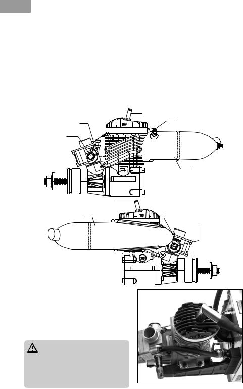
10GX Evolution Engines Specifications
Item |
Disp |
Bore |
Stroke |
Weight |
Crank K |
Cylinder |
Propeller |
|
(c.i.) |
(mm) |
(mm) |
(oz) |
(ISO) |
|
|
EVOE10GX |
.60 |
24.0 |
21.5 |
15.3 |
1/4 x 28 |
ABC |
12 x 6 @ 12,600 rpm |
F

 H
H 

B A |
|
|
|
|
|
|
|
|
|
|
|
|
G |
|
E = height* |
|
|
||||||
|
|
|
|
|
|
|
|
|
|
|
|
|
|
|
|||||||||
|
|
|
|
|
|
|
|
|
|
|
|
|
|
|
|
|
|
|
|
|
|
|
|
|
|
|
|
|
|
|
|
|
|
|
|
|
|
|
|
|
|
|
|
|
|
|
|
|
|
|
|
|
|
|
|
|
|
|
|
|
|
|
|
|
|
|
|
|
F = length |
|
|
|
|
|
|
|
|
|
|
|
|
|
|
|
|
|
|
|
|
|
|
|
|
|
|
|
|
|
|
|
|
|
|
C |
|
|
|
D |
|
|
|
|
|
|
|
|
G= crankshaft thread size |
||
|
|
|
|
|
|
|
|
|
|
|
|
|
|
|
|
|
|
|
H = muffler bolt spacing |
||||
|
|
|
|
|
|
|
|
|
|
|
|
|
|
|
|
|
|
|
|
|
|||
Dimensions |
|
A |
B |
|
|
C |
|
D |
E* |
F |
G |
H |
|||||||||||
|
|
|
|
|
|
|
|
|
|
|
|
|
|
||||||||||
EVOE10GX |
36 |
|
|
|
44 |
|
17.5 |
|
57.4 |
72 |
88.5 |
1/4 x 28 |
37 |
||||||||||
* Height is from engine C/L to top of cylinder head.
Troubleshooting Guide
If the Engine Does Not Start
•Check and use a new spark plug if needed.
•Check fuel lines.
•Check for proper mechanical function by turning the engine over.
•Check that the carburetor is correctly installed.
•Check that the muffler pressure line is attached and free from any bends or blockages.
Mechanical Faults
If the engine cannot be turned over easily
•The most likely cause is the engine is flooded and by turning the engine over you are trying to compress the fuel, not air.
1.Remove the spark plug.
2.Cover the cylinder head with a cloth or paper towel and turn the propeller over to expel all the excess fuel.
3.Replace the spark plug and try starting again.
•A possible cause is the piston in the cylinder is seized: loosen and unscrew the cylinder head bolts.
1.Carefully remove the cylinder liner.
2.Visually examine the piston and cylinder to find the possible cause of the engine’s mechanical problem.
Mechanical repairs must ALWAYS be completed by an authorized Horizon Hobby service center.
Maintenance
After each flying session:
1.Fully drain the fuel from the tank.
2.Start the engine and run it until the fuel is completely run out of the engine.
3.Try starting the engine three more times or until it will no longer fire. This gets all the fuel out of the engine.
If you need additional help or have any questions, please call Horizon’s Support Team. Horizon has trained technicians who are qualified to answer your engine questions.
14
EN
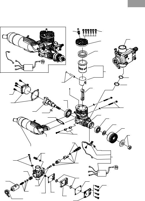
Exploded View |
|
|
|
|
|
|
|
2 |
|
1 |
|
|
|
|
|
3 |
21 |
|
|
|
|
4 |
|
|
|
|
|
|
5 |
|
|
|
|
|
22 |
|
|
6 |
|
|
23 |
|
|
|
|
7 |
|
|
|
|
|
|
|
17 |
|
|
|
|
|
16 |
|
13 |
|
|
|
|
|
|
|
|
|
15 |
|
|
|
|
20 |
14 |
|
|
12 |
|
|
|
|
|
|
||
|
|
41 |
|
11 |
|
|
|
|
|
||
|
|
|
|
|
|
|
|
|
|
|
10 |
|
|
|
|
|
9 |
|
|
|
24 |
|
8 |
|
|
19 |
|
|
|
|
|
|
|
|
|
|
|
35 |
|
|
|
18 |
|
|
|
|
|
|
|
36 |
|
|
|
37 |
|
|
|
|
25 |
|
|
34 |
|
|
|
|
|
|
|
|
|
39 |
|
|
|
|
|
32 |
|
|
31 |
30 |
|
|
|
|
40 |
||
26 |
|
|
|
|
|
33 |
29 |
30 |
|
|
|
|
|
|
|
||
38 |
|
27 |
|
|
|
|
28 |
|
|
|
|
|
|
|
|
|
15

EN
Parts List
# |
Description |
Part |
|
|
|
1 |
Cylinder Head Screws |
EVO40120 |
|
(6) 10GX |
|
2 |
Spark Plug ¼-32 thread |
EVOG10350 |
3 |
Cylinder Head 10GX |
EVOG10103 |
4 |
Cylinder Head Shim: |
EVO060112 |
|
60NX, 10GX |
|
5 |
Cylinder Piston Set 10GX |
EVOG10203 |
6 |
Wrist Pin with Clips: |
EVO052213 |
|
52NX, 60NX, 10GX |
|
7 |
Connecting Rod 10GX |
EVOG10204 |
8 |
Prop Washer & Nut: |
EVO040228 |
|
1/4 x 28 |
|
9 |
Prop Driver 10GX |
EVOG10219 |
10 |
Spacer Washer; |
EVO91225 |
|
120NX, 10GX |
|
11 |
Front Bearing; |
EVO91109 |
|
120NX, 10GX |
|
12 |
Crankcase with index |
EVOG10101 |
|
pin 10GX |
|
13 |
BB, Rear (Open Race): |
EVO052110 |
|
52NX, 60NX, 10GX |
|
14 |
Drive Key; 120NX, 10GX |
EVO91218 |
15 |
Crankshaft 10GX |
EVOG10210 |
16Rear Cover with Gasket: EVOG10102 52NX, 60NX, 10GX
17 |
Back Cover Screw (4) |
EVO40134 |
|
10GX |
|
18 |
Muffler Assy 10GX |
EVOG10601 |
19 |
Muffler Long Screw |
EVO120616 |
|
120NX, 10GX |
|
20 |
Muffler Mounting |
EVO100E46A |
|
Screw Set |
|
# |
Description |
Part |
|
|
|
21 |
Carb Assy 10GX |
EVOG10801 |
22 |
Carb Mounting O-Ring |
EVOG10816 |
23 |
Carb base washer |
EVO46826 |
24 |
Carb Retainer (Drawbar) |
EVOG10129 |
|
10GX |
|
25 |
Evo 10GX Ignition Unit |
EVO10101 |
26 |
Carb Body & Spray Bar |
EVOG10863 |
|
10GX |
|
27 |
Regulator Case |
EVOG10872 |
|
mid-section 10GX |
|
28 |
Regulator Case Top 10GX |
EVOG10874 |
29 |
Regulator Spring 10GX |
EVOG10880 |
30 |
Regulator Gasket Set |
EVOG10875a |
|
10GX |
|
31 |
Regulator Piston Set |
EVOG10876a |
|
10GX |
|
32 |
Carb Barrel 10GX |
EVOG10813 |
33 |
Idle Needle Assy 10GX |
EVOG10810 |
34 |
High Speed Needle |
EVOG10812 |
|
Assembly 10GX |
|
35 |
Hi Speed Needle 10GX |
EVOG10829 |
36 |
Fuel Nipple-12114:A |
EVO100114 |
37 |
Idle Needle Stop |
EVO100825F |
|
Screw-46825F:A |
|
38 |
Throttle Arm |
EVO100864A |
39 |
Carb Barrel Spring 10GX |
EVOG10814 |
40 |
Carb regulator screws |
EVOG12123 |
|
(4) 10GX |
|
41 |
Engine Gasket Set: |
EVO060416 |
|
60NX, 10GX |
|
|
|
|
2 YEAR LIMITED WARRANTY |
or maintenance, (iii) modification of or to any |
What this Warranty Covers - Horizon Hobby, Inc., |
part of the Product, (iv) attempted service by |
(Horizon) warrants to the original purchaser that |
anyone other than a Horizon Hobby authorized |
the product purchased (the “Product”) will be free |
service center, (v) Product not purchased from |
from defects in materials and workmanship for a |
an authorized Horizon dealer, or (vi) Product not |
period of 2 years from the date of purchase. |
compliant with applicable technical regulations. |
What is Not Covered - This warranty is not trans- |
OTHER THAN THE EXPRESS WARRANTY ABOVE, |
ferable and does not cover (i) cosmetic dam- |
HORIZON MAKES NO OTHER WARRANTY OR REP- |
age, (ii) damage due to acts |
of God, accident, RESENTATION, AND HEREBY DISCLAIMS ANY AND |
|
misuse, abuse, negligence, |
commercial use, |
ALL IMPLIED WARRANTIES, INCLUDING, WITHOUT |
or due to improper use, installation, operation |
LIMITATION, THE IMPLIED WARRANTIES OF NON- |
|
16

EN
INFRINGEMENT, MERCHANTABILITY AND FITNESS |
or call 877.504.0233 toll free to speak to a Product |
FOR A PARTICULAR PURPOSE. THE PURCHASER |
Support representative. |
ACKNOWLEDGES THAT THEY ALONE HAVE DETER- |
Inspection or Services - If this Product needs to |
MINED THAT THE PRODUCT WILL SUITABLY MEET |
be inspected or serviced and is compliant in the |
THE REQUIREMENTS OF THE PURCHASER’S IN- |
country you live and use the Product in, please |
TENDED USE. |
use the Horizon Online Service Request submis- |
Purchaser’s Remedy - Horizon’s sole obligation |
sion process found on our website or call Horizon |
and purchaser’s sole and exclusive remedy shall |
to obtain a Return Merchandise Authorization |
be that Horizon will, at its option, either (i) service, (RMA) number. Pack the Product securely using or (ii) replace, any Product determined by Horizon a shipping carton. Please note that original boxes to be defective. Horizon reserves the right to inmay be included, but are not designed to withspect any and all Product(s) involved in a warranty stand the rigors of shipping without additional
claim. Service or replacement decisions are at |
protection. Ship via a carrier that provides track- |
the sole discretion of Horizon. Proof of purchase |
ing and insurance for lost or damaged parcels, as |
is required for all warranty claims. SERVICE OR |
Horizon is not responsible for merchandise until |
REPLACEMENT AS PROVIDED UNDER THIS WAR- |
it arrives and is accepted at our facility. An Online |
RANTY ISTHE PURCHASER’SSOLE AND EXCLUSIVE |
Service Request is available at http://www.hori- |
REMEDY. |
zonhobby.com/content/_service-center_render- |
Limitation of Liability - HORIZON SHALL NOT BE |
service-center. If you do not have internet access, |
LIABLE FOR SPECIAL, INDIRECT, INCIDENTAL OR |
please contact Horizon Product Support to obtain |
CONSEQUENTIAL DAMAGES, LOSS OF PROFITS OR |
a RMA number along with instructions for submit- |
PRODUCTION OR COMMERCIAL LOSS IN ANY WAY, |
ting your product for service. When calling Hori- |
REGARDLESS OF WHETHER SUCH CLAIM IS BASED |
zon, you will be asked to provide your complete |
IN CONTRACT, WARRANTY, TORT, NEGLIGENCE, |
name, street address, email address and phone |
STRICT LIABILITY OR ANY OTHER THEORY OF LI- |
number where you can be reached during busi- |
ABILITY, EVEN IF HORIZON HAS BEEN ADVISED OF |
ness hours. When sending product into Horizon, |
THE POSSIBILITY OF SUCH DAMAGES. Further, in |
please include your RMA number, a list of the |
no event shall the liability of Horizon exceed the |
included items, and a brief summary of the prob- |
individual price of the Product on which liability |
lem. A copy of your original sales receipt must be |
is asserted. As Horizon has no control over use, |
included for warranty consideration. Be sure your |
setup, final assembly, modification or misuse, no |
name, address, and RMA number are clearly writ- |
liability shall be assumed nor accepted for any re- |
ten on the outside of the shipping carton. |
sulting damage or injury. By the act of use, setup |
NOTICE: Do not ship LiPo batteries to Horizon. If |
or assembly, the user accepts all resulting liability. |
you have any issue with a LiPo battery, please |
If you as the purchaser or user are not prepared to |
contact the appropriate Horizon Product Support |
accept the liability associated with the use of the |
office. |
Product, purchaser is advised to return the Prod- |
Warranty Requirements - For Warranty consider- |
uct immediately in new and unused condition to |
ation, you must include your original sales receipt |
the place of purchase. |
verifying the proof-of-purchase date. Provided |
Law - These terms are governed by Illinois law |
warranty conditions have been met, your Product |
(without regard to conflict of law principals). This |
will be serviced or replaced free of charge. Service |
warranty gives you specific legal rights, and you |
or replacement decisions are at the sole discretion |
may also have other rights which vary from state |
of Horizon. |
to state. Horizon reserves the right to change or |
Non-Warranty Service - Should your service not |
modify this warranty at any time without notice. |
be covered by warranty, service will be completed |
WARRANTY SERVICES |
and payment will be required without notification |
Questions, Assistance, and Services - Your local |
or estimate of the expense unless the expense |
hobby store and/or place of purchase cannot pro- |
exceeds 50% of the retail purchase cost. By sub- |
vide warranty support or service. Once assembly, |
mitting the item for service you are agreeing to |
setup or use of the Product has been started, you |
payment of the service without notification. Ser- |
must contact your local distributor or Horizon di- |
vice estimates are available upon request. You |
rectly. This will enable Horizon to better answer |
must include this request with your item submit- |
your questions and service you in the event that |
ted for service. Non-warranty service estimates |
you may need any assistance. For questions or |
will be billed a minimum of ½ hour of labor. In ad- |
assistance, please visit our website at www.hori- |
dition you will be billed for return freight. Horizon |
zonhobby.com, submit a Product Support Inquiry, |
accepts money orders and cashier’s checks, as |
17

EN
well as Visa, MasterCard, American Express, and
Discover cards. By submitting any item to Horizon for service, you are agreeing to Horizon’s Terms and Conditions found on our website http://www. horizonhobby.com/content/_service-center_ren- der-service-center.
Warranty and Service Contact Information
NOTICE: Horizon service is limited to Product compliant in the country of use and ownership. If non-compliant product is received by Horizon for service, it will be returned unserviced at the sole expense of the purchaser.
|
Horizon Hobby |
Address |
Phone Number/Email Address |
|
|
|
|
|
|
|
Horizon Service Center |
|
877-504-0233 |
|
|
(Electronics and |
4105 Fieldstone Rd |
Online Repair Request: visit |
|
United States |
engines) |
www.horizonhobby.com/service |
||
of America |
|
Champaign, Illinois, |
|
|
Horizon Product |
|
|||
61822 USA |
877-504-0233 |
|||
|
||||
|
Support |
|
||
|
|
productsupport@horizonhobby.com |
||
|
(All other products) |
|
||
|
|
|
||
|
|
|
|
|
|
|
Units 1-4 , Ployters |
|
|
United |
|
Rd, Staple Tye, |
+44 (0) 1279 641 097 |
|
Horizon Hobby Limited |
Harlow, Essex, |
|||
Kingdom |
sales@horizonhobby.co.uk |
|||
|
CM18 7NS, United |
|||
|
|
|
||
|
|
Kingdom |
|
|
|
|
|
|
|
|
|
Christian-Junge- |
|
|
Germany |
Horizon Technischer |
Straße 1 |
+49 (0) 4121 2655 100 |
|
Service |
25337 Elmshorn, |
service@horizonhobby.de |
||
|
||||
|
|
Germany |
|
|
|
|
|
|
|
|
|
11 Rue Georges |
|
|
France |
Horizon Hobby SAS |
Charpak |
+33 (0) 1 60 18 34 90 |
|
77127 Lieusaint, |
infofrance@horizonhobby.com |
|||
|
|
|||
|
|
France |
|
|
|
|
|
|
Compliance Information for the European Union

 Declaration of Conformity (in accordance with ISO/IEC 17050-1)
No. HH2012092301
Product(s): EVO 10cc (.60 cu. in.) Gas RC Engine Item Number(s): EVOE10GX
The object of declaration described above is in conformity with the requirements of the specifications listed below, following the provisions of the European EMC Directive 2004/108/EC:
EN55022:2010
EN55024:2010
Signed for and on behalf of: |
|
Horizon Hobby, Inc. |
Steven A. Hall |
Champaign, IL USA |
Executive Vice President and Chief Operating Officer |
September 23, 2012 |
International Operations and Risk Management |
|
Horizon Hobby, Inc. |
Instructions for disposal of WEEE by users in the European Union
This product must not be disposed of with other waste. Instead, it is the user’s responsibil-
 ity to dispose of their waste equipment by handing it over to a designated collections point for the recycling of waste electrical and electronic equipment. The separate collection and recycling of your waste equipment at the time of disposal will help to conserve natural resources and ensure that it is recycled in a manner that protects human health and the environment. For more information about where you can drop off your waste equipment for recycling, please contact your local city office, your household waste disposal service or where you purchased the product.
18

DE
HINWEIS
Alle Anweisungen, Garantien und anderen zugehörigen Dokumente können im eigenen Ermessen von Horizon Hobby, Inc. jederzeit geändert werden. Die aktuelle Produktliteratur finden Sie auf horizonhobby.com unter der Registerkarte „Support“ für das betreffende Produkt.
Spezielle Bedeutungen
Die folgenden Begriffe werden in der gesamten Produktliteratur verwendet, um auf unterschiedlich hohe Gefahrenrisiken beim Betrieb dieses Produkts hinzuweisen:
HINWEIS: Wenn diese Verfahren nicht korrekt befolgt werden, können sich möglicherweise Sachschäden UND geringe oder keine Gefahr von Verletzungen ergeben.
ACHTUNG: Wenn diese Verfahren nicht korrekt befolgt werden, ergeben sich wahrscheinlich Sachschäden UND die Gefahr von schweren Verletzungen.
WARNUNG: Verfahren können bei nicht ordnungsgemäßer Durchführung möglicherweise Schäden an Eigentum, Kollateralschäden UND schwere Verletzungen bis zum Tot ODER höchstwahrscheinlich oberflächliche Verletzungen verursachen.
WARNUNG: Lesen Sie die GESAMTE Bedienungsanleitung, um sich vor dem Betrieb mit den Produktfunktionen vertraut zu machen. Wird das Produkt nicht korrekt betrieben, kann dies zu Schäden am Produkt oder persönlichem Eigentum führen oder schwere Verletzungen verursachen.
Dies ist ein hochentwickeltes Hobby-Produkt. Es muss mit Vorsicht und gesundem Menschenverstand betrieben werden und benötigt gewisse mechanische Grundfähigkeiten. Wird dieses Produkt nicht auf eine sichere und verantwortungsvolle Weise betrieben, kann dies zu Verletzungen oder Schäden am Produkt oder anderen Sachwerten führen. Dieses Produkt eignet sich nicht für die Verwendung durch Kinder ohne direkte Überwachung eines Erwachsenen. Versuchen Sie nicht ohne Genehmigung durch Horizon Hobby, Inc., das Produkt
zu zerlegen, es mit inkompatiblen Komponenten zu verwenden oder auf jegliche Weise zu erweitern. Diese Bedienungsanleitung enthält Anweisungen für Sicherheit, Betrieb und Wartung. Es ist unbedingt notwendig, vor Zusammenbau, Einrichtung oder Verwendung alle Anweisungen und Warnhinweise im Handbuch zu lesen und zu befolgen, damit es bestimmungsgemäß betrieben werden kann und Schäden oder schwere Verletzungen vermieden werden.
ACHTUNG: Dieses Produkt kann bei dem Betrieb extrem heiß werden was zu
Verbrennungen führen kann.
Nicht geeignet für Kinder unter 14 Jahren. Dies ist kein Spielzeug.
Sicherheitswarnungen
Modellmotoren haben eine erhebliche Leistung, die bei unsachgemäßer Verwendung eine Gefährdung darstellen kann. Nutzen Sie bei dem Betrieb immer den gesunden Menschenverstand und beachten alle Sicherheitshinweise bei dem Umgang mit dem Motor, oder allen Tätigkeiten in diesem Zusammenhang. Das nicht befolgen der Sicherheitsbestimmungen kann zu ernsthaften Personenund Sachbeschädigungen führen.
•Stellen Sie immer sicher dass Zuschauer, insbesondere Kinder, mindestens 9,90 Meter entfernt sind wenn Sie den Motor laufen lassen.
•Stellen Sie vor JEDEM Flug sicher, dass der Propeller fest mit der Kurbelwelle verbunden ist und alle Halter/Befestigungen sicher angezogen/befestigt sind. Verwenden Sie zum sichern von Schrauben und Muttern blauen Schraubensicherungslack.
•Halten Sie Kleinteile immer aus der Reichweite von Kindern, da diese verschluckt werden können.
•Sichern Sie immer das Flugzeug bevor Sie den Motor starten.
•Halten Sie immer das Gesicht und den Körper weg vom Propellerkreis wenn Sie den Motor
19

DE
starten oder wenn er läuft.
•Stellen Sie sich immer hinter den Propeller wenn Sie Einstellungen am Vergaser vornehmen.
•Tragen Sie immer eine Schutzbrille beim Starten oder Laufen lassen des Motors.
•Bewahren Sie ihren Kraftstoff immer an einem sicheren Ort weit weg von möglicher Funkenbildung, Hitze oder zündfähigen Stoffen auf.
•Stellen Sie immer sicher, dass das Luftfahrzeug korrekt gesichert ist und sich bei Motorstart nicht bewegen/anrollen kann.
•Führen Sie nach den Einstellungen vor dem Erstflug den Bindevorgang erneut aus.
•Stellen Sie immer sicher dass die Failsafeeinstellung des Gaskanal auf Motor aus/
Leerlauf steht.
•Führen Sie immer vor dem Flug einen Reichweitentest durch.
•Unterbrechen Sie die Kraftstoffversorgung (durch trennen oder abdrücken der
Kraftstoffleitung) oder schließen Sie mit Gasgestänge die Vergaserdrosselklappe um den Motor zu stoppen.
•Gebrauchen Sie niemals Ihre Hände, Finger oder andere Körperteile um den Propeller zu stoppen.
•Werfen Sie niemals etwas in den Propeller um ihn zu stoppen.
•Lassen Sie niemals den Motor über losen Untergrund wie Sand oder Kies laufen, damit nicht die Gefahr besteht dass der Motor kleine Teile unkontrolliert hochschleudert.
•Tragen Sie niemals bei dem Betrieb des Modells lose Kleidung oder ein loses Nackenband/
Umhängegurt, da sich diese Teile im Propeller verfangen können.
•Führen Sie niemals bei Betrieb oder Umgang mit dem Motor lose Gegenstände wie
Schraubendreher, Stifte, etc.. in Ihren Taschen. Diese könnten in den Propeller fallen.
•Lassen Sie niemals Kraftstoff in Berührung mit Mund oder Augen kommen da dieser giftig ist.
•Lagern Sie Kraftsoff in eindeutig bezeichneten Behältnissen ausserhalb der Reichweite von Kindern.
Sicherheitsrichtlinien
•Montieren Sie den Motor korrekt auf einer geeigneten Werkbank oder einem qualitativ hochwertigen Motorträger.
•Verwenden Sie immer Propeller mit der richtigen Größe und Steigung. Sehen Sie dazu in die Propellerliste in dieser Anleitung.
•Überprüfen Sie immer vor der Montage des Propellers dass dieser einwandfrei gewuchtet ist. Das nichtbeachten könnte zu Motorschäden oder zu Schäden am Flugzeug führen.
•Verwenden Sie immer falls möglich einen Elektrostarter.
•Verwenden Sie keine Propeller die Knicke, Risse, Brüche oder sonstige Beschädigungen aufweisen.
•Lassen Sie den Motor nur in gut belüfteten Bereichen laufen. Modellmotoren produzieren giftige Kohlenmonoxid Abgase.
•Lagern Sie Kraftstoff nur in kühlen trockenen Orten. Lassen Sie Kraftstoffbehälter nicht in direkten Kontakt mit Beton kommen, da der Kraftstoff dadurch Feuchtigkeit aufnehmen könnte.
•Entsorgen Sie immer verantwortungsvoll Kraftstoff der durch Kondensation Feuchtigkeit (Wasser) aufgenommen hat.
•Schütten Sie niemals ungebrauchten Kraftstoff aus dem Tank in den Kanister.
•Modifizieren, verändern und reparieren Sie niemals Propeller.
•Hantieren Sie nicht mit Modellmotoren, Schalldämpfern, Auspuffen oder Resorohren bis diese vollständig abgekühlt sind. Diese können bei Betrieb extrem heiß werden.
Einleitung
Wir beglückwünschen Sie zum Kauf Ihres ersten Evolution-Small Block-Benzinmotors unserer neuen Serie. Sämtliche Evolution-Benzinmotoren sind dafür ausgelegt, Ihnen ab dem ersten Tag hervorragende Leistung zum Bruchteil Ihrer vorherigen Betriebskosten zu geben. Wir haben jeden einzelnen Motor mit äußerster Sorgfalt konstruiert und geprüft, um einen problemlosen Betrieb ohne Kompromisse in der Leistung oder Langlebigkeit einzugehen. Dieses Handbuch führt Sie, wenn Sie es lesen und befolgen, durch einfache Schritte zu einer erfolgreichen Anwendung. Herzlich willkommen bei der Evolution-Produktfamilie.
20
DE
Small Block-Benzinmotorkonstruktion
Begonnen haben wir mit dem vielfach bewährten 60NX-Glühkerzenmotor, der von Tausenden von Kunden auf der ganzen Welt eingesetzt wird; jetzt haben wir unsere Erfahrung in das Bereich der Benzinmotoren eingebracht, um Ihnen ein vollständiges Paket, hervorragende Leistung und niedrige Betriebskosten liefern zu können.
Schritt 1 Beginn mit einem hervorragenden Motor. Der 60NX wurde im Juli 2009 erstmalig angekündigt und seitdem an Tausende von Anwendern erfolgreich verkauft; er liefert exzellente Leistung.
Schritt 2 Konstruktion eines neuen, zuverlässigen Vergasersystems für einen problemlosen Betrieb beim Anwender. Dieser neue Vergaser, der bereits mit bewährter Technologie aufwartet, wurde modifiziert, um in den verfügbaren Bauraum vor dem Zylinder
zu passen und um die speziellen Anforderungen eines benzinbetriebenen Motors zu erfüllen. An der Vorderseite des Vergasers befindet sich ein durch den Druck im Kurbelgehäuse angetriebenes Regelsystem. Dieses System umfasst einen über den
Schalldämpfer unter Druck gesetzten Tank, der den Kraftstoff in allen Flughöhen richtig zumisst. Ein neues Katzenaugen-Kraftstoffmesssystem wurde hinzugefügt, um in den unteren und mittleren Gasstellungen für mehr Steuerbarkeit zu sorgen.
Schritt 3 Konstruktion eines eigenen Schalldämpfersystems zur Abfuhr der zusätzlichen Hitze und Wärmeausdehnung des verbrannten Benzingemisches im Vergleich zu einem Glühsystem. Diese Änderungen umfassten das Vergrößern des Schalldämpfervolumes einschließlich einer wesentlich größeren Schalldämpfer-Durchgangsschraube zur Ableitung von Hitze und Spannung sowie die Vergrößerung des Schalldämpferausgangs zur Minimierung des Rückstaus, ohne die Schalldämpfung zu beeinträchtigen.
Schritt 4 Konstruktion von Betriebszubehör zur Verbesserung des Anwendererlebnisses.
Während unseres umfangreichen, 2-1/2-jährigen Testprogramms haben wir eine Reihe von neuen Techniken und auch von Hindernissen entdeckt, die typisch für benzinbetriebene Kleinmotoren sind.
•Da die Menge des verbrauchten Kraftstoffs nur etwa ein Drittel der eines vergleichbaren Glühkerzenmotors ist, sind Konstruktion und Zuverlässigkeit des Kraftstoffversorgungssystems zum Vergaser dreimal so kritisch. Mikroskopisch kleine Schmutzteilchen, die problemlos durch die größeren Querschnitte eines Glühkerzenmotor-Vergasers fließen, richten in einem Benzinsystem verheerende Schäden an. Dieses Schmutzproblem lösen wir durch einen Qualitäts-
Leitungsfilter wie z. B. unseren Leitungsfilter (EVOA105). Unser Motor ist mit diesem Filter ausgerüstet.
•Das Gleiche gilt für Luftblasen aus dem Tank oder für kleine Lecks in der
Benzinleitung; was problemlos durch einen Glühkerzenmotor-Vergaser geht, wird in einem Benzinsystem nicht toleriert, da die Luftblasen dreimal soviel Wirkung zeigen wie vorher. Wir haben einen exzellenten Filzfilterklotz entwickelt und verbaut, der Luftblasenbildung in der Benzinleitungen verhindert. Dieser Filzklotz ist für einen zuverlässigen und erfolgreichen Betrieb äußerst wichtig. Unser Motor ist mit diesem Filter ausgerüstet.
•Wir haben herausgefunden, dass hohe Schalldämpfertemperaturen die normalen Tygonleitungen (die erste Wahl für Benzinmotoren) innerhalb von
Minuten zerstören würde. Wir haben herausgefunden, dass Neoprenleitungen den hohen Temperaturen zwar widerstehen, sich aber zu schnell degenerieren würden; darum haben wir Viton-Leitungen der richtigen Größe verwendet
(Benzinleitung EVOA104). Sie widerstehen nicht nur den hohen Temperaturen, ihre Widerstandsfähigkeit ist auch wesentlich größer als die von Tygon oder Neopren. Ein weiterer Vorteil dieser Leitungen besteht darin, dass sie ohne zusätzliche Drähte oder Schlauchschellen gut an den Benzinleitungsanschlüssen halten. Ihr Motor ist mit einem Satz dieser Leitungen ausgerüstet.
21
DE
Mitgelieferter Inhalt
MOTOR |
OPTIONALE ARTIKEL |
||
• |
Schalldämpfer (EVO10601) |
• |
Drehzahlmesser (HAN156) |
• |
Schalldämpferschrauben, -dichtung |
• Propeller 10 x 6 (EVO10060) für das |
|
|
(EVO100E46A) |
|
Einlaufen; 12 x 6 (EVO12060) für Normalflug |
• |
Zündkerze (EVOG10350) |
• |
EVOM1 Getunter |
• |
Evolution/Spektrum Telemetrie-RPM- |
|
Hochleistungsschalldämpfer: EVO46-60 |
|
Adapterkabel (EVOA107) |
|
|
•Med. Kraftstoffleitung (EVOA104)
•Leitungsmontierter Kraftstofffilter (EVOA105)
•Tankmontierter Filzfilter/Klotz (EVOA106)
|
Zündkerze |
Kraftstoffnippel |
Schalldämpfernippel |
|
|
Nadel für |
|
hohe Drehzahl |
|
|
Schalldämpfer |
|
Zündkerze |
|
Schalldämpfer |
Nadelanschlag |
|
Nadel für niedrige |
||
|
||
|
Drehzahl |
Gasarm |
Einbau des Motors
1.Motorträger am Brandschott des Flugzeugs befestigen. Die Motorträgerschrauben im Brandschott festziehen.
2.Den Motor gemäß der Angaben des
Flugzeugherstellers am Motorträger befestigen.
WARNUNG: Ziehen Sie vor jedem Flug alle Motorbefestigungsschrauben nach. Wenn Sie die Motorbefestigungsschrauben nicht nachziehen, können sie sich durch die Vibrationen lockern und der Motor kann sich vom Rumpflösen.
22
 Loading...