

Page 1
62 GXI
Evolution® Gas Engines
Page 2

NOTICE
All instructions, warranties and other collateral documents are subject to change at the sole
discretion of Horizon Hobby, LLC. For up-to-date product literature, visit horizonhobby.com
and click on the support tab for this product.
MEANING OF SPECIAL LANGUAGE
The following terms are used throughout the product literature to indicate various levels
of potential harm when operating this product:
NOTICE: Procedures, which if not properly followed, create a possibility of physical property
damage AND a little or no possibility of injury.
CAUTION: Procedures, which if not properly followed, create the probability of physical
property damage AND a possibility of serious injury.
WARNING: Procedures, which if not properly followed, create the probability of property
damage, collateral damage, serious injury or death OR create a high probability of
superficial injury.
WARNING: Read the ENTIRE instruction manual to become familiar with the features of
the product before operating. Failure to operate the product correctly can result in
damage to the product, personal property and cause serious injury.
This is a sophisticated hobby product and NOT a toy. It must be operated with caution and
common sense and requires some basic mechanical ability. Failure to operate this Product in a
safe and responsible manner could result in injury or damage to the product or other property.
This product is not intended for use by children without direct adult supervision. Do not use with
incompatible components or alter this product in any way outside of the instructions provided by
Horizon Hobby, LLC. This manual contains instructions for safety, operation and maintenance. It
is essential to read and follow all the instructions and warnings in the manual, prior to assembly,
setup or use, in order to operate correctly and avoid damage or serious injury.
CAUTION: This product can become extremely hot when in use, which could lead
to burns.
Age Recommendation: Not for children under 14 years. This is not a toy.
Safety Warnings
Model engines produce a substantial amount of power, which can create unsafe situations if not
used correctly. Always use common sense and observe all safety precautions when operating,
handling or performing any procedure involving your engine. Failure to follow safety precautions
could result in serious injury and property damage.
• Always ensure spectators, especially children, are at least 30 feet away when running
the engine.
• Always ensure that the propeller is securely attached to the engine shaft and all retaining
fasteners are tightened properly before EACH flight. Use of blue threadlock to tighten nuts
is advisable.
• Always keep small parts out of the reach of children as they can be choking hazards.
• Always secure the airplane before powering the engine.
• Always keep your face and body away from the path of the propeller blades when starting
or running your engine.
• Always stand behind the propeller when making carburetor adjustments.
• Always wear safety glasses or goggles when starting and running your engine.
• Always keep your fuel in a safe place away from sparks, heat or anything that can ignite.
• Always ensure the aircraft is secure and will not move once the engine is started.
• Always rebind your transmitter to your receiver(s) after setup and before first flight.
• Always ensure the throttle failsafe is set to low throttle in your transmitter.
2
Page 3

• Always perform a range check prior to flight.
• Always use the throttle linkage to shut off the air or turn off the engine power switch to stop
the engine.
• Never use hands, fingers, or any other body part to stop the propeller.
• Never throw any object into a propeller to stop it.
• Never run the engine in the vicinity of loose small objects, such as gravel or sand, to avoid
the propeller uncontrollably throwing such materials.
• Never wear loose clothing or a loose neckstrap when operating your model engine as these
items could become entangled in the propeller.
• Never have loose objects such as screwdrivers, pencils, etc. in your pockets when operating
your model engine. These could fall into the propeller.
• Never allow fuel to come into contact with eyes or mouth. Gasoline and other fuels used
in model engines are poisonous.
• Always ensure gasoline and fuel are stored in a clearly marked container away from
the reach of children.
Precautionary Guidelines
• Always mount the engine securely on a bench mount or high-quality engine mount.
• Always use the correct size and pitch of propeller for your engine. Refer to the Propeller Chart
in this manual.
• Always confirm proper balance of your propeller prior to installation of the engine. Failure
to do so could result in damage to the engine and/or airframe.
• Always utilize an electric starter to start your engine.
• Always discard any propeller that is nicked, scratched, cracked or damaged in any way.
• Always run your model engine in a well-ventilated area. Model engines can produce possibly
harmful carbon monoxide fumes.
• Always store your fuel safely in a sealed, water-resistant container.
• Always store fuel in a cool, dry location. Do not allow fuel containers to come in direct
contact with concrete, as the fuel may absorb moisture.
• Always responsibly discard fuel if there is condensation and/or water inside the fuel
container.
• Never return unused fuel from the fuel tank back into the fuel container.
• Never attempt to repair or modify a propeller beyond its intended use.
• Never handle model engines, mufflers and/or tuned pipes until they have had time to cool.
They can become extremely hot when in use.
3
Page 4

Introduction
Thank you for purchasing the exciting new Evolution® 62 GXI engine. A first in gasoline RC engines,
the 62 GXI features a throttle body fuel injection system. No longer will you have to deal with
needle valve settings and tuning your engine. The 62 GXI automatically manages fuel metering,
letting you worry about more important things like flying! Mounting the 62 GXI is simple with the
overall dimensions designed to fit current giant-scale offerings. Because its prop, muffler, and
mounting dimensions match other popular 50cc and 60cc engines, the 62 GXI is a drop-in fit for
many existing 50 –60cc airframes.
62cc GXI Gas Engine Design
Building upon our proven small block gas engines, the 62 GXI takes ease of use and reliability to
the next level.
Step 1 Start with a ‘clean sheet of paper’. This is a completely new engine designed as a
powerhouse with user-friendly qualities for 50–60cc airplanes. Making the engine
powerful, reliable and easy to operate were key design considerations.
Step 2 Design a new throttle body fuel injector system around this engine. Fuel injectors have
never been used on gasoline RC engines, although they have become standard for other
industries like the automobile industry. Bringing this technology to RC engines enables
flyers to enjoy more flying time with less hassle.
Step 3 Include an effective, wraparound style in-cowl muffler with the engine so flyers won’t
have to source a muffler before they can fly.
Step 4 Design operating accessories that enhance the gasoline engine experience.
• The construction and reliability of the fuel delivery system to the fuel injector is
critical. Microscopic pieces of dirt will wreak havoc on the injection system. The
included Sintered Plastic Filter Clunk (EVOA121) takes care of the dirt problem.
It is mandatory to use the included filter to ensure trouble-free operation.
• The same holds true for air bubbles from the tank or any small leak in the
fuel tubing; even small bubbles are simply not tolerated in this system. The
included filter and tubing ensure no air bubbles affect the system.
• We found that popular gasoline fuel tubing has its weak points. Normal
®
Tygon
tubing (the go-to choice for gasoline engines) does not withstand high
temperatures well and tends to get stiff and brittle with use, and Neoprene
tubing tends to swell with exposure to gasoline. Swelling will eventually lead
to the fuel line slipping off if the line is not secured with a wire tie or similar.
Viton® tubing withstands not only the high temperatures, but its durability is
much greater than that of either Tygon or Neoprene. The added bonus is that
it fits and holds well to the fuel fittings without any need for additional wire
or tie-wrap keepers. We recommend you purchase Viton tubing for optimal
performance.
4
Page 5
Included Content
Engine
EVOM6 Wraparound Inverted In-Cowl Muffler
EVOG620328 Exhaust Mount Bolts with Gasket M5 x 16
EVOG33350 Spark Plug (CM6)
EVOA107 Evolution/Spektrum™ Telemetry RPM Adapter Cable
EVOA121 Sintered Plastic Filter Clunk
Optional Items
EVOA100 Optical Electronic Ignition Kill Switch
EVOA108 Locking Fuel Can Cap
EVOX1001Q Evolution Synthetic 2-Cycle Oil
HAN155 Ultra Fuel Pump
HAN156 Tachometer
A
B
C
D
E
F
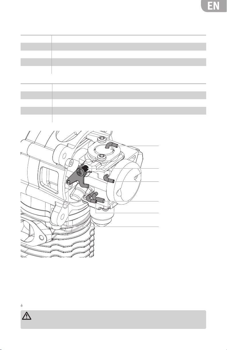
A. Prime Port
B. Idle Screw Adjustment
C. Fuel Feed (F)
D. Testing Port (T), Capped
E. Fuel Return (R)
F. Throttle Arm
Installing the Engine
Secure the engine to the airplane firewall using either M6 or 1/4–20 bolts. Use spacers or
standoffs as needed to set the correct firewall-propeller distance according to the airplane
manufacturer’s instructions.
Refer to end of the manual for a full-size firewall template cutout.
WARNING: Tighten all engine mounting screws before each flight. If you do not tighten
the engine mounting screws, the screws may vibrate loose and cause the engine to
separate from the fuselage.
5
Page 6
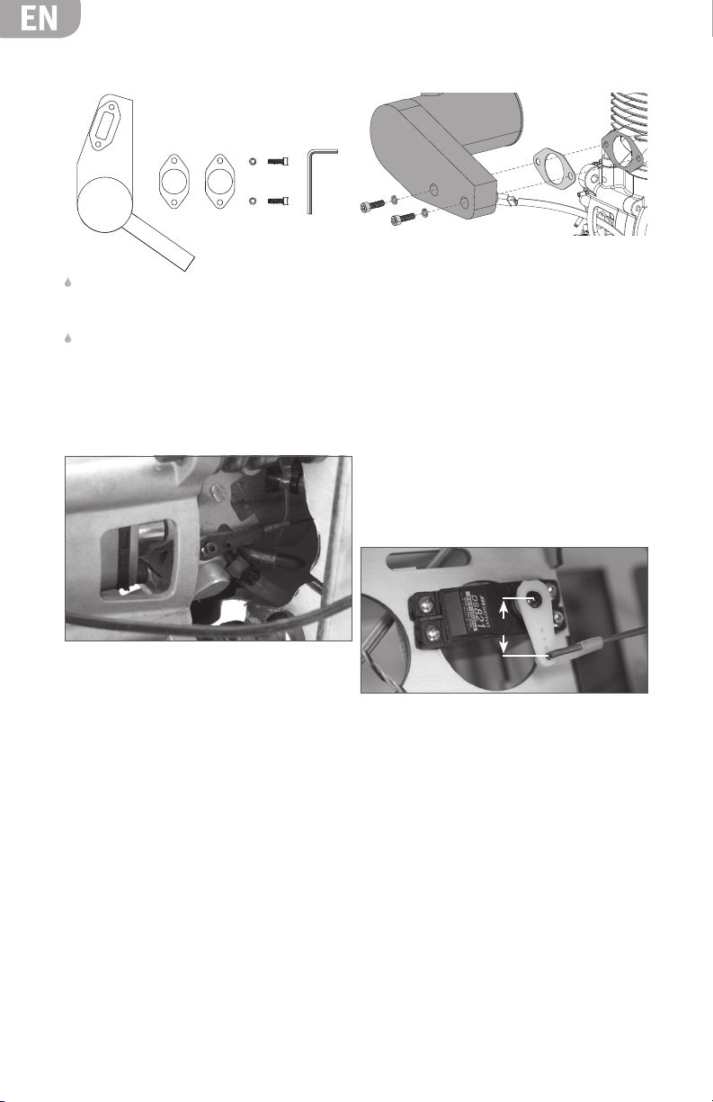
Installing the Muffler
The muffler mounting accessory package
includes mounting screws (2), lock washers
(2), muffler gaskets (2) and an L-wrench.
We suggest using high-temperature RTV as a
locking agent on the muffler screws to keep
them tight.
Connecting the Throttle Linkage
1. Put a lock washer on each of the muffler
screws. Push the muffler screws through the
muffler.
2. Place the muffler gasket over the muffler
mounting screws.
3. Align the muffler gasket with the exhaust
opening and the muffler mounting screws.
4. Tighten the muffler screws.
6. Move the linkage connected to the throttle
body to full-idle (forward). On the servo
arm, find the hole that is closest to 16mm
(5/8 in) from the center of the arm. Mark the
pushrod where it meets this hole.
1. Use a 3mm ball-link to attach the throttle
linkage to the throttle arm on the throttle
body.
2. Power ON the transmitter and receiver. Move
the throttle stick and throttle trim to center.
3. Place the servo arm on the throttle servo so
the arm is perpendicular (90°) to the throttle
linkage.
4. Ensure the throttle servo is moving in the
appropriate direction. The throttle servo arm
should move towards the engine when the
throttle stick is moved to low throttle. If it
doesn’t, reverse the servo direction in your
transmitter. If you use servo reversing, you
will need to rebind your transmitter to the
receiver for failsafe to function properly.
5. Move the throttle stick to low throttle on the
transmitter. Reduce the throttle trim to its
lowest setting.
16mm
7. Using pliers, bend the pushrod so there is a
90° bend at the mark.
8. Using a pushrod keeper, secure the pushrod
in the servo arm.
9. Check that the throttle arm on the throttle
body can travel fully open and fully closed
(both have hard stops). Adjust your
transmitter endpoints to ensure full travel.
10. If there is a large difference between the
endpoints, adjust the endpoints and subtrim to find a balance where the endpoints
are approximately within 10% of each
other.
6
Page 7
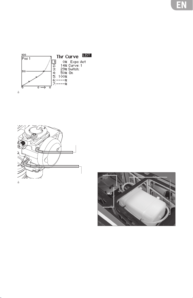
Throttle Curve Setup
The engine’s throttle body flapper valve provides
non-linear engine response to throttle changes
(greater power increase between low throttle to
50% than 50% to full throttle). We recommend
using the Throttle Curve feature on your
transmitter to provide a more linear response.
Using these Throttle Curve settings, shown
from a Spektrum™ DX18 transmitter screen
shot, with a properly setup throttle linkage will
provide a very linear feel to the throttle.
Attaching the Fuel Lines
Fuel Feed (F)
Fuel Return (R)
Refer to the Fuel Delivery System section for
information on plumbing the fuel tank. This
system uses a new setup and requires special
attention when setting up the fuel tank.
1. Connect the medium diameter Viton fuel
tubing to the fuel tank supply line and the
fuel tubing connector on the throttle body
labeled “F”.
2. Connect the medium diameter Viton fuel
tubing to the vent line. Run this fuel line
either around the back of the tank or make
a loop on top of the tank to create an “antisyphoning” loop. Take the other end of the
fuel line and route it outside the airplane
fuselage.
1. Ensure you have set up the throttle linkage
as described in the Connecting the Throttle
Linkage section. It is very important that the
low throttle and high throttle endpoint travel
of your servo be as close to even as possible
(i.e. Low throttle, trim closed -100%, high
throttle 100%). A variation of as much as
10% between these two values is tolerable.
2. Enter the numbers from the diagram into
your transmitter’s Throttle Curve menu and
activate exponential (if applicable).
3. Once the engine is started and running
correctly, check the feel of the throttle
response. Adjust it to your liking through
your transmitter’s programming screen.
3. Connect the medium diameter Viton fuel
tubing to the return port on the throttle body
labeled “R”. Connect the other end of this
line to a tee. Connect one end of the tee to
the fueling line in the tank and the other
end to the aircraft fuel inlet wherever you
feel is most appropriate. We recommend
you use an external fuel dot in order to fuel
the airplane without needing to remove any
hatches or cowls.
C
B
A. Tank Vent Tube
B. Fuel to EFI Unit
C. Return Line from EFI and Tank Fill Tube
A
7
Page 8

Attaching the Propeller and Spinner
3. Begin to tighten all 4 screws until they are all
hand-tight.
4. Tighten all screws with the included 4mm
L-wrench in a clockwise circle until all screws
are tight.
5. Install the spinner cone. Make sure the
spinner cone is not touching the propeller.
Trim the propeller opening if necessary.
6. Tighten the spinner screw to secure the
spinner cone.
Refer to the Propeller Drilling section for
instructions on how to properly drill a
propeller.
1. Remove the 4 propeller screws from the prop
driver.
2. Insert the 4 screws through the front prop
washer, followed by the propeller, spinner
backplate, rear prop washer and finally
thread them into the prop driver.
Recommended Propellers
22 x 10–24 x 10 (a Falcon 23 x 9 has tested
to be the best performer with this engine,
although the performance is very good
throughout the recommended range).
Propeller Drilling
Use a manufacturer’s drill guide to drill four holes in the propeller. The guide ensures that the
propeller bolts align with the driver and do not cross-thread. If you do not have a drill guide, use
one of the propeller washers from the engine; however, this method is not recommended and may
result in poor fitment and damage to the propeller washer. If using a propeller washer, follow the
same instructions as below. Using a drill press is also highly recommended, but not required.
1. If your propeller has a 10mm (0.39 in) center
hole, move to Step 2. If not, use a propeller
reamer to widen the center hole to 10mm.
2. Place the drill guide into the propeller center
hole.
3. Align the bolt pattern where it is convenient
when mounted on the engine. See below
for the best alignment. This will orient
the propeller so that it is in a comfortable
position to hand-start when up against
compression. It is best to check this on your
engine first.
60°
45°
4. While using a secure method to hold the
propeller and drill guide (we recommend
a vise), drill the first hole (order does not
matter). Drill carefully and take your time.
The more precisely you drill the propeller,
the better the fitment of the bolts. If drilling a
carbon fiber propeller, pull the bit out every
few seconds to clear the hole of any material
and allow the bit to cool. Drilling through
carbon fiber is tough on drill bits and takes
longer to complete than wood or plastic.
5. Before drilling any more holes, take a propeller
bolt and place it in the newly created hole. This
will help keep the drill guide aligned and keep
it from rotating when drilling the other holes.
6. Drill the rest of the holes.
7. Remove the drill guide.
8. If desired, take a chamfering tool and
carefully cut a chamfer in each hole on each
side of the propeller.
8
Page 9

Connecting the System Wiring Harness Assembly
The battery voltage required is 8.4V (2S Li-Po battery). Do not use a voltage regulator.
We recommend a 2S Li-Po battery (such as the Spektrum Li-Po Receiver Pack 2000mAh
(SPMB2000LP)) as we have done extensive testing with this pack. The maximum current draw at
full throttle is 650mA, and our more typical average has been between 300–350mA.
The assembly consists of:
• Ignition module with battery connector, ignition sensor connector, tachometer readout
connector and spark plug connector
• Ignition sensor (already attached to your engine)
• Sensor magnet (already installed in the prop drive hub of your engine)
• EFI (Electronic Fuel Injection) module, wiring harness with power and RPM pickup connectors
• Switch to power EFI and ignition module (not included)
• 2S Li-Po battery (not included)
Mounting Your Electronic Ignition
• You can mount the unit in any orientation
and place that is convenient for your
installation. You can also mount it to
the firewall or under the engine firewall
extension if your airplane is so equipped.
Keep in mind that it should be mounted
away from the heat of the muffler.
• Secure the ignition module to your chosen
location with foam padding to provide
vibration isolation. We typically mount it
conveniently with tie wraps after wrapping
the ignition in lightweight 1/4-inch foam
rubber. You can also use the mounting ears
on the ignition to secure it to your aircraft
using screws.
• You may need to route both the spark plug
connector wire and the ignition sensor wire
through the firewall, so be sure to plan
ahead and provide adequately sized holes
that will allow you to pull either the ignition
sensor connector or the spark plug cap
connector through the holes for later ignition
removal.
• Mount a good quality radio receiver type
switch (EVOA112) between the EFI/ignition
unit and the battery. Mount this switch in a
convenient place on the outer fuselage close
to the front of the airplane to make it easy
to turn the system on and off. Being able to
easily shut off the engine power supply is an
important safety consideration.
• The input side of this switch should be
connected to your battery used for the
engine power system. The output side of
this switch should connect directly to the EFI
wiring harness labeled “Power”.
• Connect the ignition sensor wire to the
ignition module. The sensor wire will only
fit into one of the connectors so you cannot
connect it wrong.
• Connect the ignition module tachometer
output to the EFI wiring harness connector
labeled “Tach in”.
• Connect the red power lead from the ignition
module into the wiring harness lead labeled
“Ign Power”.
• For added security and controllability, add
an additional radio-operated kill switch
(such as the Optical Ignition Kill Switch
EVOA100) between the engine system
battery and the input side of the ON/OFF
switch.
• If desired, you can connect either the
separately available tachometer readout or
the included Evolution/Spektrum Telemetry
Adapter Cable (EVOA107) to the connector
labeled “Telemetry” on the EFI wiring
harness. Plug the other end of the adapter
cable into the Spektrum telemetry module’s
rpm input port.
• Connect the spark plug connector to the
spark plug. This spark plug connector
utilizes a locking snap ring to ensure a solid
connection. Push it straight onto the spark
plug to secure.
• Make sure you charge your ignition battery.
You are now ready to operate your electronic
fuel injection equipped engine.
9
Page 10

Fuel
This engine requires a mix of 32:1 gas to oil
lubricant ratio for break-in and a mix of 40:1
gas/oil ratio for normal operation in order to
last a long time.
The needle bearing at the bottom end of the
conrod depends upon this lube ratio to operate
properly.
Do not go leaner than a 32:1 gas/oil ratio
for the first gallon of fuel. After this you may
decrease the oil content to a 40:1 gas/oil ratio
if desired. Do not go leaner than a 40:1 gas/
oil ratio or the warranty on your engine will be
voided.
Fuel Delivery System
It is very important to properly construct
your fuel supply system to avoid operating
problems. Our experience has shown that
many seemingly engine related operating
problems are in fact fuel delivery problems, not
engine related problems.
Fuel Filtering
Because of the incredibly small passages in the
injection system, even the smallest impurities
introduced into the fuel delivery system can
cause issues. For that reason, filtration of the
fuel is mandatory in a few different spots in the
system:
1. Between the fuel jug and the airplane fuel
tank.
2. Within the fuel tank itself (with the included
Sintered Plastic Filter Clunk (EVOA121)).
Tank Choice and Construction
Choose a tank with at least 24 oz (700mL)
capacity. A 24 oz tank will yield 12 minutes of
flying time. This engine has a fuel consumption
rate of about 2.2 oz/min (65 mL/min) at full
throttle.
• Ensure you use a tank stopper made for use
with gasoline and/or smoke oil.
• The EFI system requires a three-line tank
system; one for the line to the carburetor
fuel feed port with the sintered plastic filter
clunk attached internally, one for the vent
line from the tank to the outside of the
airplane, and one serving double duty to
fuel/defuel the tank, and act as a return
line from the throttle body. A “T” fitting (like
the one included with the Hangar 9
Filler with “T” Fitting and Overflow Fitting
®
Fuel
To properly mix the fuel, for a mix of 32:1 gas
to oil, add 4.0 oz of good quality 2-stroke oil to
one gallon (or 31 mL of oil to one liter) of 87–93
octane fuel. (EVOX1001Q Evolution 2-stroke oil
is recommended) We prefer to add the oil first
to our fuel container and to add the gasoline
second. This helps to ensure a good mixture of
the oil with the fuel at the outset.
We have tested our own Evolution 2-stroke oil,
Valvoline, Shell, RedLine and Husqvarna oils.
Other quality 2-stroke oils should work as well.
(HAN116)) is used to connect the fueling
tube to the return line.
Gasoline-resistant Rubber Cap
Fuel Tank
Vent Tube
To Outer Fuselage for Fueling
Fuel Return from
Throttle Body (R)
Fuel Inlet on
Throttle Body (F)
Sintered Clunk
• Ensure you use the provided Viton tubing in
all the plumbing of the tank, externally and
internally.
• Ensure you use the included sintered plastic
filter clunk inside the fuel tank.
• Ensure there is a good seal system for
the dedicated fueling/defueling line. We
highly recommend the HAN116 Fuel Filler
Assembly for its sleek look and ease of use
when installed on your airplane. This Fuel
Filler package also includes the “T” fitting
required for the tank system as outlined
above.
Gasoline-resistant Tube
10
Page 11

Engine Fuel Injection System in Operation
The 62 GXI features an adaptive algorithm that will “learn” the best settings for your
environment and flying conditions every time you run the engine. When the engine is shipped
from the factory, it is loaded with base settings that will enable you to run the engine in any
environment. As the engine runs, the adaptive algorithm fine-tunes the settings for your
environment. Every time you power off the EFI, it resets back to the default settings.
Engine Break-in
Your new engine needs to be broken-in to ensure a long life of all the components. This engine
features a piston ring design, which requires a specific break-in procedure to ensure a tight seal
between the piston ring and liner. For this to be accomplished, this process requires repeated
heating and cooling cycles. The ring needs to seat itself with the cylinder walls for it to develop
a good seal.
Important considerations during break-in
• Perform the break-in process with the engine
mounted on your airplane. There is no need
to bench-run the engine prior to mounting it
on your airplane.
• Use a lightly loaded break-in prop to begin
your break-in process (22 x 10 or 23 x 9).
This provides less load and high RPM that,
when matched with the heat of the engine,
will break in the engine properly. We do NOT
recommend using a 24 x 10 propeller during
the first gallon of fuel, as this propeller is
highly loaded and would put undue stress
on the engine during break-in.
• Use the proper recommended fuel with a
32:1 gas to oil ratio for the first gallon of
operation.
Break-in process
• First tank of fuel: Run the engine on the
ground for its first tank of fuel and DO NOT
go above half throttle. Cycle the throttle
between idle and half throttle every minute.
• Second tank of fuel: Do not run at full
throttle on the ground for more than 30
seconds at a time. Fly the airplane and avoid
extended periods of heating the engine. Be
sure to mix-in some cool-down dives and
lower-throttle flying.
• Third tank of fuel: Fly the engine at high
throttle setting for extended periods of time.
This will help the piston ring and cylinder to
expand and contract, helping the breakingin process.
• Fourth tank of fuel: Select one of the
recommended propellers for normal
operation and mount it on your engine.
Continue to break-in the engine in flight.
Fly the airplane through the first gallon of fuel,
then you can change the fuel mixture to 40:1
for continued operation.
11
Page 12

Telemetry
Telemetry is a huge asset to help you take
care of your engine. The EFI/ignition module is
even capable of communicating with Spektrum
telemetry systems directly so you won’t have
to add an additional RPM sensor. You will need
to connect the Evolution Ignition Telemetry
Adapter (EVOA107) between the “Telemetry”
connector on the EFI wiring harness and the
RPM port on your Spektrum telemetry module
in order to utilize this feature. Telemetry
systems other than Spektrum may require a
dedicated RPM sensor.
We recommend using the Spektrum DSMX Full
Range Aircraft Telemetry Module (SPM9548)
in conjunction with the included adapter. This
system allows you to see real-time RPM and
temperature readings from the engine.
Starting and Running the Engine
It is critical to the proper operation of your 62
GXI that you use the included filtered clunk.
Fuel should also be filtered in your fueling
system before it enters your model. Failure to
properly filter the fuel before it reaches your
engine will have a negative impact on the
engine’s performance and reliability.
1. Power ON the radio system but leave the
engine power system OFF.
2. On the first flight of the day, press the primer
bulb 10 times. There is no need to worry
about flooding the engine. If the primer bulb
is pressed too many times, it will only return
the extra fuel to the fuel tank.
3. Move the throttle trim to the center position
and keep the throttle stick at idle.
4. Power ON the engine power system.
The temperature sensor should be wrapped
around the base of the spark plug on the
cylinder head with the thermistor facing
towards the front of the engine. Using
telemetry gives you an accurate representation
of actual temperature and rpm figures during
use, and warnings can be set to go off if your
engine is getting too hot.
The temperature range should be 190–240°F
(87–115°C) on average. Set your maximum
temperature warning to go off if the engine
exceeds 270°F (132°C). If your engine is
continually near this peak temperature or
higher, immediately decrease throttle to bring
the temperature down.
If this continues to occur, land the airplane
and investigate getting more effective cooling
to the engine. Often this is accomplished
by adding baffling that directs the intake
air more directly over the engine. Or you
can increase the hot air exhaust area from
the cowl. It is not good for the engine to run
at temperatures this high and could cause
damage if not attended to.
5. Rotate the propeller counterclockwise until
it is against compression. Flip the propeller
through compression until it starts.
6. Let the engine run at high idle for 30
seconds to stabilize the temperatures.
7. Lower the throttle trim to your desired idle
setting.
If the engine doesn’t start quickly
1. Check to make sure fuel is moving through
the EFI by pressing the primer bulb and
watching the fuel lines.
2. If the engine appears not to have any fuel,
repeat the priming procedure in step 2.
Repeat 1–4 of Starting and Running the Engine.
12
Page 13

Troubleshooting Guide
If the Engine Does Not Start
• Check and use a new spark plug if needed.
Check by removing the spark plug from
the cylinder. Remove the spark plug and
resinstall it into the ignition plug cap. With
the engine power system ON, move the
sensor magnet past the sensor quickly (by
flipping prop or manually moving the sensor
past the magnet). You should be able to
either see or hear the clicking of the spark
plug firing. The engine RPM needs to exceed
180 RPM before the ignition system will fire
the spark plug. Make sure to rapidly move
the magnet past the sensor when checking
for proper operation.
• Check fuel lines for damage or kinks. If any
of the lines are restricted, the fuel system
will likely not operate. Clean and intact lines
are essential for the EFI system to operate
properly.
• Check for proper mechanical function by
turning the engine over.
• Check that the throttle body is correctly
installed and that all gaskets between
the EFI unit and engine are intact and
undamaged.
• With the engine power system ON, move the
ignition sensor past the magnet (as outlined
above) and listen for the EFI unit to click. If
you do not hear a clicking (the spark plug
not firing) coming from the EFI unit, charge
your engine power system battery.
• Check that the vent line is attached and free
from any bends or blockages.
If the engine runs erratic
• Check for fuel systems problems. Are there
any holes in the fuel lines (inluding the
clunk line inside the fuel tank) or other
possible sources of air leaks?
• Ensure the spark system is working properly
and the engine power system battery is
charged.
Mechanical Faults
If the engine cannot be turned over easily:
• The most likely cause is the engine is
flooded and by turning the engine over you
are trying to compress the fuel, not air.
1. Remove the spark plug.
2. Cover the cylinder head with a cloth or
paper towel and turn the propeller over
to expel all the excess fuel.
3. Replace the spark plug and try starting
again.
• A possible cause is the piston in the cylinder
is seized: loosen and unscrew the muffler
bolts. Visually inspect the piston and
cylinder through the exhaust port. If there
are excessive/deep scratches or grooves in
the piston, please contact Horizon Hobby
Customer Support for more information.
Repair of a seized piston/cylinder is
mechanical and should not be attempted.
Mechanical repairs must ALWAYS be completed
by an authorized Horizon Hobby service center.
Maintenance
After each flying session, fully drain the fuel
from the tank.
If you need additional help or have any
questions, please call Horizon’s Support
Team. Horizon has trained technicians who are
qualified to answer your engine questions.
13
Page 14

62 GXI Evolution Engines Specifications
78mm
88mm
38.5mm
66mm
47.4mm
Disp 62cc Weight
Bore 46.0mm Engine Only 53.8 oz
Stroke 37.0mm Muffler 8.2 oz
Cylinder Ringed Ignition 4.6 oz
Propeller 23 x 9 @ 7300 rpm Total 66.6 oz
Propeller Specifications
Propeller RPM Low RPM High
Xoar (wood) 22 x 10 6950 7200
Xoar (wood) 23 x 8 6900 7200
Mejzlik (CF) 23 x 8 6950 7100
Mejzlik (CF) 23 x 10 7000 7150
Mejzlik (CF) 24 x 10 6400 6600
Falcon (CF) 23 x 9 7250 7400
Falcon (CF) 23 x 10 6900 7200
41mm
129mm
176.4mm
44mm
75mm
126.4mm
88mm
147.9mm
ø30mm
Parts List
# Description Part
1 Carb Mounting Bolt Set EVOG620841
2 Throttle Body EFI EVOG62400
3 Carb Gasket (2) EVOG620842
4 Carb Mounting Block EVOG620840
5 Plastic Reed Cage EVOG620835
6 Reed Mount Strap (2) EVOG620836
7 Intake Reeds (2) EVOG620837
14
Page 15

# Description Part
8 Reed Cage Gasket Set EVOG620834
9 Crankcase Bolt Set EVOG620326
10 Exhaust Mount Bolts with Gasket M5 x 16 EVOG620328
11 Wraparound In-Cowl Muffler EVOM6
12 Exhaust Flange Gasket (2) EVOG620327
13 Spark Plug 33GX (CM6) EVOG33350
14 Cylinder Head EVOG620329
15 Cylinder Gasket EVOG620325
16 Piston Ring EVOG620424
17 Piston EVOG620423
18 Piston Pin with Clips EVOG620421
19 Rear Crankcase EVOG620531
20 Conrod Retaining Screw EVOG620219
21 Lower Conrod Bearing EVOG620218
22 Conrod Assembly EVOG620216
23 Crankshaft Stuffer Assembly EVOG620114
24 Crankshaft EVOG620112
25 Woodruff Key (2) EVOG620111
26 Rear (Main) Crankshaft Bearing EVOG620509
27 Crankcase Alignment Keys (2) EVOG620510
28 Front Crankcase with Bearings EVOG620507
29 Front Crankshaft Bearing EVOG620508
30 Ignition Pickup Magnet EVOG620706
31 Prop Driver with Key EVOG620705
32 Prop Drive Retaining Bolt EVOG620704
33 Rear Prop Washer EVOG620702
34 Front Prop Washer EVOG620701
35 Prop Bolt Set (4) M5 x 45 EVOG620703
36 Ignition Sensor and Mount Set EVOG620601
37 Engine Gasket Set 62GXI EVOG620850
Evolution/Spektrum™ Telemetry RPM Adapter Cable EVOA107
Medium Diameter Viton Tubing (1 meter) EVOA117
Sintered Plastic Filter Clunk EVOA121
15
Page 16

Exploded View
2
3, 37
1
1
5
4
8, 37
11
6
7
10
10, 12, 37
9
20 2119
22
13
9
14
15, 37
16
17
18
23
36
24
25
26, 28
2723 28
16
28, 29
30
31
32
33
34
35
Page 17

2-YEAR LIMITED WARRANTY
What this Warranty Covers - Horizon Hobby, LLC
(Horizon) warrants to the original purchaser that
the product purchased (the “Product”) will be
free from defects in materials and workmanship
for a period of 2 years from the date of purchase.
What is Not Covered - This warranty is not
transferable and does not cover (i) cosmetic
damage, (ii) damage due to acts of God, accident,
misuse, abuse, negligence, commercial use, or
due to improper use, installation, operation
or maintenance, (iii) modification of or to any
part of the Product, (iv) attempted service by
anyone other than a Horizon Hobby authorized
service center, (v) Product not purchased from
an authorized Horizon dealer, or (vi) Product not
compliant with applicable technical regulations.
OTHER THAN THE EXPRESS WARRANTY ABOVE,
HORIZON MAKES NO OTHER WARRANTY OR
REPRESENTATION, AND HEREBY DISCLAIMS ANY
AND ALL IMPLIED WARRANTIES, INCLUDING,
WITHOUT LIMITATION, THE IMPLIED WARRANTIES
OF NON-INFRINGEMENT, MERCHANTABILITY
AND FITNESS FOR A PARTICULAR PURPOSE. THE
PURCHASER ACKNOWLEDGES THAT THEY ALONE
HAVE DETERMINED THAT THE PRODUCT WILL
SUITABLY MEET THE REQUIREMENTS OF THE
PURCHASER’S INTENDED USE.
Purchaser’s Remedy - Horizon’s sole obligation
and purchaser’s sole and exclusive remedy
shall be that Horizon will, at its option, either (i)
service, or (ii) replace, any Product determined
by Horizon to be defective. Horizon reserves the
right to inspect any and all Product(s) involved
in a warranty claim. Service or replacement
decisions are at the sole discretion of Horizon.
Proof of purchase is required for all warranty
claims. SERVICE OR REPLACEMENT AS PROVIDED
UNDER THIS WARRANTY IS THE PURCHASER’S
SOLE AND EXCLUSIVE REMEDY.
Limitation of Liability - HORIZON SHALL NOT BE
LIABLE FOR SPECIAL, INDIRECT, INCIDENTAL OR
CONSEQUENTIAL DAMAGES, LOSS OF PROFITS
OR PRODUCTION OR COMMERCIAL LOSS IN
ANY WAY, REGARDLESS OF WHETHER SUCH
CLAIM IS BASED IN CONTRACT, WARRANTY,
TORT, NEGLIGENCE, STRICT LIABILITY OR ANY
OTHER THEORY OF LIABILITY, EVEN IF HORIZON
HAS BEEN ADVISED OF THE POSSIBILITY OF
SUCH DAMAGES. Further, in no event shall the
liability of Horizon exceed the individual price
of the Product on which liability is asserted. As
Horizon has no control over use, setup, final
assembly, modification or misuse, no liability
shall be assumed nor accepted for any resulting
damage or injury. By the act of use, setup or
assembly, the user accepts all resulting liability.
If you as the purchaser or user are not prepared
to accept the liability associated with the use
of the Product, purchaser is advised to return
the Product immediately in new and unused
condition to the place of purchase.
Law - These terms are governed by Illinois law
(without regard to conflict of law principals).
This warranty gives you specific legal rights,
and you may also have other rights which vary
from state to state. Horizon reserves the right
to change or modify this warranty at any time
without notice.
WARRANTY SERVICES
Questions, Assistance, and Services - Your local
hobby store and/or place of purchase cannot
provide warranty support or service. Once
assembly, setup or use of the Product has been
started, you must contact your local distributor
or Horizon directly. This will enable Horizon to
better answer your questions and service you
in the event that you may need any assistance.
For questions or assistance, please visit our
website at www.horizonhobby.com, submit
a Product Support Inquiry, or call the toll free
telephone number referenced in the Warranty
and Service Contact Information section to
speak with a Product Support representative.
Inspection or Services - If this Product needs
to be inspected or serviced and is compliant
in the country you live and use the Product in,
please use the Horizon Online Service Request
submission process found on our website or
call Horizon to obtain a Return Merchandise
Authorization (RMA) number. Pack the Product
securely using a shipping carton. Please note
that original boxes may be included, but are not
designed to withstand the rigors of shipping
without additional protection. Ship via a carrier
that provides tracking and insurance for lost or
damaged parcels, as Horizon is not responsible
for merchandise until it arrives and is accepted
at our facility. An Online Service Request is
available at http://www.horizonhobby.com/
content/_service-center_render-servicecenter. If you do not have internet access,
please contact Horizon Product Support to
obtain a RMA number along with instructions
for submitting your product for service. When
calling Horizon, you will be asked to provide
your complete name, street address, email
address and phone number where you can be
reached during business hours. When sending
product into Horizon, please include your RMA
number, a list of the included items, and a brief
summary of the problem. A copy of your original
sales receipt must be included for warranty
consideration. Be sure your name, address, and
RMA number are clearly written on the outside
of the shipping carton.
17
Page 18

NOTICE: Do not ship LiPo batteries to Horizon.
If you have any issue with a LiPo battery,
please contact the appropriate Horizon Product
Support office.
Warranty Requirements - For Warranty
consideration, you must include your original
sales receipt verifying the proof-of-purchase
date. Provided warranty conditions have been
met, your Product will be serviced or replaced
free of charge. Service or replacement decisions
are at the sole discretion of Horizon.
Non-Warranty Service - Should your service
not be covered by warranty, service will be
completed and payment will be required
without notification or estimate of the expense
unless the expense exceeds 50% of the retail
purchase cost. By submitting the item for
service you are agreeing to payment of the
service without notification. Service estimates
are available upon request. You must include
service. Non-warranty service estimates will
be billed a minimum of ½ hour of labor. In
addition you will be billed for return freight.
Horizon accepts money orders and cashier’s
checks, as well as Visa, MasterCard, American
Express, and Discover cards. By submitting any
item to Horizon for service, you are agreeing
to Horizon’s Terms and Conditions found on
our website http://www.horizonhobby.com/
content/_service-center_render-service-center.
ATTENTION: Horizon service is limited to
Product compliant in the country of use and
ownership. If received, a non-compliant Product
will not be serviced. Further, the sender will be
responsible for arranging return shipment of
the un-serviced Product, through a carrier of the
sender’s choice and at the sender’s expense.
Horizon will hold non-compliant Product for a
period of 60 days from notification, after which
it will be discarded.
this request with your item submitted for
Warranty and Service Contact Information
Country of
Purchase
United States of
America
United Kingdom
Germany
France
China
Horizon Hobby Contact Information Address
Horizon Service
Center
(Repairs and Repair
Requests)
Horizon Product
Support
(Product Technical
Assistance)
Sales
Service/Parts/
servicecenter.horizonhobby.
com/RequestForm/
www.quickbase.com/db/
bghj7ey8c?a=GenNewRecord
888-959-2305
sales@horizonhobby.com
888-959-2305
sales@horizonhobby.co.uk
Sales: Horizon
Hobby Limited
+44 (0) 1279 641 097
Horizon
Technischer
service@horizonhobby.de
Service
Sales: Horizon
Hobby GmbH
Service/Parts/
+49 (0) 4121 2655 100
infofrance@horizonhobby.com
Sales: Horizon
Hobby SAS
Service/Parts/
+33 (0) 1 60 18 34 90
info@horizonhobby.com.cn
Sales: Horizon
Hobby – China
+86 (021) 5180 9868
4105 Fieldstone Rd
Champaign, Illinois,
61822 USA
Units 1–4 , Ployters Rd
Staple Tye, Harlow,
Essex, CM18 7NS, United
Kingdom
Christian-Junge-Straße 1
25337 Elmshorn,
Germany
11 Rue Georges Charpak
77127 Lieusaint, France
Room 506, No. 97
Changshou Rd.
Shanghai, China
200060
18
Page 19

Compliance Information for the European Union
Declaration of Conformity (in accordance with ISO/IEC 17050-1)
No. HH2014053006
Product(s): EVO Engines 62GXI w/SureFire.31
Item Number(s): EVOE62GXI
The object of declaration described above is in conformity with the requirements
of the specifications listed below, following the provisions of the European
EMC Directive 2004/108/EC:
EN55022:2010 + AC:2011
EN55024:2010
Signed for and on behalf of:
Horizon Hobby, LLC
Champaign, IL USA
May 30, 2014
Instructions for disposal of WEEE by users in the European Union
This product must not be disposed of with other waste. Instead, it is the user’s
responsibility to dispose of their waste equipment by handing it over to a designated
collections point for the recycling of waste electrical and electronic equipment. The separate
collection and recycling of your waste equipment at the time of disposal will help to conserve
natural resources and ensure that it is recycled in a manner that protects human health and
the environment. For more information about where you can drop off your waste equipment for
recycling, please contact your local city office, your household waste disposal service or where
you purchased the product.
Robert Peak
Chief Financial Officer, Horizon Hobby, LLC
19
Page 20

Full-size Firewall Template Cutout
Maßstabgetreue Darstellung des Motorspantausschnitts
Gabarit échelle 1 d’installation du moteur
Sagoma in dimensioni reali dell'ordinata motore
66mm
33mm
78mm
39mm
Engine Centerline | Mittellinie Motor
Lignes centrales du moteur | Linea centrale del motore
73
Page 21

2014 Horizon Hobby, LLC. Evolution, the Evolution logo, DSMX and the Horizon Hobby logo are registered trademarks of
©
Horizon Hobby, LLC.
The Spektrum trademark is used with permission of Bachmann Industries, Inc.
Team Orion is a registered trademark of Team Orion Europe S.A. Corporation. Tygon
Performance Plastics Corporation.
®
is a registered trademark of Saint-Gobain
All other trademarks, service marks and logos are property of their respective owners.
33575.1 Revised 05/2014
 Loading...