

Page 1

© 2005 Manufactured exclusively for Horizon Hobby, Inc.
www.horizonhobby.com
800-535-5551
7795
™
Page 2
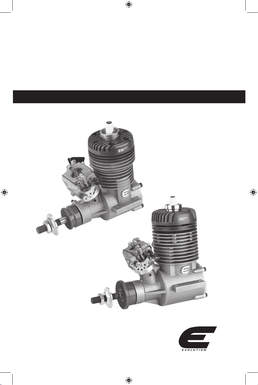
Evolution Engines
26GT/35GT
US ER G UI DE
™
Page 3

Introduction
Congratulations on your purchase of the newest and one of the most technically advanced 2-stroke gas model airplane
engines in the world. Whether you are new to the sport of model aviation or an experienced flyer, you will enjoy the
features of the new Evolution GT engine.
Evolution engines are designed to be the most powerful in their class, extremely easy to start and operate, and provide
years of enjoyable service. These engines incorporate many unique design features. Each feature is designed to
ensure success with your new engine.
This user’s guide is intended to provide the basic information required to operate and maintain your Evolution GT engine.
Important:
While the Evolution engine is extremely easy to operate, if this is your first experience flying a model airplane,
it is highly recommended that you have the help of an experienced modeler during the first few flights.
Your local hobby shop or flying club can put you in touch with an experienced pilot in your area.
2
Before using this engine, please read these instructions carefully.
Evolution Engines™ 2-Year Warranty
This Evolution Engines product is
guaranteed to be free from defects in
materials and workmanship for a period of
2 years from the date of purchase. During
this time, Evolution’s authorized service
center will repair or replace, at their option,
any defective parts without charge.
This warranty does not apply to damage
or defects resulting from misuse, neglect
or abuse; damage caused by customer
disassembly, use of substandard fuel,
use of incorrect accessories (spark plug,
propeller, etc.); or damage resulting from a
crash or any use of this engine other than
for which it is specifically intended. Any
of the above will automatically void the
warranty of the engine.
Should your engine require warranty or nonwarranty repair service, please package
it carefully and return it to the address at
the right, along with a copy of the original
invoice or receipt and a detailed letter
explaining the problems. Write your name,
address and daytime phone number clearly
on the letter and return it via FedEx, UPS
or insured Parcel Post (Evolution Engines
will not be responsible for product lost en
route).
For repairs not covered under warranty,
please specify in your letter whether you
want an estimate of the repair charges prior
to performing the service (which may cause
a slight delay). Payment for non-warranty
repairs should be made by credit card or
money order. Unless otherwise specified, all
repaired engines will be returned. We will
do everything we can to expedite the service
required to your Evolution product.
_________________________________
Evolution/Horizon Service Center
4105 Fieldstone Road, Champaign, IL 61822
1-217-355-9511
www.horizonhobby.com
Page 4

3
Mounting the Engine
Most model airplane designs make provision for an
engine mount. It is extremely important that the engine
mount be securely mounted to the airplane’s firewall
and that the engine is securely mounted to the engine
mount. Follow the instructions included with the
airplane for mounting the engine.
The engine should be fastened in place with 4 screws
through a conventional beam mount. Use 8x32 screws
(26GT) or 10x32 (35GT). If you decided to fasten the
engine using a flexible motor mount, always choose
parts with enough integrity and strength. Make sure all
screws are tightened and regularly check that they are
tight and in good condition.
Important: Air is necessary to cool the engine during
operation. Make sure that sufficient air circulation
through the cowling is provided. As a basic reference
the outlet area should be 3–5 times the area of the
inlet area to provide adequate cooling.
Throttle Linkage
Carefully attach the throttle linkage to the engine using
a ball link on the carburetor. Make sure that the linkage
is free to operate from low throttle to high throttle and
confirm that the low throttle setting on the transmitter
closes the carburetor butterfly to the low idle position.
Adjust the length of the pushrod until full throttle opens
the carburetor butterfly fully, while low throttle, low trim
completely closes the butterfly.
Attaching the Fuel Lines
Use medium gasoline-compatible fuel line in the
fuel tank as well as the supply line to the engine.
Selecting a Suitable Propeller
The Evolution 26GT and 35GT have been designed to
generate maximum power at 8500 rpm, according to the
type of exhaust used. If you wish to utilize the maximum
power output, choose a propeller, which will allow the
engine to reach these revolutions, or slightly lower
revolutions. (The engine will unload in the air depending
on the aircraft speed and propeller selected.) We do not
recommend using propellers that allow the engine to
reach more than 9000 rpm on the ground.
Suggested Propeller Dimensions
Evolution 26GT
16x8, 16x10, 16x11, 16x12,
17x8, 17x10, 17x12, 18x8
Evolution 35GT
18x8, 18x10, 20x8, 20x10,
20x12, 21x8, 21x10
Fuel for the Evolution Gas Engine
The Evolution gas engine has been designed to run
on a mixture of high quality unleaded gasoline and
synthetic oil intended for racing 2-stroke gasoline
engines. For the break-in period of the new engine,
mix the fuel in a ratio of 30 parts gasoline to 1 part
lubricant. After break-in use a ratio of 40 parts
gasoline to 1 part lubricant.
Page 5

4
1) Before attempting to start your engine make sure that the ignition is switched off, the choke valve is
closed and the throttle valve is about half opened. Then turn the engine 3–4 revolutions, assuming
the engine has not been flooded.
2) When you are ready to start the engine switch the ignition on, open the choke valve and set the throttle at a
slightly high idle speed. Be sure to have a helper hold the model securely. Using an electric starter begin cranking
the engine. It should fire within seconds of applying the starter. Allow the engine to idle for 30–45 seconds.
3) If the engine does not start even after using the starter to crank the engine a second time, open the
throttle to maximum, turn off the ignition and turn the engine about 4 revolutions. Switch the ignition on
again, then restart the engine with throttle at a fast idle position and the choke valve set open.
4) At this point if the engine still will not start, unscrew the spark plug and check its contacts. Clean any
possible excess fuel (i.e. an indication of engine flooding) and screw it in again. Further starting should only
be done with the throttle at idle position. If the plug is dry then probably not enough fuel has been drawn into
the carburetor. If that is the case, check the fuel feed and then return to the instructions given in paragraph 1.
After starting and warming the engine for 30–45 seconds adjust as follows:
Step I- Move the throttle to 2/3 high throttle position quickly (fast acceleration). Then repeat three times
— if the engine accelerates smoothly go to Step III. If acceleration is not smooth go on to Step II.
Step II- Faulty acceleration and a tendency to quit is usually attributable to a poor fuel mixture in the
medium rpm range. Stop the engine and recheck the fuel feed (the fuel line must not be pinched or broken).
Restart the engine and test acceleration again. If the problem persists adjust the carburetor. Open the low
speed needle by 5 minutes and retest. If acceleration is smooth, open the needle by another 3–5 minutes
— this should be done because the needle was previously set too lean; if atmospheric conditions changed
recently you may have to re-adjust the needle.
If the engine continues to not accelerate properly open the low speed needle by 10 minutes. If the engine’s
operation does not improve, shut it off and check the basic setting, restart the engine and test the
acceleration. If the engine runs correctly go to Step III. If it continues to not accelerate properly, open the low
speed needle by another 10 minutes. If acceleration is faulty, the defect is likely to lie somewhere other than an
adjustment.
Starting the Engine
Evolution Engines™ new carburetor comes
adjusted to a basic setting. This setting should be
maintained during the initial break-in runs.
Before you first start the engine, make sure
that the spark plug is screwed in and tightened
and that the plug socket is fitted in place and
fastened down properly. Fix the ignition sensor
in the proper position above the magnet with the
screws enclosed.
Important: Never turn the engine over with the
ignition turned on unless the spark plug is inserted
in the plug socket. This could lead to ignition
damage.
Carburetor Adjustments 26GT
Adjust needle (L) for low rpm range 1 turn and 50 minutes
Adjust needle (H) for high rpm 1 turn and 35 minutes
Basic setting: (minutes refer to the hands of a clock)
Carburetor Adjustments 35GT
Adjust needle (L) for low rpm range 1 turn and 45 minutes
Adjust needle (H) for high rpm 1 turn and 45 minutes
Air Pressure Inlet
Adjusting Needle L
Adjusting Needle H
Choke Lever
Pressure Inlet
Page 6

Step III- If the engine accelerates correctly, according to the above test, set it at idle speed and accelerate
to full speed. Repeat twice more. If the engine functions correctly, go to Step IV. If it cuts out, open the low
speed needle by 5–10 minutes more.
If the engine does not respond to acceleration fast enough, keep closing the low speed needle until the engine
starts to cut out in response to throttle opening. At that point reopen the low speed needle by 5–10 minutes.
Step IV- If the engine reacts correctly set it at full speed. If revolutions do not drop, the engine has been
adjusted successfully. If revolutions seem to drop, open the high speed needle by about 5–10 minutes.
Caution!
The engine must be stopped while you adjust the carburetor in order to prevent injury by the propeller.
Starting and running a new engine:
Having started the engine, leave it running for about 5 minutes at a higher idle speed. Then run it for about 20
minutes, while changing revolutions from idle to 1/2–3/4 of the range and shortly holding each position—gradually
prolong the holding periods. After 10 minutes of operation open the throttle to maximum for a period of about one
minute. At this point stop the engine and let it cool down. Then restart it and check the adjustment. If everything
is all right, you can make your first flight. During first few flights do not overload the engine and do not let it run at
high revolutions for long periods of time (very important during hot weather). Use up all the fuel that was mixed with
the oil that is included with your engine. From then on, fuel and oil should be mixed in the proportion 40:1
5
Trouble-Shooting Guide
If the engine does not start
-
check and use a new spark plug if needed. (Check
the spark: put the plug into the cable end and by
turning the engine you´ll see the necessary spark.
Note: The plug must touch a metal part of the engine.)
- check fuel lines.
- check for proper mechanical function by turning
the engine over.
- check that the carburetor is correctly installed.
- remove the carburetor cover from the feed side;
check the filter and blow off carburetor with
compressed air (Caution:
When using compressed
air, use eye protection.); when re-assembling be
careful to maintain the proper order of the components.
- check the vacuum feed line.
Mechanical Faults
If the engine can not be turned over easily
- a likely cause is the piston in the cylinder is seized:
loosen and unscrew the cylinder bolts.
- carefully remove the cylinder.
- visually examine the piston and crankcase to find
the likely cause of the engine’s mechanical problem.
Note: Mechanical repairs must always be completed
by a professional service department.
Page 7

6
26GT/35GT Evolution Engine Specifications
Bore
Stroke
Displacement
Weight of complete engine
without ignition*
Weight of ignition unit
RPM range
33mm
30.1mm
25.7cc/1.6 ci
936 g/2.06 lb
165 g/5.8 oz
1400–9500 rpm
Maximum power output**
Maximum torque**
Fuel
Lubrication
3.8 HP/9000 rpm
2.18ft-lb/8000 rpm
Unleaded gasoline
Oil w/gasoline
in mixture 1:40
* The value in the table above stands for the weight of a completely assembled engine, including the spark plug, carburetor,
drive washer and prop screws.
** Power output varies with the exhaust used. The value given in the table stands for the maximum available power output.
Evolution 26GT
Bore
Stroke
Displacement
Weight of complete engine
without ignition*
Weight of ignition unit
RPM range
35.5mm
35.2mm
34.80cc/2.15 ci
1493 g/3.3 lb
165 g/5.8 oz
1400–9000 rpm
Maximum power output**
Maximum torque**
Fuel
Lubrication
4.1 HP/8500 rpm
2.49ft-lb/7500 rpm
Unleaded gasoline
Oil w/gasoline
in mixture 1:40
Evolution 35GT
Page 8

GT Evolution Engine Dimensions
26 GT
35 GT
26 GT
35 GT
A
mm
146
182
F
mm
31
41
B
mm
99
118
G
mm
4.3
5.3
C
mm
50
60
H
mm
M10x1
M10x1
D
mm
70
84
I
mm
10
10
E
mm
60
70
J
mm
33
45
7
Page 9

8
Evolution Engines Ignition System
The spark ignition included with your Evolution Gas engine is a modern generation electronic ignition.
It will provide excellent operation for a long time if used correctly. Here are some features that you should
be aware of.
1. Automatic processor controlled timing advance that makes starting the engine easy.
2. During normal operation the battery voltage will decrease. When the voltage reaches 4.4V, you
will begin to notice a reduction in engine rpm. This is an indication that you should land your model
as soon as practical
3. The electronic ignition system on the Evolution 26GT and the Evolution 35GT is designed to operate
on 4.8 volts. The ignition system is not designed to use a 6-volt battery source.
4. The electronic ignition incorporates an rpm read-back function that enables the user to see the
maximum rpm that the engine achieved in the just completed flight. This is easily accomplished
by using your optical tachometer to read the frequency that the ignition system LED is flashing
after landing. This can be useful when selecting correct size propellers to match the in-flight rpm
to the engine’s horsepower and torque curves. You will have to multiply the observed rpm on the
tachometer by the number of propeller blades that you are using.
The electronic ignition unit requires a 4.8-volt battery source separate from your model’s radio system.
A 600mAH battery will provide more than 1.5 hours of operation. The supplied battery connector is
compatible with the JR radio battery connector.
While installing the ignition unit in your model, be careful to have all parts that are connected to the unit
and the engine situated as far as practical from the radio receiver and radio antenna. The throttle servo
should be mounted a distance of 8–12 inches from the engine. The spark plug cable must not touch any
part of the model structure as vibration may damage the cable. If this is not practical, it will be necessary
to provide an insulation material for the cable. The ignition unit itself should be wrapped in foam rubber
to prevent engine vibration from damaging the electronics. All components must be protected from contact
with engine fuel.
Before flying your model you must perform an interference check. Turn the ignition switch off, receiver on,
transmitter on and with the transmitter antenna collapsed. Walk with the transmitter to the limit of the
operating range (antenna collapsed). Have a helper turn on the ignition switch, start the engine and then
check for a reduction in range with the engine running. There should be no interference. If there are any
glitches from your radio system, do not fly until the interference is resolved.
Installation of the Ignition Unit
Page 10

9
Plug
Plug
Cap
Probe
BASIC PROBE AND MAGNE T ADJUSTMENT
Magnet
A
Magnet
B
Magnet
A
Magnet
B
Probe
Propeller Driver
Direction
of Rotation
Propeller Driver
Distance of probe from magnet 0:5 mm
Screw securing the connector in required position
Red
Brown
Orange
+
Data Out
Battery
Connector
To Battery
Switch
Magnet A position on the driver
corresponds to the
TOP DEAD CENTER of the piston.
Magnet B is oriented reversely.
Basic pre-ignition adjustment
is given by magnet A.
Magnet distance is 180 degrees.
Ignition
Module
Technical data
Battery Supply 4.8 Volts 600–1500mAh
Current Consumption 90–120mAh at Idle
500mAh/9000 rpm
Plug Voltage 18Kv
Weight 160 g
Dimension 55x50x25mm
Sensor Magnet Space max. 0.5mm (.020”)
Plug Spark Gap .7mm (.028”)
Working Temperature -10 to 85 deg C
Installation of the Ignition UnitInstallation of the Ignition Unit Continued
Page 11

10
Part Number Description Part Number Description
26GT
EVO30940101 Crankcase EVO30940951 Connecting Rod
EVO30940202 Front Bearing EVO30941001 Crankshaft
EVO30940203 Rear Bearing EVO30941101 Drive Washer
EVO30940301 Rear Cover EVO30941102 Drive Washer’s Taper Key
EVO30940302 Rear Cover Screws - Set EVO30941103 Propeller Nut
EVO30940303 Rear Cover “O”- Ring EVO30941104 Propeller Washer
EVO30940304 Pressure Nipple EVO30941106 Washer
EVO30940305 Pressure Fitting Gasket (2pcs) EVO30941305 Carburetor Gasket (2pcs)
EVO30940404 Carburetor Screw (2pcs) EVO30941306 Washer (2pcs)
EVO30940501 Cylinder Head EVO30941307 Carburetor Bolt
EVO30940502 Cylinder Head Screws (6pcs) EVO30941308 Carburetor Nut (2pcs)
EVO30940503 Cylinder Head Gasket (3pcs) EVO30941310 Thermo-Isolation Washer
EVO30940601 Cylinder Liner EVO30941321 Carburetor Flange
EVO30940650 Cylinder-Piston Assembly EVO30941403 Spark Plug Washer
EVO30940701 Piston EVO30941404 Locking Screw
EVO30940702 Piston Ring EVO30943224 Carburetor
EVO30940801 Piston Pin EVO30943306 Spark Plug
EVO30940802 Piston Pin Retainer
Page 12

11
Part Number Description Part Number Description
35GT
EVO30980101 Crankcase EVO30980951 Connecting Rod
EVO30980202 Front Bearing EVO30981001 Crankshaft
EVO30980203 Rear Bearing EVO30981101 Drive Washer
EVO30980301 Rear Cover EVO30941102 Drive Washer’s Taper Key
EVO30980302 Rear Cover Screws - Set EVO30941103 Propeller Nut
EVO30980303 Rear Cover “O”- Ring EVO30941104 Propeller Washer
EVO30940304 Pressure Nipple EVO30941106 Washer
EVO30940305 Pressure Fitting Gasket (2pcs) EVO30941305 Carburetor Gasket (2pcs)
EVO30940404 Carburetor Screw (2pcs) EVO30941306 Washer (2pcs)
EVO30980501 Cylinder Head EVO30941307 Carburetor Bolt
EVO30980502 Cylinder Head Screws (6pcs) EVO30941308 Carburetor Nut (2pcs)
EVO30980503 Cylinder Head Gasket (3pcs) EVO30941310 Thermo-Isolation Washer
EVO30980601 Cylinder Liner EVO30941321 Carburetor Flange
EVO30980650 Cylinder-Piston Assembly EVO30941403 Spark Plug Washer
EVO30980701 Piston EVO30941404 Locking Screw
EVO30980702 Piston Ring EVO30983224 Carburetor
EVO30980801 Piston Pin EVO30983306 Spark Plug
EVO30980802 Piston Pin Retainer
 Loading...